Characteristics Analysis and Measurement of Inverter-Fed Induction Motors for Stator and Rotor Fault Detection


1
School of Electrical Engineering, Beijing Jiaotong University, Beijing 100044, China
2
Department of Energy Technology, Aalborg University, 9220 Aalborg, Denmark
3
Beijing Engineering Research Center for Electrical Rail Transit, Beijing 100044, China
*
Author to whom correspondence should be addressed.
Energies 2020, 13(1), 101; https://doi.org/10.3390/en13010101
Submission received: 25 November 2019
/
Revised: 20 December 2019
/
Accepted: 20 December 2019
/
Published: 24 December 2019
(This article belongs to the Special Issue Advances in Rotating Electric Machines)
Abstract
:Inverter-fed induction motors (IMs) contain a serious of current harmonics, which become severer under stator and rotor faults. The resultant fault components in the currents affect the monitoring of the motor status. With this background, the fault components in the electromagnetic torque under stator faults considering harmonics are derived in this paper, and the fault components in current harmonics under rotor faults are analyzed. More importantly, the monitoring based on the fault characteristics (both in the torque and current) is proposed to provide reliable stator and rotor fault diagnosis. Specifically, the fault components induced by stator faults in the electromagnetic torque are discussed in this paper, and then, fault components are characterized in the torque spectrum to identify stator faults. To achieve so, a full-order flux observer is adopted to calculate the torque. On the other hand, under rotor faults, the sidebands caused by time and space harmonics in the current are analyzed and exploited to recognize rotor faults, being the motor current signature analysis (MCSA). Experimental tests are performed on an inverter-fed 2.2 kW/380 V/50 Hz IM, which verifies the analysis and the effectiveness of the proposed fault diagnosis methods of inverter-fed IMs.
1. Introduction
In recent years, researches on the condition monitoring and health prognosis of electrical equipment are drawing more and more concerns. The reliabilities of converters and machines are directly related to the system, even human life, in applications such as photovoltaic (PV), electrical vehicle, etc. Fault-detection and tolerant operation of modular multilevel converters (MMC) are investigated in [1,2], where the latter deals with the insulated gate bipolar transistor (IGBT) open circuit fault. Fault diagnosis techniques related to machines are more diverse, where synchronous generators (SG) [3], permanent magnet (PM) machines [4,5,6], multi-phase machines [5,7,8], and induction motors (IM) [9,10,11] are involved, and winding short circuit fault [4,5], rotor broken bar fault [12,13], and eccentric and bearing faults [13] are discussed.
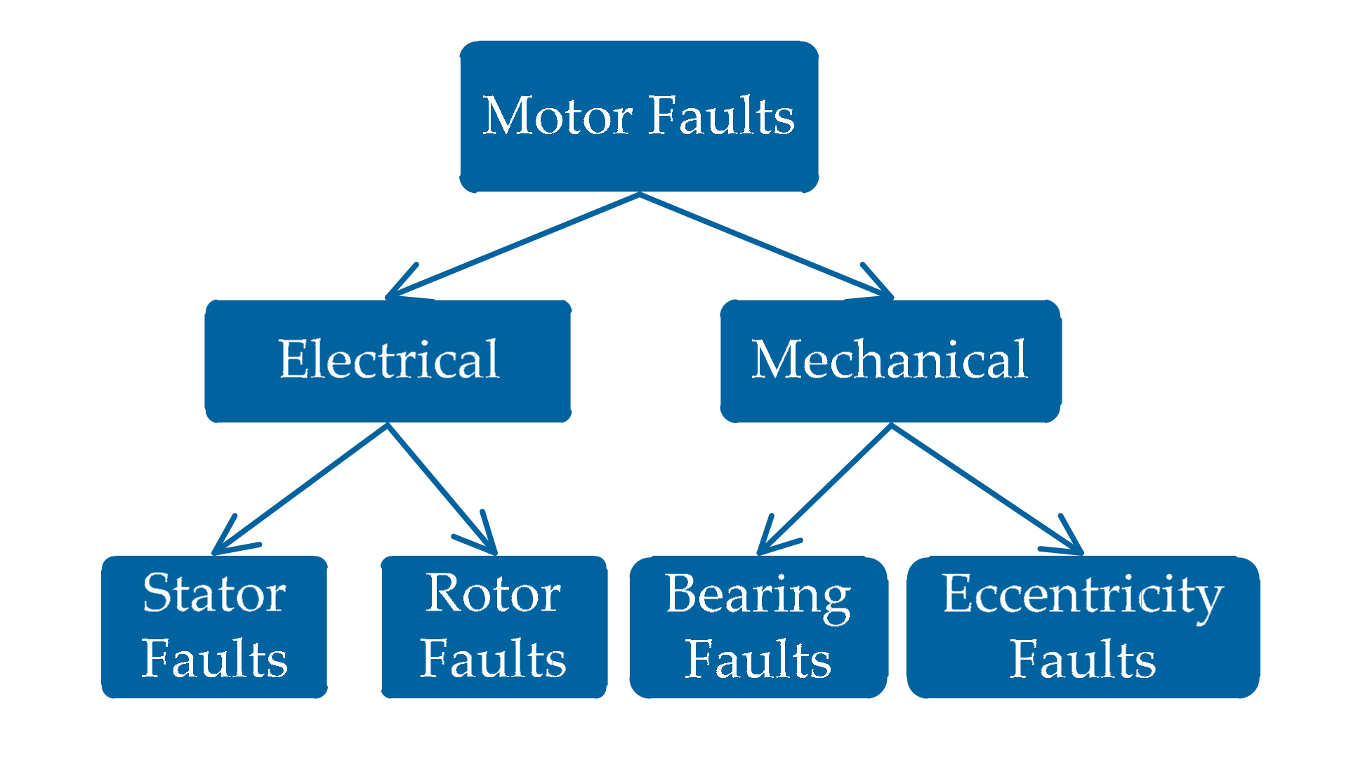
Induction motors (IMs) are widely applied in industry [11] and usually in harsh environments. This causes early motor faults, which may grow to irreparable failures if not properly treated. Motor faults can mainly be divided into two categories: Mechanical and electrical faults, as shown in Figure 1, where mechanical faults include bearing and eccentricity faults, and electrical faults include stator and rotor faults. According to [12], stator and rotor faults account for 37% and 10%, respectively, in all motor failures. Thus, many fault diagnosis techniques are presented. These fault diagnosis methods are divided into: Signal-based techniques, artificial intelligence (AI)-based techniques, and model-based techniques.
The fault diagnosis methods based on signal processing [13,14] are very popular in industry. A novel Park’s vector approach is investigated in [15,16], and the extended Park’s [17] and 3-D-ellipse [18] methods are then developed for stator fault diagnosis. The winding asymmetry of stator faults causes un-balanced three-phase currents. Thus, the methods based on negative current and impedance are applied to stator monitoring [19]. Many signal spectrum analysis techniques [16,20,21,22] based on time domain, frequency domain, and time–frequency domain of motor current signature analysis (MCSA) are proposed to analyze the (1 − 2s)f1 characterization for rotor fault detection, where s is the slip and f1 represents the base frequency. The fast Fourier transform (FFT) is used for the MCSA. However, the fault frequency (1 − 2s)f1 is easily covered by the fundamental frequency in the current spectrum, as s is usually small for inverter-fed IMs, where the rotor speed is very close to the stator frequency; thus, the time-windowing methods are proposed to weaken the influence of the spectrum leakage, and methods by removing the base frequency are considered. Furthermore, the high-resolution spectrum techniques such as the estimation of signal parameters via rotational invariance techniques (ESPRITs) [23,24], multiple signal classification (MUSIC) [25,26], root-MUSIC [25], and zoom-MUSIC (ZMUSIC) [26] are investigated in rotor faults detection. Finally, the time–frequency analysis methods of short time Fourier transform (STFT) [27,28], wavelet [29,30,31], and Wigner–Ville transform [32] are also applied to the MCSA.
The AI-based methods are investigated in the fault diagnosis. The diagnosis procedure usually includes the process of the signature extraction, signal processing, fault classification, and fault decision. For each fault, the signatures can be current, voltage, power, magnetic flux, torque, and vibration. The fault classification technique is crucial for the AI-based fault diagnosis. There are many artificial techniques that are applied to faults classification. Among them, the neural network (NN) is very popular. In [33], an early stator fault was detected through the NN. In [34], a cascaded NN was developed to classify faults. In [35], an artificial neural network (ANN) is used to train and classify different faults. In addition, [36] uses a hybrid fuzzy min-max NN and classification and regression tree (FMM-CART) to undertake data classification and rule extraction problems. Furthermore, the fault diagnosis method based on the support vector machine (SVM) is employed in [37,38] for motor faults. Moreover, classifiers based on C4.5, K-nearest neighbors (k-NNs), and multilayer perceptron (MLP) are discussed in [39,40] to recognize faults.
Model-based or parameter-based fault diagnosis methods utilize the deviation of critical parameters under fault conditions. For example, in [41], stator and rotor faults were modeled firstly, and then, the fault severity is estimated, and position is located by considering the prior information. As presented in [42], the Kalman filter can be adopted to identify parameters online to detect faults. Additionally, broken rotor faults will cause rotor resistance Rr to increase, which can be used for fault detection.
When the pulse width modulation (PWM) voltage is supplied to a motor, current harmonics can be used to characterize faults in IMs under stator and rotor faults. Therefore, this paper is devoted to the study of stator and rotor faults monitoring for IMs with voltage source inverters. The rest of this paper is organized as follows: Section 2 analyzes the fault components under stator faults in torque, and furthermore, the stator fault detection methods based on torque spectral analysis by using a full-order flux observer are proposed. In Section 3, rotor fault components caused by current harmonics and space magnetomotive force (MMF) are considered and analyzed in detail, and then the rotor fault diagnosis based on the MCSA is presented. In Section 4, the proposed fault diagnosis methods are verified through experimental results. Finally, the conclusion is presented in Section 5.
2. Stator Fault Diagnosis
2.1. Motor Voltages
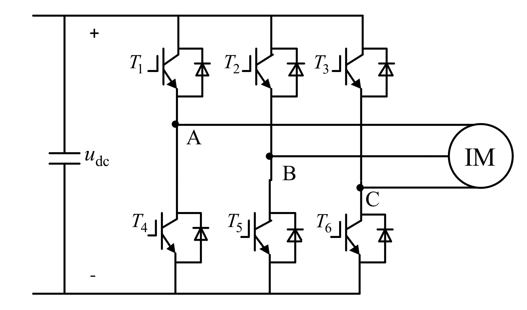
The inverter consists of switching devices of IGBTs and diodes as shown in Figure 2, where T1-T6 are the switching elements of the three-phase inverter. Considering a balanced voltage condition, the three-phase voltage of the induction motor can be expressed as:
where usa, usb, and usc are the voltage of phase A, B, and C, respectively; Uk (k = 1, 5, 7,…) is the magnitude of the k-th harmonic; and ω1 is the angular frequency (ω1 = 2πf1) with f1 being the fundamental frequency. As observed in Equation (1), the motor voltage is a PWM voltage that contains a series of harmonics at k = 6i ± 1 (i= 0, 1, 2, 3…), whose magnitude decreases with the increasing harmonic order.
2.2. Currents of IM Under Stator Faults
When motors have stator faults, the three-phase stator windings become asymmetry. The stator current will be un-balanced, and thus, the negative-sequence current will be introduced. In this case, the motor currents are described by:
in which isa,SF, isb,SF, and isc,SF are the stator fault currents of phase A, B, and C, respectively; Ikp and Ikn are the magnitudes of the kth positive and negative harmonic currents; φkp and φkn are the phase angle of the kth positive and negative harmonic currents.
2.3. Stator Fault Components in the Torque Spectrum
According to the voltage in Equation (1) and the stator current in Equation (2), the motor voltage and current in the stationary α-β reference frame are given as:
where usα and usβ are the stator voltages in the α-β reference frame; isα and isβ are the stator currents in the α-β reference frame.
To derive the stator flux under stator faults and simplify the calculation, it is assumed that the voltage-drop caused by the stator resistance is ignored. Then, the stator flux in the stationary α-β reference frame can be expressed through the voltage integral, and then, simplified as:
in which λsα and λsβ are the stator flux in the α-β reference frame. According to [43,44], when a stator fault is present in the motor, the electromagnetic torque is calculated as:
where P is the number of poles, μ is the fault severity factor, if is the circulating fault current in the short-circuit path. In practice, it is unavailable to measure μ and if directly, and thus, the last item in (9) caused by the stator fault is neglected here. Nevertheless, the rest of Equation (9) contains fault components induced by the unbalance of three-phase currents, which are further analyzed to find fault indicators for motor condition monitoring. Accordingly, the electromagnetic torque can be approximately expressed as:
Substituting Equations (5)–(8) into Equation (10), gives:
According to the above formula, it can be found that when m = 6i + 1 (i = 0, 1, 2, …) and k = 6j + 1 (j = 0, 1, 2, …), the healthy part produces a dc component (m = k) and harmonic components (m ≠ k) with the frequencies of 6hω1 (h = 1, 2, 3, …); the fault part produces harmonic components with the frequencies of (6h + 2)ω1. Similarly, for other conditions, the (6h + 2) ω1 or (6h − 2)ω1 is generated according to the fault parts in Equation (11). In all, for a healthy motor, the negative current Ikn (k = 1, 5, 7, …) is equal to zero, and there are only a dc component and harmonics whose frequencies are 6hω1 in the torque spectrum. When the motor has stator faults, it is observed from Equation (11) that additional fault frequencies of (6h ± 2)ω1 will be produced, which can be used as indicators of the motor status.
The frequency components induced by the interaction of the fundamental, the fifth and seventh harmonics under stator faults in the torque spectrum are listed in Table 1. It can be seen from Table 1 that the fault frequencies of 2f1, 4f1, 8f1, 10f1, and 14f1 are produced in the torque spectrum. It is also observed in Table 1 that the components with frequencies of 2f1, 4f1, and 8f1 have higher magnitudes in the torque spectrum, as these frequencies components are the results of the interaction of the fundamental and harmonics. Consequently, interactive components with the frequencies of 2f1, 4f1, and 8f1 are expected to detect stator faults.
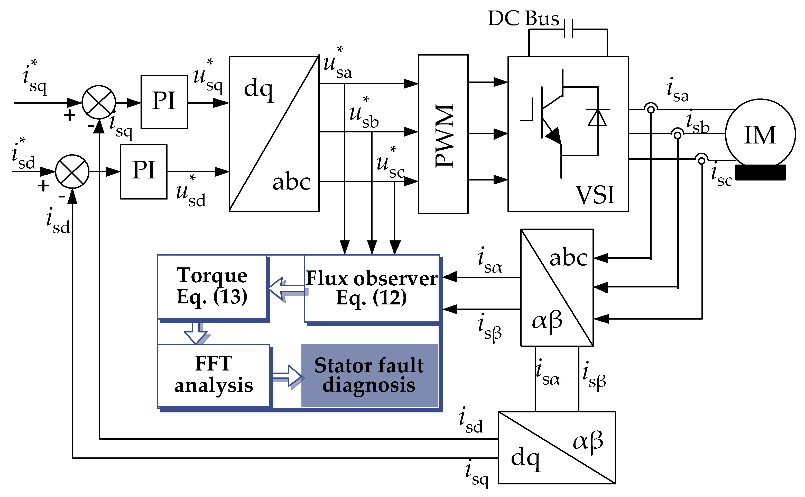
2.4. Torque Measurement
The above stator fault diagnosis method depends on the electromagnetic torque. However, the motor is usually not equipped with a torque sensor in practice. Therefore, the acquisition of the flux is crucial for the torque calculation according to (10). A full-order flux observer is very popular and employed for rotor flux estimation because of its high robustness and fast convergence. Even the IM has parameter variations, the observed current from the closed-loop observer still can track its actual value. The novel full-order flux observer is expressed as:
with
in which is the observed state variables; is the output variables; A, B, and C are the state, input, and output matrices; G is the feedback gain matrix; sα, sβ, sα, and sβ are the estimated stator current and rotor flux in the α-β reference frame; Rs, Rr, Ls, and Lr are motor resistances and inductances; σ is the total leakage coefficient; ωr is the rotor angular frequency. The elements g1 to g4 in G are defined as
where ρ (ρ > 1) determines the poles of the observer. Accordingly, the lower the pole ρ is, the slower the convergence is, whereas the more stable the observer is; on the contrary, the higher the pole ρ is, the faster convergence is, whereas the less stable the observer is. The value of ρ balances the convergence speed and stability.
The stator flux is estimated according to the observer in Equation (12), and subsequently, the torque is calculated as
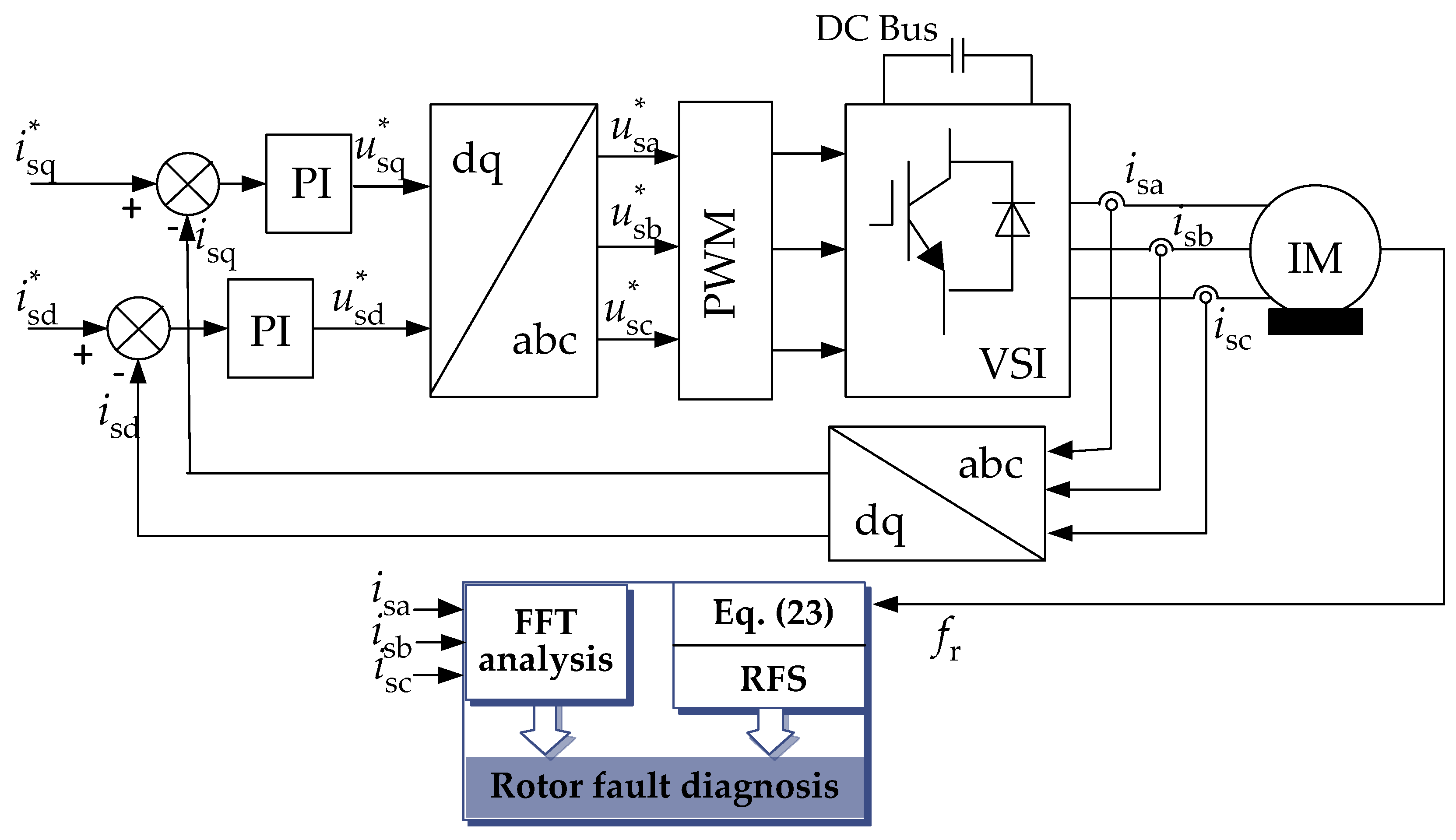
Then, the torque spectrum is obtained through the FFT method. Depending on the magnitude of the fault frequencies 2f1, 4f1, and 8f1, the monitoring of stator faults can be realized. This stator fault diagnosis procedure is illustrated in Figure 3, where PI represents a proportional-integral controller; VSI is the voltage source inverter.
3. Rotor Fault Diagnosis
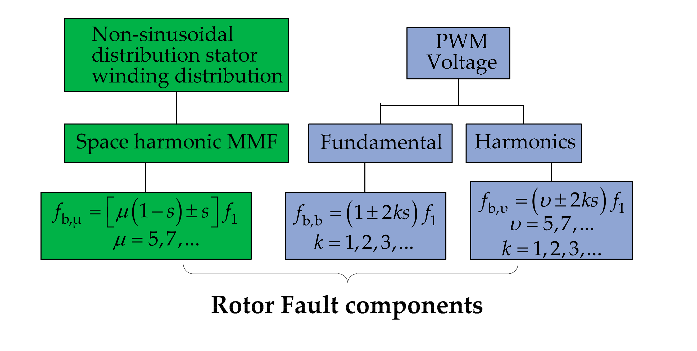
3.1. Fundamental Sidebands of Rotor Faults
Rotor faults lead to the rotor asymmetry, which produces fault components with a frequency (1 − 2s)f1 in the stator current. Then, the fault components will induce motor torque and speed ripples, and furthermore, the frequency component of (1 + 2s)f1 in the current is introduced. Eventually, sideband components with the frequency shown in Equation (14) can be used for fault detection. It is clear that the component with a higher harmonic order k has a lower current magnitude until the magnitude is close to zero, as shown in Equation (15).
3.2. Space Harmonics Sidebands of Rotor Faults
The non-sinusoidal distribution of the stator winding produces a series of space harmonic MMFs with the order being μ = 6i ± 1 (i = 1, 2, 3, …). If a rotor fault occurs, these space harmonics will produce fault components in the stator current. According to [45,46], the induced fault frequencies can be described as
where the frequencies produced by the fifth- and seventh-order space harmonics, i.e., (5 − 4s)f1, (5 − 6s)f1, (7 − 6s)f1, (7 − 8s)f1, are the largest among all the space harmonic components.
3.3. Time Harmonics Sidebands of Rotor Faults
The time-domain current harmonics of the inverter-connected healthy motor are given as
where isa,h, isb,h, and isc,h are the currents of phase A, B, and C; I1 represents the fundamental current magnitude and Iυ is the magnitude of the υth harmonic current; φ1 and φυ represent the phase angles of the fundamental and the υth harmonic current, respectively.
If a rotor fault occurs in the motor, the above time-domain harmonics will produce fault sidebands in the stator current. It is clear that the current contains harmonics with the order being υ = 6i ± 1 (i = 1, 2, 3, …). The harmonic signals rotate in the positive direction (υ = 7, 13, …) and in the negative direction (υ = 5, 11, …), as described by
Therefore, the υth time harmonics rotate at the speed of fυ that can be expressed by
where the sign of (υ − 6i) represents the rotation direction. Then, the rotation speed of harmonics with respect to the rotor can be represented by
which is the difference between fυ and the rotor speed fr = (1 − s)f1.
As a consequence, the rotor faults will produce negative sequence currents at frequencies of −fυ,r in the rotor current, which induces fb,υ = − fυ,r + fr fault components in the stator current. Therefore, the υth time harmonic produces the fault component at (υ ± 2s)f1 frequency in the stator current. Similarly, a series of time harmonic sidebands appear as
According to the aforementioned fundamental sidebands, space, and time harmonic sidebands, the rotor fault components are summarized, as shown in Figure 4, where the frequencies fb,μ, fb,b, fb,υ in the stator current spectrum are the fault features that ensure reliable monitoring of rotor faults.
3.4. Rotor Faults Diagnosis Based on MCSA
It can be observed in Equation (1) that the fifth and seventh harmonics have larger magnitudes, and thus, the rotor fault monitoring based on the detection of fault components produced by the fundamental, the fifth- and seventh-time and space harmonics with the frequencies of (1 ± 2s)f1, (5 ± 2s)f1, (5 − 4s)f1, (5 − 6s)f1, (7 ± 2s)f1, (7 − 6s)f1, and (7 − 8s)f1 is significantly advantageous. Therefore, the rotor fault is detected through the comparison of the magnitudes of these rotor fault signatures (RFS) under health and fault conditions. It should be noted that the slip s can be directly calculated by
where fr is the rotor speed that can be obtained through the speed sensor. This rotor fault diagnosis procedure is illustrated as Figure 5.
4. Experimental Results
4.1. Experimental Setup
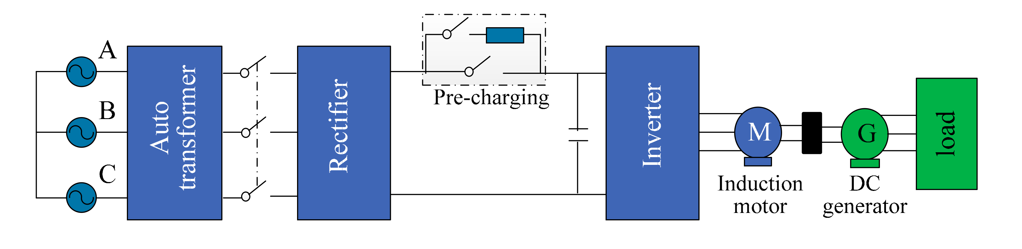
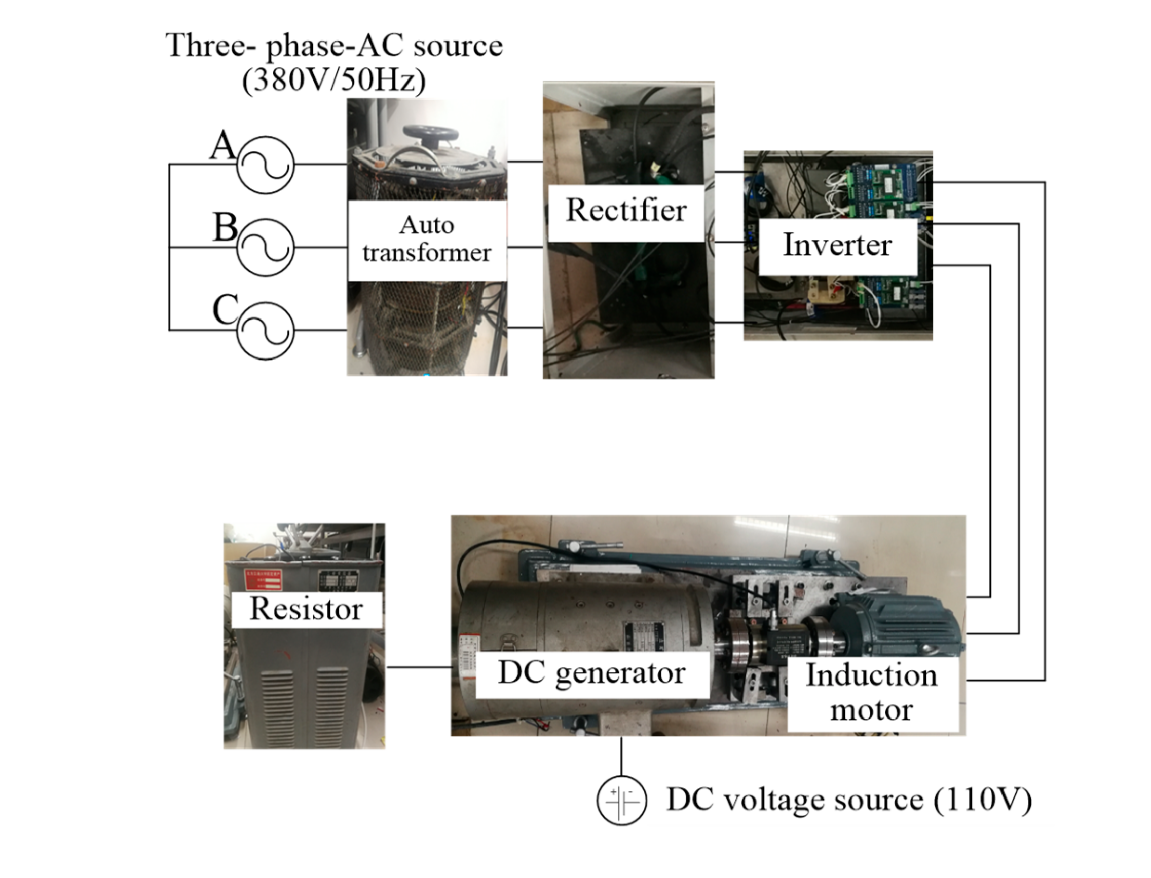
The basic schematic of the experimental setup is shown in Figure 6, where the three-phase voltage (380 V/50 Hz) is adjusted through an auto-transformer and a rectifier. Then, the dc voltage is fed to the IM through the variable-voltage and variable-frequency VSI. The load is controlled by adjusting the field voltage of a 1.5 kW dc generator coupled to the motor. The photo of entire experimental rig is shown in Figure 7. The control frequency of the IM is 2 kHz, and the switching frequency of the inverter is 1 kHz. Motor currents are measured and analyzed with a 10 kHz sampling frequency.
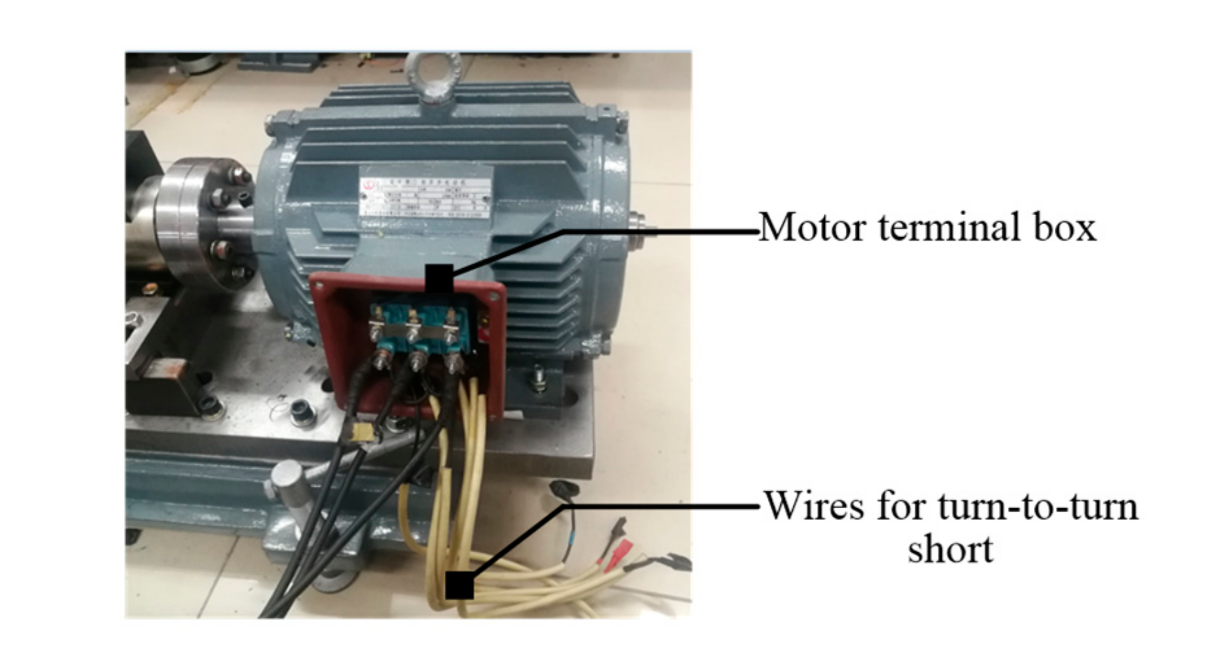
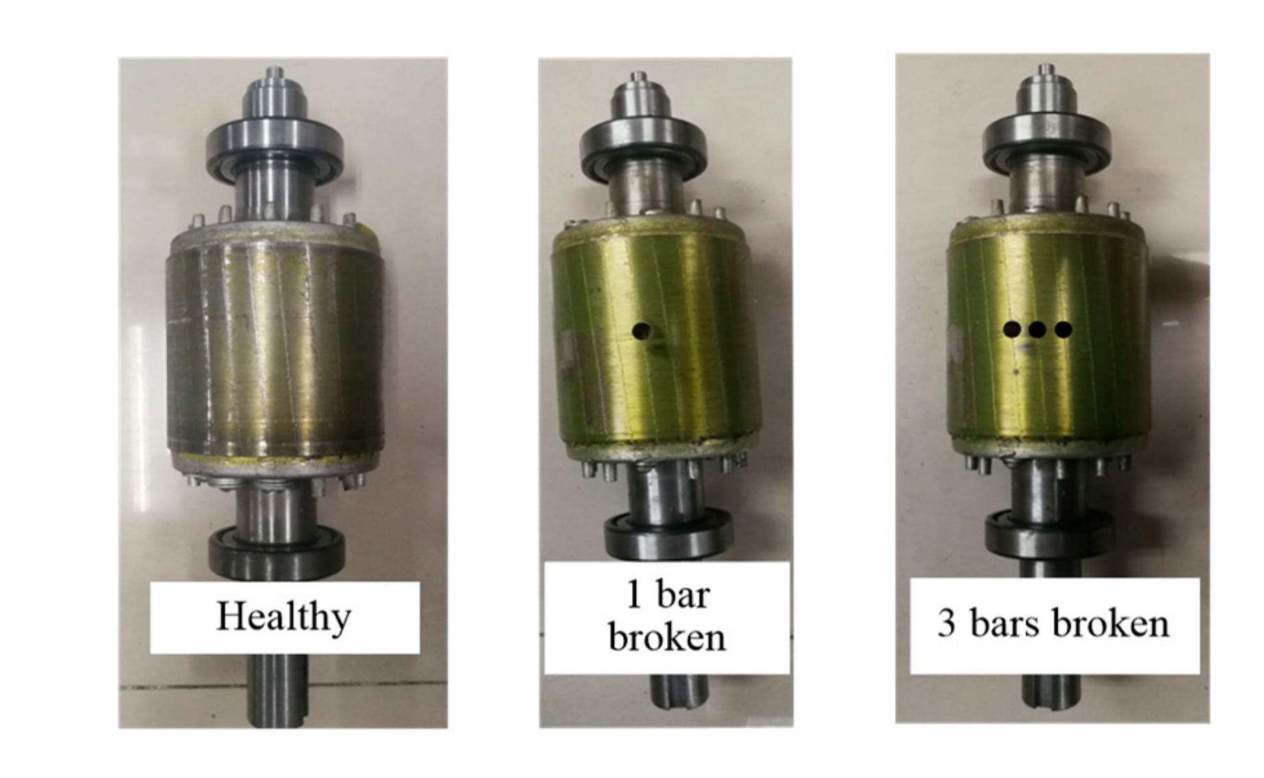
To verify the aforementioned, experimental tests are performed on the 2.2-kW/380-V/50-Hz three-phase IM system shown in Figure 6; Figure 7. The motor has 36 stator slots and 28 rotor slots, and the number of turns in each phase is 252, where there are 6 coils of windings for a stator phase, and each coil has 42 turns, as shown in Figure 8. One stator with turn-to-turn insulation failures and three rotors with broken bars are arbitrarily designed. For the fault stator, the stator winding was modified through the addition of taps connected to the stator winding turns, and the ends of these external wires are placed in the motor terminal box, as shown in Figure 9. When it needs to perform the stator inter-turn short fault tests, any two additions of the taps are collected to short-circuit several turns. For the rotor fault, the bar breakage is created by drilling holes in the contiguous aluminum bars, and then, the dynamic balance of the damaged rotors is tested and adjusted by the machine manufacturer. Photos of damaged rotors are shown in Figure 10.
4.2. Experimental Results
4.2.1. Stator Faults
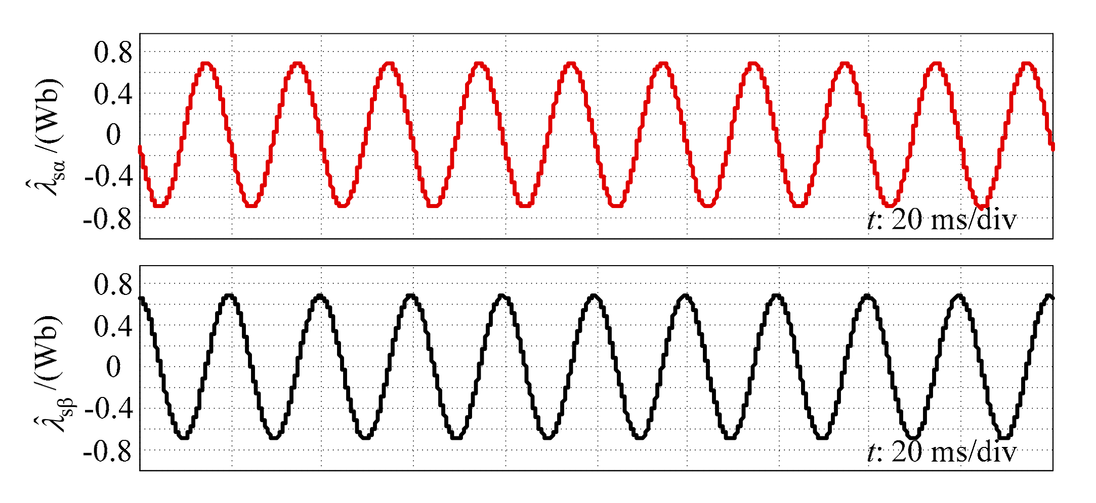
To evaluate the performance of the proposed stator fault diagnosis method, the flux should be observed for further torque calculation. The three-phase currents were measured, and the full-order flux observer was performed to obtain the flux. The results are shown in Figure 11.
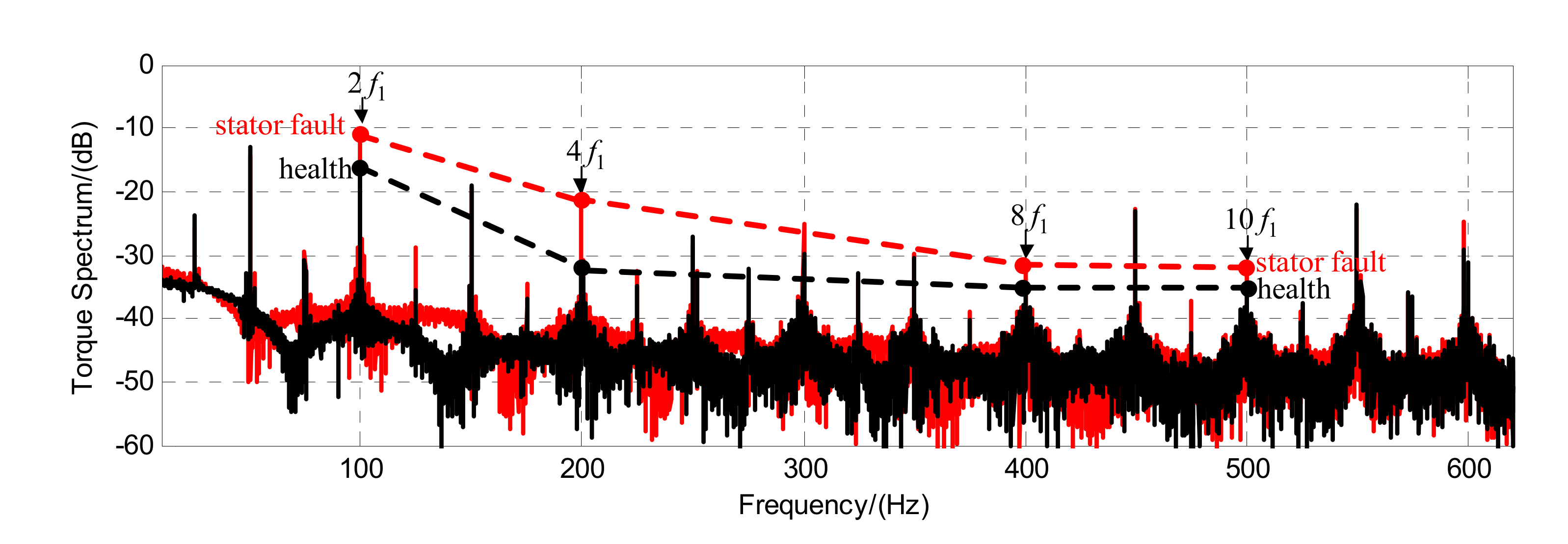
Then, the torque was calculated according to Equation (13), and the torque spectrum was analyzed. When 10 turns are short-circuited, the torque spectra of the healthy and fault stators are shown in Figure 12, which compares the magnitudes of the fault components (2f1, 4f1, 8f1, and 10f1) under healthy and fault conditions. The magnitudes of these frequencies are normalized, as illustrated in Figure 12. It can be seen from Figure 12 that the measured (2f1, 4f1, 8f1, and 10f1) components of the stator fault in the torque spectra have higher magnitudes than those of the healthy stator.
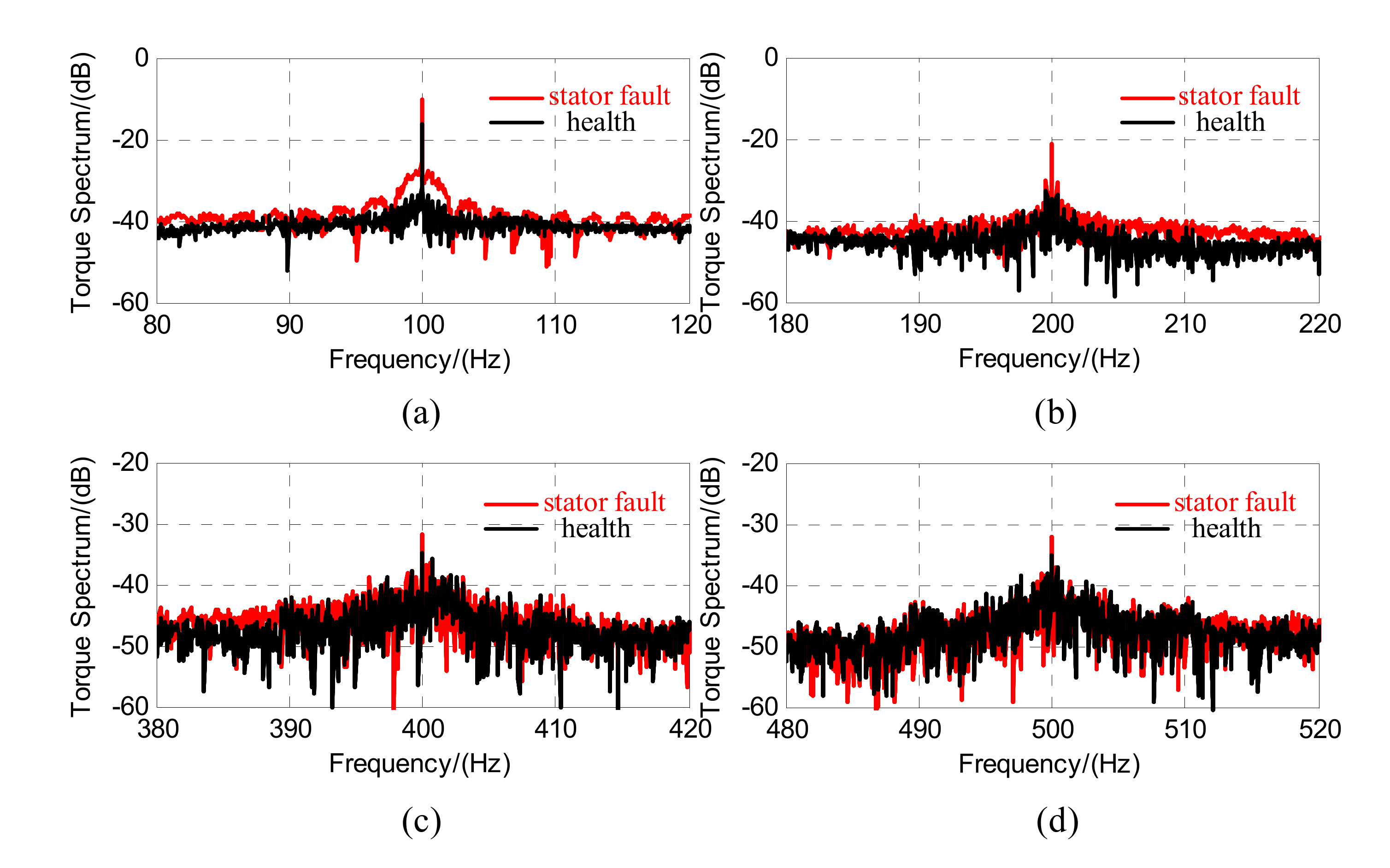
To further observe the torque spectrum, the fault frequencies (2f1, 4f1, 8f1, and 10f1) in the torque spectrum were zoomed in and shown in Figure 13. By contrast, 2f1 and 4f1 components in the torque spectrum have higher magnitudes compared to the healthy case. Thus, those can be used as the fault indicator of the stator fault. In all, the results show that the fault components with the frequencies of 2f1 and 4f1 can provide an effective stator fault detection.
4.2.2. Rotor Faults
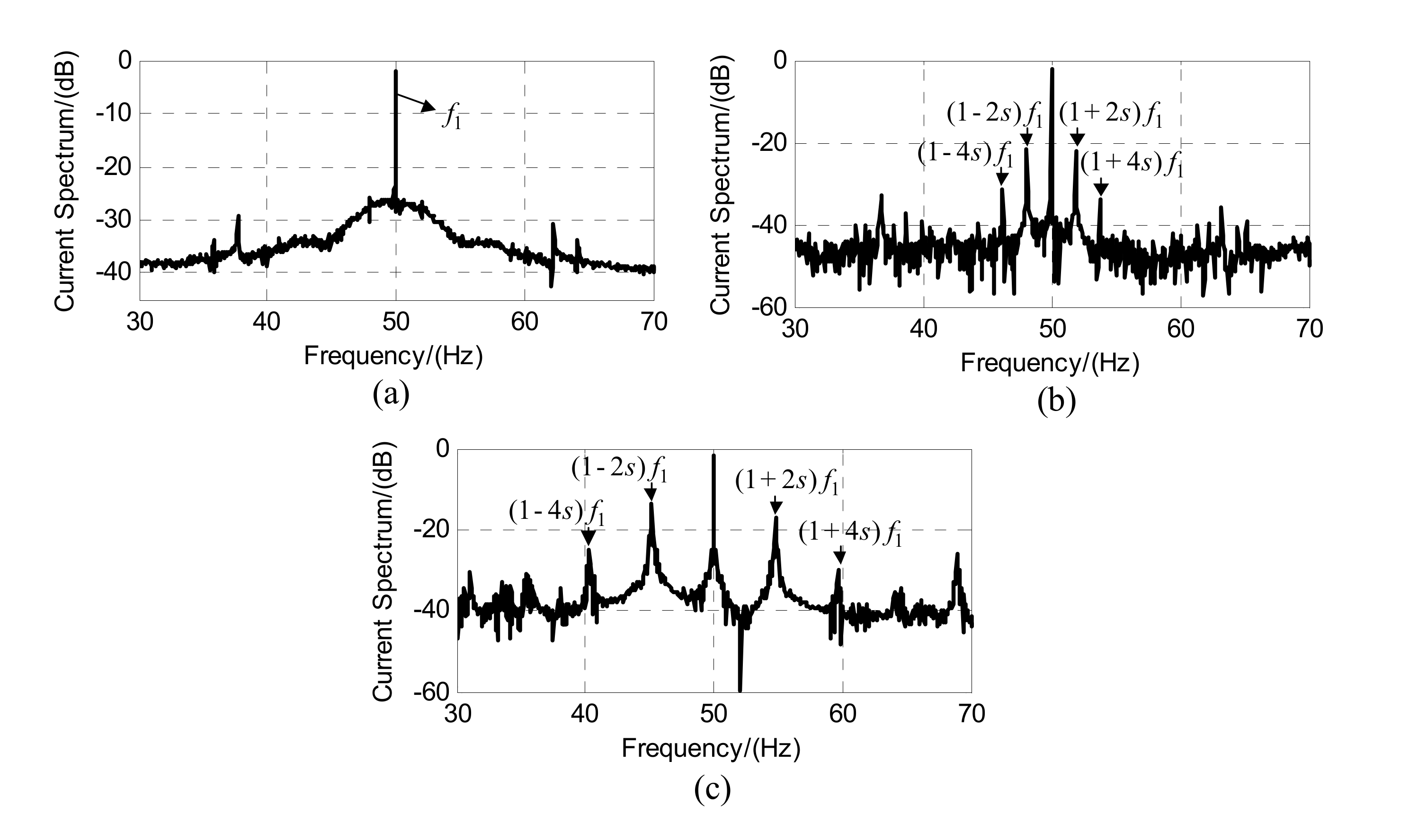
To evaluate the performance of the rotor with and without broken bars, the currents were measured firstly. Then, current spectrums are obtained and normalized. The fundamental sidebands of the currents are shown in Figure 14. It can be observed from the extra components under broken bar fault conditions in Figure 14 that the magnitudes of (1 ± 2s)f1 and (1 ± 4s)f1 components increase with the higher number of the broken bars. The results clearly show that (1 ± 2s)f1 and (1 ± 4s)f1 signatures can not only identify the healthy and fault rotors, but also can be used as an indicator of the severity of the broken bar fault.
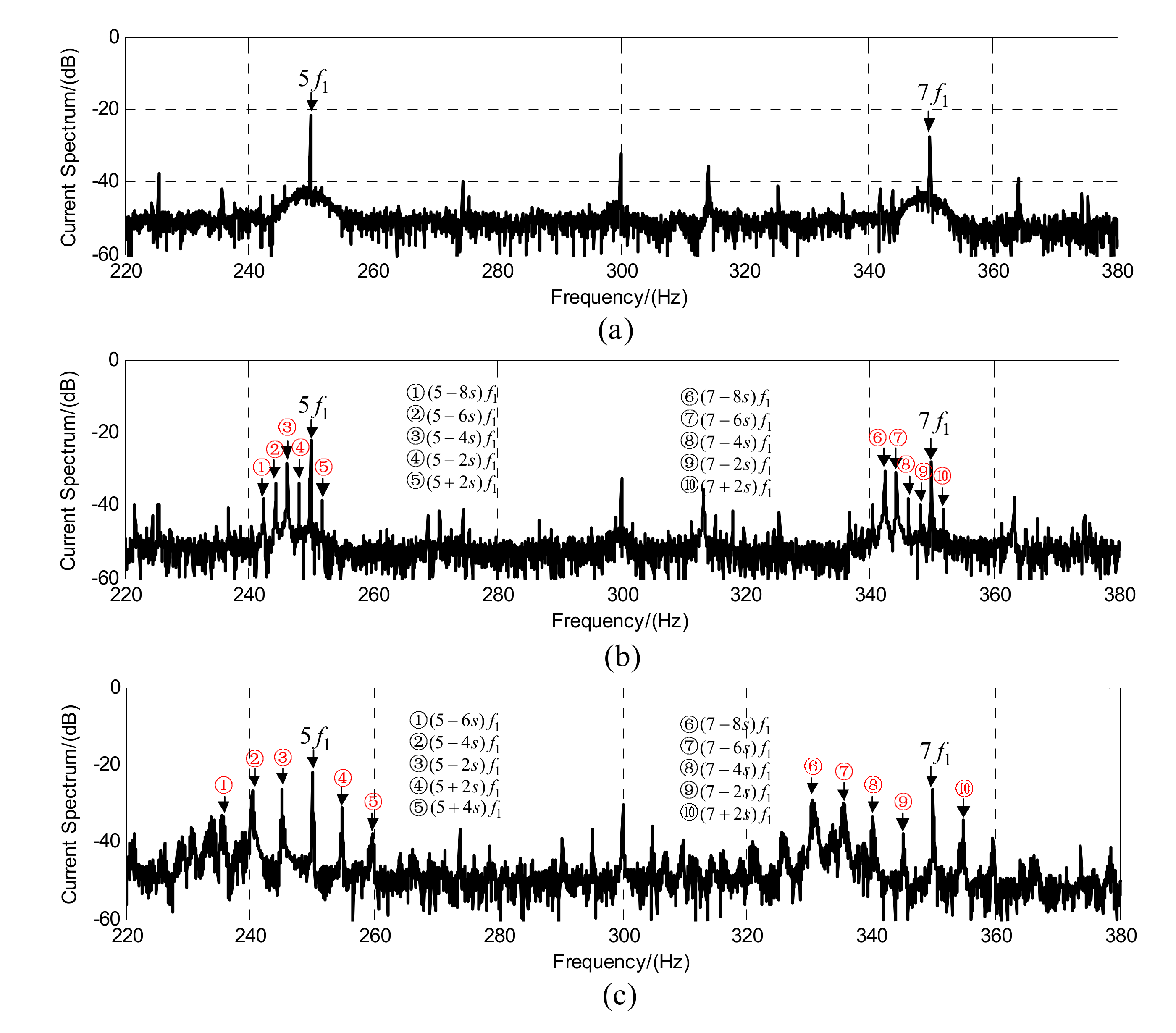
The current sidebands of the fifth and seventh harmonics include the fault components induced by space and time harmonics when the motor has rotor faults. The current spectra from 220 to 380 Hz are shown in Figure 15, where the space and time fault harmonic characterized frequencies are marked. For the healthy rotor, the magnitudes of these components are significantly smaller than those under rotor faults. As observed in Figure 15b,c, the left and right sidebands of the fifth and seventh current harmonics are significant.
It can be seen from Figure 15b that additional (5 ± 2s)f1 components are produced, and then (5 ± 4s)f1 components are induced, where the magnitude of (5 + 4s)f1 is small. This feature is not obvious in the spectrum. In theory, the (5 ± 4s)f1-components are induced by the (5 ± 2s)f1-components. Hence, the current magnitudes have a relationship of |(5 ± 4s)f1| < |(5 ± 2s)f1|. Nevertheless, it is found that the (5 − 4s)f1-current has a larger magnitude than the (5 − 2s)f1 component. This is because the (5 − 4s)f1 frequency is not only produced by the fifth time harmonic but also by the fifth space fault harmonic. It is the superposition of the fifth time and the fifth space harmonics in the current under rotor faults. In addition, the space MMF also introduces the (5 − 6s)f1 component, and then the (5 − 8s)f1-component is induced. For the seventh harmonic current sidebands, the (7 ± 2s)f1-fault components of the time harmonics are observed. The (7 − 2s)f1-component induces the (7 − 4s)f1-component. However, it can be seen that the magnitude of (7 − 4s)f1 is larger than the (7 − 2s)f1-component, which is similar to the phenomenon for the (5 − 4s)f1-component. Here, the (7 − 4s)f1-component is produced by the (7 − 2s)f1-component induced by the seventh time harmonic and the (7 − 6s)f1-component induced by the seventh space harmonic under rotor faults. Furthermore, it also can be observed the (7 − 8s)f1-component from the current spectra is in accordance with the above analysis. The results clearly show that the derived space and time fault components can be used for rotor monitoring.
Figure 15c shows that the additional fault components with the frequencies of (5 ± 2s)f1 and (5 ± 4s)f1 of the time harmonic current, and fault components of (5 − 6s)f1 and (5 − 4s)f1 of the space harmonic current are recognized. The generation of (5 − 4s)f1-component is similar to the behavior of the case of one bar broken. In addition, the (7 − 8s)f1, (7 − 6s)f1, (7 − 4s)f1, and (7 ± 2s)f1 fault components are observed in Figure 15c, which can provide the detection information of the rotor fault. When comparing the current spectrums described in Figure 15b,c, it can be observed that the magnitude of the individual fault component increases with a high number of broken bars. The results show that the derived sidebands have a significant increase in the current spectrum when a rotor fault is presented, which can provide an effective monitoring of the rotor fault.
5. Conclusions
Reliable fault diagnosis is important for high-performance inverter-fed IMs. This paper thus proposed novel fault diagnosis methods for IMs under stator and rotor faults, considering the harmonics in the currents. The diagnosis is achieved based on the fault characteristics. That is, for stator faults, the corresponding fault components are obtained in the torque spectrum; for rotor faults, the time and space harmonic sidebands are characterized in the currents. Experimental tests on an inverter-fed 2.2 kW/380 V/50 Hz IM have been provided. The test results have verified the effectiveness of the proposed methods and the analysis. In a word, the characterized fault components under the rotor and stator faults in this paper can be used for the reliable detection of stator and rotor faults for IMs.
Author Contributions
All authors contributed equally to this paper. All authors have read and agreed to the published version of the manuscript.
Funding
This research was funded by the Fundamental Research Funds for the Central Universities (2018JBZ004).
Acknowledgments
The author would like to thank the editor and the reviewers who provided many helpful comments and thereby contributed to the final manuscript.
Conflicts of Interest
The authors declare no conflict of interest.
References
- Wu, W.; Wu, X.; Yin, J.; Jing, L.; Wang, S.; Li, J. Characteristic Analysis and Fault-Tolerant Control of Circulating Current for Modular Multilevel Converters under Sub-Module Faults. Energies 2017, 10, 1827. [Google Scholar] [CrossRef] [Green Version]
- Li, W.; Li, G.; Zeng, R.; Ni, K.; Hu, Y.; Wen, H. The Fault Detection, Localization, and Tolerant Operation of Modular Multilevel Converters with an Insulated Gate Bipolar Transistor (IGBT) Open Circuit Fault. Energies 2018, 11, 837. [Google Scholar] [CrossRef] [Green Version]
- Salomon, C.P.; Ferreira, C.; Sant’Ana, W.C.; Lambert-Torres, G.; Borges da Silva, L.E.; Bonaldi, E.L.; de Oliveira, L.E.L.; Torres, B.S. A Study of Fault Diagnosis Based on Electrical Signature Analysis for Synchronous Generators Predictive Maintenance in Bulk Electric Systems. Energies 2019, 12, 1506. [Google Scholar] [CrossRef] [Green Version]
- Ullah, Z.; Hur, J. A Comprehensive Review of Winding Short Circuit Fault and Irreversible Demagnetization Fault Detection in PM Type Machines. Energies 2018, 11, 3309. [Google Scholar] [CrossRef] [Green Version]
- Candelo-Zuluaga, C.; Riba, J.-R.; López-Torres, C.; Garcia, A. Detection of Inter-Turn Faults in Multi-Phase Ferrite-PM Assisted Synchronous Reluctance Machines. Energies 2019, 12, 2733. [Google Scholar] [CrossRef] [Green Version]
- Gao, C.; Nie, Y.; Si, J.; Fu, Z.; Feng, H. Mode Recognition and Fault Positioning of Permanent Magnet Demagnetization for PMSM. Energies 2019, 12, 1644. [Google Scholar] [CrossRef] [Green Version]
- Gao, H.; Zhang, W.; Wang, Y.; Chen, Z. Fault-Tolerant Control Strategy for 12-Phase Permanent Magnet Synchronous Motor. Energies 2019, 12, 3462. [Google Scholar] [CrossRef] [Green Version]
- Gonçalves, P.; Cruz, S.; Mendes, A. Finite Control Set Model Predictive Control of Six-Phase Asymmetrical Machines—An Overview. Energies 2019, 12, 4693. [Google Scholar] [CrossRef] [Green Version]
- Siddique, A.; Yadava, G.S.; Singh, B. A review of stator fault monitoring techniques of induction motors. IEEE Trans. Energy Convers. 2005, 20, 106–114. [Google Scholar] [CrossRef]
- Motor Reliability Working Group. Report of large motor reliability survey of industrial and commercial installations, part I. IEEE Trans. Ind. Appl. 1985, IA-21, 853–864. [Google Scholar] [CrossRef]
- Benbouzid, M.E.H. A review of induction motors signature analysis as a medium for faults detection. In Proceedings of the 24th Annual Conference of the IEEE Industrial Electronics Society (Cat. No.98CH36200), Aachen, Germany, 31 August–4 September 1998; pp. 1950–1955. [Google Scholar] [CrossRef]
- Sun, L.; Xu, B. An Improved Method for Discerning Broken Rotor Bar Fault and Load Oscillation in Induction Motors. Energies 2018, 11, 3130. [Google Scholar] [CrossRef] [Green Version]
- Nemec, M.; Ambrožič, V.; Fišer, R.; Nedeljković, D.; Drobnič, K. Induction Motor Broken Rotor Bar Detection Based on Rotor Flux Angle Monitoring. Energies 2019, 12, 794. [Google Scholar] [CrossRef] [Green Version]
- Riera-Guasp, M.; Antonino-Daviu, J.A.; Capolino, G. Advances in Electrical Machine, Power Electronic, and Drive Condition Monitoring and Fault Detection: State of the Art. IEEE Trans. Ind. Electron. 2015, 62, 1746–1759. [Google Scholar] [CrossRef]
- Marques Cardoso, A.J.; Cru, S.M.A.Z.; Fonseca, D.S.B. Inter-turn stator winding fault diagnosis in three-phase induction motors, by Park’s vector approach. IEEE Trans. Energy Convers. 1999, 14, 595–598. [Google Scholar] [CrossRef]
- Benbouzid, M.E.H.; Kliman, G.B. What stator current processing-based technique to use for induction motor rotor faults diagnosis? IEEE Trans. Energy Convers. 2003, 18, 238–244. [Google Scholar] [CrossRef] [Green Version]
- Cruz, S.M.; Cardoso, A.A.J.M. Stator winding fault diagnosis in three-phase synchronous and asynchronous motors, by the extended Park’s vector approach. IEEE Trans. Ind. Appl. 2001, 37, 1227–1233. [Google Scholar] [CrossRef]
- Eftekhari, M.; Moallem, M.; Sadri, S.; Hsieh, M. Online Detection of Induction Motor’s Stator Winding Short-Circuit Faults. IEEE Syst. J. 2014, 8, 1272–1282. [Google Scholar] [CrossRef]
- Cheng, S.; Zhang, P.; Habetler, T.G. An Impedance Identification Approach to Sensitive Detection and Location of Stator Turn-to-Turn Faults in a Closed-Loop Multiple-Motor Drive. IEEE Trans. Ind. Electron. 2011, 58, 1545–1554. [Google Scholar] [CrossRef]
- Puche-Panadero, R.; Pineda-Sanchez, M.; Riera-Guasp, M.; Roger-Folch, J.; Hurtado-Perez, E.; Perez-Cruz, J. Improved Resolution of the MCSA Method Via Hilbert Transform, Enabling the Diagnosis of Rotor Asymmetries at Very Low Slip. IEEE Trans. Energy Convers. 2009, 24, 52–59. [Google Scholar] [CrossRef]
- Pezzani, C.; Donolo, P.; Bossio, G.; Donolo, M.; Guzmán, A.; Zocholl, S.E. Detecting Broken Rotor Bars With Zero-Setting Protection. IEEE Trans. Ind. Appl. 2014, 50, 1373–1384. [Google Scholar] [CrossRef]
- Douglas, H.; Pillay, P.; Ziarani, A.K. Broken Rotor Bar Detection in Induction Machines With Transient Operating Speeds. IEEE Trans. Energy Convers. 2005, 20, 135–141. [Google Scholar] [CrossRef]
- Xu, B.; Sun, L.; Xu, L.; Xu, G. An ESPRIT-SAA-Based Detection Method for Broken Rotor Bar Fault in Induction Motors. IEEE Trans. Energy Convers. 2012, 27, 654–660. [Google Scholar] [CrossRef]
- Xu, B.; Sun, L.; Xu, L.; Xu, G. Improvement of the Hilbert Method via ESPRIT for Detecting Rotor Fault in Induction Motors at Low Slip. IEEE Trans. Energy Convers. 2012, 27, 654–660. [Google Scholar] [CrossRef]
- Benbouzid, M.E.H.; Vieira, M.; Theys, C. Induction motors faults detection and localization using stator current advanced signal processing techniques. IEEE Trans. Power Electron. 1999, 14, 14–22. [Google Scholar] [CrossRef]
- Kia, S.H.; Henao, H.; Capolino, G. A High-Resolution Frequency Estimation Method for Three-Phase Induction Machine Fault Detection. IEEE Trans. Ind. Electron. 2007, 54, 2305–2314. [Google Scholar] [CrossRef]
- Jerkan, D.G.; Reljić, D.D.; Marčetić, D.P. Broken Rotor Bar Fault Detection of IM Based on the Counter-Current Braking Method. IEEE Trans. Energy Convers. 2017, 32, 1356–1366. [Google Scholar] [CrossRef]
- Antonino-Daviu, J.A.; Quijano-López, A.; Rubbiolo, M.; Climente-Alarcon, V. Advanced analysis of motor currents for the diagnosis of the rotor condition in electric motors operating in mining facilities. IEEE Trans. Ind. Appl. 2018, 54, 3934–3942. [Google Scholar] [CrossRef]
- CusidÓCusido, J.; Romeral, L.; Ortega, J.A.; Rosero, J.A.; GarcÍaGarcia Espinosa, A. Fault Detection in Induction Machines Using Power Spectral Density in Wavelet Decomposition. IEEE Trans. Ind. Electron. 2008, 55, 633–643. [Google Scholar] [CrossRef]
- Pons-Llinares, J.; Antonino-Daviu, J.A.; Riera-Guasp, M.; Bin Lee, S.; Kang, T.; Yang, C. Advanced Induction Motor Rotor Fault Diagnosis Via Continuous and Discrete Time–Frequency Tools. IEEE Trans. Ind. Electron. 2015, 62, 1791–1802. [Google Scholar] [CrossRef]
- Antonino-Daviu, J.A.; Pons-Llinares, J.; Lee, S.B. Advanced Rotor Fault Diagnosis for Medium-Voltage Induction Motors Via Continuous Transforms. IEEE Trans. Ind. Appl. 2016, 52, 4503–4509. [Google Scholar] [CrossRef]
- Climente-Alarcon, V.; Antonino-Daviu, J.A.; Riera-Guasp, M.; Vlcek, M. Induction Motor Diagnosis by Advanced Notch FIR Filters and the Wigner–Ville Distribution. IEEE Trans. Ind. Electron. 2014, 61, 4217–4227. [Google Scholar] [CrossRef] [Green Version]
- Chow, M.-Y.; Mangum, P.M.; Yee, S.O. A neural network approach to real-time condition monitoring of induction motors. IEEE Trans. Ind. Electron. 1991, 38, 448–453. [Google Scholar] [CrossRef]
- Ghate, V.N.; Dudul, S.V. Cascade Neural-Network-Based Fault Classifier for Three-Phase Induction Motor. IEEE Trans. Ind. Electron. 2011, 58, 1555–1563. [Google Scholar] [CrossRef]
- Sadeghian, A.; Ye, Z.; Wu, B. Online Detection of Broken Rotor Bars in Induction Motors by Wavelet Packet Decomposition and Artificial Neural Networks. IEEE Trans. Instrum. Meas. 2009, 58, 2253–2263. [Google Scholar] [CrossRef]
- Seera, M.; Lim, C.P.; Ishak, D.; Singh, H. Fault Detection and Diagnosis of Induction Motors Using Motor Current Signature Analysis and a Hybrid FMM–CART Model. IEEE Trans. Neural Netw. Learn. Syst. 2012, 23, 97–108. [Google Scholar] [CrossRef]
- Yagami, Y.; Araki, C.; Mizuno, Y.; Nakamura, H. Turn-to-turn insulation failure diagnosis of stator winding of low voltage induction motor with the aid of support vector machine. IEEE Trans. Dielectr. Electr. Insul. 2015, 22, 3099–3106. [Google Scholar] [CrossRef]
- Keskes, H.; Braham, A. Recursive Undecimated Wavelet Packet Transform and DAG SVM for Induction Motor Diagnosis. IEEE Trans. Ind. Informat. 2015, 11, 1059–1066. [Google Scholar] [CrossRef]
- Godoy, W.F.; da Silva, I.N.; Goedtel, A.; Cunha Palácios, R.H.; Lopes, T.D. Application of intelligent tools to detect and classify broken rotor bars in three-phase induction motors fed by an inverter. IET Electr. Power App. 2016, 10, 430–439. [Google Scholar] [CrossRef]
- Martin-Diaz, I.; Morinigo-Sotelo, D.; Duque-Perez, O.; Romero-Troncoso, R.J. An Experimental Comparative Evaluation of Machine Learning Techniques for Motor Fault Diagnosis Under Various Operating Conditions. IEEE Trans. Ind. Appl. 2018, 54, 2215–2224. [Google Scholar] [CrossRef]
- Bachir, S.; Tnani, S.; Trigeassou, J.-C.; Champenois, G. Diagnosis by parameter estimation of stator and rotor faults occuring in induction machines. IEEE Trans. Ind. Electron. 2006, 53, 963–973. [Google Scholar] [CrossRef]
- Bazine, I.B.A.; Tnani, S.; Poinot, T.; Champenois, G.; Jelassi, K. On-line detection of stator and rotor faults occurring in induction machine diagnosis by parameters estimation. In Proceedings of the 8th IEEE Symposium on Diagnostics for Electrical Machines, Power Electronics & Drives, Bologna, Italy, 5–8 September 2011; pp. 105–112. [Google Scholar] [CrossRef]
- Tallam, R.M.; Habetler, T.G.; Harley, R.G. Transient model for induction machines with stator winding turn faults. IEEE Trans. Ind. Appl. 2002, 38, 632–637. [Google Scholar] [CrossRef]
- Berzoy, A.; Mohammed, O.A.; Restrepo, J. Analysis of the Impact of Stator Interturn Short-Circuit Faults on Induction Machines Driven by Direct Torque Control. IEEE Trans. Energy Convers. 2018, 33, 1463–1474. [Google Scholar] [CrossRef]
- Kim, J.; Shin, S.; Lee, S.B.; Gyftakis, K.N.; Drif, M.; Cardoso, A.J.M. Power Spectrum-Based Detection of Induction Motor Rotor Faults for Immunity to False Alarms. IEEE Trans. Energy Convers. 2015, 30, 1123–1132. [Google Scholar] [CrossRef]
- Kim, H.; Lee, S.B.; Park, S.; Kia, S.H.; Capolino, G. Reliable Detection of Rotor Faults Under the Influence of Low-Frequency Load Torque Oscillations for Applications With Speed Reduction Couplings. IEEE Trans. Ind. Appl. 2016, 52, 1460–1468. [Google Scholar] [CrossRef]
Figure 1.
Motor faults classification.

Figure 2.
A typical three-phase voltage source inverter for induction motors (IMs), where udc is the DC voltage.
Figure 2.
A typical three-phase voltage source inverter for induction motors (IMs), where udc is the DC voltage.

Figure 3.
Proposed stator fault diagnosis procedure implemented in the entire control of the IM.

Figure 4.
Rotor Fault Components in the Stator Current for Fault Monitoring.

Figure 5.
Proposed Rotor Fault Diagnosis Procedure Based on the MCSA.

Figure 6.
Schematic of the Experimental System.

Figure 7.
Experimental Test-Rig.

Figure 8.
Windings of a Phase for the Stator Turn-to-Turn Short.

Figure 9.
Photos of the Motor with a Stator Turn-to-Turn Short-Circuit Fault.

Figure 10.
Photos of the Rotors with Holes.

Figure 11.
Observed Flux in the Experiments through the Measured Three-Phase Currents for Further Torque Calculation.
Figure 11.
Observed Flux in the Experiments through the Measured Three-Phase Currents for Further Torque Calculation.

Figure 12.
Torque Spectrum Showing from 0 to 600 Hz for the Healthy and Fault Stator.

Figure 13.
Zoom-in individual stator fault components: (a) Torque spectrum of 2f1, (b) torque spectrum of 4f1, (c) torque spectrum of 8f1, and (d) torque spectrum of 10f1.
Figure 13.
Zoom-in individual stator fault components: (a) Torque spectrum of 2f1, (b) torque spectrum of 4f1, (c) torque spectrum of 8f1, and (d) torque spectrum of 10f1.

Figure 14.
Fundamental Current Sidebands Without and With Broken Bars: (a) Healthy, (b) one broken bar, and (c) three broken bars.
Figure 14.
Fundamental Current Sidebands Without and With Broken Bars: (a) Healthy, (b) one broken bar, and (c) three broken bars.

Figure 15.
Fifth and Seventh Current Sidebands Without and With Broken Bars: (a) Healthy, (b) one broken bar, and (c) three broken bars.
Figure 15.
Fifth and Seventh Current Sidebands Without and With Broken Bars: (a) Healthy, (b) one broken bar, and (c) three broken bars.


Table 1.
Stator Fault Components Induced by the Fundamental, Fifth, and Seventh Harmonics in Torque.
Table 1.
Stator Fault Components Induced by the Fundamental, Fifth, and Seventh Harmonics in Torque.
| Harmonics | Torque Spectrum | ||
|---|---|---|---|
| Health Components | Fault Components | ||
| f1 (m = 1) | f1 (k = 1) | dc | 2f1 |
| 5f1 (k = 5) | 6f1 | 4f1 | |
| 7f1 (k = 7) | 6f1 | 8f1 | |
| 5f1 (m = 5) | f1 (k = 1) | 6f1 | 4f1 |
| 5f1 (k = 5) | dc | 10f1 | |
| 7f1 (k = 7) | 12f1 | 2f1 | |
| 7f1 (m = 7) | f1 (k = 1) | 6f1 | 8f1 |
| 5f1 (k = 5) | 12f1 | 2f1 | |
| 7f1 (k = 7) | dc | 14f1 | |
© 2019 by the authors. Licensee MDPI, Basel, Switzerland. This article is an open access article distributed under the terms and conditions of the Creative Commons Attribution (CC BY) license (http://creativecommons.org/licenses/by/4.0/).
Share and Cite
MDPI and ACS Style
Tang, J.; Yang, Y.; Chen, J.; Qiu, R.; Liu, Z. Characteristics Analysis and Measurement of Inverter-Fed Induction Motors for Stator and Rotor Fault Detection. Energies 2020, 13, 101. https://doi.org/10.3390/en13010101
AMA Style
Tang J, Yang Y, Chen J, Qiu R, Liu Z. Characteristics Analysis and Measurement of Inverter-Fed Induction Motors for Stator and Rotor Fault Detection. Energies. 2020; 13(1):101. https://doi.org/10.3390/en13010101
Chicago/Turabian StyleTang, Jing, Yongheng Yang, Jie Chen, Ruichang Qiu, and Zhigang Liu. 2020. "Characteristics Analysis and Measurement of Inverter-Fed Induction Motors for Stator and Rotor Fault Detection" Energies 13, no. 1: 101. https://doi.org/10.3390/en13010101
Note that from the first issue of 2016, this journal uses article numbers instead of page numbers. See further details here.