1. Introduction
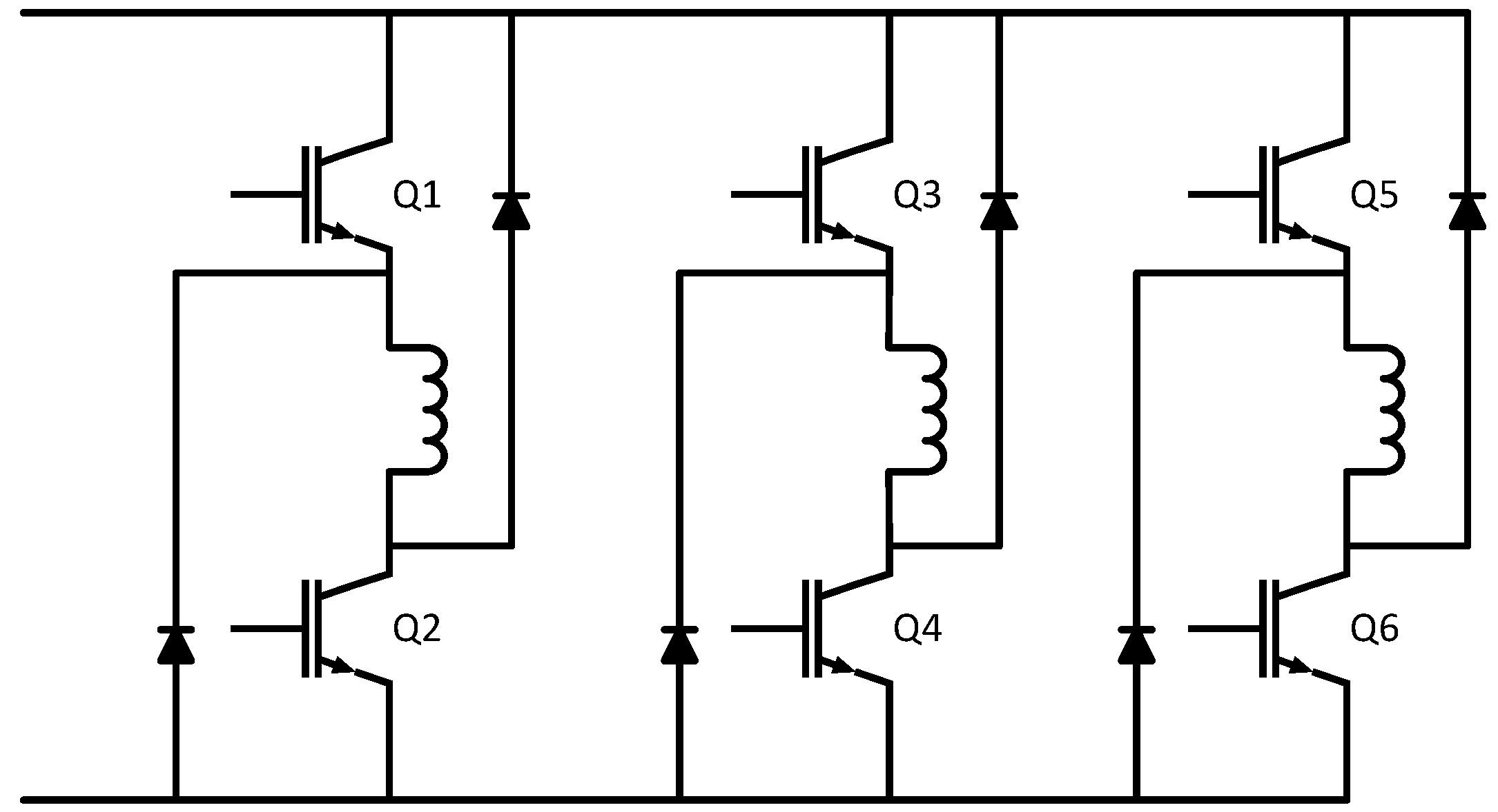
Switched reluctance motors (SRMs) are usually controlled via asymmetric H-bridges. The conventional power converter topology for a switched reluctance motor can be found in
Figure 1. Though it is a commonly used driving circuit for SRMs, six diode transistor legs are required in the traditional topology with a minimum number of eight contacts (two for supplies and six for outputs); there are also some disadvantages: one switch is always in the current conduction path, thus increasing the losses in the converter, requiring a larger heat sink for cooling, and causing a reduction of the system efficiency: two switches are always in series with the motor winding, which increases the conduction loss [
1]. Apart from the technical drawbacks, there is also a cost issue: asymmetric H-bridges are usually not mass produced and are, therefore, more expensive than standard full bridge converters.
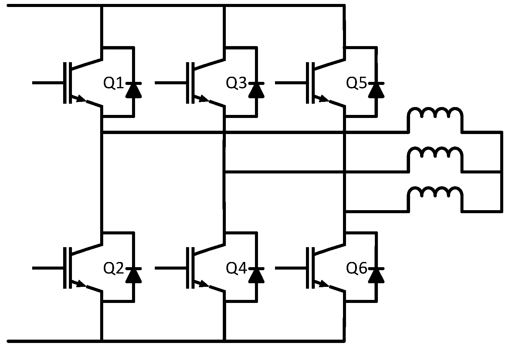
Figure 2 describes a conventional full bridge inverter, which is standard for driving induction motor and synchronous motors (permanent magnetic (PM) or excited). This type of converter, can reach high voltages with low harmonics without the use of transformers or series-connected synchronized switching devices [
2]; it can also easily provide the high power required for a large electric drive [
3]. With a multilevel topology, the synthesized output waveform of the full bridge inverter has more steps, which produces a staircase wave that approaches a desired waveform; and the harmonic distortion of the output wave decreases, approaching zero as the number of levels increases. The voltage that can be spanned by summing multiple voltage levels also increases [
3], as a result, the multilevel full bridge inverter is a structure that has no voltage sharing problems for series of connected devices are encountered [
3]. It can also obtain improved power quality, lower switching losses, and higher voltage capability [
4]; and a better electromagnetic compatibility is also obtained by a design which has less parasitic inductances [
4].
It is commonly known that a standard inverter cannot be used for driving SRMs, because of the unique operating principles of SRMs: the varying magnetic reluctance of the machine creates a force that attempts to align the rotor pole with the nearest stator pole. In order to maintain rotation, the sign of all the winding currents should be kept the same, though it does not matter to choose a positive or negative value for the current.
In order to improve the performance of the SRM converter topology, many researchers have tried to find the solution to drive an SRM by a standard inverter [
5,
6,
7,
8,
9,
10,
11,
12]. All the existing novel designs can be divided into two groups: changing the structure or topology of the SRM and changing the excitation method. The following paragraphs give an overview of the literature first for changing the structure, and then for changing the excitation.
The authors in Reference [
5] present a solution in the first group. They designed a mutually coupled SRM. By changing the structure of the phase windings, two phases can be conducted at the same time. Thus, the bipolar excitation can produce positive electromagnetic torque for this type of SRM with modified windings, and a standard three-phase inverter can generate the bipolar excitation. Actually, the machine becomes a synchronous reluctance machine, the main idea for its operation is a rotating magnetic field, which does not exist in a conventional SRM.
A novel dual-channel SRM was designed in Reference [
6], which changes the winding configuration of the SRM so that the magnetic polarity on the stator poles is different from the conventional SRM. By using two three-phase standard inverters, the new SRM can be driven, which corresponds also in fact to three single-phase H bridges.
For the second group—changing the excitation—References [
7,
8] present a four-phase SRM converter with a different topology, with an extra DC-link current sensor and a single-current sampling resistance, resulting in four transistor-diode legs, but with a compromise of efficiency. The new design can contribute to fault diagnosing and decreasing the cost of SRM controller, and the main ideas were still the improvement of conventional asymmetric H-bridges.
Reference [
9] proposed a novel single-stage power factor corrected drive for SRMs, which combines a DC link capacitor used as direct current (DC) source and a diode used for driving the motor into one power stage with conventional asymmetric H-bridges. It has a simple structure and a low cost. In fact, it is still an improvement on the conventional power converter for SRMs.
Another topology is described in Reference [
10]. The novel excitation method in this paper can drive the bipolar SRM with a three-phase H-bridge inverter. For each phase, during the working period, there should be 12 transistor drivers working for it at the same time, instead of six for the conventional asymmetric H-bridge solution. This causes a more complex solution, as four switches must be controlled per phase, but the advantage is the torque ripple and iron loss are significantly reduced with sinusoidal bipolar excitation, albeit with reduced torque capability, and if metal-oxide-semiconductor field-effect transistors (MOSFETs) are used, the on-state voltage of which (0.25 V) can be less than a diode drop (0.7 V).
Reference [
11] describes a delta-connected three-phase synchronous reluctance motor that can be driven by a standard three-phase inverter. In this inverter, three voltage pulses are applied in phase in all three stator windings in a stationary condition, by turning on and turning off the different switches. Because of the difference between an SRM and a synchronous reluctance motor, it still cannot prove that the conventional SRM can be driven by a standard inverter.
The authors of Reference [
12] use an SRM converter that combines two three-phase insulated gate bipolar transistor (IGBT) inverters and a one-leg IGBT power module. This power converter is used to drive an 8/6 SRM. In fact, it is still a variant of asymmetric H-bridges by changing the position of the corresponding used devises in the circuit.
In conclusion, apart from the methods of the first group that need to change the structure of SRMs, the three existing methods of the second group that changes the excitation method all use at least two standard inverters, excite one phase with at least four switches or add some other components to build a variant of the conventional asymmetrical half-bridge converter.
In this paper, a circulating current control method is proposed. It is a new drive topology that combines a conventional off-the-shelf, three-phase SRM with a conventional three-phase full transistor bridge structure. By using the ring structure and controlling the circulating current via a DC source, the standard inverter can be applied in the SRM driving system. The proposed idea in this paper does not need to change the structure of the SRM, which means that it can be applied in any SRM. The converter does not need more legs than the number of phases, it is also not a variant of the conventional asymmetrical half-bridge converter.
2. Theoretical Analysis of the Proposed Topology with a Conventional Three-Phase Bridge and Circulating Currents
2.1. Topology
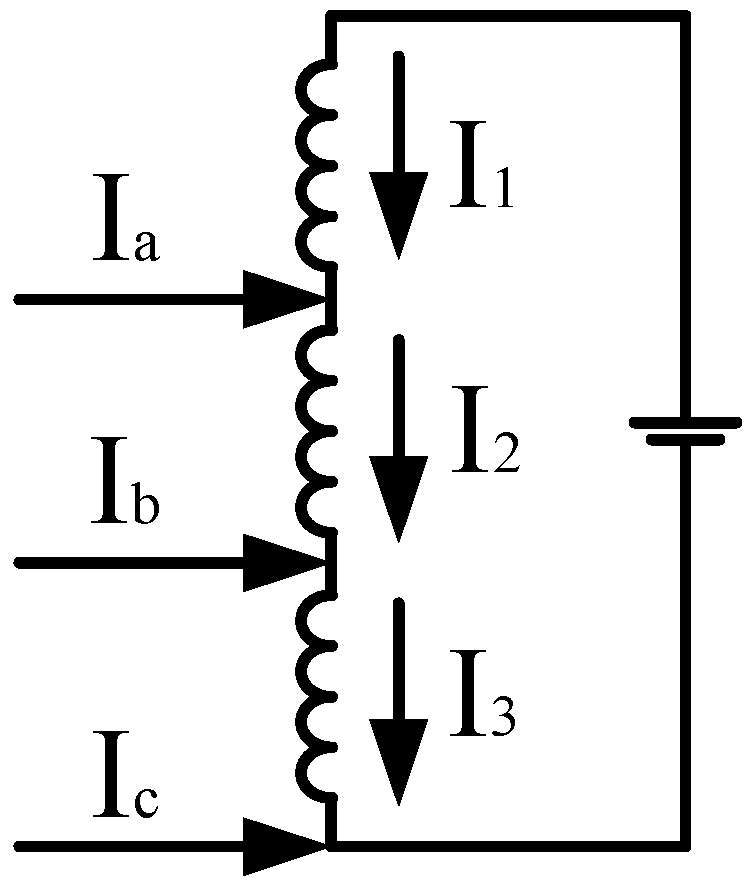
We consider a conventional SRM with three phases, e.g., a 6/4 SRM or a 12/8 SRM. The three phase windings are connected in series to form a ring structure. Many more variants are described in the corresponding patent [
13]. The ring is closed via an additional DC source. This source is a means for generating a circulating current. The injected currents
Ia,
Ib, and
Ic are produced by the conventional three-phase converter. In order to apply the additional DC power supply into the circuit, the combination of a controlled half bridge and a DC-DC buck circuit is chosen to be the alternative of the controlled voltage source. The concept of the ring structure can be found in
Figure 3.
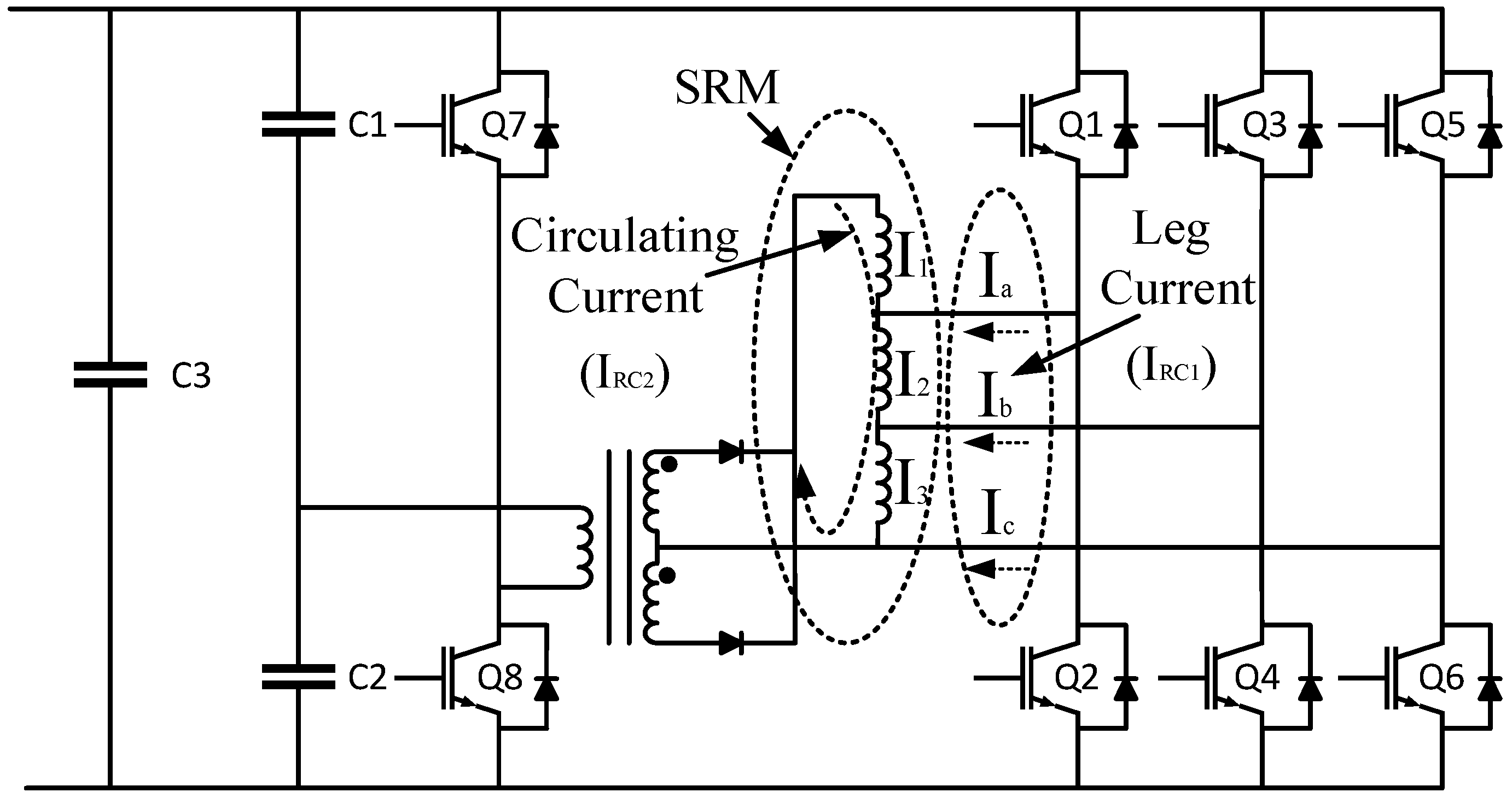
The full topology proposed is shown in
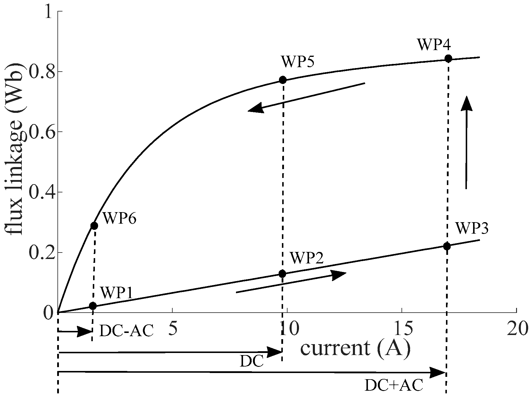
Figure 4. With the additional ring structure, the basic current in each winding can be increased, which means the “zero point” of the winding current can be increased to a higher value (9.5 A with load of 19.3 N·m, WP2 and WP5 described in
Figure 5). Thus, it is possible to keep the sign of the current in the winding positive, even with the full transistor bridge.
2.2. Operating Principle
The principle for operating this system is based on the fact that, for each phase winding, the total current flowing through the phase winding is the sum of the circulating current and an individual AC current from the power switches.
The change of the current can be explained via the well-known flux linkage-current diagram of an SRM as is shown in
Figure 5.
Suppose we use an asymmetric H-bridge, then we would change the current from 0 A to 16.8 A in unaligned position, and from 16.8 A back to 0 A in aligned position. This trajectory is shown by working points WP1 to WP6 in
Figure 5, and the enclosed surface is an indication for the energy.
With the proposed topology, we set a constant DC circulating current with a reference value (reference current for the circulating current). To keep the explanation easy to understand, we assume the full bridge circuit creates three 120° phase shifted sinusoidal current waveforms, which have each a zero value as average, and an instantaneous sum equal to zero.
When the leg current from the inverter increases from a negative value to zero at unaligned position, the working point of SRM will move from WP1 to WP2. In this interval, the winding current is the difference between the DC circulating current and the AC current in the winding coming from the transistor legs.
When the working point hits WP2, where the winding current equals the circulating DC current, the current in the inverter leg is zero. Then the leg current keeps increasing, causing the working point to move from WP2 to WP3. Now, the winding current is the sum of the DC circulating current and the leg current from the inverter.
When the position of the rotor teeth moved from the unaligned to the aligned position, the working point moves from WP3 to WP4. Consequently, with the decreasing leg current, the working point moves from WP4 to WP5, the point where the inverter current turns to zero. The inverter current becomes negative again, and the leg current keeps decreasing, the working point moves from WP5 to WP6. Finally, the teeth position moves from the aligned to the unaligned, so that the initial position WP1 is reached.
With this novel topology, the stator windings can generate a back electromotive force (EMF), which makes it possible that the SRM shares the same operation principle with the synchronous reluctance machines. The SRM can also be controlled by trapezoidal wave generated by the inverter, as the result, the pulse width of every phase winding will be fixed with 120 degree.
Based on the topology, the control method for the SRM can be regarded as a double closed loop control method. As is described in
Figure 4, the inner loop is the control of the circulating current (defined later in (3)), of which the reference value for the circulating is
IRC2, as shown in the figure; the external loop is the control of the leg current, of which the reference value is
IRC1.
With a given reference circulating current (
IRC2), the control strategy for SRM can be the same as for brushless direct current motor (BLDC) [
14]. Only the position signals and the inverter leg currents will be needed for the loop feedback, it will be unnecessary to obtain the winding current signals.
According to the law of Kirchhoff [
15], the total current in each winding is the vector sum of the trapezoidal currents from every bridge leg and the circulating current from the ring structure. For the AC current, pulse width modulation (PWM) can be used.
2.3. Range of the DC Current
In order to calculate the minimum value for the DC current in the ring structure, we start from
Figure 3.
where
IRC2 is the reference current for the DC circulating current (as is shown in
Figure 4).
I1,
I2,
I3 are the winding currents in the different phases.
In order to control the leg currents (
Ia,
Ib,
Ic) in the full bridge topology (as is shown in
Figure 4), there should be a reference value for the alternating leg currents, which is defined as
IRC1. Based on the relationship among the leg currents and the winding currents (delta connection). For the fundamental:
If ,
Then , ,
The amplitude values of IRC1 and IRC2 are fixed, and the phase angles of IRC1 and I1 are fixed.
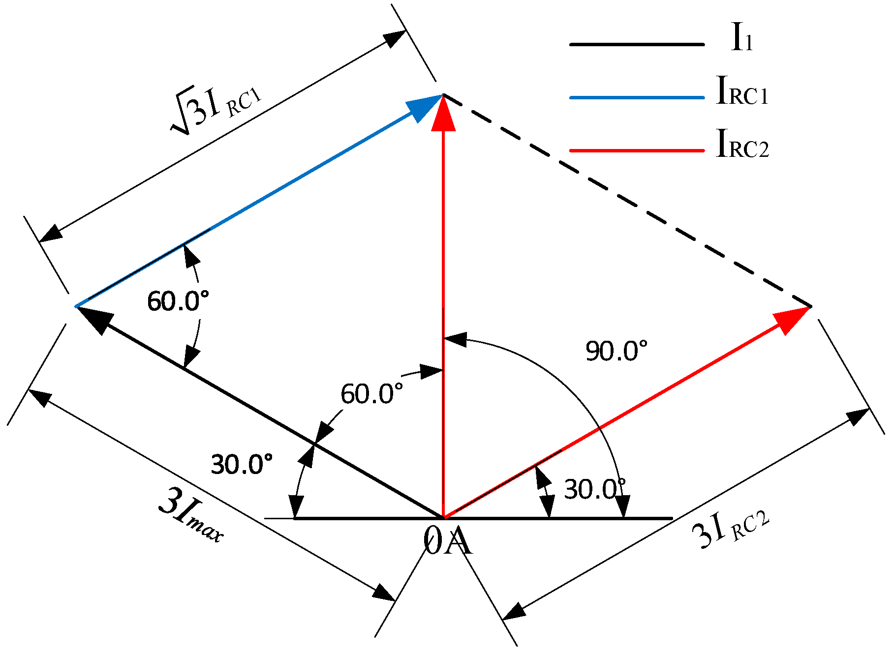
In order to make sure that the winding current works within the working area, as can be found in
Figure 5, the maximum value of winding current is in WP3 and WP4, which is described as
Imax, then the winding current will rise from 0A to
Imax, and back from
Imax to 0 A, as is shown in
Figure 6.
According to the parameters shown in
Figure 6,
The results show that with the well-calculated IRC2 and IRC1, the winding current can be limited within the working area.
3. Comparison of Asymmetric H-Bridges with Circulating Current Concept for A 6/4 SRM
A three-phase SRM is chosen as the device under test. The flux linkage-current diagram of this machine has been described in
Figure 5. The machine is a 6/4 SRM with 120 mm outer stator diameter and 80 mm stack length. Its rated voltage is 200 V, rated power 5 kW, rated torque 19.3 N·m and rated speed 1750 rpm. Both in the simulation and in the experimental setup, three current sensors are chosen for the feedback of the current signals, two of them measuring the leg currents
Ia and
Ic in the inverter legs, and the third one measuring the winding current
I1 in the ring structure, as described in (3). Three hall sensors are implemented for the position and speed signal, mechanically positioned at 0°, 120° and −120°, in a 6/4 SRM also resulting in electrical phase shifts of 0°, 120° and −120°.
As can be seen in
Figure 6, based on (6)–(8), the reference value for the circulating current can be well defined, the reference current for the leg currents in the inverter can also be defined by the reference speed [
16].
We compare the two types of control methods at a reference speed of 1000 rpm, and a load of 6 N·m. For the conventional method, the turn-on angle is 45 degree and the turn-off angle is 75 degree [
17].
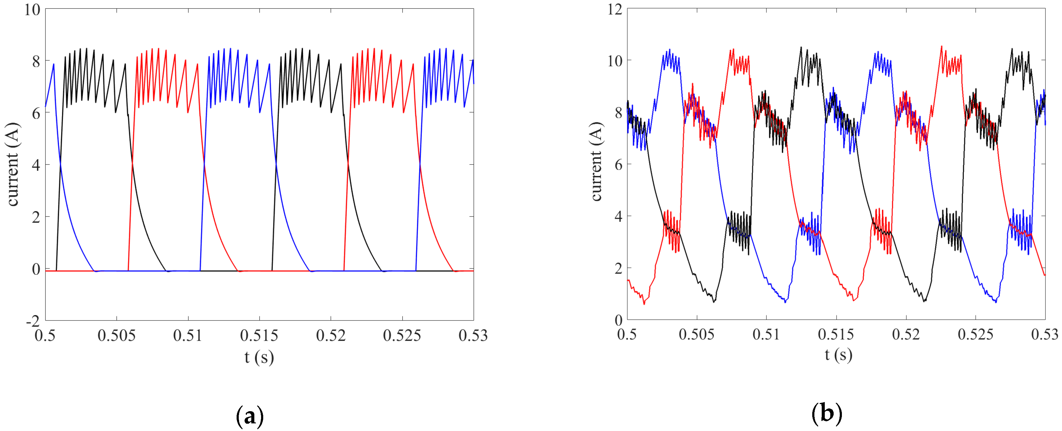
With the constant load of 6 N·m, and the reference speed of 1000 rpm,
Figure 7a describes the winding currents from the SRM driven by the conventional method, where we choose a turn-on angle of 45 degree and a turn-off angle of 75 degree (the optimization angles for driving three-phase SRM). It can be found that all excitation pulses are similar to flat top waves [
18], this is because with the fixed turn-on and turn-off degrees, the speed is controlled by the current hysteresis method.
At the same time,
Figure 7b shows the winding current waveforms from the SRM driven by the new method, where the excitation pulses of the new topology are more similar to trapezoidal waves. This is because the trapezoidal driving current is generated from the full bridge circuit, the function of the circulating current is only to increase the “zero level” of the winding current.
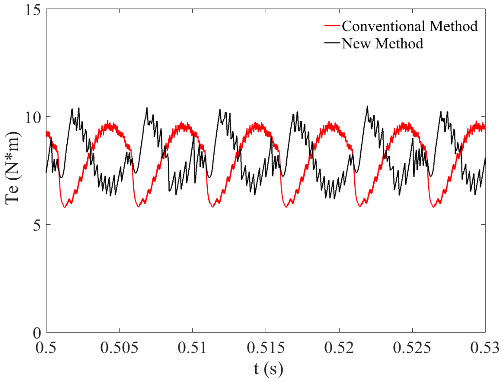
Figure 8 shows that for the different topologies, both of the peak-to-peak torque ripples are less than 5 N·m. This means that the new driving method can keep the torque performance of the conventionally driven SRM.
4. Current Studies
The waveforms of different currents at steady state can describe their different roles in the SRM [
19], which are all tested under the condition of 200 V DC voltage, reference speed of 1000 rpm and load of 6 N·m.
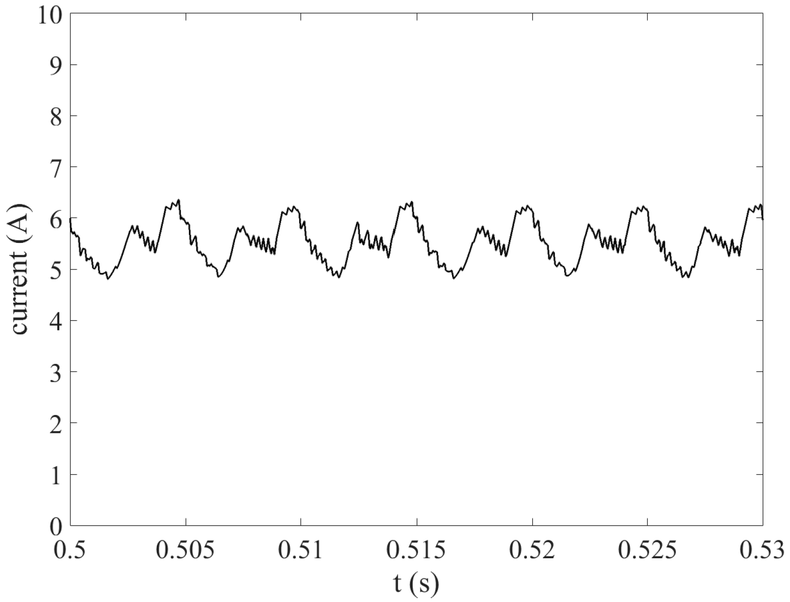
The waveform of the circulating current in steady state is shown in
Figure 9. Note that this current cannot be directly measured as such and it has to be calculated. Also note that it is not perfect DC. Because of the inductive energy storage in the windings and the delta structure, the circulating current contains a ripple of mainly triple harmonics, that repeats every 120°.
As is described in
Figure 3 and (1)–(3), the circulating current is the average current in the ring structure. From
Figure 9, with a reference value of 5.5 A, it can be found that the circulating current is kept relatively stable, which can generate the stable compensatory current for the winding currents.
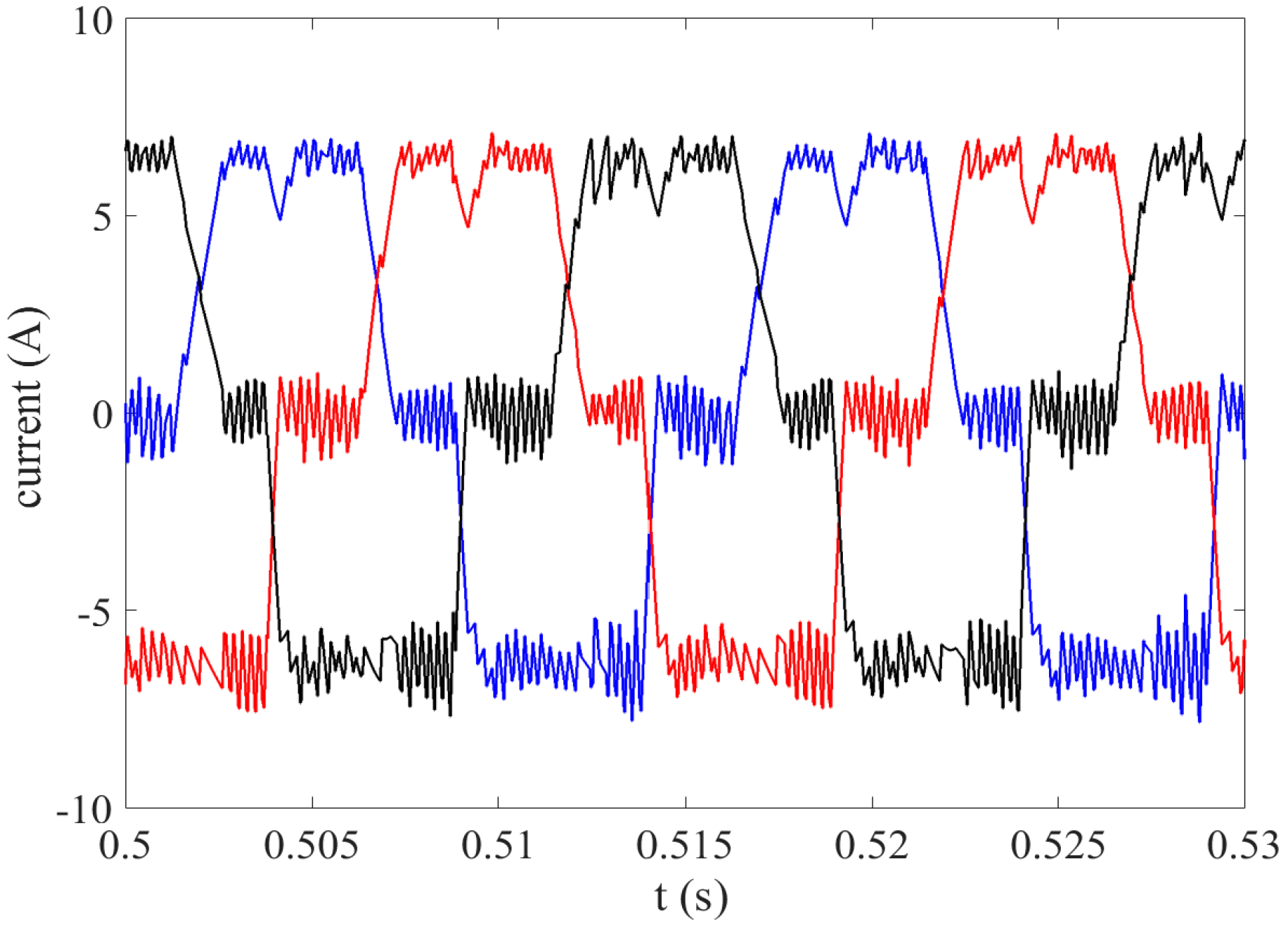
The curves of the current in each phase of the full bridge are shown in
Figure 10.
As can be found in
Figure 10, the leg current waveforms of the three-phase bridge have a trapezoidal shape but are not symmetrical, which is because the ring structure tries to guarantee the winding currents to be positive, while the inductances are changing, which cause asymmetry in the inverter currents.
From
Figure 10, combined with
Figure 7b and
Figure 9, it can be found that because of (5), the winding current is the vector sum of circulating current and leg current from the inverter. It is also worth noting that because of the triple harmonics in the circulating current, the waveforms of three-phase winding currents were not totally similar.
5. Influence of the Speed and the Load
By using the simulation tools, the characteristics of the SRM can be analyzed. The performance of the SRM is mainly manifested in its speed and torque characteristics [
20], and based on the operation principle described above, these characteristics are determined by the winding currents.
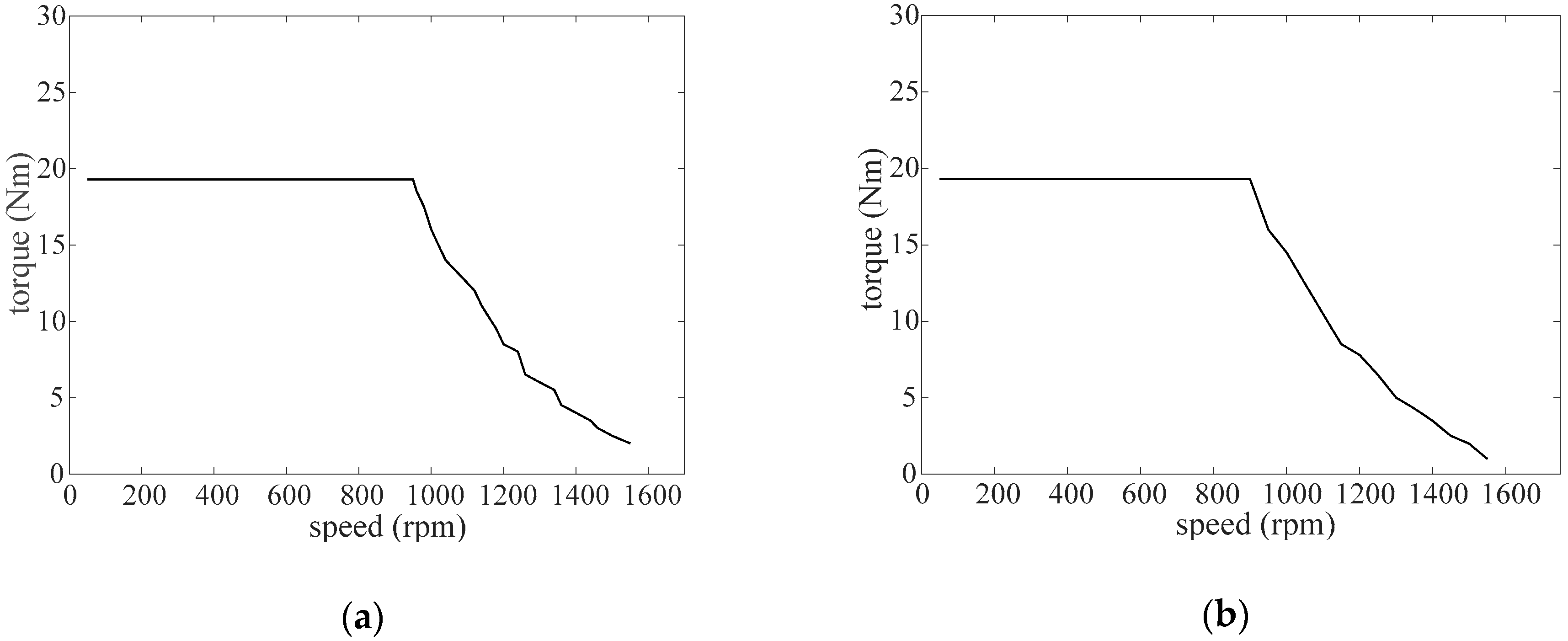
Figure 11 describes the relationship between the speed and torque of the SRM driven by the conventional method and new method.
As can be found in
Figure 11a,b, with the torque rating 19.3 N·m, the speed can range from 50 to 1000 rpm, because
where
P is the power of the SRM,
T is the torque of the SRM, and
N is the speed of the SRM.
With the constant torque of 19.3 N·m, from 50 to 1000 rpm, the SRM works in the constant torque area, because in this area, the power of the SRM does not achieve its highest value (power rating), the speed can increase with the constant load. The power of the SRM increases with the increasing speed, after the point of
N = 1000 rpm, the highest power is achieved, and then keeps constant with the increasing speed, as the result, the torque decreases [
21].
From the comparison between the two control methods, it can be found that for a specific SRM, its relationship between speed and torque does not change even driven by different methods, it also proves that the new method does not change the characteristics of the SRM.
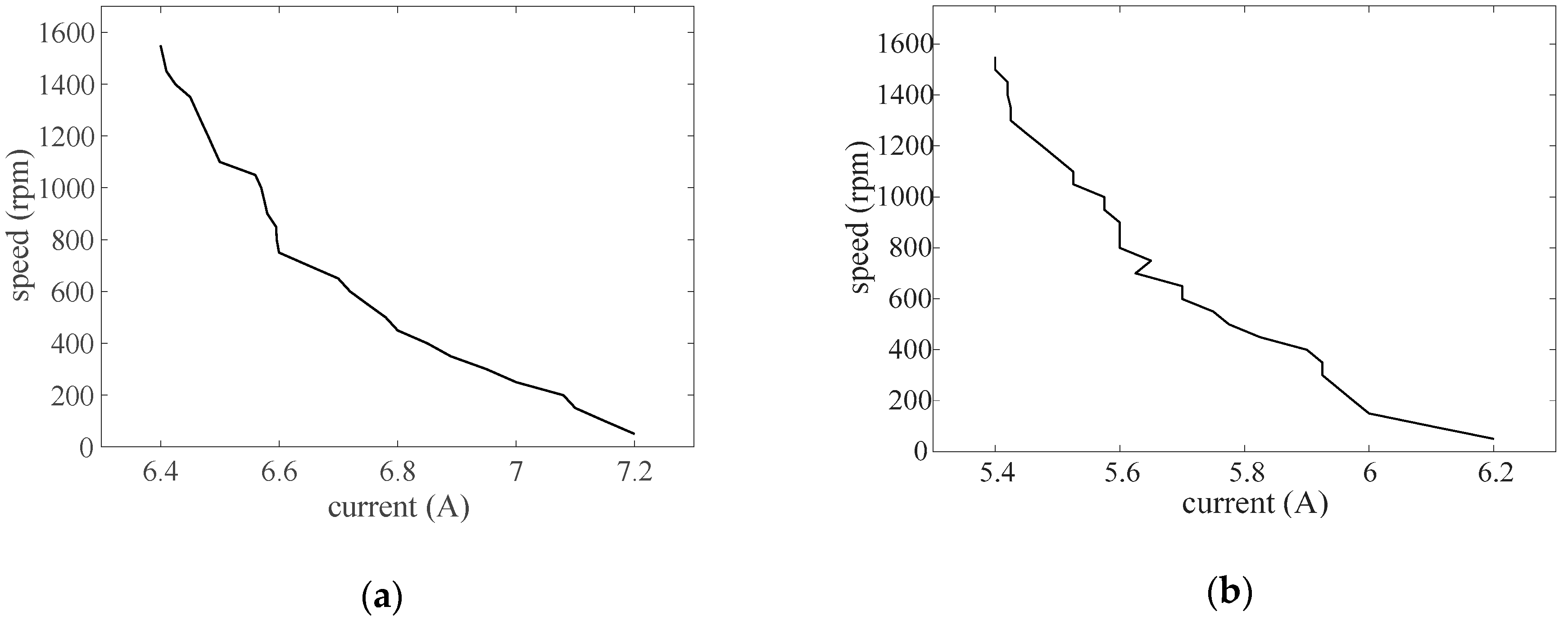
Figure 12 shows the relationship between the speed and winding current of the SRM driven by the conventional method and new method, with a constant load of 6 N·m.
From
Figure 12a,b, it can be found that the trends of the winding current based on increasing speed of both the two methods are similar: with a constant load, the winding current increases, and then the speed decreases. This is because with the decreasing winding current and constant excitation voltage, the back EMF in the armature decreases, which leads to the increase of armature current, and then the torque increases, as the result, the speed of the SRM increases [
22].
In fact, no phase lead has been implemented in this article. Actually, at the same time, in order to keep the higher speed, the frequency of the winding current will also increase [
23].
From
Figure 12 it can also be found that with the same speed, the value of the winding current in the new method is less than the one in the conventional method. This is because of the change of the on and off angles, the on-time of the winding in the new method increases, the amplitude of its current has to be decreased.
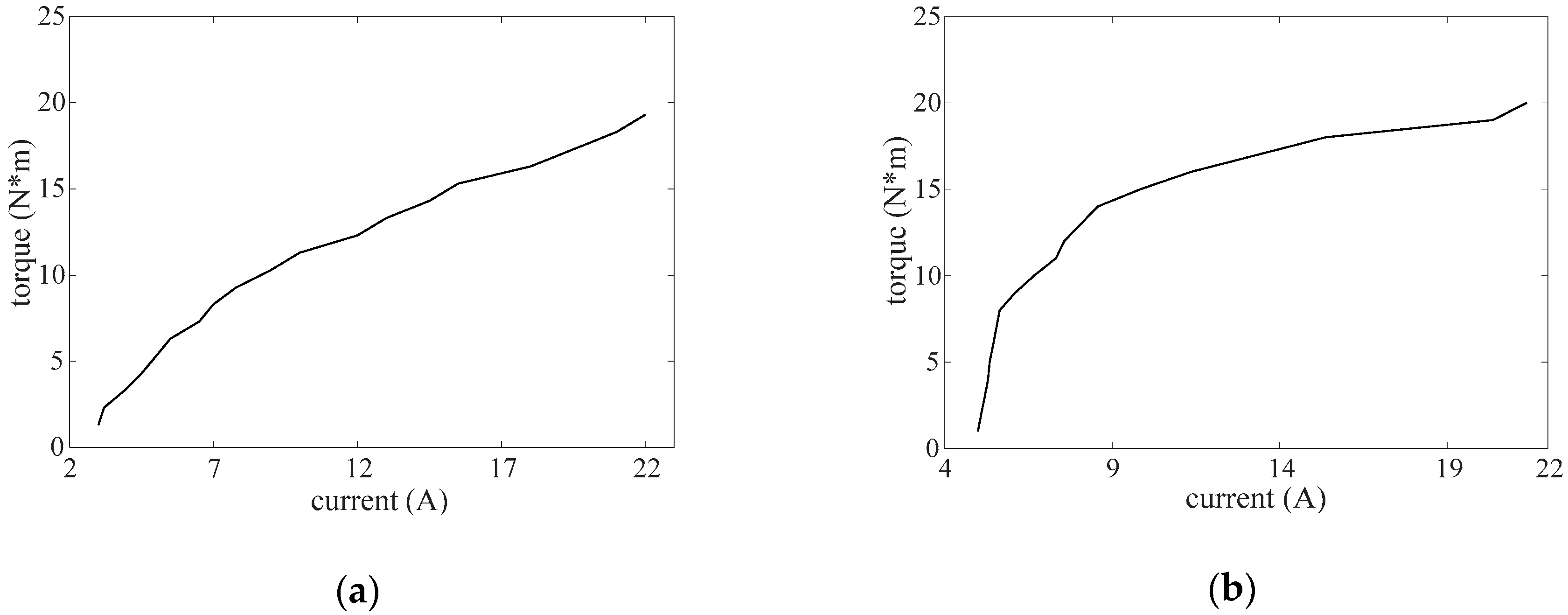
Figure 13 describes the relationship between the winding current and torque of the SRM driven by the conventional method and new method, with a constant reference speed of 1000 rpm.
The similar waveforms of the winding current based on increasing torque with different control methods are described in
Figure 13a,b, it can be found that with the constant speed, the winding current increases, then the torque increases as well. The reason is that with the increasing load, the output power of the SRM increases, if the excitation voltage keeps constant, the winding current will increase, as the result, the torque of the SRM also increases [
24].
It is also worth noting that with the same torque, the values of the winding current in the two control methods are different, of which the reason is the different topologies of the two driving circuits. In the winding of the SRM driven by the conventional method, only one phase winding is turned on at the same time (
Figure 7a), for the winding of the SRM driven by the new method, however, there are at least two phase windings turned on at the same time (
Figure 7b), and both of them can generate torque for the SRM.
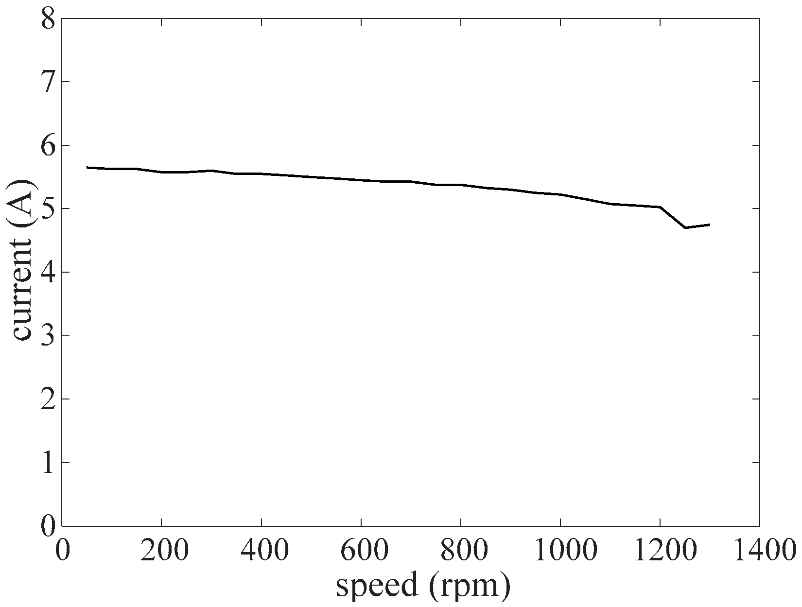
Figure 14 shows the relationship between the speed and the circulating current of the SRM driven by the new method, with a constant load of 6 N·m.
With a reference value of 5.5 A, it can be found from
Figure 14 that the circulating current keeps relatively constant even with the increasing speed. It is also worth noting that the SRM works in the constant power area when the speed achieves 1300 rpm with a load of 6 N·m. It also proves that for a specific SRM, the circulating current keeps relatively constant, which does not change with the speed or load.
By making the analysis among the winding current, circulating current, torque and speed of the SRM driven by the new method, it can be found that even with the new driving method, the SRM can keep its own mechanical properties, where the ring structure will not have a bad influence. For an SRM, it can be easy to make a prediction of its performance with the new driving method, based on the existed characteristics of the SRM.
6. Validation
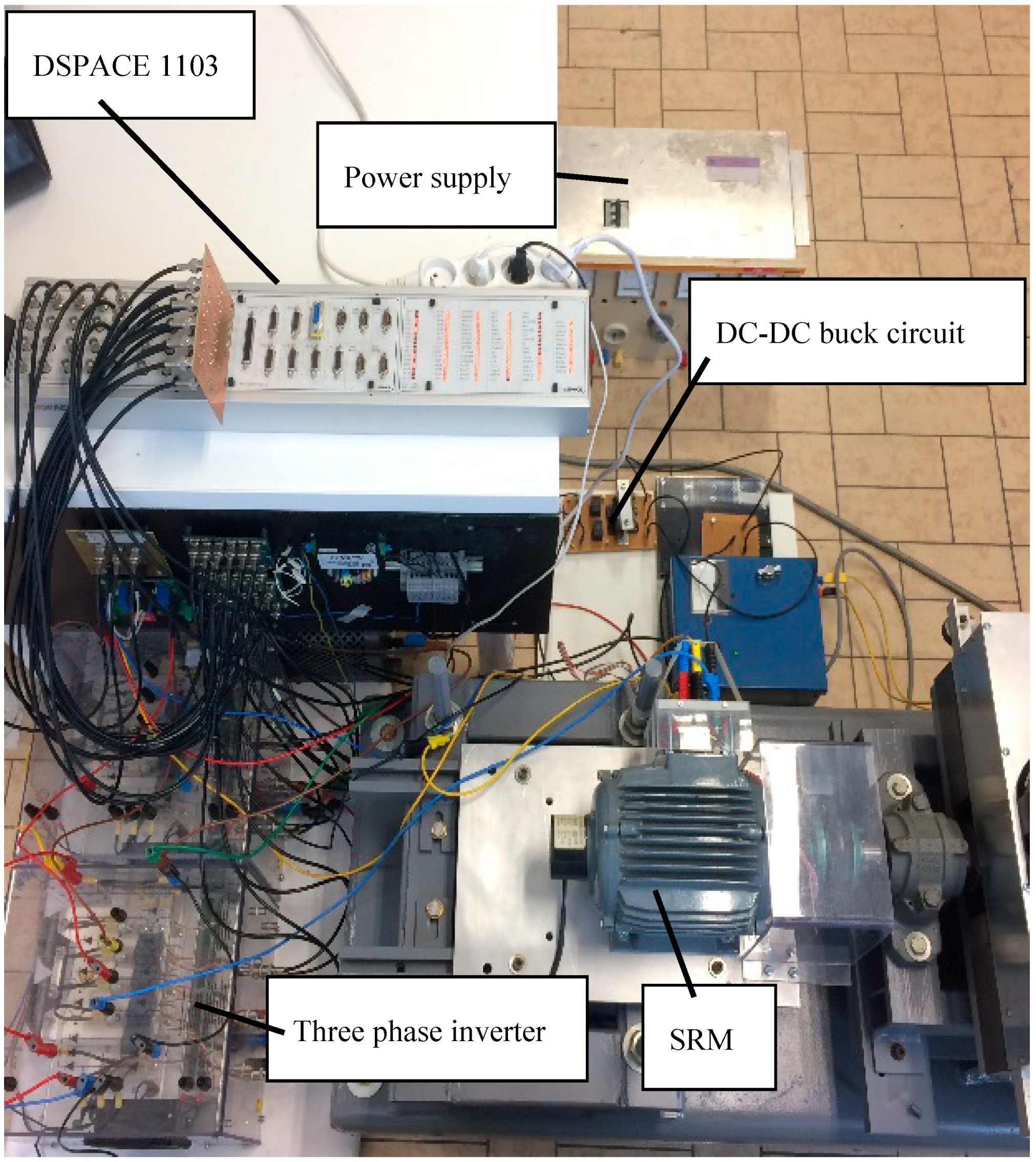
The experimental system consists of a switched reluctance motor with the characteristics described in
Section 3 and
Figure 5, a breaking machine with torque sensors, a conventional inverter box, current sensors, position sensors, a 200 V DC power supply, a DC-DC buck circuit, a DSPACE 1103 controller board, and the PC with DSPACE 1103 blocks installed. The experiment system is shown in
Figure 15.
The windings inside the SRM were connected in series. According to (3), there should be at least three current sensors in the experiment system, two of them are used to measure the leg currents in the three-phase inverter, the rest was used to measure the winding current. With the feedback of position signals and the current signals, the SRM could be controlled by regulating the current in the inverter [
25] and the current in the DC-DC buck circuit.
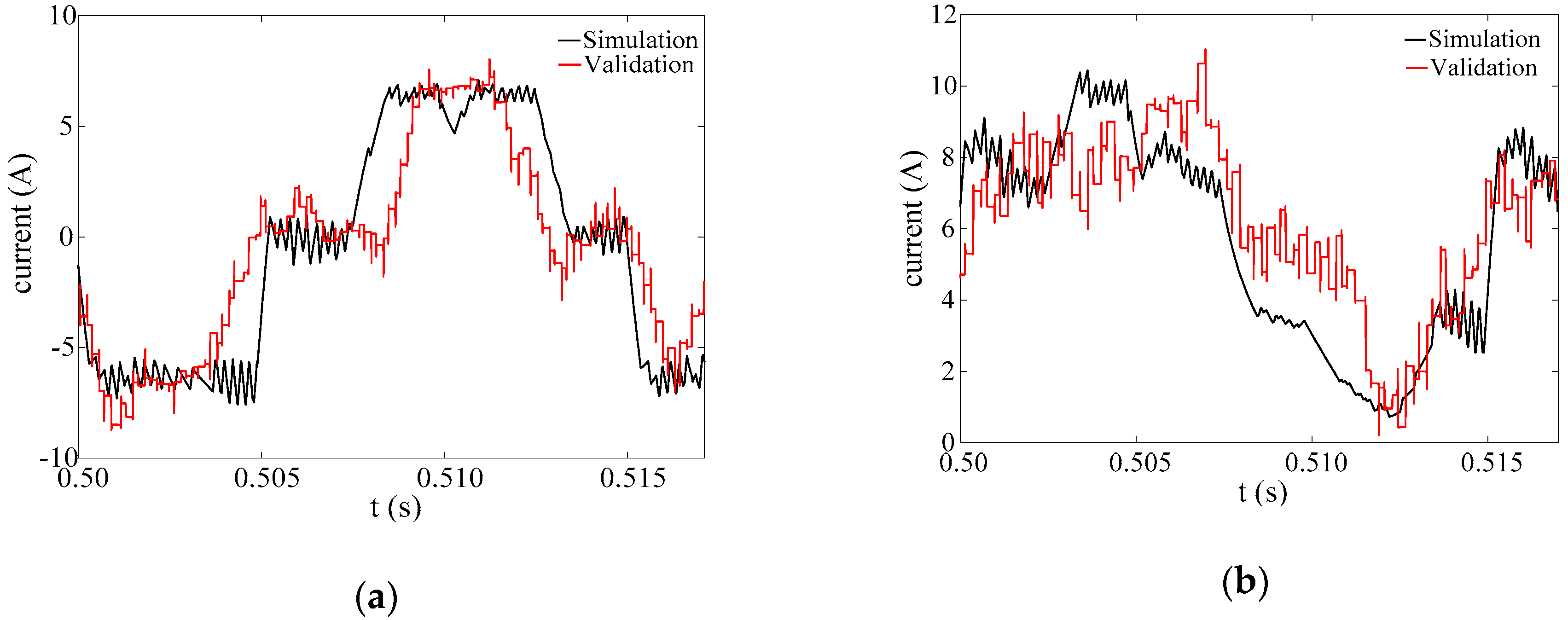
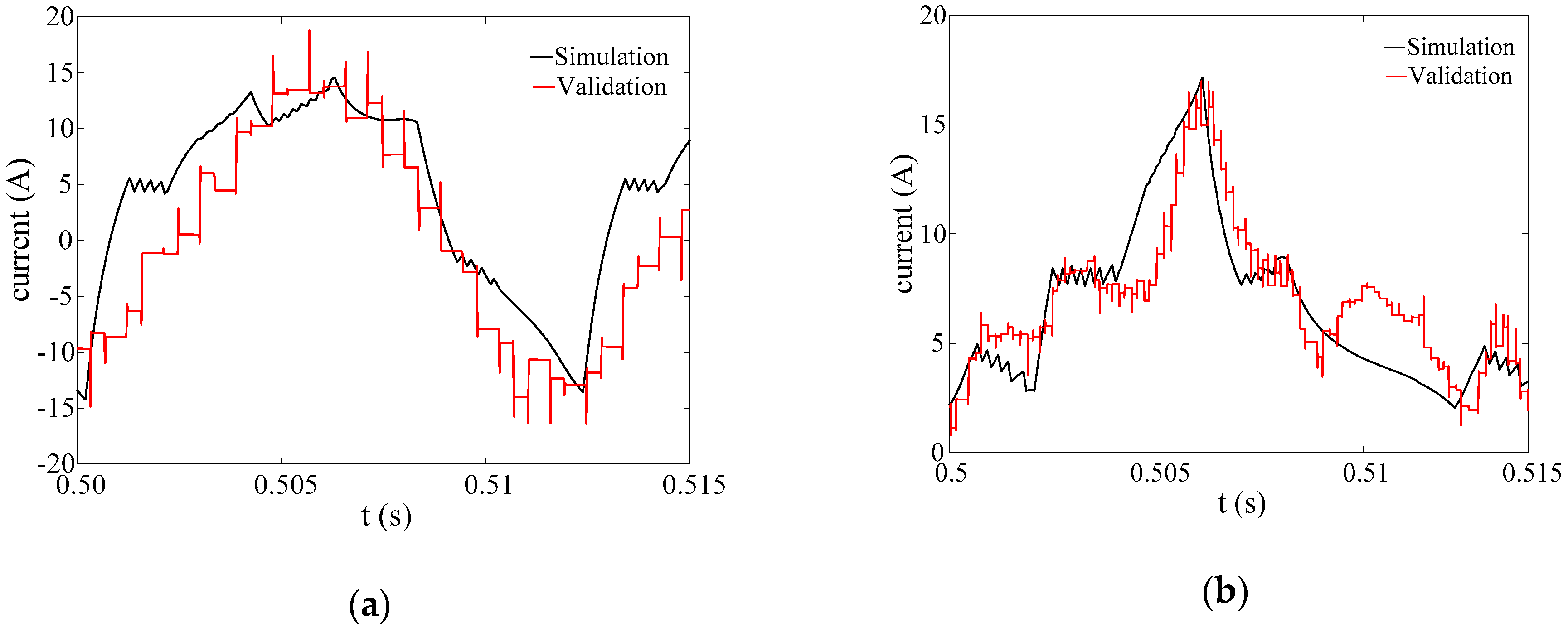
The reference speed of the SRM was set to 1000 rpm, and the load was set to 6 N·m. Both of the simulation results and experimental results of the leg current and winding current are shown in
Figure 16.
From the comparison between simulation and validation in
Figure 16, it can be found that for both of the leg current and the winding current, the measured results match well with the simulated ones.
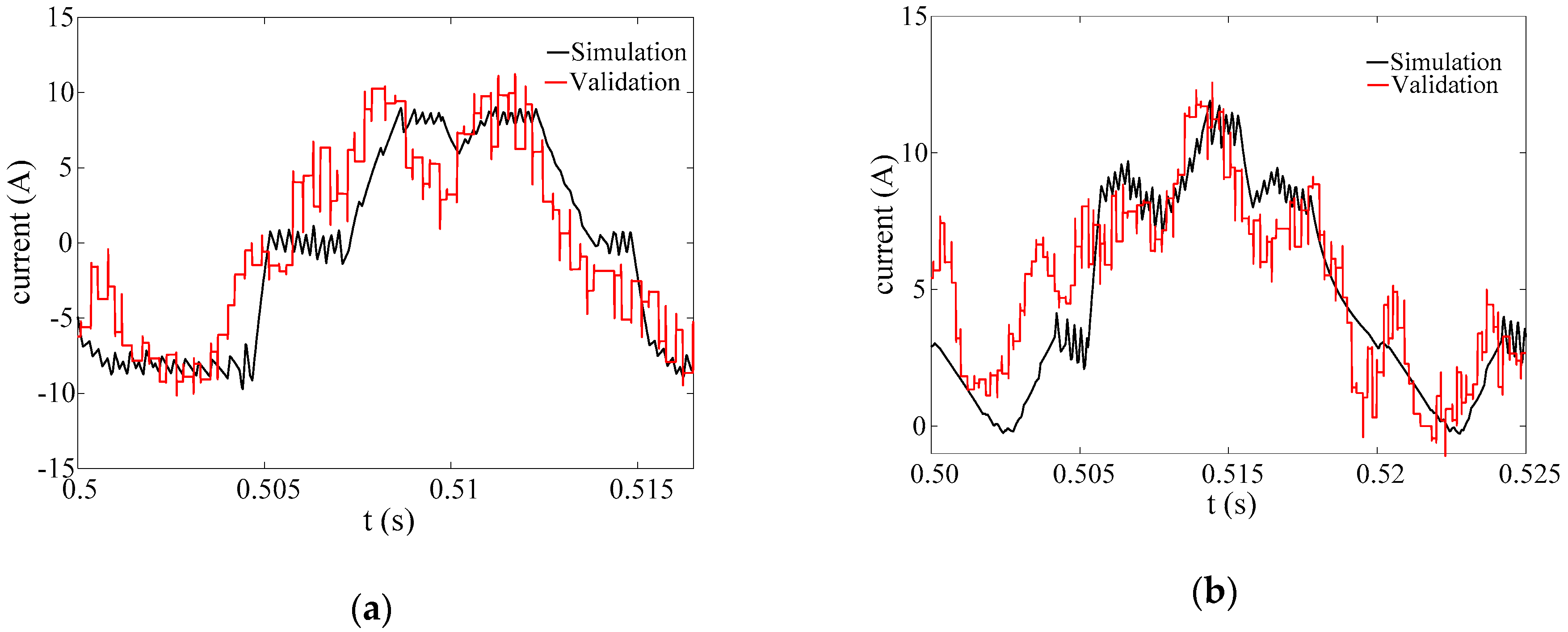
Figure 17 shows the simulation result and experimental result of the leg current and winding current, where the reference speed is increased to 1300 rpm, and the load is kept at 6 N·m.
Based on
Figure 11, with a load of 6 N·m and a speed of 1300 rpm, the SRM works in the constant power area, so in comparison with
Figure 16, from
Figure 17, a good agreement with the theoretical analysis can still be observed for both of the measured results and simulated results, which shows a higher frequency and slope limited current waveforms than in
Figure 16.
Figure 18 shows the simulation result and experimental result of the leg current and winding current, where the reference speed is kept with 1000 rpm, and the load is increased to 8 N·m.
Based on the analysis in
Section 5, with the increasing load, the amplitude of the excitation current will also increase. In comparison with
Figure 16, from
Figure 18, it can be found that both of the simulated results and measured results have the same trend with the theoretical prediction.
From
Figure 16,
Figure 17 and
Figure 18, it is also worth mentioning that the minor error between the results of simulation and validation, of which the influencing factors are electromagnetic noise from the cables and sensors, as well as the measuring error and accuracy, these contribute to the discrepancy and the ripple in the measured results.
The validation proves that the new control method can be applied in the practical system; the theoretical analysis and the parametric studies can be verified with the experiment, and the results of the validation show the same trend as the simulation results even with different speed and load.
7. Conclusions
A new type of control method for SRM has been proposed, instead of asymmetric H-bridges, a conventional three-phase bridge was used to drive the SRM by using a ring topology.
Based on the phase windings connected in a series, the theoretical analysis of the proposed topology was made. A vector operation between the inverter current and the winding current was made to obtain the formula, with which the reference value of the circulating current can be obtained, based on the parameters of the SRM.
With the simulation tool, the comparisons between different driving methods were also made, based on the analysis of winding currents and torque waveforms, as well as the waveforms of the winding current, the circulating current, and the inverter leg current, and it explained how the new method drove the SRM with the standard inverter and trapezoidal currents.
The validation was also made to be compared with the simulation results. All the practical results showed similar trends with the simulation results with different speeds and loads (
Figure 16,
Figure 17 and
Figure 18).
As the result, the new topology for driving an SRM can be applied for an off-the-shelf SRM. It proves that it is possible to drive an SRM by using a standard full-bridge inverter and an additional DC-source. By controlling the inverter currents and adding a circulating current, an SRM can also be controlled with waveforms that can be used for driving a BLDC but not limited to these. At the same time, the new topology also has the versatility for different type of SRMs.

 ,
, 


