
Coordinated Operation and Control of Combined Electricity and Natural Gas Systems with Thermal Storage


1
School of Electrical Engineering, Southeast University, Nanjing 210018, China
2
State Grid Jiangsu Electric Power Company Research Institute, Nanjing 211103, China
*
Author to whom correspondence should be addressed.
Energies 2017, 10(7), 917; https://doi.org/10.3390/en10070917
Submission received: 5 April 2017
/
Revised: 13 May 2017
/
Accepted: 29 June 2017
/
Published: 3 July 2017
(This article belongs to the Section F: Electrical Engineering)
Abstract
:As one of the most effective approaches in dealing with the energy crisis, combined electricity and natural gas systems have become more and more popular worldwide. To take full advantages of such hybrid energy networks, a proper operation and control method is required. In this paper, a novel approach coordinating combined heating and power generation is proposed. First, state excursion rate, a criterion describing the deviation of system operation, is defined for system state evaluation. Then, thermal energy storage is allocated to provide more and better operation modes for combined generation. By investigating the state excursion rate of hybrid energy systems, the optimal operation mode is chosen through an analytical strategy. Case studies on hybrid energy networks show that all state variables, including voltages in electric systems and pressures in gas networks, are adjusted to follow proper operation constraints by the implementations of the proposed strategy. In addition to providing sufficient auxiliary services for hybrid systems, it is also possible to maintain the economic and energy-efficient benefits of energy supply. This study provides an effective method to utilize the regulation capability of combined heating and power generations, which is a technical basis of energy internet.
1. Introduction
Energy internet, which is envisioned to be the architecture of future automated and flexible electric power distribution systems, has drawn wide attention in both academic and industrial fields [1]. With the integration of multiple energy sources, the upcoming energy internet will evolve to be a hybrid energy system with diverse generation sources, transmission media, and consumption terminals, leading to the interconnection of electric power networks, natural gas networks, and traffic road networks. This kind of integration can effectively improve energy use efficiency from the perspective of total energy consumption, which is a potential approach dealing with the global energy crisis [2].
Based on this background, studies focusing on the design and operation of hybrid energy systems have emerged worldwide. Destro et al. presented an optimal design and management strategy for the tri-generation system composed by a photovoltaic plant, a diesel CHP engine, a reversible heat pump and a boiler in [3], where various energy types, including power, heating, cooling and water, are considered. One typical hybrid energy unit, the distributed energy system in a hotel, is investigated by Zhou et al. in [4], and an effective planning approach based on a two-stage stochastic programming model is proposed to manage the allocation of diverse devices. Considering the micro combined heating and power generators (micro-CHP) rated between 1 kW and 5 kW, Kopanos et al. [5] established a linear mixed integer programming framework to coordinate the operations of multiple micro-CHPs and optimize the interchanges of heating within subgroups of the micro-grids. Beside academic research, the hybrid energy systems have also been projected and constructed in actual industrial applications. Borelli et al. reported that the Genoa demonstrator, consisting of a turbo expander and an internal combustion combined heat and power unit, is able to recover wasted mechanical energy and serve heating and power demand [6]. This study is a part of the European Combined Efficient Large Scale Integrated Urban Systems (CELSIUS) project, which aims at supporting any European city to maximize the utilization of its primary and secondary energy resources. The idea of using renewable energy to drive combined generation systems is proposed by Ju et al. and verified in Guangzhou Higher Education Mega Center (GHEMC) [7]. The results show that such implementation will enhance performance of combined generation systems remarkably. Falke et al. [8] proposed a multi-objective optimization and simulation model considering various distributed heat and power generation units, storage systems, energy-saving renovation measures, and district heating networks. The developed model is applied to a residential district in Lampertheim, a town in Hesse, Germany, and demonstrated to be effective for real hybrid energy system modeling.
As reviewed above, hybrid energy systems with different energy forms and diverse driving devices have been explored. Considering the fast development of distributed natural gas networks, distributed gas turbines (GT) have been highlighted as a satisfying energy hub in recent years, which is able to convert energy from different systems, i.e., electric power networks and natural gas networks, to energy consumers. Aiming at different types of energy demand, GT-based energy hubs can evolve to be a combined heating and power (CHP) generation system or a combined cooling, heating and power (CCHP) generation system via installation of ancillary devices [9]. From practical applications in China, cooling load demands in summer are supplied by air-conditioning systems, which are commonly electricity driven. Heating load demands are mostly supplied by central heating systems, so CHP systems are more widespread in utility facilities and attract more research attention in the industry [10]. By making use of waste heat released from turbines for thermal supply, CHP systems help improve overall energy efficiency of generators from 30% to almost 80% [11]. Beside the remarkable enhancement of energy efficiency, the connection of electricity networks and natural gas systems provides mutual support for both energies, significantly improving the reliability of total energy supply. Hence, there has been a strong push globally for the CHP system and consequently it is often prioritized from an urban planning perspective [12].
Though with higher efficiency and reliability, CHP systems still face many challenges, of which determining the optimal operation mode is considered to be most fundamental. Following the electric load (FEL) and following the thermal load (FTL) are currently the most common strategies in the industry worldwide. Jalazadeh-Azar has compared the thermodynamic performance of FEL- and FTL-based CHP system operations, whose results demonstrated that a CHP system with FTL operation mode is superior from the first-law thermodynamic standpoint [13]. Three criteria, i.e., primary energy consumption (PEC), operation cost and carbon dioxide emissions (CDE), were introduced by Mago et al. [11] to evaluate the performance of CHP systems operations under different strategies and climates. The results show that FEL-based CHP systems always increase the PEC, while FTL-based CHP systems achieve reductions of PEC, CDE, as well as operation cost. In addition to simple FEL and FTL operations, some smart strategies of CHP systems are also discussed in the literature. Fang et al. proposed an optimal operational strategy based on an integrated performance criterion (IPC), which achieved an effective switch between FEL operating mode and FTL operating mode while taking PEC, CDE, and operation cost into consideration [14]. Considering the integration of photovoltaic (PV) power, Brahman and Jadid allocated both electrical energy storage (EES) and thermal energy storage (TES) in a cogeneration system to mitigate the impact of mismatch between electricity demand and thermal demand, achieving both energy cost and CDE reductions [15]. A nonlinear model called TOOCS-off, which is a shortened form of techno-economic optimal operation of cogeneration systems—off, was developed by Reza in [16] to control the electrical energy flow and the thermal energy flow on the load side, showing the optimal energy management of CHP energy systems. Cascio et al. proposed a multi-objective optimization model for urban integrated electrical, thermal and gas grids, which achieves an operational cost reduction of about 17% with the respect to thermal-load-tracking control logic [17]. Targeting the maximization of owners’ profits, a discrete operation optimization model for CHPs in real-time markets is proposed by Gu et al. in [18], and the potential operating strategy is pre-developed based on the forecasted prices and modified by dynamic modification process. An operation strategy following a hybrid electric-thermal load (FHL) is proposed by Li et al. in [19] to manage hybrid energy systems to achieve overall benefits of primary energy saving, exergy efficiency enhancement and CDE reduction.
However, current researches on operation strategies of CHP systems are all from the customer’s perspective. That is to say, the analyses are based on local sites of residence or commerce. Even new indices, such as source primary energy consumption, is just a conversion between source and site for equivalent energy performance evaluation [20]. The interactions between CHP units and hybrid energy networks are commonly ignored, while the impact may be remarkable and cause severe problems for grid operators. For example, although FTL operation mode of CHP system is proved to have more economic benefits and higher energy efficiency [11,13], such operation strategy makes CHP system a random generation source or uncertain electric load from the view of electric power network, leading to remarkable uncertainties in electricity networks. This kind of stochastic feature may cause severe risks in electric distribution networks, especially considering the integration of distributed generations (DG). On the other hand, gas turbine-based generation systems are expected to interact with the electric power grid to provide auxiliary services, such as spinning reserve, peak shaving, and demand response, and then to improve the capability of renewable resource penetration [21]. Therefore, a desired operation strategy of CHP system should provide regulation services for network operation instead of uncontrollable effects. The same requirements exist in natural gas networks. Additionally, the inconsistent features of hybrid energies from diverse transmission systems should also be handled. Generally, gas networks are not as flexible and responsive as power networks, indicating much more restraints in operation. To realize the unified state evaluation of combined electricity and natural gas networks, Geidl and Andersson have presented an optimal power flow approach to deal with coupled power flows of hybrid energy systems in [22], which is verified in a 3 electric nodes and 3 natural gas nodes coupled system. However, the computational difficulties might be expected for realistically sized problems as stated by the authors.
In the framework of energy internet, the operating states of hybrid energy networks, both electricity systems and natural gas systems, should be simultaneously considered and controlled while formulating the optimal coordination of the hybrid energy systems. To the best of the authors’ knowledge, the system states of hybrid energy networks are treated as constraints in the existing studies. As a further step, it is desired to involve the CHP systems in hybrid system control, i.e., utilizing the CHP unit to address the network abnormality. Hence, the coordination of the hybrid energy systems should consider the benefits of both grid operators and CHP owners other than only one aspect, which is rarely researched in the reviewed literature. With these concerns, a proper operation strategy should take the following requests into consideration. Firstly, the sufficient economic and energy benefits should be maintained. Then the negative impact of CHP unit on the connected networks, including electricity systems and natural gas systems, should be mitigated. Lastly, the regulation capability of CHP unit should be utilized to guarantee that both electricity networks and natural gas systems are in normal conditions, like the utilization of auxiliary services for power systems. This is a progressive guideline on the optimal control of hybrid energy systems, which is also the technical basis of energy internet construction and application.
In this paper, a novel operation and control strategy of combined heating and power systems is proposed. The operation states of hybrid energy systems, including both electric power networks and natural gas networks, are considered as new criteria, which are indexed by state excursion rate (SER). By analyzing SERs of electricity systems and gas systems, the optimal operation mode of CHP generation is shifted based on modified FEL and FTL strategies. In order to achieve flexible and sufficient controls with the proposed method, the thermal energy storage is allocated in CHP systems. By implementations of the proposed control method, the CHP systems not only operate in an economic and energy-efficient way, but also contribute to network regulations of both energy systems. The operation of hybrid energy networks is improved greatly.
The remainder of this paper is organized as follows: Section 2 elaborates on the modelling of hybrid energy systems with CHP generation as an energy hub. The criterion and strategy of the proposed operation and control method are presented in Section 3. Section 4 describes the case studies and discussions. Conclusions are drawn in Section 5.
2. Modeling of CHP Based Hybrid Energy Systems
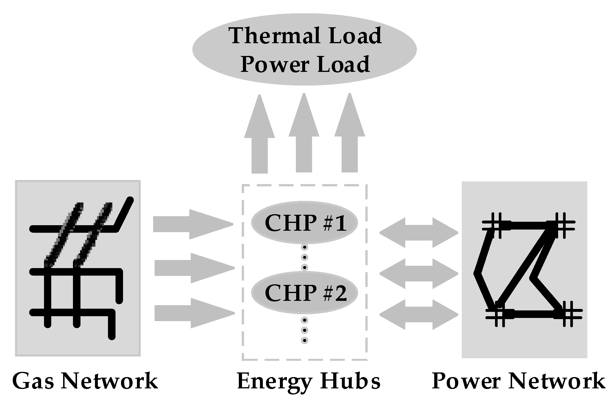
With combined heating and power generation as the energy hub, the typical framework of hybrid electricity and natural gas systems is shown in Figure 1. As can be seen, the whole energy internet can be divided into three parts based on the physical connections: power networks, gas networks and energy hubs. Power networks are connected with natural gas networks through CHP systems.
2.1. Natural Gas Network Formulation
In hybrid energy systems, the modelling of natural gas systems is simplified for specific research purpose. Generally, the primary elements considered in a gas network are pipelines, compressors, sources, and loads [23]. Like the nodal voltage in electric power systems, nodal pressure is the main state variable to determine energy flow in gas networks.
2.1.1. Pipelines
For pipeline k from node i to j, the flow rate (in standard SCF/h) can be expressed as [24]:
where Mk is a constant parameter related to internal diameter, length and friction of pipeline as well as temperature and compressibility factor of gas, and πi is the pressure at node i, and Sij reflects the gas flow direction of the kth pipe.
2.1.2. Compressors
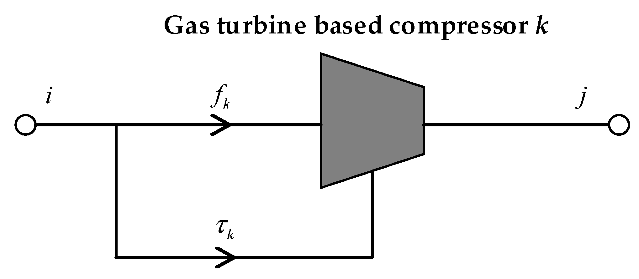
Compressors are installed in natural gas networks to transport gas and compensate for the loss of energy and pressure. Compressors require a significant amount of energy, such as natural gas, steam or electricity, to operate. Since natural gas-driven compressors show remarkable economic benefits in gas network operations, they are widely used. The structure of this type of compressor is shown in Figure 2.
Given a specific gas turbine based compressor, the actual adiabatic compressor horsepower follows the calculation [25]:
where Hk is the horsepower required to operate compressor k, fk is the gas flow rate through compressor k, Bk is a constant parameter determined by temperature and efficiency of the compressor, and Zk is a constant parameter related to compressibility factor. Based on (3), the gas consumption by compressor k can be approximated as:
where αc,k, βc,k, and γc,k are parameters of energy conversion efficiency of kth compressor.
2.1.3. Gas Energy Balance in Gas Networks
The mass-flow balance equation at each node can be written as:
where wi is the gas injection at node i, pk stands for the indices of pipelines connected to ith node and ck denotes the indices of compressors connected to ith node. Ai,pk, Ui,ck, and Ti,ck are parameters with following definitions:
2.2. CHP System Formulation
As seen in Figure 1, CHP system is the energy hub connecting energy sources and customers. It draws natural gas from gas networks, exchanges electricity with power networks and provides heating and power for energy users.
2.2.1. Modeling of GT Based Generators
According to the heat rate curve, the relationship between natural gas flow and power output based on gas fired turbines’ generators is as follows [23]:
where HRk is the input heating value of kth GT based generator, Pg,k is the output electric power by kth generator, αg,k, βg,k, and γg,k are coefficients decided by heat consumption curve of kth generator, wcon,k is the equivalent gas consumption by kth generator, and GHV is the gross heating value.
Along with electric power, thermal energy is also produced at the output of GT based generators. Power to heat ratio is the criterion calculating the proportion of generated electrical energy to the useful heating energy, which is defined as [26]:
where C is the power to heat ratio of the CHP unit, ECHP is the electric energy produced by CHP unit in a certain period of time, HCHP is the useful heat produced in the same period of ECHP, Finput is the fuel energy used by CHP system, ηe and ηh are the efficiency of cogeneration unit for producing electric power and heating energy, respectively, and η is the total energy efficiency of the CHP system following η ≤ 1.
According to reports provided by U.S. Department of Energy [27], CHP systems with low power to heat ratio, typically C ≤ 0.75, are currently cost effective in many markets and applications. In China, the typical technical parameters of representative gas turbine based CHP systems are shown in Table 1 [28], whose power to heat ratios are all below 0.75.
2.2.2. Loading Curves
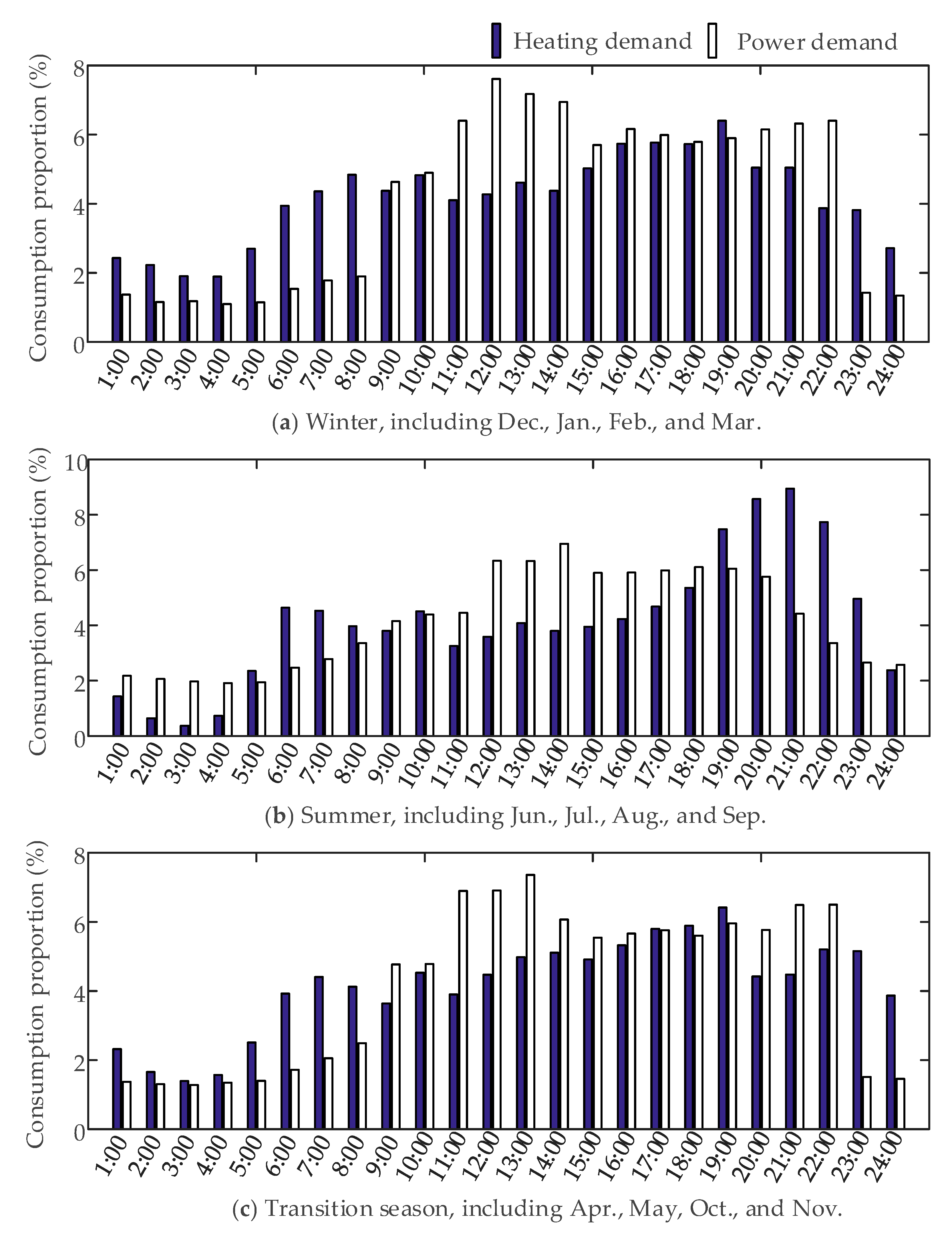
Combined heating and power systems are commonly allocated for energy supply of both electric and thermal loads. Based on design principles of CHP generation systems for the East Asia region [29], a typical 24 h loading data for a hotel powered by a CHP system can be concluded as Figure 3. The consumption proportion in the y-axis stands for the proportion of hourly energy consumption to the daily amount.
2.2.3. Thermal Energy Storage
CHP systems combined with thermal energy storage have shown remarkable benefits for various commercial building types [30]. It is a trend to install TES in CHP generation systems, and therefore the operation of cogeneration systems is affected. Details of these impacts are further discussed and utilized in Section 3.2.
From the view of system operation, the thermal storage operation can be formulated as:
where STES(t) is the total thermal amount stored in TES at t moment, and PTES(t) is the thermal storing (positive value) or releasing (negative value) rate of TES at t moment.
Obviously, based on the physical restraints of energy storage devices, following constraints should be considered.
where STES,max is the capacity of the thermal storage, and PTES,maxc and PTES,maxd are the maximal thermal storing and releasing rate of devices, respectively.
2.3. Unified Gas and Power Flow Analysis
The power flow in electric power networks can be expressed as:
where ∆Pi and ∆Qi are respectively the active and reactive power unbalance at node i, Pgen,i and Qgen,i are respectively the active and reactive power generation at node i, Pload,i and Qload,i are respectively the active and reactive load at node i, Vi is the voltage magnitude at node i, j stands for the indices of all nodes connected to ith node, Gij and Bij are respectively the real and imaginary part of the elements in the node admittance matrix, and θij is the phase difference between node i and node j.
Since the natural gas networks and electric power networks are connected through CHP systems, the whole energy conservation equations for unified gas and power flow analysis are listed as follows:
where wi,CHP(t) is the gas consumption rate by CHP system at ith node at time t, Pg,e(t) and Pg,h(t) are respectively the electric power and heating energy generated by CHP system at time t, Pl,e(t) and Pl,h(t) are the electric and heating load demand in CHP system at time t, respectively, and PEPN(t) is the power that CHP system exchanges with electric power networks. If PEPN(t) > 0, CHP system is an equivalent generator in power networks; if PEPN(t) < 0, CHP system is an equivalent load.
3. Criterion and Control Strategy of CHP Generations
From (19) to (24), it is observed that the operation mode of CHP systems has influences on system states of both gas networks and power networks. Though current control strategies of CHP systems are majorly focused on the cogeneration systems themselves, the interactions with connected grids should be seriously considered. Therefore, how to evaluate this impact is required at the first place, and then mitigation of these undesired impacts on the system operation is needed.
3.1. State Excursion Rate
System states would vary from time to time due to the change of loads, distributed generations, as well as CHP system operations. In order to give a proper and simplified evaluation of abnormal system states, the state excursion rate (SER) is defined as:
where x stands for the system state variable, such as nodal voltage in power system or nodal pressure in gas networks, and xmax and xmin are the upper and lower bounds of state variable, which are stipulated by local utilities or industrial standards.
Obviously, SER is an index representing the degree of system running out of normal operation. Because SER is capable of describing both electric power networks and natural gas systems, it is adopted in this paper for system state evaluation.
Considering the multiple uncertainty sources in networks, the system state would deviate to some extent even under regular operations. Based on SER given above, three constraints are defined to ensure both gas and power system operations are within proper states.
where (26) describes the permissible maximum bias of each state variable, (27) represents the allowable average bias of all interested state variables, and (28) is a constraint from the time domain, indicating the maximal duration of specific bias should be limited. σ1, σ2, σ3, and t1 are respectively the threshold values. xi denotes the ith state variable, and x is the state variable vector.
3.2. Optimal Control of CHP Generation
Considering the installation of thermal energy storage, the CHP system operation modes are modified and extended based on conventional FEL and FTL modes.
- Following the electric load with thermal energy storage absorbing heat (FEL-TESA).CHP generation follows the electric demand of the load. The thermal energy produced is more than required, and the excess energy is stored in the thermal storage devices.
- Following the electric load with thermal energy storage releasing heat (FEL-TESR).CHP generation follows the electric demand. The thermal energy produced cannot meet the heating requirement of load, and the lacking part is supplemented by thermal storage.
- Following the electric load without thermal energy storage operation (FEL-TESO).CHP system follows the electric demand, while the thermal generation exactly matches the heating requirement. Thermal energy storage devices are out of working at the moment. This mode is activated only when the power to heat ratio of CHP system equals to the ratio of electric demand to heating requirement.
- Following the thermal load without thermal energy storage operation (FTL-TESO).CHP generation follows the thermal demand of load and the thermal storage devices are out of working. The mismatch part of produced electricity, no matter redundant or insufficient, is handled by power networks.
- Following the thermal load with thermal energy storage absorbing heat (FTL-TESA).In order to make CHP system provide more generations, thermal storage operates at heat storing mode. Therefore, the total heating requirement becomes the summation of regular heating load and thermal storage. CHP generation follows the updated thermal demands.
- Following the thermal load with thermal energy storage releasing heat (FTL-TESR).In order to make CHP system produce less generations, thermal storage operates at heat releasing mode. Therefore, the heating requirement of load is partly supplied by thermal storage, and the request for thermal generation of CHP system is alleviated. CHP generation follows the lessened thermal demands.
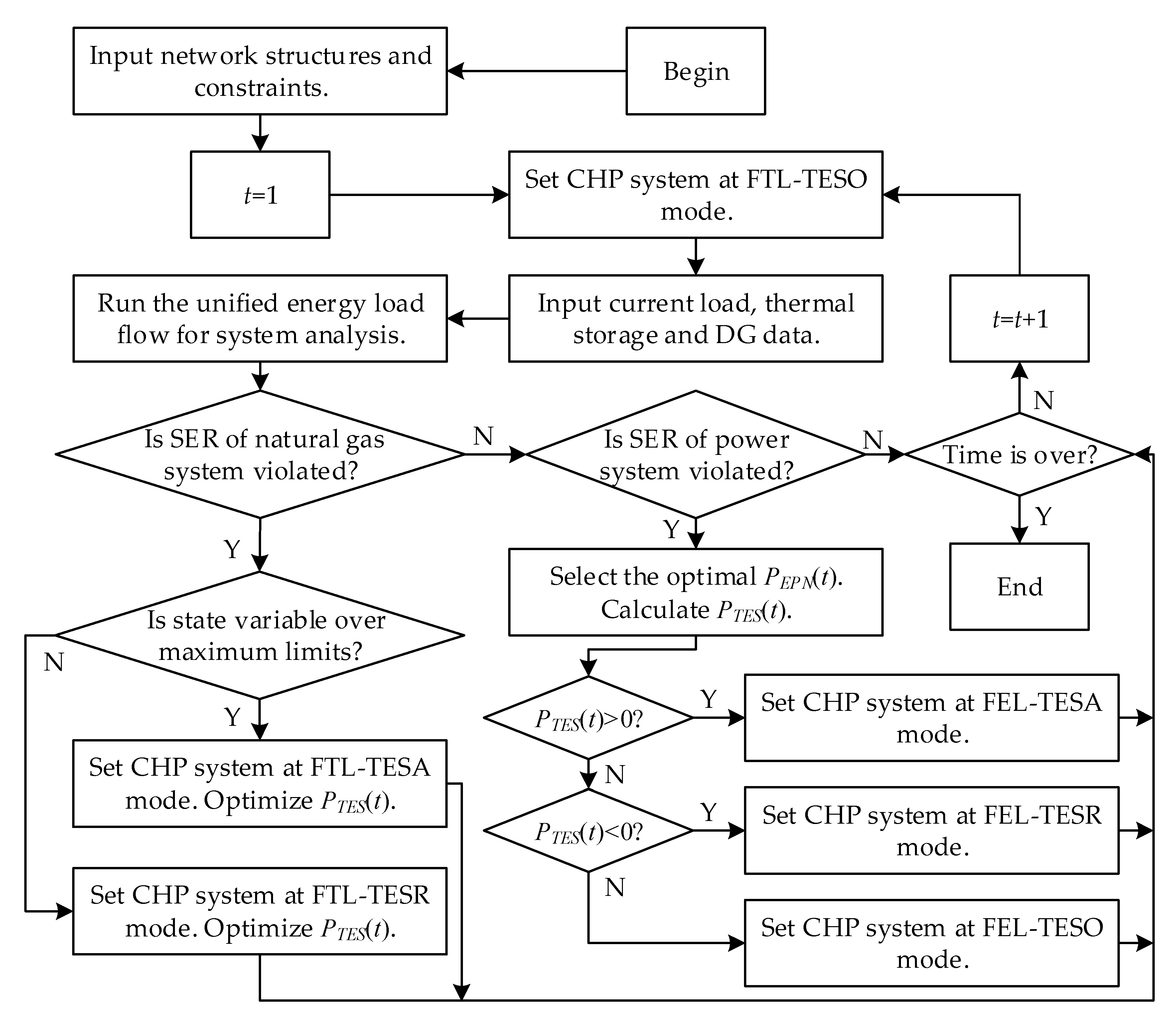
A proper operation strategy of a CHP system should avoid the network running out of the constraints caused by either cogeneration itself or other factors such as distributed energy integrations. By implementing the proposed operation modes, the integrated energy system is able to operate at an economic and energy-efficient way, in addition to providing the auxiliary services in hybrid energy networks. The operation strategy of controlling CHP systems is shown in Figure 4, where CHP generation is shifted between the presented modes.
3.3. Coordination Control of Multiple CHP Systems
The proposed strategy shown in Figure 4 is directly adequate for operation control of hybrid energy systems with single CHP coupling. When it comes to the multiple CHP generations integrated in the hybrid energy systems, the proposed approach is still feasible to every individual CHP system, but the coordination between diverse CHP units are required. In order to address this concern, an optimization-based strategy coordinating multiple CHP units is proposed with the objective set as:
where NCHP is the total number of CHP generations coupling hybrid energy systems, and PTES,i(t) is the TES absorbing or releasing power in the ith CHP unit at t moment.
The objective function in (29) guarantees that the TES devices participate as little as possible in the system operation, leading to an increase of TES life span. Besides, this objective also tries to utilize the autonomy capability of CHP systems to achieve operation control, which eases the burden on infrastructure investment.
With (29) as the objective, the optimization are subjected to the constraints of both state excursion rate, i.e., (26)–(28), and thermal energy storage, i.e., (16) and (17). Based on these, the multiple CHP systems could be coordinated and therefore the control of the hybrid energy systems is effectively achieved.
4. Case Studies
The proposed control idea and strategy are tested on the hybrid energy systems, where the 14-node gas network [24] is coupled with the IEEE-57 bus test system. Loads of the CHP system follow the profiles shown in Figure 3. One 15 MW DG is installed in node 47 in the cases. The proposed control strategy is compared with conventional FEL mode and FTL mode of the CHP generations. Two cases, one with single CHP generation and another with two CHP coupling connections, are investigated and illustrated.
4.1. Hybrid Energy Systems with Single CHP Generation
In the first case, there is only one CHP unit coupling the electric power network and natural gas system. The CHP system installed in the hybrid systems connects node 3 of gas networks with node 46 of electric networks, whose rated power capacity is 20 MW.
4.1.1. Operation under Conventional FEL Mode
Under conventional FEL mode, the system states with different seasons are illustrated in Table 2, where major variables concerned in hybrid systems are listed.
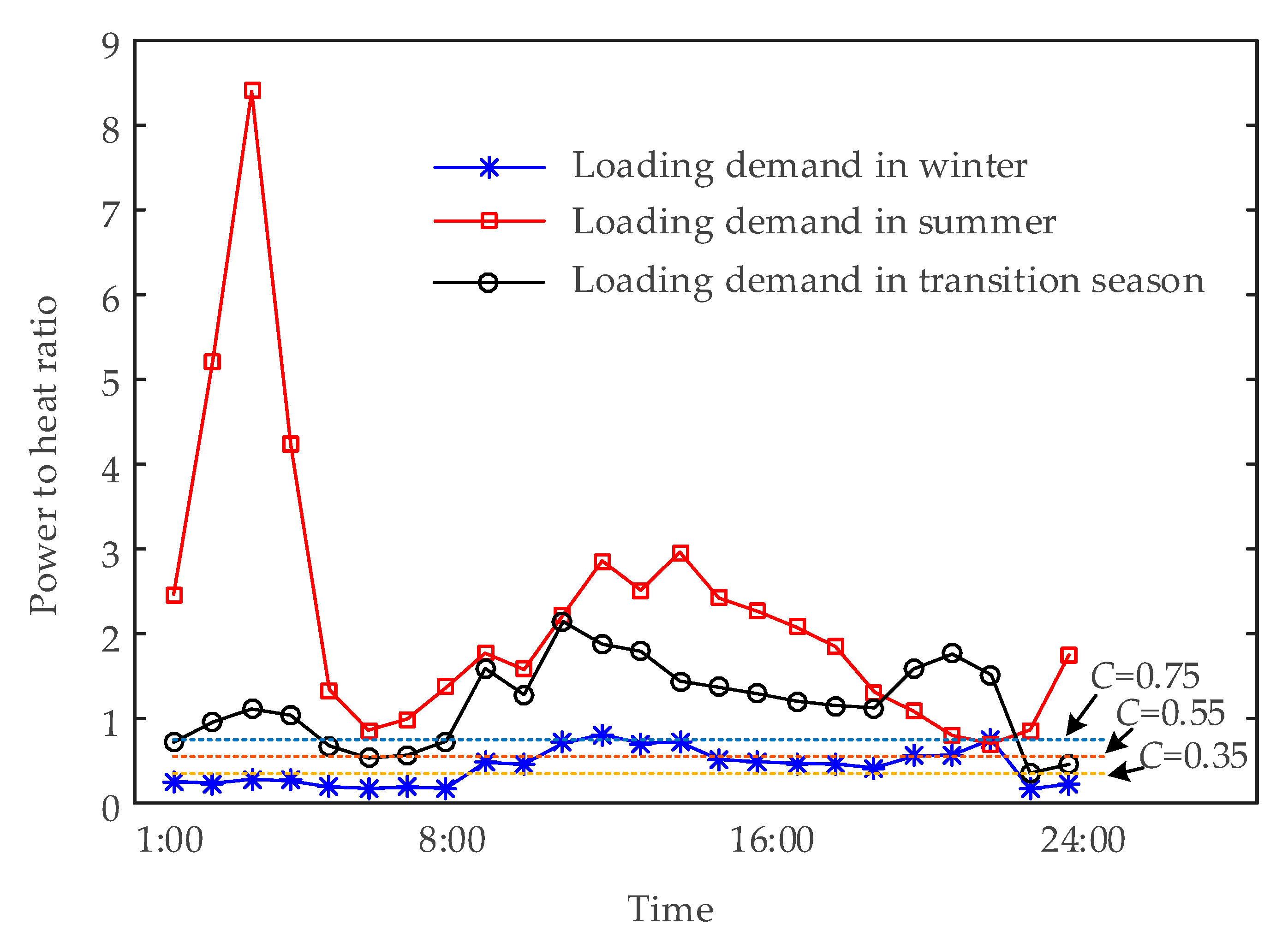
Through Table 2, it can be found that under FEL mode, the electric power system is not under the influence of CHP generation, while the overvoltage problem always happens. The different profiles of power and heating demand in diverse seasons show more severe impact on the gas system, while under-pressure problem occurs in summer and transition seasons. The requirements for thermal energy storage devices, no matter capacity or operation rate, are also related to the power and thermal demands. Figure 5 illustrates the ratios of power to thermal loading requirements under different seasons. In summer, the loading power to heat ratios are mostly over 0.75, indicating that the thermal energy is always over-produced while the power to heat ratio of the CHP generator is set as 0.35, 0.55 or 0.75. Therefore, under these situations, the TES devices are always storing energy. So the requirement of TES capacity is very large, resulting in unpractical operation. Same circumstances happen in transition seasons. Comparatively, the power to heat ratios of loading demands in winter are between 0.17 and 0.81, which match the setting power to heat ratios of the CHP generator better. Hence the request for thermal energy storage is much less critical, especially while the power to heat ratio of the CHP generator is 0.55. In conclusion, the CHP generator under FEL mode should be equipped with a proper power to heat ratio matching the loading demands well. As a result, the gas network is less impacted and TES devices can be less invested.
4.1.2. Operation under Conventional FTL Mode
Under conventional FTL mode, the thermal energy is produced according to the consumption requirement of heating loads, so no TES devices are required. The system states under different operation conditions are illustrated in Table 3, where major variables concerned are listed.
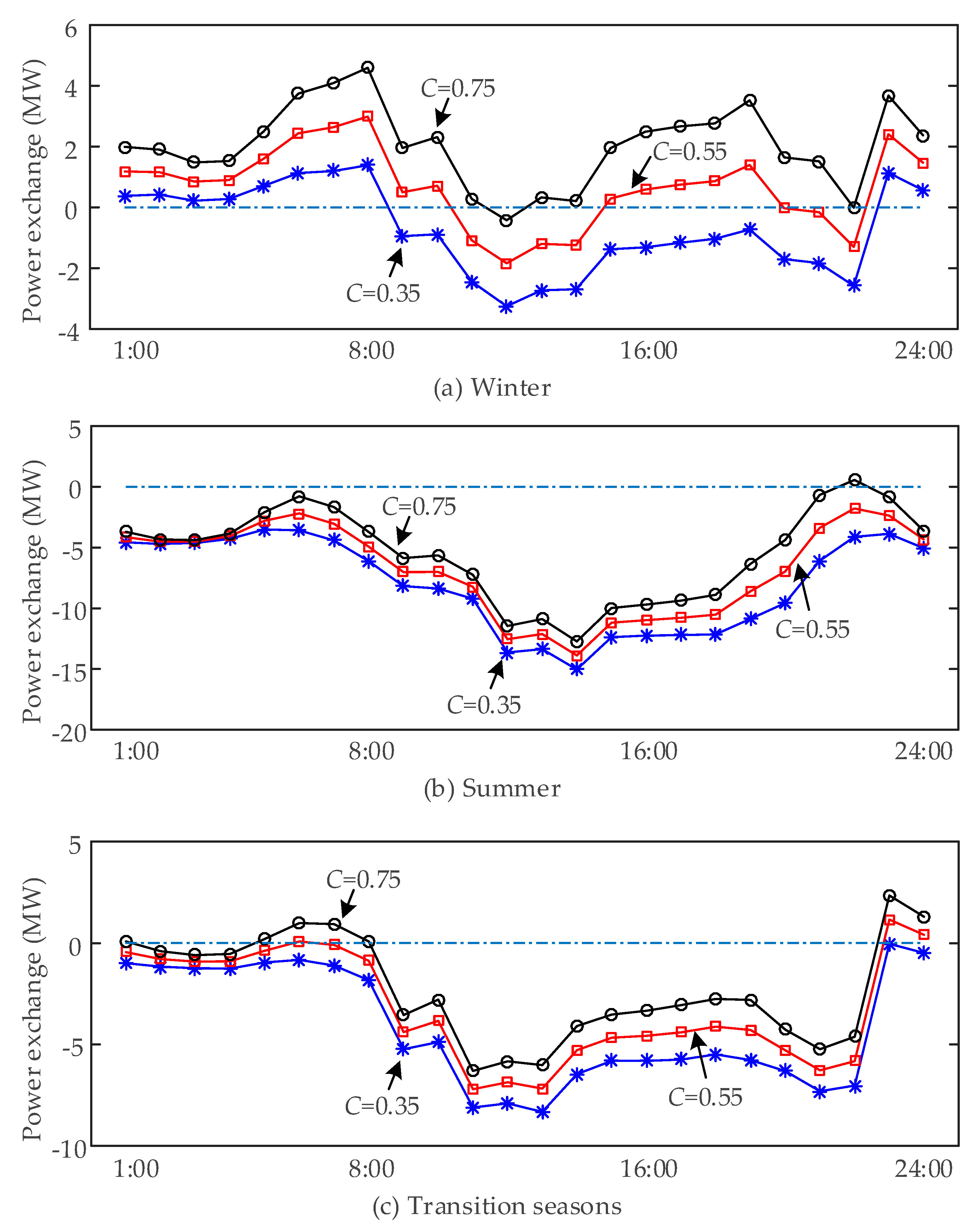
Through Table 3, it can be found that under FTL mode, the voltages in power networks and pressures in gas systems are all affected by CHP generation. In winter, because the power to heat ratio of loads and generations matches well, the electricity exchange between power networks and CHP systems is relatively small. However, the overvoltage problem seems more severe in this situation. This is due to the fact that overvoltage issues are caused by the DG injection and the effective way to mitigate the overvoltage is to consume more power in electric networks. Since the CHP system cannot afford high power consumption in winter, the power drawn from electric networks is limited. In summer and transition seasons, the overvoltage is alleviated remarkably. The reason is that in these seasons more electricity is required by CHP loads as shown in Figure 5, and the CHP generation following thermal demand cannot provide sufficient power. The electric system needs to supplement the lacking electricity. With more power consumed in power networks, the overvoltage problem is subsequently alleviated. The power exchanges between CHP systems and power networks are shown in Figure 6, where positive values denote power injection into electric systems and negative values refer to power consumption.
Combining Table 3 with Figure 6, it can be found that under FTL mode, higher power to heat ratio of CHP generation leads to more severe overvoltage problems in power electric networks. CHP systems with lower power to heat ratios generate less power under FTL mode and acquire more power from electric networks. Therefore, overvoltage issues are handled by extra power consumptions. As can be seen, the power to heat ratio of CHP generation significantly affects system states.
The CHP generation following electric loading expects the identical power to heat ratios of generation and loading demands. Meanwhile, the optimal power to heat ratio of CHP generation under FTL mode is constrained by the system states as well as loading demands. In both cases, the proportions of power and thermal demands are the pivotal concerns.
4.1.3. Operation under the Proposed Strategy
With the proposed strategy, the system states under different operation conditions are shown in Table 4. The proposed strategy prefers operating under conventional FTL mode, such as the case of summer with 0.35 power to heat ratio and transition season cases with 0.35 and 0.55 power to heat ratio. Under these situations, both the gas networks and electric systems are within proper operation states, so CHP generation is not required for auxiliary services. However, in other situations, either pressures in gas networks or voltages in electric systems are remarkably violated under conventional FTL mode. Hence the proposed strategy introduces new operation modes and the system operation is reset by coordinating with thermal storage devices. By implementing such policy, the under-pressure issues and overvoltage problems are all mitigated.
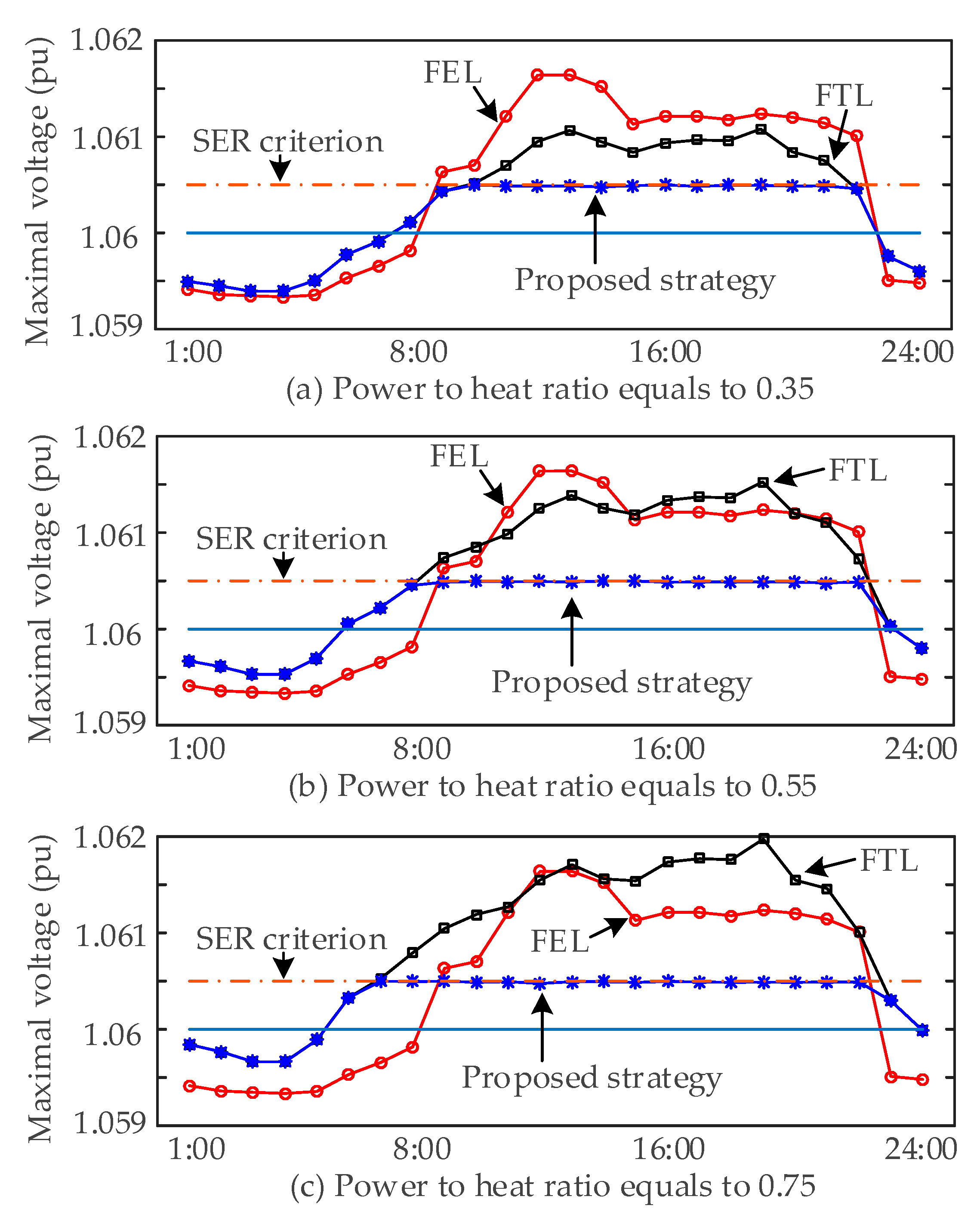
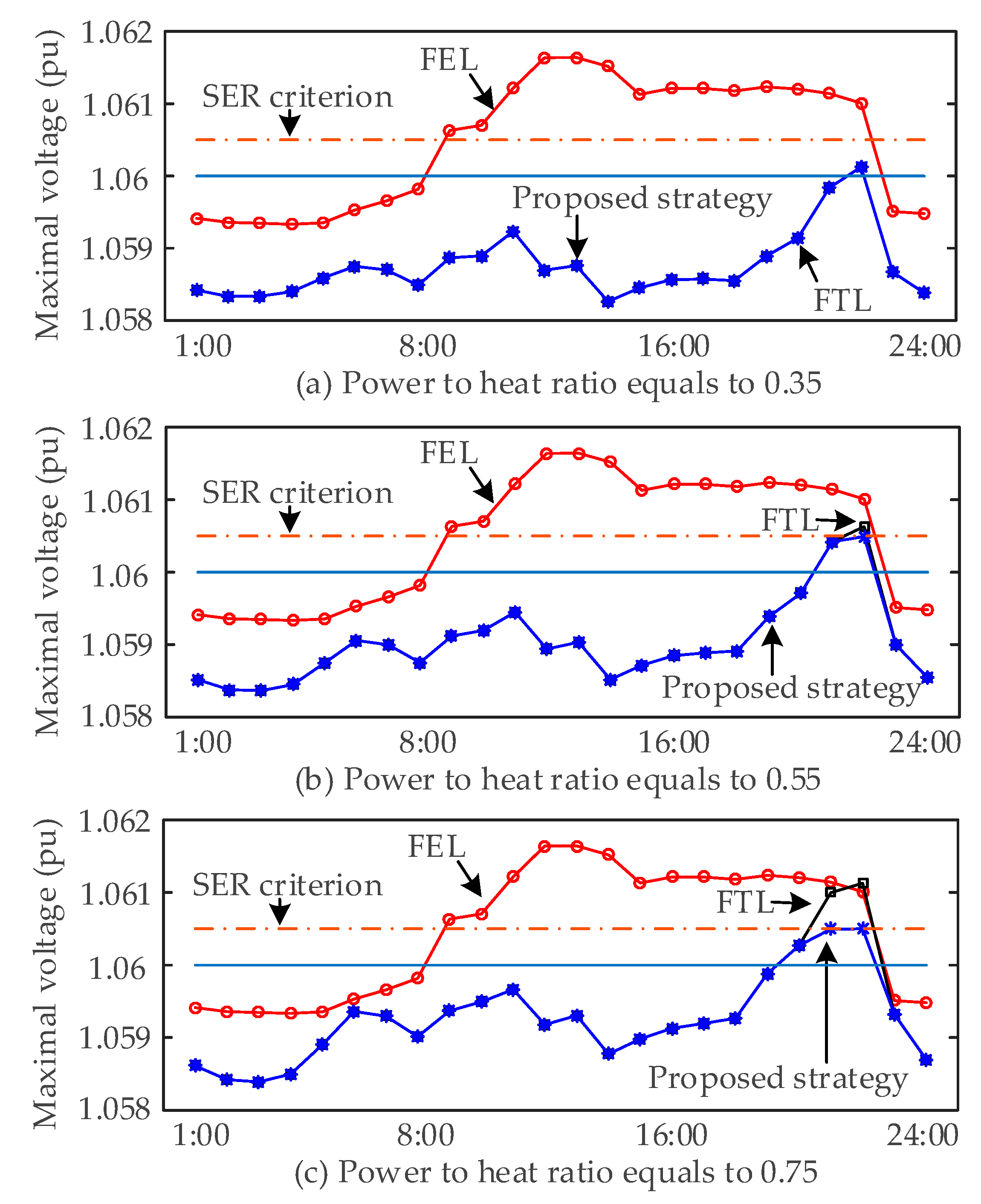
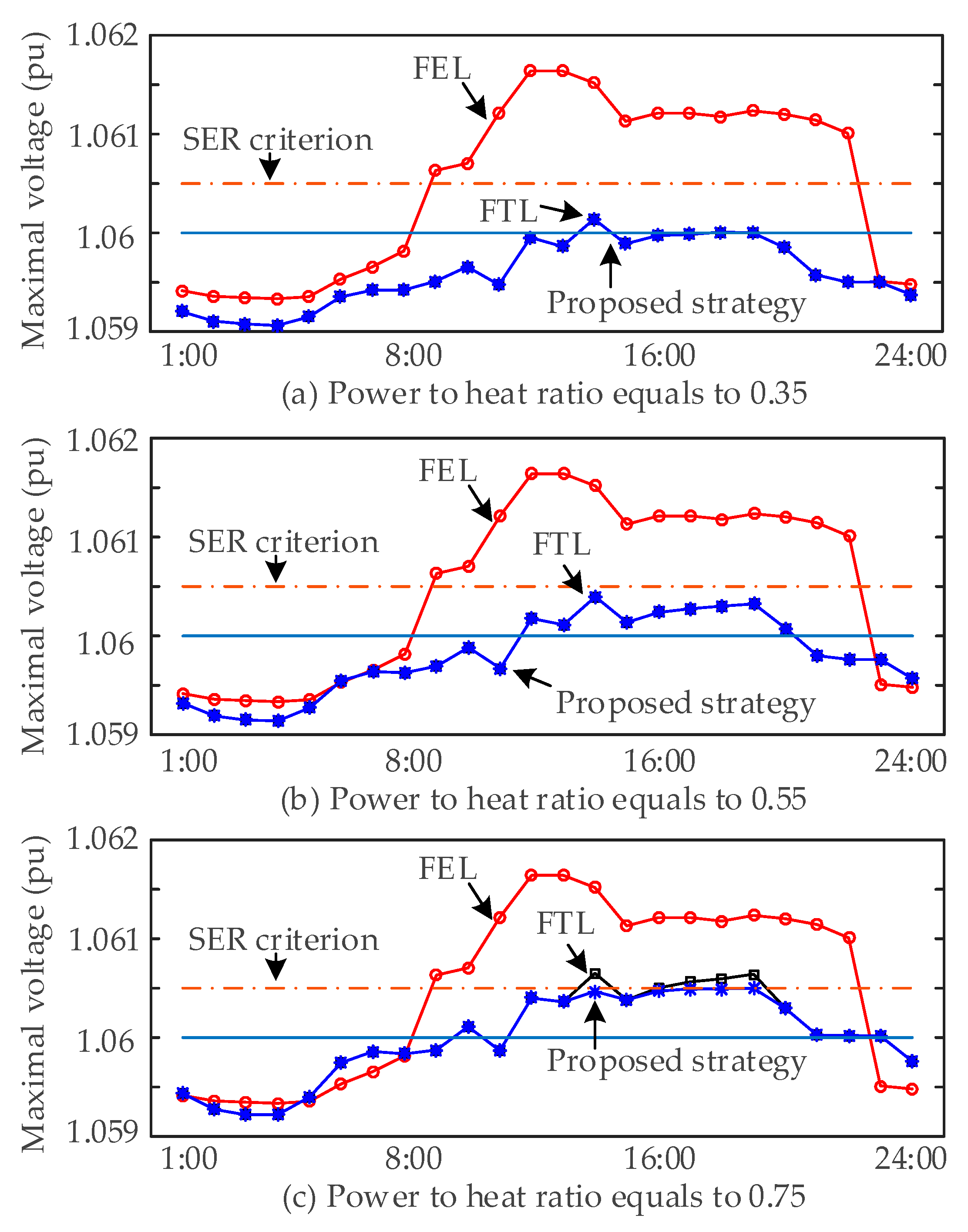
Figure 7, Figure 8 and Figure 9 illustrate the maximal voltages of all cases controlled by different strategies. When the CHP systems work under FEL mode, the electric networks always suffer from the overvoltage problems due to no effective interactions between the CHP generations and electric power networks. CHP systems under FTL mode do influence the system state of power networks, and this impact is related to the power to heat ratio of generation. Unfortunately, no matter which power to heat ratio is set, the overvoltage problem cannot be avoided in all seasons. The proposed strategy is activated for system management only when the abnormal conditions are detected. In summer and transition seasons shown in Figure 8 and Figure 9, the maximal voltages in electric systems under FTL mode are mostly within constraints, so the curves of the proposed strategy are almost overlapped with these of FTL mode. In addition, in other cases, all maximal voltages are controlled within defined SER criterion by implementing the proposed strategy, so as to minimal pressures in gas networks. It is clearly seen that the auxiliary services of CHP generations are fully utilized by introducing the proposed strategy.
4.1.4. Comparisons and Discussions
In order to give a clear picture on how the proposed strategy works, detailed information of selected cases is extended. Here two cases are further studied. One is winter case with 0.55 power to heat ratio, where overvoltage is the main concern. The other is summer case with 0.75 power to heat ratio, where under-pressure and overvoltage are both included.
Case 1. Winter Case with 0.55 Power to Heat Ratio
Table 5 shows the one day CHP operation modes in winter case with 0.55 power to heat ratio. While there is no overvoltage detected in the system, CHP system operates under FTL-TESO mode, which is consistent with conventional FTL mode. As soon as overvoltage is detected, it is desired to consume more power in electric networks. Therefore, CHP systems stop injecting power into electric networks and start consuming. Meanwhile, the power generation of CHP systems is also lowed to match the power balance, so the CHP systems switch to FEL mode. Since there is a lack of thermal supply, TES devices are responsible for this part and hence releasing the stored heat. FTL-TESO mode is switched to FEL-TESR mode.
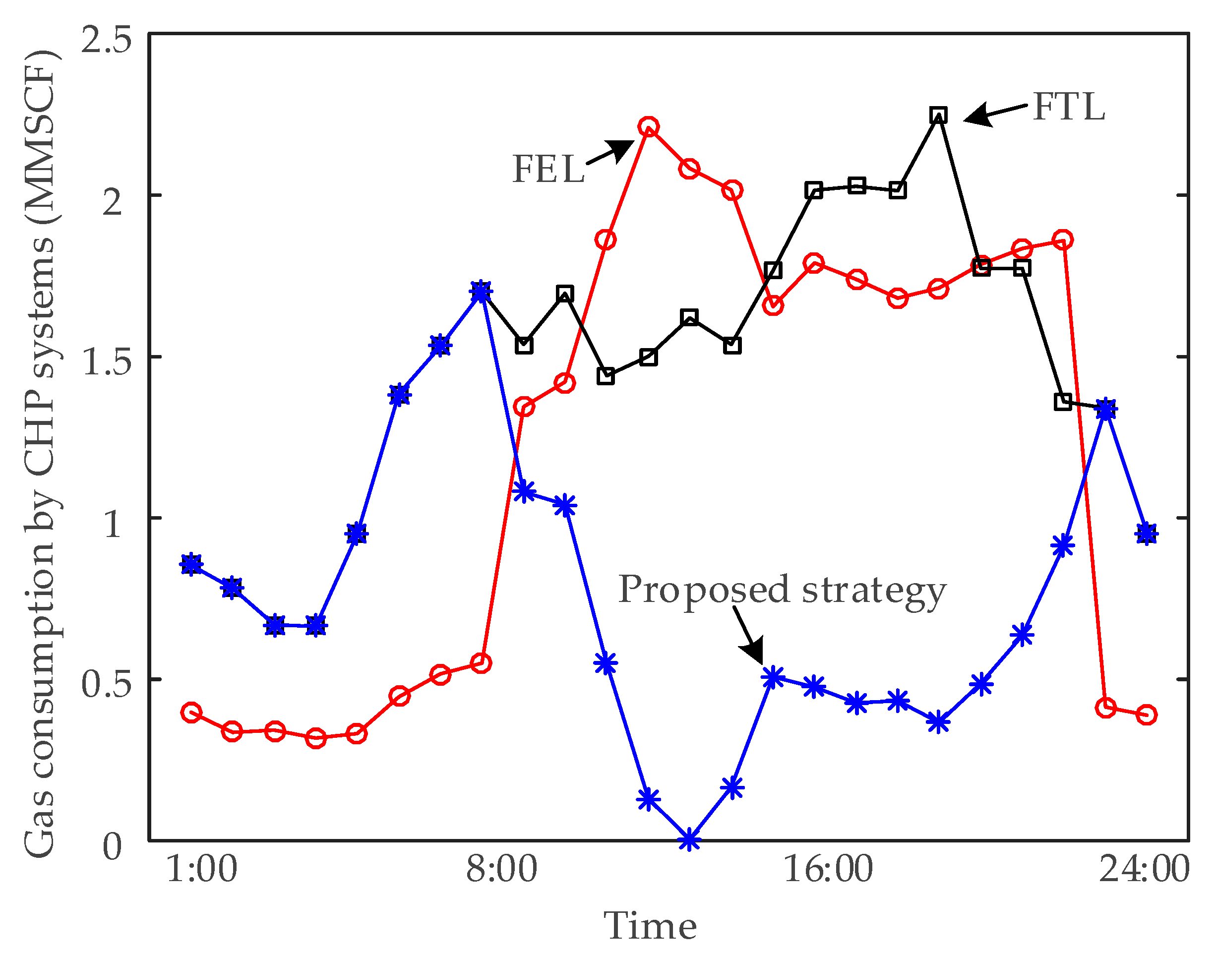
Figure 10 illustrates the gas consumption of the CHP system in winter case with 0.55 power to heat ratio. Under both FEL mode and FTL mode, the CHP systems consume remarkable quantities of natural gas while electric systems suffer from overvoltage issues simultaneously. These are unconscionable control strategies, resulting in abnormal system operation and primary energy wasting. Meanwhile, the gas consumption requirement by the proposed strategy is very small. The proposed strategy not only mitigates the overvoltage problems, but also saves the energy use in the hybrid energy systems, achieving desired benefits.
Case 2. Summer Case with 0.75 Power to Heat Ratio
Table 6 shows the one day CHP operation modes in summer case with 0.75 power to heat ratio. The CHP systems are mostly working under FTL-TESO mode, on account of the high ratio of power to heat demands. As seen in Figure 5, power demands in summer are very high, so the power produced by CHP generation following thermal loading cannot meet the electric loading requirement. The electric networks still supply a large amount of electricity and overvoltage is barely concerned. At 21:00, under-pressure issue is detected in hybrid systems, so the control mode is switched to FTL-TESR (Thermal energy releasing rate is 3.15 MW) based on the proposed strategy shown in Figure 4. At 22:00, the under-pressure is gone, but overvoltage happens. So the operation mode is set as FEL-TESR (Thermal energy releasing rate is 3.95 MW). By introducing these two modes, the whole system operation is guaranteed to be normal.
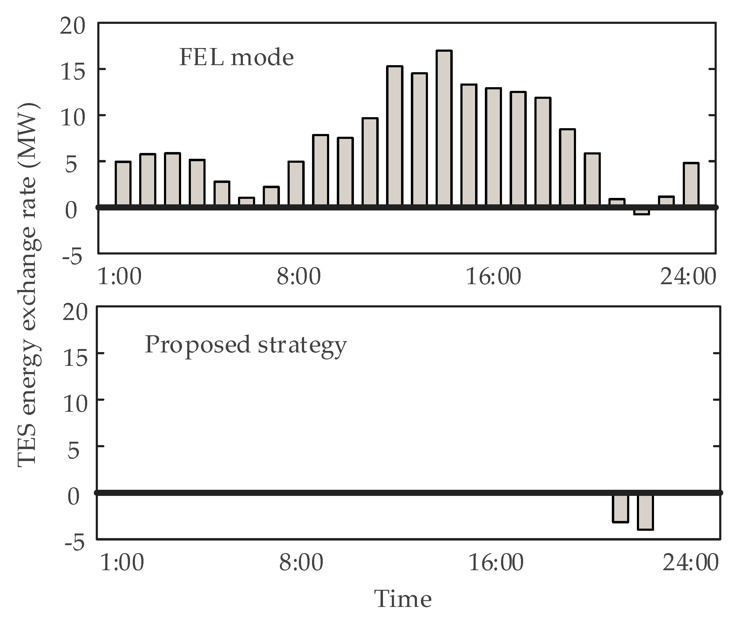
Figure 11 illustrates the TES energy exchange rate in summer case with 0.75 power to heat ratio, where positive values denote TES storing power and negative values denote TES releasing power. Since there is no TES involved in FTL mode, it is not illustrated. Under FEL mode, TES devices are frequently used, and the storing rate required is relatively high. Besides, high-frequency operations may reduce the service life of electric equipment. Under the proposed strategy, the TES devices are rarely operated. It indicates that the proposed strategy tries to control the system operations within the proper constraints by utilizing the features of the CHP generations themselves, rather than only depending on the additional equipment.
4.1.5. Impacts of Thermal Energy Storage
Based on studies shown above, further investigations on roles of thermal energy storage are conducted, while the TES capacities required in different scenarios are illustrated in Table 7. The proposed strategy requires some additional TES allocations compared with FTL strategy, but the amount of TES investment is very small in summer and transition seasons. Although TES requirement is relatively high in winter, the overall economic efficiency is not that reduced due to the energy saving benefits shown in Figure 10. Besides, considering the auxiliary services achieved through allocation of TES devices, the installment of TES is both technical and economic desired.
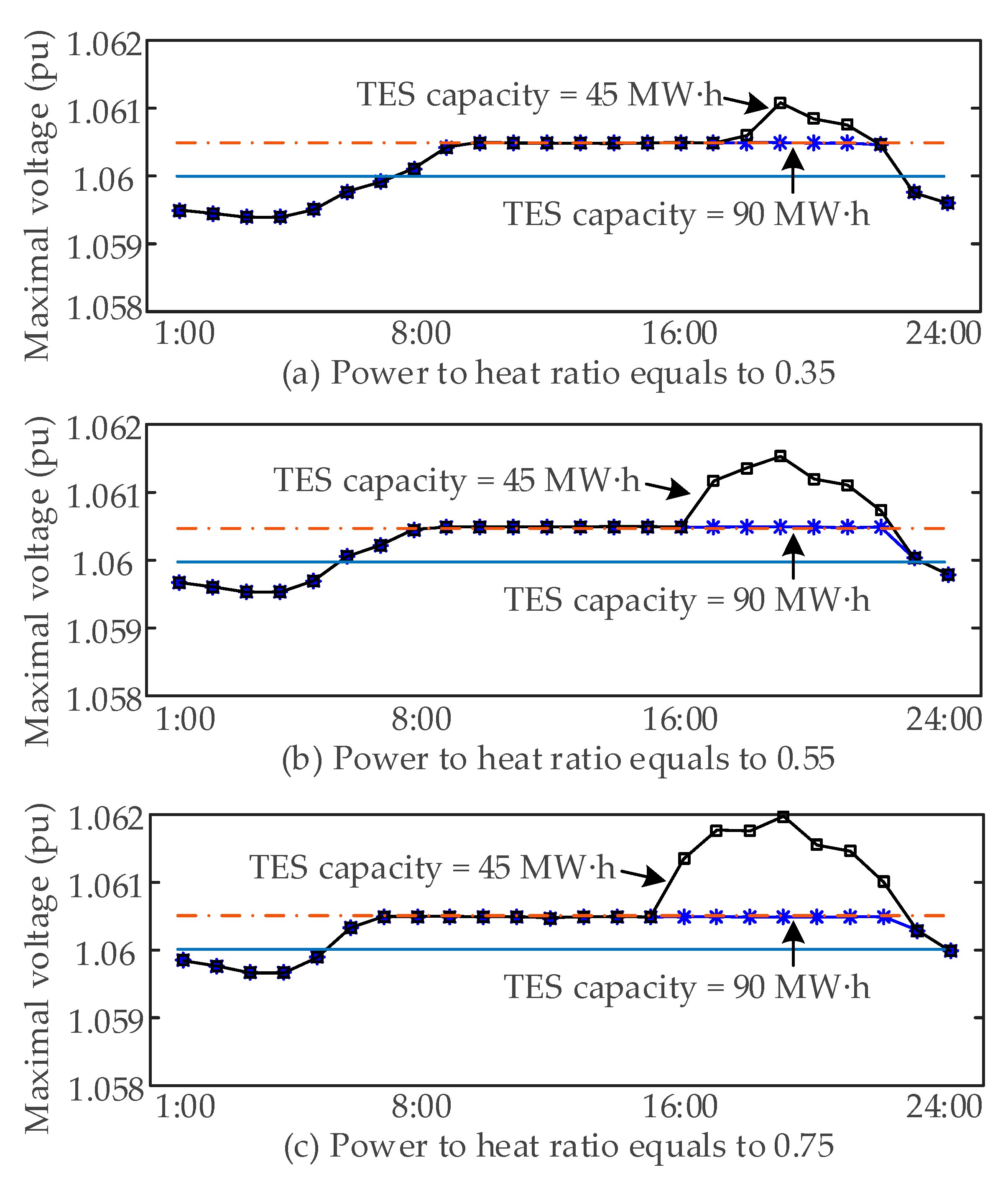
In the winter cases, the desired TES capacity for implementing the proposed strategy is 65, 80, and 90 MW∙h, respectively. However, if the capacity of actual TES devices installed with CHP systems is limited, the proposed strategy still achieves reasonable voltage regulation effect. Assume that the installed TES capacity is respectively 90 and 45 MW∙h, i.e., one is sufficiently allocated and the other is not. The voltage regulation results are shown in Figure 12. Though TES with 45 MW∙h is not able to mitigate all overvoltage issues, it helps to shorten the overvoltage durations, e.g., from 12h to 5 h in C = 0.35 case, from 14 h to 6h in C = 0.55 case, and from 16 h to 8 h in C = 0.75 case. The proposed strategy shows universal effectiveness in providing auxiliary services.
4.2. Hybrid Energy Systems with Double CHP Connections
In this case, two CHP systems are installed in the hybrid systems. One CHP unit connects node 3 of gas networks to node 46 of electric networks and is defined as CHP #1. The other CHP unit couples node 13 of gas networks to node 14 of electric networks, which is denoted as CHP #2. Since the impacts of power to heat ratio have already been investigated in previous subsection, in this part the power to heat ratio of CHP #1 is set as 0.75 while it is 0.55 for CHP #2. The rated power capacities of CHP units are both 20 MW. The optimization problem illustrated in Section 3.3 is solved by particle swarm optimization (PSO) to coordinate multiple CHP units.
4.2.1. General Control Performance
Based on diverse control strategies, the general system states are shown in Table 8. Under FEL mode, the CHP systems do not participate in the power network regulation and therefore overvoltage problem always exists. Besides, pressure abnormality happens in summer and transition seasons, when the power to heat ratio of loading demand is relatively high. Under FTL mode, overvoltage and under-pressure problems happen in both winter and summer. With the proposed strategy, the operation of the hybrid energy systems, including both natural gas networks and electric power networks, is always within proper constraints considering all season scenarios. Through the general results shown in Table 8, conclusion can be drawn that the proposed strategy is effective in the coordination of the hybrid energy system operations, ensuring the states of both subsystems within proper restraints.
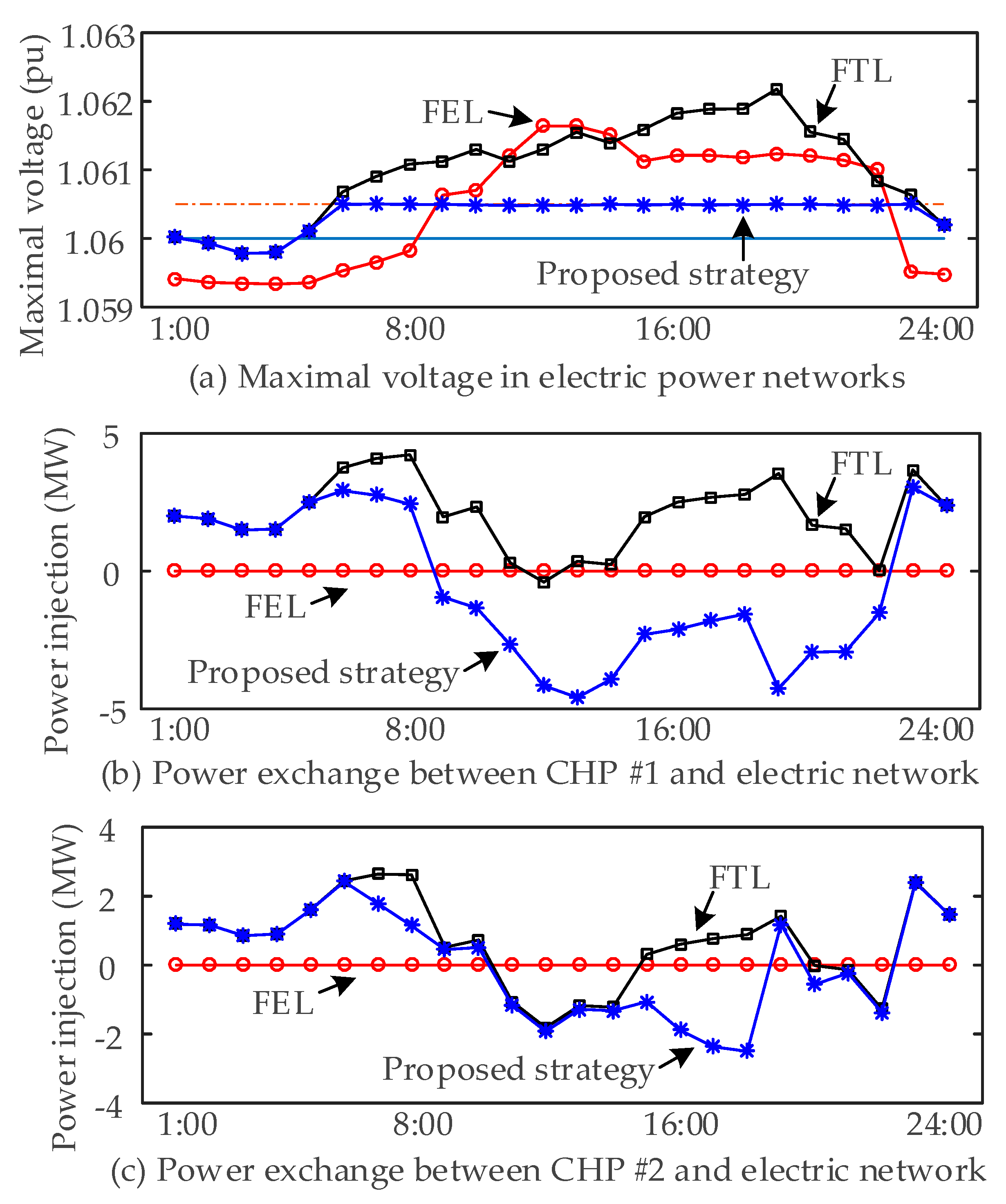
4.2.2. Control Performance on the Electric Power Networks
In this and next subsections, the detailed performance analyses are expanded based on the winter case, where all the typical concerns are included. The results of summer and transition seasons cases are similar and therefore not presented due to space limit.
Figure 13 shows the maximal voltages in electric networks and the power exchanges between CHP units and power systems. By implementing the proposed strategy, both CHP systems start to inject less or draw more power from the view of electric networks, which is effective in mitigating the overvoltage problem. Comparing with CHP #2, the CHP #1 injects more power into electric networks under FTL mode, and therefore it is regulated more under the proposed strategy.
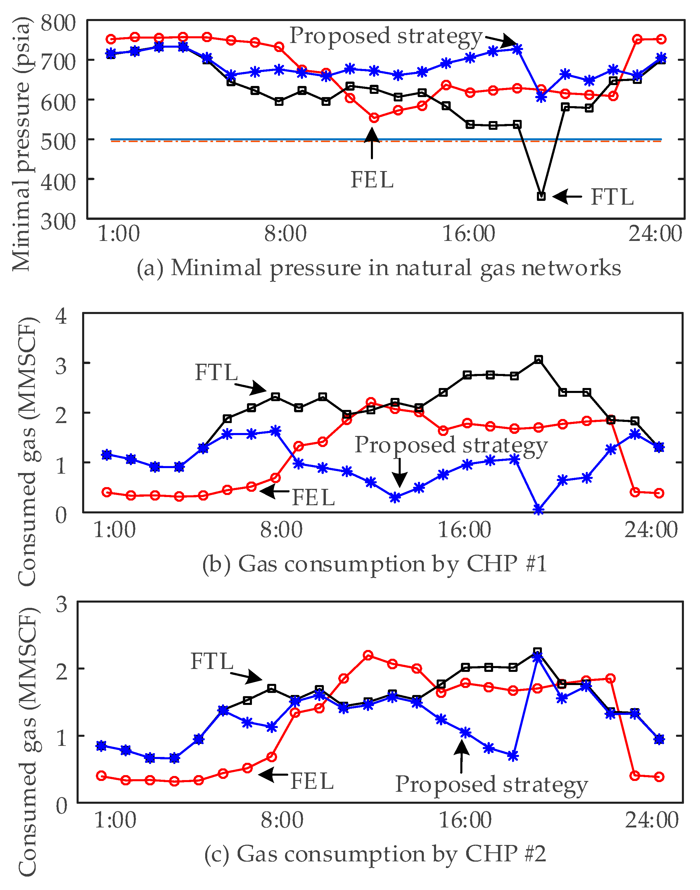
4.2.3. Control Performance on the Natural Gas Networks
Figure 14 shows the minimal pressure in natural gas networks and the gas consumption by two CHP units. Combined with Figure 13, following results can be obtained: (1) The gas pressure could be kept within proper ranges while the proposed strategy is implemented to mitigate the overvoltage issues, such as time period 6:00–18:00 and 20:00–23:00; (2) The proposed strategy is able to mitigate the pressure and voltage abnormality simultaneously, which is demonstrated at time 19:00; (3) Considering that the objective of coordination optimization is the minimum participation of TES, Figure 14b,c indicate that gas consumption of CHP units are decreased, resulting in energy saving achievements on the whole.
5. Conclusions
This paper has presented a novel control approach for combined heating and power generation. Hybrid energy systems are modeled at the first place. Then the criterion, named as state excursion rate, is defined to address the abnormality of system operations. By introducing thermal energy storages, the operation modes of CHP systems are significantly extended, providing better choices for system operations. Based on SER index, the optimal operation mode of combined electricity and gas systems is chosen, forming the key of the proposed approach. Case studies are tested on the hybrid energy systems, and the results demonstrate the superiority of this study. The proposed ideas and methods are verified to be capable of providing auxiliary services for both natural gas networks and electric power network operations by utilization of CHP system features. Besides, the desired economic and energy-efficient benefits are also maintained, and diverse power to heat ratios of CHP generations are well handled.
From the view of energy internet, the proposed study has provided an effective solution to the design and operation problems of the hybrid energy systems. By installation of thermal energy storages and further following the proposed control strategy, the CHP systems in combined electricity and natural gas networks are able to first eliminate the negative impact of themselves on the grid operations and then to provide effective auxiliary services to address operation abnormality. Meanwhile, the economic and energy-efficient benefits of the whole system are simultaneously maintained. The role of CHP systems in this study is changed from a passive single device to be an active response unit. The regulation capability of CHP systems is demonstrated in this paper as the first step, and the future work includes explorations of other types of energy hubs, integration of more energy forms and detailed economic analysis.
As an additional contribution to the energy internet, this study also provides a brand new visual angle dealing with hybrid energy issues, where benefits of all stakeholders are considered. Therefore, the proposed idea and approach are welcomed by grid operators, CHP owners, and even energy consumers, which makes the construction and application of energy internet more attractive to these interested parties.
Acknowledgments
This research is supported by State Grid Jiangsu Electric Power Company under Grant J2016015.
Author Contributions
Yu Liu performed the experiments and wrote the paper; Shan Gao conceived the idea; Xin Zhao designed the experiments; Chao Zhang analyzed the cases; Ningyu Zhang contributed the test data.
Conflicts of Interest
The authors declare no conflict of interest.
References
- Huang, A.Q.; Crow, M.L.; Heydt, G.T.; Zheng, J.P.; Dale, S.J. The Future Renewable Electric Energy Delivery and Management (FREEDM) System: The Energy Internet. Proc. IEEE 2010, 99, 133–148. [Google Scholar] [CrossRef]
- Rong, S.; Li, W.; Li, Z.; Sun, Y.; Zheng, T. Optimal allocation of thermal-electric decoupling systems based on the national economy by an improved conjugate gradient method. Energies 2016, 9, 17. [Google Scholar] [CrossRef]
- Destro, N.; Benato, A.; Stoppato, A.; Mirandola, A. Components design and daily operation optimization of a hybrid system with energy storages. Energy 2016, 117, 569–577. [Google Scholar] [CrossRef]
- Zhou, Z.; Zhang, J.; Liu, P.; Li, Z.; Georgiadis, M.C.; Pistikopoulos, E.N. A two-stage stochastic programming model for the optimal design of distributed energy systems. Appl. Energy 2013, 103, 135–144. [Google Scholar] [CrossRef]
- Kopanos, G.M.; Georgiadis, M.C.; Pistikopoulos, E.N. Energy production planning of a network of micro combined heat and power generators. Appl. Energy 2013, 102, 1522–1534. [Google Scholar] [CrossRef]
- Borelli, D.; Devia, F.; Cascio, E.L.; Schenone, C.; Spoladore, A. Combined Production and Conversion of Energy in an Urban Integrated System. Energies 2016, 9, 817. [Google Scholar] [CrossRef]
- Ju, L.; Tan, Z.; Li, H.; Tan, Q.; Yu, X.; Song, X. Multi-objective operation optimization and evaluation model for CCHP and renewable energy based hybrid energy system driven by distributed energy resources in China. Energy 2016, 111, 322–340. [Google Scholar] [CrossRef]
- Falke, T.; Krengel, S.; Meinerzhagen, A.K.; Schnettler, A. Multi-objective optimization and simulation model for the design of distributed energy systems. Appl. Energy 2016, 184, 1508–1516. [Google Scholar] [CrossRef]
- Kunitomi, K.; Kurita, A.; Tada, Y.; Ihara, S.; Prince, W.W.; Richardson, L.M.; Smith, G. Modeling combined-cycle power plant for simulation of frequency excursions. IEEE Trans. Power Syst. 2003, 18, 724–729. [Google Scholar] [CrossRef]
- Bao, Z.J.; Zhou, Q.; Yang, Z.H.; Yang, Q.; Xu, L.Z.; Wu, T. A multi time-scale and multi energy-type coordinated microgrid scheduling solution—Part I: Model and methodology. IEEE Trans. Power Syst. 2014, 30, 2257–2266. [Google Scholar] [CrossRef]
- Mago, P.J.; Fumo, N.; Chamra, L.M. Performance analysis of CCHP and CHP systems operating following the thermal and electric load. Int. J. Energy Res. 2009, 33, 852–864. [Google Scholar] [CrossRef]
- Heinonen, J.; Laine, J.; Pluuman, K.; Säynäjoki, E.S.; Soukka, R.; Junnila, S. Planning for a low carbon future? Comparing heat pumps and cogeneration as the energy system options for a new residential area. Energies 2015, 8, 9137–9154. [Google Scholar] [CrossRef]
- Jalazadeh-Azar, A.A. A Comparison of Electrical- and Thermal-Load-Following CHP Systems. ASHRAE Trans. 2004, 110, 85–94. [Google Scholar]
- Fang, F.; Wang, Q.H.; Shi, Y. A Novel Optimal Operational Strategy for the CCHP System Based on Two Operating Modes. IEEE Trans. Power Syst. 2012, 27, 1032–1041. [Google Scholar] [CrossRef]
- Brahman, F.; Jadid, S. Optimal Energy Management of Hybrid CCHP and PV in a Residential Building. In Proceedings of the 2014 19th International Conference on Electrical Power Distribution Networks (EPDC 2014), Vienna, Austria, 6–7 May 2014. [Google Scholar]
- Reza, H. A developed offline model for optimal operation of combined heating and cooling and power systems. IEEE Trans. Energy Convers. 2009, 24, 222–229. [Google Scholar] [CrossRef]
- Cascio, E.L.; Borelli, D.; Devia, F.; Schenone, C. Future distributed generation: An operational multi-objective optimization model for integrated small scale urban electrical, thermal and gas grids. Energy Convers. Manag. 2017, 143, 348–359. [Google Scholar] [CrossRef]
- Gu, C.; Xie, D.; Sun, J.; Wang, X.; Ai, Q. Optimal Operation of Combined Heat and Power System Based on Forecasted Energy Prices in Real-Time Markets. Energies 2015, 8, 14330–14345. [Google Scholar] [CrossRef]
- Li, M.; Mu, H.; Li, H. Analysis and Assessments of Combined Cooling, Heating and Power Systems in Various Operation Modes for a Building in China, Dalian. Energies 2013, 6, 2446–2467. [Google Scholar] [CrossRef]
- Fumo, N.; Chamra, L.M. Analysis of combined cooling, heating, and power systems based on source primary energy consumption. Appl. Energy 2010, 87, 2023–2030. [Google Scholar] [CrossRef]
- Gu, W.; Wu, Z.; Bo, R.; Liu, W.; Zhou, G.; Chen, W.; Wu, Z. Modeling, planning and optimal energy management of combined cooling, heating and power microgrid: A review. Int. J. Electr. Power Energy Syst. 2014, 54, 26–37. [Google Scholar] [CrossRef]
- Geidl, M.; Andersson, G. Optimal Power Flow of Multiple Energy Carriers. IEEE Trans. Power Syst. 2007, 22, 145–155. [Google Scholar] [CrossRef]
- Martínez-Mares, A.; Fuerte-Esquivel, C.R. A unified gas and power flow analysis in natural gas and electricity coupled networks. IEEE Trans. Power Syst. 2012, 27, 2156–2166. [Google Scholar] [CrossRef]
- Li, Q.; An, S.; Thomas, W.G. Solving natural gas load flow problems using electric load flow techniques. In Proceedings of the North American Power Symposium, Rolla, MO, USA, 20–21 October 2003. [Google Scholar]
- Chen, S.; Sun, G.; Wei, Z.; Wang, D.; Sun, Y.H.; Zang, H.X.; Zhu, Y. Probabilistic Energy Flow Analysis in Integrated Electricity and Natural-gas Energy systems. Proc. CSEE. 2015, 35, 6331–6340. [Google Scholar] [CrossRef]
- Frangopoulos, C.A. A method to determine the power to heat ratio, the cogenerated electricity and the primary energy savings of cogeneration systems after the European Directive. Energy 2012, 45, 52–61. [Google Scholar] [CrossRef]
- Combined Heat and Power Technology Assessment. Available online: https://energy.gov/sites/prod/files/2015/02/f19/QTR%20Ch8%20-%20CHP%20TA%20Feb-13-015.pdf (accessed on 13 February 2017).
- Yu, Z.F.; Li, C. Ensure Total Efficiency and Ratio of Heat and Power in Distributed Energy Supply System. Shanghai Energy Conserv. 2005, 6, 42–44. [Google Scholar]
- Yang, M.H.; Ruan, Y.J.; Li, Z.Y.; Zeng, G. Simulation of Hourly Cooling Heating and Electrical Load in CCHP System. Refrig. Air Cond. Electr. Power Mach. 2009, 30, 85–95. [Google Scholar]
- Smith, A.D.; Mago, P.J.; Fumo, N. Benefits of thermal energy storage option combined with CHP system for different commercial building types. Sustain. Energy Technol. Assess. 2013, 1, 3–12. [Google Scholar] [CrossRef]
Figure 1.
Framework of CHP based hybrid energy networks.

Figure 2.
Compressor driven by a gas turbine.

Figure 3.
24 h energy consumption proportion. (a) Winter; (b) Summer; (c) Transition season.

Figure 4.
Coordinated operation and control strategy of hybrid energy system.

Figure 5.
Power to heat ratios of demands under different seasons.

Figure 6.
Power exchanges between CHP generation and power networks.

Figure 7.
Maximal voltages under different control strategies in winter (power to heat ratio of CHP generation is set with diverse value, where (a) C = 0.35; (b) C = 0.55; and (c) C = 0.75).
Figure 7.
Maximal voltages under different control strategies in winter (power to heat ratio of CHP generation is set with diverse value, where (a) C = 0.35; (b) C = 0.55; and (c) C = 0.75).

Figure 8.
Maximal voltages under different control strategies in summer (power to heat ratio of CHP generation is set with diverse value, where (a) C = 0.35; (b) C = 0.55; and (c) C = 0.75).
Figure 8.
Maximal voltages under different control strategies in summer (power to heat ratio of CHP generation is set with diverse value, where (a) C = 0.35; (b) C = 0.55; and (c) C = 0.75).

Figure 9.
Maximal voltages under different control strategies in transition seasons (power to heat ratio of CHP generation is set with diverse value, where (a) C = 0.35; (b) C = 0.55; and (c) C = 0.75).
Figure 9.
Maximal voltages under different control strategies in transition seasons (power to heat ratio of CHP generation is set with diverse value, where (a) C = 0.35; (b) C = 0.55; and (c) C = 0.75).

Figure 10.
Gas consumptions following different control strategies (Winter, C = 0.55).

Figure 11.
TES energy exchange in summer case with 0.75 power to heat ratio.

Figure 12.
Impacts of TES capacity on voltage regulation (power to heat ratio of CHP generation is set with diverse value, where (a) C = 0.35; (b) C = 0.55; and (c) C = 0.75).
Figure 12.
Impacts of TES capacity on voltage regulation (power to heat ratio of CHP generation is set with diverse value, where (a) C = 0.35; (b) C = 0.55; and (c) C = 0.75).

Figure 13.
Control performance on the power electric networks ((a) Maximal voltage in electric power networks (b) Power exchange between CHP #1 and electric network (c) Power exchange between CHP #2 and electric network).
Figure 13.
Control performance on the power electric networks ((a) Maximal voltage in electric power networks (b) Power exchange between CHP #1 and electric network (c) Power exchange between CHP #2 and electric network).

Figure 14.
Control performance on the natural gas networks ((a) Minimal pressure in natural gas networks (b) Gas consumption by CHP #1 (c) Gas consumption by CHP #2).
Figure 14.
Control performance on the natural gas networks ((a) Minimal pressure in natural gas networks (b) Gas consumption by CHP #1 (c) Gas consumption by CHP #2).


Table 1.
Typical technical parameters of representative gas turbine based CHP generation system.
| Power/kW | Heating/kW | C | ηe (%) | η (%) | |
|---|---|---|---|---|---|
| 1 | 250 | 341 | 0.733 | 29.99 | 70.88 |
| 2 | 610 | 1733 | 0.352 | 18.88 | 72.52 |
| 3 | 1435 | 3202 | 0.448 | 23.59 | 76.23 |
| 4 | 2825 | 6411 | 0.441 | 23.22 | 75.92 |
| 5 | 5265 | 9298 | 0.566 | 28.91 | 79.96 |
Table 2.
System states under different power to heat ratio based CHP generations (FEL mode).
| Season | State Variable | Power to Heat Ratio of GT Based Generator | ||
|---|---|---|---|---|
| 0.35 | 0.55 | 0.75 | ||
| Winter | Maximal voltage (pu) | 1.0616 | 1.0616 | 1.0616 |
| Minimal voltage (pu) | 0.9587 | 0.9587 | 0.9587 | |
| Maximal pressure (psia) | 1254 | 1254 | 1254 | |
| Minimal pressure (psia) | 604 | 604 | 604 | |
| TES capacity required (MW∙h) | 70 | 30 | 65 | |
| TES storing rate required (MW) | 0.57 | 3.35 | 9.30 | |
| TES releasing rate required (MW) | 6.12 | 5.43 | 3.95 | |
| Summer | Maximal voltage (pu) | 1.0616 | 1.0616 | 1.0616 |
| Minimal voltage (pu) | 0.9587 | 0.9587 | 0.9587 | |
| Maximal pressure (psia) | 1350 | 1350 | 1350 | |
| Minimal pressure (psia) | 220 | 220 | 220 | |
| TES capacity required (MW∙h) | 550 | 295 | 175 | |
| TES storing rate required (MW) | 42.95 | 25.24 | 16.97 | |
| TES releasing rate required (MW) | / | / | 0.75 | |
| Transition seasons | Maximal voltage (pu) | 1.0616 | 1.0616 | 1.0616 |
| Minimal voltage (pu) | 0.9587 | 0.9587 | 0.9587 | |
| Maximal pressure (psia) | 1225 | 1225 | 1225 | |
| Minimal pressure (psia) | 435 | 435 | 435 | |
| TES capacity required (MW∙h) | 285 | 140 | 75 | |
| TES storing rate required (MW) | 23.80 | 13.11 | 8.41 | |
| TES releasing rate required (MW) | / | 2.11 | 3.14 | |
Table 3.
System states under different power to heat ratio based CHP generations (FTL mode).
| Season | State Variable | Power to Heat Ratio of GT Based Generator | ||
|---|---|---|---|---|
| 0.35 | 0.55 | 0.75 | ||
| Winter | Maximal voltage (pu) | 1.0611 | 1.0615 | 1.0620 |
| Minimal voltage (pu) | 0.9588 | 0.9588 | 0.9589 | |
| Maximal pressure (psia) | 1246 | 1223 | 1208 | |
| Minimal pressure (psia) | 646 | 602 | 551 | |
| Maximal power injection by CHP (MW) | 1.38 | 2.99 | 4.59 | |
| Maximal power consumption by CHP (MW) | 3.26 | 1.84 | 0.42 | |
| Summer | Maximal voltage (pu) | 1.0601 | 1.0606 | 1.0611 |
| Minimal voltage (pu) | 0.9583 | 0.9583 | 0.9583 | |
| Maximal pressure (psia) | 1263 | 1260 | 1262 | |
| Minimal pressure (psia) | 625 | 564 | 456 | |
| Maximal power injection by CHP (MW) | / | / | 0.56 | |
| Maximal power consumption by CHP (MW) | 15.03 | 13.88 | 12.73 | |
| Transition seasons | Maximal voltage (pu) | 1.0601 | 1.0604 | 1.0606 |
| Minimal voltage (pu) | 0.9586 | 0.9586 | 0.9587 | |
| Maximal pressure (psia) | 1262 | 1251 | 1238 | |
| Minimal pressure (psia) | 654 | 634 | 605 | |
| Maximal power injection by CHP (MW) | / | 1.16 | 2.36 | |
| Maximal power consumption by CHP (MW) | 8.33 | 7.21 | 6.31 | |
Table 4.
System states under different power to heat ratio based CHP generations. (Following the proposed strategy).
Table 4.
System states under different power to heat ratio based CHP generations. (Following the proposed strategy).
| Season | State Variable | Power to Heat Ratio of GT Based Generator | ||
|---|---|---|---|---|
| 0.35 | 0.55 | 0.75 | ||
| Winter | Maximal voltage (pu) | 1.0605 | 1.0605 | 1.0605 |
| Minimal voltage (pu) | 0.9588 | 0.9588 | 0.9589 | |
| Maximal pressure (psia) | 1278 | 1278 | 1277 | |
| Minimal pressure (psia) | 654 | 633 | 612 | |
| TES capacity required (MW∙h) | 65 | 80 | 90 | |
| TES storing rate required (MW) | / | / | / | |
| TES releasing rate required (MW) | 7.88 | 8.89 | 9.37 | |
| Maximal power injection by CHP (MW) | 1.38 | 2.99 | 3.95 | |
| Maximal power consumption by CHP (MW) | 5.44 | 5.42 | 5.47 | |
| Summer | Maximal voltage (pu) | 1.0601 | 1.0605 | 1.0605 |
| Minimal voltage (pu) | 0.9583 | 0.9583 | 0.9583 | |
| Maximal pressure (psia) | 1263 | 1262 | 1265 | |
| Minimal pressure (psia) | 625 | 563 | 500 | |
| TES capacity required (MW∙h) | / | 2 | 7 | |
| TES storing rate required (MW) | / | / | / | |
| TES releasing rate required (MW) | / | 1.20 | 3.95 | |
| Maximal power injection by CHP (MW) | / | / | / | |
| Maximal power consumption by CHP (MW) | 15.03 | 13.88 | 12.73 | |
| Transition seasons | Maximal voltage (pu) | 1.0601 | 1.0604 | 1.0605 |
| Minimal voltage (pu) | 0.9586 | 0.9586 | 0.9587 | |
| Maximal pressure (psia) | 1262 | 1251 | 1233 | |
| Minimal pressure (psia) | 654 | 634 | 621 | |
| TES capacity required (MW∙h) | / | / | 4 | |
| TES storing rate required (MW) | / | / | / | |
| TES releasing rate required (MW) | / | / | 1.14 | |
| Maximal power injection by CHP (MW) | / | 1.16 | 2.36 | |
| Maximal power consumption by CHP (MW) | 8.33 | 7.21 | 6.31 | |
Table 5.
CHP operation modes under the proposed control strategy in winter case (C = 0.55).
| Time | 1:00 | 2:00 | 3:00 | 4:00 | 5:00 | 6:00 |
| Mode | FTL-TESO | FTL-TESO | FTL-TESO | FTL-TESO | FTL-TESO | FTL-TESO |
| PEPN (MW) | 1.18 | 1.16 | 0.85 | 0.90 | 1.60 | 2.44 |
| Time | 7:00 | 8:00 | 9:00 | 10:00 | 11:00 | 12:00 |
| Mode | FTL-TESO | FTL-TESO | FEL-TESR | FEL-TESR | FEL-TESR | FEL-TESR |
| PEPN (MW) | 2.64 | 2.99 | −0.68 | −0.98 | −3.40 | −5.40 |
| Time | 13:00 | 14:00 | 15:00 | 16:00 | 17:00 | 18:00 |
| Mode | FEL-TESR | FEL-TESR | FEL-TESR | FEL-TESR | FEL-TESR | FEL-TESR |
| PEPN (MW) | −5.42 | −4.80 | −2.98 | −3.41 | −3.40 | −3.24 |
| Time | 19:00 | 20:00 | 21:00 | 22:00 | 23:00 | 24:00 |
| Mode | FEL-TESR | FEL-TESR | FEL-TESR | FEL-TESR | FTL-TESO | FTL-TESO |
| PEPN (MW) | −3.49 | −3.37 | −3.11 | −2.46 | 2.41 | 1.47 |
Table 6.
CHP operation modes under the proposed control strategy in summer case (C = 0.75).
| Tim | 1:00 | 2:00 | 3:00 | 4:00 | 5:00 | 6:00 |
| Mode | FTL-TESO | FTL-TESO | FTL-TESO | FTL-TESO | FTL-TESO | FTL-TESO |
| PEPN (MW) | −3.71 | −4.33 | −4.40 | −3.86 | −2.09 | −0.79 |
| Time | 7:00 | 8:00 | 9:00 | 10:00 | 11:00 | 12:00 |
| Mode | FTL-TESO | FTL-TESO | FTL-TESO | FTL-TESO | FTL-TESO | FTL-TESO |
| PEPN (MW) | −1.67 | −3.72 | −5.88 | −5.65 | −7.25 | −11.46 |
| Time | 13:00 | 14:00 | 15:00 | 16:00 | 17:00 | 18:00 |
| Mode | FTL-TESO | FTL-TESO | FTL-TESO | FTL-TESO | FTL-TESO | FTL-TESO |
| PEPN (MW) | −10.89 | −12.73 | −9.99 | −9.69 | −9.38 | −8.90 |
| Time | 19:00 | 20:00 | 21:00 | 22:00 | 23:00 | 24:00 |
| Mode | FTL-TESO | FTL-TESO | FTL-TESR | FEL-TESR | FTL-TESO | FTL-TESO |
| PEPN (MW) | −6.34 | −4.39 | −3.04 | −2.40 | −0.87 | −3.61 |
Table 7.
Thermal energy storage requirements in different scenarios (unit: MW∙h).
| Seasons | Control Mode | Diverse C Based GT Generator in CHP System | ||
|---|---|---|---|---|
| C = 0.35 | C = 0.55 | C = 0.75 | ||
| Winter | FEL | 70 | 30 | 65 |
| FTL | 0 | 0 | 0 | |
| Proposed strategy | 65 | 80 | 90 | |
| Summer | FEL | 550 | 295 | 175 |
| FTL | 0 | 0 | 0 | |
| Proposed strategy | 0 | 2 | 7 | |
| Transition seasons | FEL | 285 | 140 | 75 |
| FTL | 0 | 0 | 0 | |
| Proposed strategy | 0 | 0 | 4 | |
Table 8.
System states under different control strategy based CHP generations.
| Season | State Variable | Control Strategy | ||
|---|---|---|---|---|
| FEL | FTL | Proposed Strategy | ||
| Winter | Maximal voltage (pu) | 1.0616 | 1.0622 | 1.0605 |
| Minimal voltage (pu) | 0.9587 | 0.9590 | 0.9590 | |
| Maximal pressure (psia) | 1400 | 1320 | 1320 | |
| Minimal pressure (psia) | 554 | 356 | 607 | |
| TES capacity required for CHP #1 (MW∙h) | 65 | / | 75 | |
| Maximal power injected by CHP #1 (MW) | / | 4.22 | 3.04 | |
| Maximal power consumed by CHP #1 (MW) | / | 0.40 | 4.60 | |
| TES capacity required for CHP #2 (MW∙h) | 30 | / | 25 | |
| Maximal power injected by CHP #2 (MW) | / | 2.64 | 2.42 | |
| Maximal power consumed by CHP #2 (MW) | / | 1.81 | 2.50 | |
| Summer | Maximal voltage (pu) | 1.0616 | 1.0609 | 1.0605 |
| Minimal voltage (pu) | 0.9587 | 0.9679 | 0.9579 | |
| Maximal pressure (psia) | 1580 | 1422 | 1429 | |
| Minimal pressure (psia) | 380 | 244 | 500 | |
| TES capacity required for CHP #1 (MW∙h) | 175 | / | 5 | |
| Maximal power injected by CHP #1 (MW) | / | 0.56 | / | |
| Maximal power consumed by CHP #1 (MW) | / | 12.73 | 12.73 | |
| TES capacity required for CHP #2 (MW∙h) | 295 | / | 15 | |
| Maximal power injected by CHP #2 (MW) | / | / | / | |
| Maximal power consumed by CHP #2 (MW) | / | 13.88 | 13.88 | |
| Transition seasons | Maximal voltage (pu) | 1.0616 | 1.0602 | 1.0602 |
| Minimal voltage (pu) | 0.9587 | 0.9586 | 0.9586 | |
| Maximal pressure (psia) | 1340 | 1390 | 1390 | |
| Minimal pressure (psia) | 252 | 612 | 612 | |
| TES capacity required for CHP #1 (MW∙h) | 70 | / | / | |
| Maximal power injected by CHP #1 (MW) | / | 2.36 | 2.36 | |
| Maximal power consumed by CHP #1 (MW) | / | 6.31 | 6.31 | |
| TES capacity required for CHP #2 (MW∙h) | 140 | / | / | |
| Maximal power injected by CHP #2 (MW) | / | 1.16 | 1.16 | |
| Maximal power consumed by CHP #2 (MW) | / | 7.21 | 7.21 | |
© 2017 by the authors. Licensee MDPI, Basel, Switzerland. This article is an open access article distributed under the terms and conditions of the Creative Commons Attribution (CC BY) license (http://creativecommons.org/licenses/by/4.0/).
Share and Cite
MDPI and ACS Style
Liu, Y.; Gao, S.; Zhao, X.; Zhang, C.; Zhang, N. Coordinated Operation and Control of Combined Electricity and Natural Gas Systems with Thermal Storage. Energies 2017, 10, 917. https://doi.org/10.3390/en10070917
AMA Style
Liu Y, Gao S, Zhao X, Zhang C, Zhang N. Coordinated Operation and Control of Combined Electricity and Natural Gas Systems with Thermal Storage. Energies. 2017; 10(7):917. https://doi.org/10.3390/en10070917
Chicago/Turabian StyleLiu, Yu, Shan Gao, Xin Zhao, Chao Zhang, and Ningyu Zhang. 2017. "Coordinated Operation and Control of Combined Electricity and Natural Gas Systems with Thermal Storage" Energies 10, no. 7: 917. https://doi.org/10.3390/en10070917
Note that from the first issue of 2016, this journal uses article numbers instead of page numbers. See further details here.