Article

Design of an Enhanced FLC-Based Controller for Selective Harmonic Compensation in Active Power Filters

by
Odair de Barros Junior
*,
Thiago Silva Amorim
,
Daniel Carletti
,
Anselmo Frizera Neto
and
Lucas Frizera Encarnação
Department of Electrical Engineering, Federal University of Espírito Santo, Vitória ES 29075-910, Brazil
*
Author to whom correspondence should be addressed.
Electronics 2020, 9(12), 2052; https://doi.org/10.3390/electronics9122052
Submission received: 5 November 2020 / Revised: 17 November 2020 / Accepted: 17 November 2020 / Published: 3 December 2020
(This article belongs to the Section Power Electronics)

Abstract

:
The increasing number of electronic loads has introduced several harmonics into the power system, leading to a growth in the importance of filters intended for their mitigation. Thus, it is important to have the knowledge to select operational limits of each new filter connected in the power grid. Likewise, obtaining these harmonics requires robust tracking systems that provide enough information for better filter selectivity. This paper proposes a selective harmonic active filter control based on Fourier linear combiner (FLC) algorithms for a three-phase electrical grid. The presented system is enabled to track each harmonic order and sequence components with great robustness, extracting positive, negative, and zero sequence information from each harmonic for further filter selectivity. It also proposes a new strategy to improve the FLC-based algorithms in tracking frequencies in power grid disturbances. Simulated results of the algorithm and a real-time simulation of a selective active power filter (SAPF) were presented, validating the performance in several scenarios.

1. Introduction

Signal processing applied to the power grid has become an increasingly relevant tool in power electronics applications. The advance of power electronics devices allows for a real time control of power grid variables, ensuring greater efficiency in energy processing, such as power quality conditioning [1]. Several applications require connections between the grid and power electronic converters which demands synchronization, the ability to reject disturbances, as well as fast tracking of specific frequencies and other features in order to generate a suitable reference signal for the converter, such as a Static Synchronous Compensator (STATCOM) and active filters. Among the signal tracking strategies widely applied for synchronization, the most common in the literature are the phase-locked loops based on instantaneous active and reactive power theory (p-q theory) and second order generalized integrator (SOGI) [2,3]. These strategies seek robustness and a low response time in the phase tracking of fundamental positive and negative sequence components of a signal.
Even so, with the increasing penetration of automated systems dedicated to the electrical grid management comes the need for a greater amount of information regarding the involved voltages and currents with a fast response and low computational cost.
Selective active power filters (SAPF), for example, require real time data of the harmonic and phase sequence components to mitigate unwanted powers [4]. Thus, in order to achieve harmonic tracking, some versions of SOGI and other strategies based on fast Fourier transforms (FFT) have been proposed in the literature [5,6,7]. The SOGI modifications consists in an association of multiple SOGIs to track harmonic components, increasing the SOGI computational cost and the errors likelihood. However, FFT strategies have a higher built-in computational cost and power loss errors if the sampling rate is not a multiple value of the period, very common during variations in the grid fundamental frequency [8,9,10].
A possible alternative is the use of a Fourier linear combiner (FLC) to perform the tracking of fundamental and harmonic components. The FLC is a variation of the least mean square (LMS) algorithm, widely found in biomedical engineering literature for tracking human tremors, which allows the real time decomposition of a periodic signal in its Fourier series [11,12,13]. A FLC modification, the weighted-frequency Fourier linear combiner (WFLC), implements the tracking of the greater magnitude component present in a periodic signal [14,15]. According to current and voltage stability requirements, it allows the fundamental frequency tracking, and many designers use a combination of FLC and WFLC to simplify the process of tuning the WFLC and FLC. These strategies, in conjunction with Kalman Filters or notch filters, are found in the literature for grid voltage synchronization, although a large part of them focus on fundamental amplitude tracking [5,6,7,8,9,10]. However, since the great advantage of this strategy is the intrinsic way of tracking harmonic and fundamental components, there is a possibility to further explore this characteristic, expanding the number of information obtained from the power grid. This has already been verified through simulation to act on three-phase systems with high harmonic penetration and as a control for selective filters to mitigate zero sequence components. This is accomplished by using an adaptation for three-phase systems named SDFLC [16]. Therefore, this paper presents an improvement of the WFLC frequency tracking, reducing the noise in the WFLC operation in the presence of higher magnitude harmonics. To verify the efficiency of this new structure along with the SDFLC, a real time simulation of a SAPF is conducted. This WFLC improvement, the 3WFLC, uses three WFLCs to readjust the fundamental frequency, avoiding the use of low-pass filters for noise reduction, making the SDFLC robust against harmonic noise without compromising the phase delay [16,17,18,19].
The structure of this paper is as follows. Section 2 presents the concepts of FLC-based algorithms and the improvements, SDFLC and 3WFLC, proposed in this paper for a power grid application. Section 3 presents the simulation results for the proposed algorithms and a brief comparison with SOGI and other FLC-based strategies. Section 4 presents the test-bench and real-time simulation results for a SAPF using the proposed algorithm and the discussion about the results obtained. Lastly, Section 5 presents the conclusions.

2. Fourier Linear Combiner-Based Algorithms

The Fourier linear combiner (FLC) is an application of the Least Mean Square (LMS) algorithm to estimate the weights of a Fourier series corresponding to an original periodic signal. Several uses of this algorithm can be found in biomedical engineering literature [11,12,13,14,15,16,17], and its theoretical bases are clearly addressed in several papers in the same literature [11,12]. The FLC works with an adaptive step μ limited by the maximum number of harmonics to be estimated, from the equations
x r k = { sin ( r ω 0 k ) ,   1 r M cos [ ( r M ) ω 0 k ] ,   M + 1 r 2 M
ε k = s k W k T X k
W k + 1 = W k + 2 μ X k ε k
where W k is the adaptive weight vector, X k is the x r k vector, M is the number of harmonics in the model, r denotes the harmonic index and s k is the input signal for a k sample.
The FLC has low computational cost and inherently zero phase error [20]. The FLC operates only for a stationary fundamental frequency. Considering the possible frequency variations due to disturbances in the power grid, the weighted-frequency Fourier linear combiner (WFLC) readjusts the frequency component of greatest magnitude present in the original signal [14,15]. This adaptation can be obtained through a modified LMS algorithm, according to the equation
ω 0 k + 1 = ω 0 k + 2 μ 0 ε k r = 1 M r ( ω r k x M + r k ω M + r k x r k )
where ω 0 is the frequency of the greater magnitude component, ε k denotes the system deviation and μ 0 is the adaptive step for the modified LMS. The FLC and WFLC diagrams are shown in Figure 1.
It is conventional to use the WFLC and the FLC together to simplify the tuning of both algorithms, designating the WFLC only to readjust the frequency [18,19,20,21,22,23,24].
In three-phase systems, both algorithms are joined to form the structure shown in Figure 2. Each phase has a WFLC/FLC combination to decompose the original signals into a Fourier series. However, instead of recomposing the signals at the end of the process, a Fortescue transform determine the sequential components of each harmonic tracked by the FLCs. This structure is the sequence detector Fourier linear combiner (SDFLC). To improve the frequency estimated by them, a combination of three WFLCs is used in the SDFLC in this paper, instead of just one as was done in previously works [18].
The output of the Fortescue Transform is the following equations:
y p k = W p k X p k + W p 120 k X p k + W p + 120 k X p k
y p k = W p k X p k + W p 120 k X p + 120 k + W p + 120 k X p 120 k
y p 0 k = W p k X p k + W p 120 k X p 120 k + W p + 120 k W p + 120 k
where y denotes the output signal for each harmonic, p is the phase in three-phase systems.
SDFLC has trigonometric components in its algorithms, increasing the computational costs, however, it has the advantage of intrinsically track harmonic and sequence components. Thus, it is a robust option for tracking non-conventional harmonic and sequence components from the power grid.
The deviations in frequency readjustment by WFLC can be classified by the noise due to the influence of harmonic components and white noise. While single-phase solutions require a Low-Pass Filter to reduce this noise [22], three-phase systems can rely on information from other phases to mitigate noise. White noise has no correlation with the original signal, so a simple average of the frequencies obtained from each WFLC can mitigate this noise. For harmonic components noise deviations, they are mainly due to the presence of third and fifth harmonic components of greater magnitudes. Since those harmonics are conventionally present in zero and negative sequence components, respectively, its influence can be mitigated by avoiding the tracking of the negative and zero sequence with a modified LMS, the three-phase weighted-frequency Fourier linear combiner (3WFLC). The adapted frequency ω 0 is then the average of the following frequencies obtained in each phase:
ω a 0 k + 1 =   ω a 0 k + 2 μ 0 ε a k r - 1 M r   ( w a r k x a ( M + r ) k + w a ( M + r ) k x a r k )
ω b 0 k + 1 =   ω b 0 k + 2 μ 0 ε b k r - 1 M r   ( w b r k x a ( M + r ) k + w b ( M + r ) k x a r k )
ω c 0 k + 1 =   ω c 0 k + 2 μ 0 ε c k r - 1 M r   ( w c r k x a ( M + r ) k + w c ( M + r ) k x a r k )
ω 0 k + 1 = ω a 0 k + 1 + ω b 0 k + 1 + ω c 0 k + 1 3
which allows for more robust adapted frequencies when compared to the original WFLC.

3. Simulation Tests

3.1. Simulation Scenarios Description

The design process for the 3WFLC and SDFLC involves the choosing of the adaptive weights for the LMS and modified LMS algorithms. Such weights are determined empirically, defining only the maximum stability limits and the best response time to a sinusoidal signal with 1 pu, 60 Hz, and 0° parameters. The maximum limits for adaptive weights are related to the highest harmonic to be tracked. For the tuning, the 23rd harmonic was adopted as the largest tracked harmonic component, thus the highest value of adaptive weights that guarantees the stability of the algorithm is 0.0434. Since the 3WFLC will only track the fundamental component, its maximum limit for adaptive weight is 1. The SDFLC and 3WFLC were simulated in the PSCAD/EMTDC to tune all adaptive weights. The configuration parameters of the PSCAD simulation are presented in Table 1, and the values found for each of the algorithms are shown in Table 2.
Some simulation scenarios are also proposed to verify the algorithm efficiency in tracking harmonic and symmetric components. Due to its relevance in literature, multiple second-order generalized integrators and frequency-locked loop(MSOGI-FLL) is also subjected to the same scenarios and the results of both algorithms are compared [8,9]. The MSOGI-FLL proposed in this paper is designed to track zero sequence components, which, although not usual for this strategy, is suitable for the proper harmonic tracking in proposed scenarios. In scenarios where there are frequency transients, the comparison is also performed with the FLC proposed in the literature using the same adaptive weights presented in Table 2. The configuration parameters of MSOGI-FLL are presented in Table 3.

3.2. Simulation Results

The simulation scenarios proposed in this paper were developed to demonstrate the behavior of SDFLC + 3WFLC in the occurrence of several electrical grid disturbances. The MSOGI-FLL and, in frequency results, the original WFLC were used to establish parameters for comparison with SDFLC + 3WFLC. The proposed simulation scenarios are presented in Table 4.
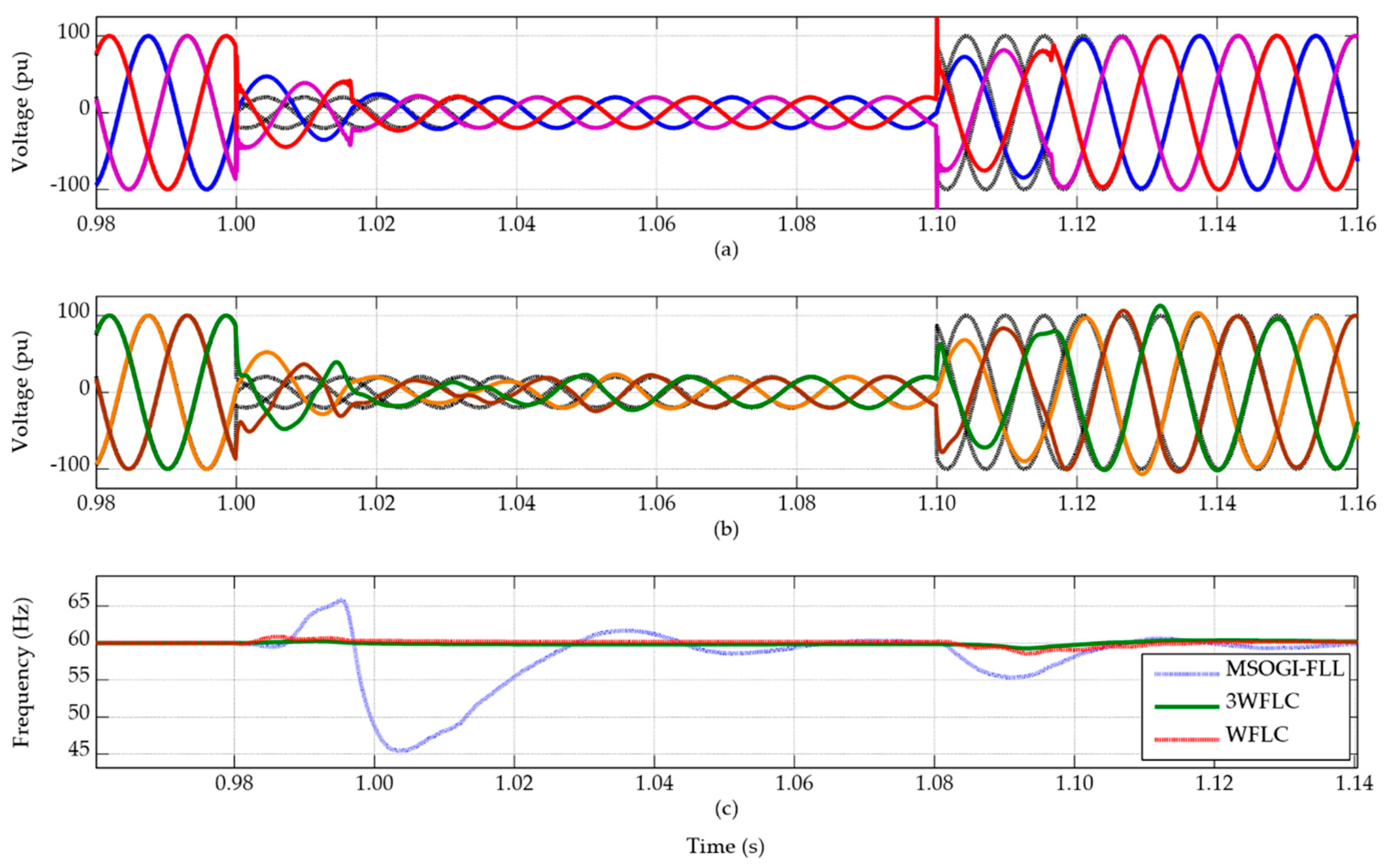
In SC1, the power grid suffers a voltage drop from 1 pu to 0.2 pu peak-to-peak in 1.0 s, returning to nominal voltage in 1.1 s. In this scenario, the algorithms synchronization time with the original signal after the sudden voltage variations and the frequency transients caused by this variation were observed. Figure 3 presents the voltage results for SDFLC and MSOGI-FLL and frequency results for 3WFLC, WFLC, and MSOGI-FLL.
The sudden voltage variation caused a disturbance in frequency tracking. After the voltage sag, the SDFLC and MSOGI synchronize again with the original signal in one cycle and two cycles respectively. In frequency tracking, 3WFLC presented a smaller frequency sag of 59.2 Hz, while WFLC and MSOGI-FLL presented 58.8 Hz and 45.5 Hz respectively.
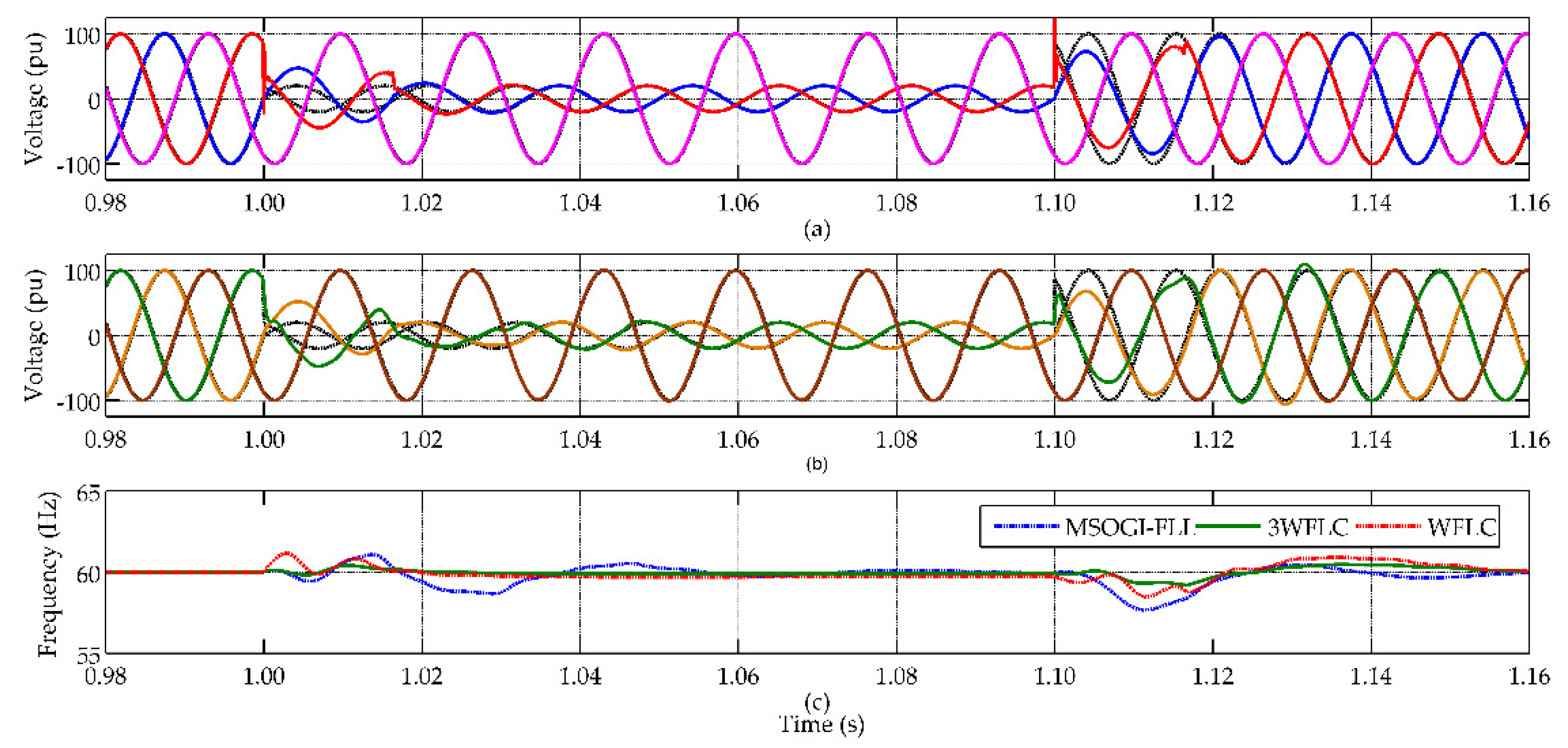
In SC2, the power grid suffers an asymmetric voltage sag in phases A and C from 1 pu to 0.2 pu peak-to-peak in 1.0 s, returning to nominal voltage in 1.1 s. Once again, the synchronization time of the algorithms with the original signal and frequency disturbances were observed. Figure 4 presents the voltage results for SDFLC and MSOGI-FLL and frequency results for 3WFLC, WFLC, and MSOGI-FLL.
The sudden voltage variation in phases A and C caused a disturbance in frequency tracking. After the voltage sag, the SDFLC and MSOGI synchronize again with the original signal in one cycle and two cycles respectively. In frequency tracking, 3WFLC presented the smaller frequency sag of 59.2 Hz, while WFLC and MSOGI-FLL presented 58.8 Hz and 57.7 Hz respectively.
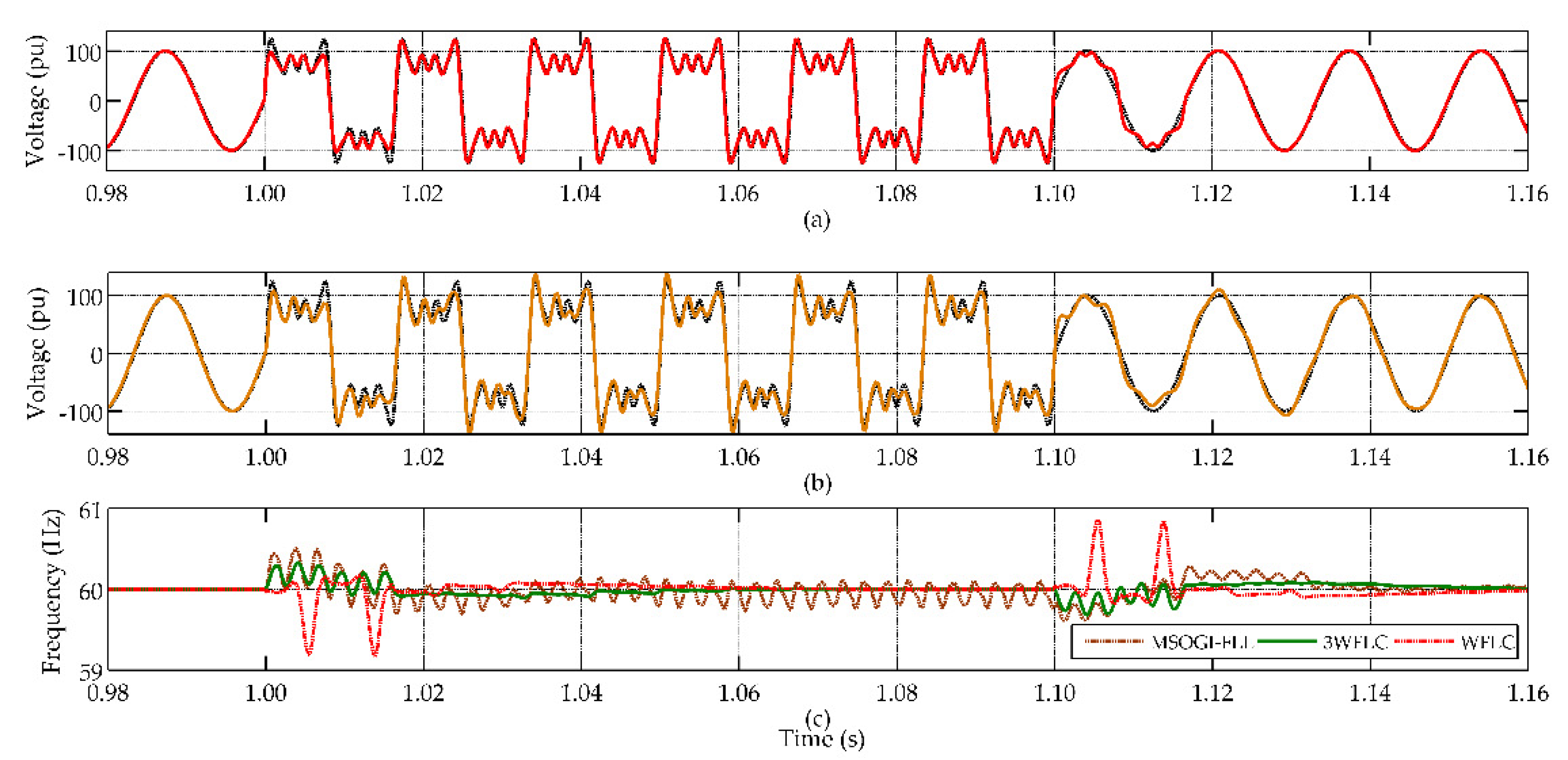
The SC3 is a harmonic injection scenario. From instant 1.0 s to 2.1 s, the 3rd, 5th, 7th, and 11th harmonic components are injected in the power grid according to its conventional symmetrical components and the Total harmonic Distortion (THD) is 65%. Figure 5 presents the voltage results for SDFLC and MSOGI-FLL and frequency results for 3WFLC, WFLC, and MSOGI-FLL.
After the disturbance, the harmonic components were tracked in one cycle by SDFLC and two cycles by MSOGI-FLL. The high harmonic injection caused an oscillating deviation in MSOGI-FLL, and a maximum frequency of 60.5 Hz. A maximum of 60.9 Hz and 60.3 Hz was observed in WFLC and 3WFLC respectively. It is also possible to observe that both FLC strategies show a minor oscillation around the frequency during harmonic injection and the 3WFLC presents the minor overshooting.
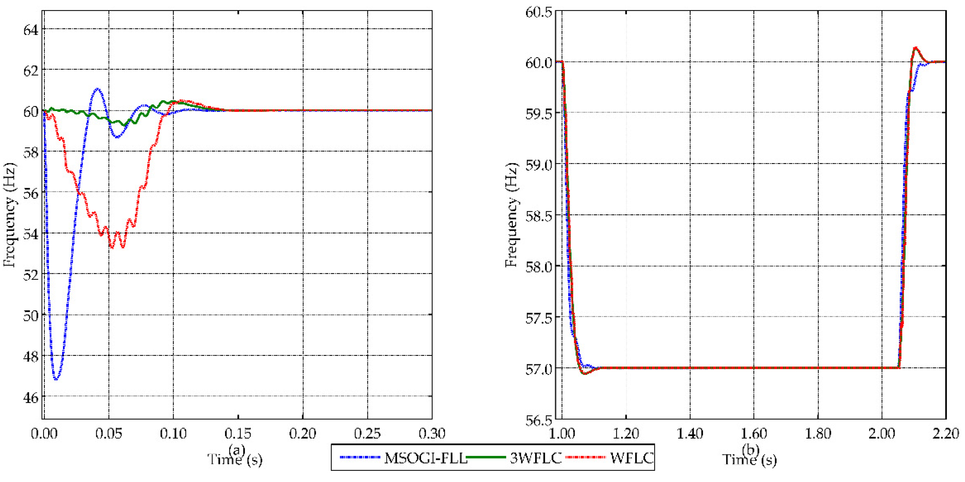
The SC4 is about frequency variation in two different moments. The first analyzes the behavior of the strategies after the start of voltage measurements in the power grid. The second is the sudden variation of the signal fundamental frequency from 60 Hz to 57 Hz for 1.1 s. Figure 6 presents the frequency results.
In Figure 6a, after the measuring starts, the three strategies presented an overshooting until synchronization at 12.5 ms. The maximum overshoot presented was 47 Hz, 54.5 Hz and 59.5 Hz for MSOGI-FLL, WFLC and 3WFLC respectively. In Figure 6b, the three strategies achieved similar behavior, synchronizing with the new frequencies at 1.15 s and 2.15 s. The WFLC and 3WFLC had a 60.15 Hz overshoot, while MSOGI-FLL did not have any overshoot.
After analyzing the different proposed scenarios, it is possible to compare the three strategies. The SDFLC + 3WFLC showed a minor voltage and frequency deviation in SC1 and SC2. Also, SDFLC + 3WFLC presented better transient performance and lesser settling time. In addition, 3WFLC didn’t present any behavior difference for symmetrical or asymmetrical drop in SC1 and SC2, which was expected because 3WFLC tracks fundamental positive sequence frequency and therefore is more robust in the face of asymmetrical disturbs. Throughout the SC3, SDFLC + 3WFLC showed a minor frequency overshooting and better performance on frequency tracking than MSOGI-FLL and SDFLC + WFLC. In SC4, on the sudden input test, the SDFLC + 3WFLC presented a better performance with minor overshooting and settling time. Thus, it can be seen that SDFLC + 3WFLC is an alternative for tracking fundamental, harmonics and sequence components. Table 5 presents a final comparison about settling time and overshooting for strategies presented in this section.
Comparing the three algorithms regarding the processing time during the simulations, it can be verified through the simulation software that MSOGI-FLL has a processing time of 4.03 μs, SDFLC + WFLC had a processing time of 7.82 μs and SDFLC + 3WFLC had a processing time of 9.19 μs. SDFLC + 3WFLC has a bigger processing time, but adds a greater harmonic and sequential components selectivity without compromising the system’s processing time.

4. Real-Time Simulation Analysis

4.1. Real-Time Simulation Test-Bench

In order to present an SDFLC + 3WFLC application and validate the proposal presented in the paper, the proposed algorithm was embedded in a real-time simulation test-bench using a Software-In-The-Loop (SIL) environment. In this application, SDFLC + 3WFLC were used to generate the reference currents of a (SAPF) operating to compensate a balanced harmonic load in a four-wire grid [25]. The SAPF applications can include systems where other passive or active filters already exist, which would imply the use of SAPF to compensate only for one or more specific harmonics or undesirable sequence components. Considering the increase of non-linear loads in power grids, in some cases SAPF could act to compensate only for zero sequence components including, for example, all zero sequence harmonics. A SIL implementation allows a rapid prototyping and demonstrate the efficiency of the concept previously presented [26]. The proposed power grid was completely developed on a real time test-bench platform and the controller was implemented completely in C language. The parameters used for SDFLC and 3WFLC implementations are the same already defined in Section 3 and power grid parameters are shown in Table 6. The SAPF consists of a two-level three-phase four-wire inverter with c-split configuration and a LCL output filter, along with a system consisting of distribution lines and an infinite bus [27,28,29,30]. The c-split topology allows for a three-leg inverter to mitigate zero-sequence components. Linear and non-linear loads inject the harmonic components in conventional and unconventional sequences in order to properly test the SDFLC harmonic and sequence tracking. The switching technique used to generate the converter gate signals is the sinusoidal pulse width modulated (SPWM). The SAPF current and PCC voltage are measured as shown in Figure 7.
The SAPF controller and gating signal generator is inspired in SDFLC + 3WFLC structure developed in Section 2 with modifications due to the nature of the application. Figure 8 presents the SAPF controller. In Figure 8, V* represents the reference voltage output, and ω * denotes the output frequency of 3WFLC. The PI Control was implemented in dq0 reference and uses the feed-forward signal Vff to synthetize the output voltage for PWM, controlling the output filter current IF. The harmonics and sequence currents selected to be filtered are added and fed to a PI controller input. The result at the PI output is used as the reference for the SPWM to generate the pulse signals for the converter.
A Typhoon HIL 402 module is responsible for the real-time simulation of the power and control system in the test-bench. Figure 9 presents the test-bench used. The supervision and the results acquisition are done through the supervisory control and data acquisition (SCADA) platform provided by HIL402. A trigger signal is generated in the real-time simulator environment to synchronize the data logging of system variables.
The test-bench goals are to evaluate the use of SDFLC and 3WFLC algorithms to selectively compensate harmonic currents. The selective strategy is commonly used to reduce the SAPF power consumption in harmonic current compensation, reducing only harmonics that exceed the recommended values for a safe operation of the power grid.

4.2. Results

The test-bench stablished in Section 4.1 was developed and tested in the Real-Time Simulation SIL environment and the proposed scenarios are presented in Table 5. The unconventional sequence components were added in second and third harmonics, to emulate a one-phase harmonic load behavior [30,31]. Four different scenarios are proposed to verify the selectivity and SAPF with c-split configuration behavior according to system power quality requirements and active power filter consumption.
In first scenario, ES1, the system was developed without the SAPF. The load and source parameters correspond to those presented in Section 4. Figure 10 presents the 3-phase and neutral source current, which corresponds to load current. The second scenario, ES2, includes the SAPF to compensate all load harmonic currents with maximum power consumption. Figure 11a shows 3-phase and neutral source current, Figure 11b shows the three-phase and neutral output filter current, Figure 11c compares phase-a source, load, and output filter currents (CH1, CH2, and CH3 respectively) and Figure 11d compares neutral source, load, and output filter currents (CH1, CH2, and CH3 respectively).
In the third scenario, ES3, the SAPF compensates the unconventional sequence components of second and third harmonic scenarios and zero-sequence components. Figure 12a shows the three-phase and neutral source current, Figure 12b shows the three-phase and neutral output filter current, Figure 12c compares phase-a source, load, and output filter currents (CH1, CH2, and CH3, respectively) and Figure 12d compares neutral source, load, and output filter currents (CH1, CH2, and CH3, respectively).
In the last scenario, ES4, the SAPF only compensates zero-sequence components, looking for a lower active power consumption. Figure 13a shows the three-phase and neutral source current, Figure 13b shows the three-phase and neutral output filter current, Figure 13c compares phase-a source, load, and output filter currents (CH1, CH2 and CH3 respectively), and Figure 13d compares the neutral source, load, and output filter currents (CH1, CH2 and CH3 respectively). The harmonic content in all scenarios, THD measured, and power consumption of the filter are shown in Table 7.
The results presented in Table 7 shows the SAPF harmonic mitigation in three scenarios ES2, ES3 and ES4. In ES2, all harmonics were selected to be mitigated. It can be seen that the harmonics have all been mitigated, with the 7th harmonic being the one with the greatest magnitude after mitigation and the resulting THD was 2.25%. The SAPF power consumption, based on the methodology presented in [32] is 19.33 kVA. In ES3, 2nd, 3rd, and zero-sequence components were mitigated, and other harmonics remained in system. The SAPF was able to mitigate harmonics as expected, and the source presented a THD of 14.88% with 11.42 kVA power consumption. Lastly, in ES4, only zero sequence components were mitigated. The SAPF efficiently mitigated these components, with emphasis on the independent tracking of the third harmonic of negative and zero sequence, allowing only the zero sequence to be mitigated. The source THD in ES4 was 16.73% with 8.26 kVA power consumption.

5. Conclusions

Throughout the paper, a strategy for tracking the harmonic, sequence, and frequency components in three-phase signals from the power grid was presented. This strategy is based on applications of Fourier linear combiners (FLC) and can be used to develop a SAPF for tracking and mitigating harmonics. For the harmonic and sequence components tracking, the strategy proposed is the sequence-detector Fourier linear combiner, which uses the signals tracked by three FLCs and recombines them in a Fortescue transform, in order to determine the sequence components. The frequency tracking is performed by a 3WFLC, which tracks the fundamental component positive sequence frequency of the signal to readjust the value of the power grid fundamental frequency. This strategy reduces higher frequency noise influence on the fundamental frequency measurement.
Simulations and comparisons were carried out with a strategy established in the literature in order to verify the robustness of the presented strategy. In this comparison, it was found that SDFLC + 3WFLC have advantages in frequency tracking in the presence of low-order harmonic components and good stability in the face of sudden oscillations of the original signal.
Considering the advantage of SDFLC + 3WFLC strategy in zero-sequence components tracking, this system was tested on a test bench developed in a SIL environment. The test-bench was developed in a Typhoon HIL HIL402 module and the results were collected via an oscilloscope. The developed application was a 3-phase four-wire c-split SAPF in parallel with a non-linear load. The compensation scenarios were proposed to establish a compromise between harmonic compensation and power consumption. The harmonic currents to be compensated can be selected according to the needs of the electrical grid manager in which the SAPF will be installed, thus, the versatility of the control based on SDFLC + 3WFLC was highlighted. The proposed loads include non-conventional harmonic components, considering a high presence of active loads in the power grid. After the tests, it was found that the control was able to efficiently track and mitigate the selected harmonic components. It can also be seen that the choice of which harmonics would be mitigated allows for a reduction in the power of the SAPF.
Finally, it can be concluded that the SDFLC + 3WFLC can perform the tracking of harmonic and sequence components, even in the face of scenarios with a large presence of low-order harmonic components, showing its potential as an alternative for the control of SAPF.

Author Contributions

Conceptualization, O.d.B.J., A.F.N., and L.F.E.; methodology, O.d.B.J. and T.S.A.; software, O.d.B.J. and T.S.A.; validation, O.d.B.J. and D.C.; formal analysis, O.d.B.J.; writing—original draft preparation, O.d.B.J.; writing—review and editing, T.S.A., D.C., A.F.N., and L.F.E.; visualization, A.F.N.; supervision, A.F.N. and L.F.E.; project administration, L.F.E.; funding acquisition, L.F.E. All authors have read and agreed to the published version of the manuscript.

Funding

This study was financed in part by the Coordenação de Aperfeiçoamento de Pessoal de Nível Superior—Brasil (CAPES)—Finance Code 001, Fundação de Amparo à Pesquisa e Inovação do Espírito Santo—Finance Code 536/2018.

Acknowledgments

The authors acknowledge the support given by Typhoon HIL for the HIL 402 hardware platform that was donated in the “10 for 10 Typhoon HIL Awards Program”.

Conflicts of Interest

The authors declare no conflict of interest.

References

  1. Zhang, X.P.; Yan, Z. Energy quality: A definition. IEEE Open Access J. Power Energy 2020, 7, 430–440. [Google Scholar] [CrossRef]
  2. Lee, J.S.; Lee, K.B. Variable DC-link voltage algorithm with a wide range of maximum power point tracking for a two-string PV system. Energies 2013, 6, 58–78. [Google Scholar] [CrossRef] [Green Version]
  3. Mariachet, J.E.; Guan, Y.; Matas, J.; Martín, H.; Li, M.; Guerrero, J.M. HIL-assessed fast and accurate single-phase power calculation algorithm for voltage source inverters supplying to high total demand distortion nonlinear loads. Electronics 2020, 9, 1643. [Google Scholar] [CrossRef]
  4. Monroy-Morales, J.; Campos-Gaona, D.; Hernández-Ángeles, M.; Peña-Alzola, R.; Guardado-Zavala, J. An active power filter based on a three-level inverter and 3D-SVPWM for selective harmonic and reactive compensation. Energies 2017, 10, 297. [Google Scholar] [CrossRef] [Green Version]
  5. Freijedo, F.D.; Doval-Gandoy, J.; Lopez, O.; Fernandez-Comesana, P.; MartinezGions, C. A signal-processing adaptive algorithm for selective current harmonic cancellation in active power filters. IEEE Trans. Ind. Electron. 2009, 56, 2829–2840. [Google Scholar] [CrossRef]
  6. Golestan, S.; Ramezani, M.; Guerrero, J.M. DQ-frame cascaded delayed signal cancellation-based PLL: Analysis, design, and comparison with moving average filter-based PLL. IEEE Trans. Power Electron. 2015, 30, 1618–1632. [Google Scholar] [CrossRef] [Green Version]
  7. Yu, B. An improved frequency measurement method from the digital PLL structure for single-phase grid-connected PV applications. Electronics 2018, 7, 150. [Google Scholar] [CrossRef] [Green Version]
  8. Rodríguez, P.; Luna, A.; Candela, I.; Mujal, R.; Teodorescu, R.; Blaabjerg, F. Multiresonant frequency-locked loop for grid synchronization of power converters under distorted grid conditions. IEEE Trans. Ind. Electron. 2010, 58, 127–138. [Google Scholar] [CrossRef] [Green Version]
  9. Rodriguez, P.; Luna, A.; Candela, I.; Teodorescu, R.; Blaabjerg, F. Grid synchronization of power converters using multiple second order generalized integrators. In Proceedings of the 34th Annual Conference of IEEE Industrial Electronics, Orlando, FL, USA, 10–13 November 2008; pp. 755–760. [Google Scholar]
  10. Shah, P.; Hussain, I.; Singh, B. Multi-resonant FLL-based control algorithm for grid interfaced multi-functional solar energy conversion system. IET Sci. Meas. Technol. 2017, 12, 49–62. [Google Scholar] [CrossRef]
  11. Vaz, C.; Kong, X.; Thakor, N. An adaptive estimation of periodic signals using a Fourier linear combiner. IEEE Trans. Signal Process 1994, 42, 1–10. [Google Scholar] [CrossRef]
  12. Widrow, B.; Glover, J.R.; McCool, J.M.; Kaunitz, J.; Williams, C.S.; Hearn, R.H.; Zeidler, J.R.; Dong, E.; Goodlin, R.C. Adaptive noise canceling: Principles and applications. Proc. IEEE 1975, 63, 1692–1716. [Google Scholar] [CrossRef]
  13. Mengüc, E.C.; Rezavi, N. Estimation of pathological hand tremor signals by fourier linear combiner based online censoring LMS algorithm. In Proceedings of the 27th Signal Processing and Communications Applications Conference (SIU), Sivas, Turkey, 24–26 April 2019; pp. 1–4. [Google Scholar]
  14. Riviere, C.N. Adaptive Suppression of Tremor for Improved Human Machine Control. Ph.D. Thesis, John Hopkins University, Baltimore, MD, USA, 1981. [Google Scholar]
  15. Imaduddin, S.M.; LaRovere, K.L.; Kussman, B.D.; Heldt, T. A time-frequency approach for cerebral embolic load monitoring. IEEE Trans. Biomed. Eng. 2020, 67, 1007–1018. [Google Scholar] [CrossRef] [PubMed] [Green Version]
  16. Riviere, C.N.; Rader, R.S.; Thakor, N.V. Adaptive canceling of physiological tremor for improved precision in microsurgery. IEEE Trans. Biomed. Eng. 1998, 45, 839–846. [Google Scholar] [CrossRef] [PubMed]
  17. Gallego, J.A.; Rocon, E.; Roa, J.O.; Pons, J.L. Real-time estimation of tremor parameters from gyroscope data. Sensors 2010, 10, 2129–2149. [Google Scholar] [CrossRef] [PubMed] [Green Version]
  18. de Barros, O., Jr.; Amorim, T.S.; Frizera Neto, A.; Encarnação, L.F. Novel active filter selective control strategy using fourier linear combiners. In Proceedings of the 2018 Simposio Brasileiro de Sistemas Eletricos (SBSE), Niteroi, Brazil, 12–16 May 2018; pp. 1–6. [Google Scholar]
  19. Khan, S.A.; Guo, Y.; Chowdhury, N.; Zhu, J. A least mean square algorithm based single-phase grid voltage parameters estimation method. In Proceedings of the International Conference on Electrical, Computer and Communication Engineering (ECCE), Cox’sBazar, Bangladesh, 7–9 February 2019; pp. 1–5. [Google Scholar]
  20. Adhikari, K.; Tatinati, S.; Veluvolu, K.C.; Nazarpour, K. Improvement in modelling of physiological tremor by inclusion of grip force in quaternion weighted fourier linear combiner. In Proceedings of the 2nd IET International Conference on Intelligent Signal Processing (ISP), London, UK, 1–2 December 2015; pp. 1–5. [Google Scholar]
  21. Latt, W.T.; Tan, U.X.; Veluvolu, K.C.; Shee, C.Y.; Ang, W.T. Real-time estimation and prediction of periodic signals from attenuated and phase-shifted sensed signals. In Proceedings of the IEEE/ASME International Conference on Advanced Intelligent Mechatronics, Singapore, 14–17 July 2009; pp. 1643–1648. [Google Scholar]
  22. Cifuentes, C.A.; Frizera Neto, A. Human-Robot Interaction Strategies for Walker-Assisted Locomotion; Springer International Publishing: Cham, Switzerland, 2016; Volume 115, p. 57. [Google Scholar]
  23. Huimin, Z.; Han, Z.; Xiaoyan, Z.; Zhaohui, Z. Research on arm movement aided electronic system for Parkinson’s patients. In Proceedings of the IEEE Chinese Control And Decision Conference (CCDC), Nanchang, China, 3–5 June 2019; pp. 4980–4985. [Google Scholar]
  24. Yongpan, H.; Limin, T. Real-time zero phase filtering for heave measurement. In Proceedings of the IEEE 11th International Conference on Electronic Measurement & Instruments, Harbin, China, 16–19 August 2013; pp. 321–326. [Google Scholar]
  25. Herman, L.; Papic, I.; Blazic, B. A proportional-resonant current controller for selective harmonic compensation in a hybrid active power filter. IEEE Trans. Power Deliv. 2014, 29, 2055–2065. [Google Scholar] [CrossRef]
  26. Demers, S.; Gopalakrishnan, P.; Kant, L. A generic solution to software-in-the-loop. In Proceedings of the IEEE Military Communications Conference, Orlando, FL, USA, 29–31 October 2007; pp. 1–6. [Google Scholar]
  27. Akagi, H.; Watanabe, E.H.; Aredes, M. Instantaneous Power Theory and Applications to Power Conditioning; John Wiley & Sons: Hoboken, NJ, USA, 2007. [Google Scholar]
  28. Xie, B.; Dai, K.; Kang, Y. DC voltage control for the three-phase four-wire shunt split-capacitor active power filter. In Proceedings of the IEEE International Electric Machines and Drives Conference, Miami, FL, USA, 3–6 May 2009; pp. 1669–1673. [Google Scholar]
  29. Nikum, K.; Saxena, R.; Wagh, A. Power quality issues in commercial load-impact and mitigation difficulties in present scenario. In ICCCE 2020, Proceedings of the 3rd International Conference on Communications and Cyber Physical Engineering Hyderabad, Telangana, India, 1–2 February 2020; Kumar, A., Mozar, S., Eds.; Springer: Singapore, 2020; pp. 63–78. [Google Scholar]
  30. Aboutaleb, A.M.; Azazi, H.Z.; Osheba, D.S.; El-Sabbe, A.E. A shunt active filter for compensating harmonics and unbalance in three-phase four-wire systems. Int. J. Electron. 2020, 107, 1195–1215. [Google Scholar] [CrossRef]
  31. Jeong, H.G.; Kim, G.S.; Lee, K.B. Second-order harmonic reduction technique for photovoltaic power conditioning systems using a proportional-resonant controller. Energies 2013, 6, 79–96. [Google Scholar] [CrossRef] [Green Version]
  32. Amorim, T.S.; Encarnação, L.F. Low rating hybrid power filter for application in distribution systems. In Proceedings of the 2015 IEEE 13th Brazilian Power Electronics Conference and 1st Southern Power Electronics Conference (COBEP/SPEC), Fortaleza, Brazil, 29 November–2 December 2015; pp. 1–6. [Google Scholar]
Figure 1. Standard Fourier Liner Combiner (FLC) algorithms in literature: (a) original FLC algorithm; (b) Weighted-Frequency Fourier Linear Combiner (WFLC) algorithm for fundamental frequency tracking.
Electronics 09 02052 g001
Figure 2. Sequence Detector Fourier Linear Combiner (SDFLC) and Three-phase Weighted-frequency Fourier Linear Combiner (3WFLC) implementation.
Electronics 09 02052 g002
Figure 3. Results from simulation scenario 1, symmetrical voltage drop. (a) Sequence Detector Fourier Linear Combiner (SDFLC)voltage outline in voltage drop; (b) multiple second-order generalized integrators and frequency-locked loop (MSOGI-FLL) voltage outline in voltage drop; (c) Frequency transients during asymmetrical voltage drop.
Electronics 09 02052 g003
Figure 4. Results from simulation scenario 2, asymmetrical voltage drop. (a) SDFLC voltage outline in voltage drop; (b) MSOGI-FLL voltage outline in voltage drop; (c) Frequency transients during asymmetrical voltage drop.
Electronics 09 02052 g004
Figure 5. Results from simulation scenario 3, harmonic injection tracking. (a) SDFLC harmonic voltage tracking; (b) MSOGI-FLL voltage tracking. (c) Frequency transients in harmonic injection.
Electronics 09 02052 g005
Figure 6. Results from scenario 4, frequency variation. (a) Sudden voltage input; (b) Frequency variation.
Electronics 09 02052 g006
Figure 7. Software-in-the-loop (SIL) test-bench schematic. The controller and the power system are both simulated in real time in a Typhoon HIL environment. (a) Selective Active Power Filter. (b) Active and Passive Load. (c) SAPF controller and gating signals generator.
Electronics 09 02052 g007
Figure 8. SAPF controller inspired in SDFLC + 3WFLC.
Electronics 09 02052 g008
Figure 9. Real-time simulation platform.
Electronics 09 02052 g009
Figure 10. Source current of ES1 scenario. Current scale is configured to 50 A/div and time scale is configured to 2.50 ms.
Electronics 09 02052 g010
Figure 11. ES2 scenario. (a) 3-phase and neutral source current. (b) Output Filter Current. (c) Source, load and output filter phase-a current. (d) source, load and output filter neutral current. Current scale is configured to 50 A/div and time scale is configured to 2.50 ms.
Electronics 09 02052 g011
Figure 12. ES3 scenario. (a) 3-phase and neutral source current. (b) Output Filter Current. (c) Source, load and output filter phase-a current. (d) source, load and output filter neutral current. Current scale is configured to 50 A/div and time scale is configured to 2.50 ms.
Electronics 09 02052 g012
Figure 13. ES4 scenario. (a) 3-phase and neutral source current. (b) Output Filter Current. (c) Source, load and output filter phase-a current. (d) source, load and output filter neutral current. Current scale is configured to 50 A/div and time scale is configured to 2.50 ms.
Electronics 09 02052 g013
Table 1. PSCAD parameters.
PSCAD Parameters
Solution time step (µs)5.0Chanel plot step (µs)10.0
SDFLC Sample time (µs)100--
Table 2. Adaptive weights results.
Adaptive Weights Results
3WFLCSDFLC
µ0.025µ0.02
µ00.010
Table 3. MSOGI parameters.
MSOGI Parameters
K1.414Gamma50.0
Table 4. Simulation Scenarios.
Simulation Scenarios
First Scenario (SC1)—Symmetrical Voltage Sag
Peak-to-peak voltage (pu)1.0Peak-to-peak drop voltage (pu)0.2
Voltage drop start time (s)1.0Voltage drop stop time (s)1.1
Grid frequency (Hz)60.0--
Second Scenario (SC2)—Two-phase Voltage Sag 1
Phases in voltage dropA and C--
Third Scenario (SC3)—Harmonic Injection 1
3rd (pu)0.457th (pu)0.25
5th (pu)0.4011th (pu)0.10
THD (%)0.65--
Fourth Scenario (SC4)—Frequency Variation 1
Nominal Frequency (Hz)60.0Frequency during variation (Hz)57.0
1 Others parameters are equivalent to First Scenario parameters.
Table 5. Simulation Results.
SOGI + FLLSDFLC + WFLCSDFLC + 3WFLC
Absolute Voltage ErrorAbsolute Frequency ErrorAbsolute Voltage ErrorAbsolute Frequency ErrorAbsolute Voltage ErrorAbsolute Frequency Error
SC1Overshooting0.18 pu14.5 Hz0.18 pu1.2 Hz0.18 pu0.8 Hz
Settling Time33.4 ms62.0 ms16.7 ms33.0 ms16.7 ms16.7 ms
SC2Overshooting0.18 pu2.3 Hz0.18 pu1.2 Hz0.18 pu0.8 Hz
Settling Time33.40 ms45.0 ms16.7 ms10.0 ms16.7 ms16.0 ms
SC3OvershootingNA0.5 HzNA0.9 HzNA0.3 Hz
Settling TimeNAOscillating signalNA5.0 msNA5.5 ms
SC4-Sudden input TestFrequency Variation TestSudden input TestFrequency Variation TestSudden input TestFrequency Variation Test
Absolute Overshooting Error13.0 Hz05.5 Hz0.15 Hz0.5 Hz0.15 Hz
Settling Time12.5 ms0.15 ms12.5 ms0.15 ms12.5 ms0.15 ms
Table 6. Test-bench parameters.
HIL System Parameters
Parameter Value Parameter Value
System base power 30 kVA Grid line voltage 220 V
Active Power Filter 20 kVA Grid Frequency 60 Hz
Inverter switching frequency 10 kHz --
LCL Filter Parameters
Grid-side inductance 28.6 µH Capacitance 68.6 µF
Converter-side inductance 187.0 µH Resistance 1 Ω
Output PI Control
Proportional Gain (Kp) 0.9 Integral Gain (Ki) 50
Table 7. Harmonic Components Results.
HIL System Parameters
HarmonicSequenceLoad Current—ES1Source Current
ES2ES3ES4
1+100 ‹ 30° A100 ‹ 30° A100 ‹ 30° A100 ‹ 30° A
25.18%0.74%1.37%4.97%
35.75%0.49%0.48%5.90%
015.02%0.53%0.53%0.53%
510.38%0.52%10.42%10.43%
7+10.39%2.64%9.13%9.10%
905.24%0.46%0.47%0.47%
115.26%1.28%4.81%4.81%
13+3.19%1.18%2.90%2.90%
THDNA27.14%2.25%14.88%16.73%
P (kVA)NA0.0019.3311.428.26
Publisher’s Note: MDPI stays neutral with regard to jurisdictional claims in published maps and institutional affiliations.

