A Virtual Device for Simulation-Based Fault Injection


Department of Electronic Engineering, Universidad de Sevilla, Camino de los Descubrimientos s/n, 41092 Sevilla, Spain
*
Author to whom correspondence should be addressed.
Electronics 2020, 9(12), 1989; https://doi.org/10.3390/electronics9121989
Submission received: 19 October 2020
/
Revised: 21 November 2020
/
Accepted: 22 November 2020
/
Published: 24 November 2020
(This article belongs to the Special Issue Radiation Tolerant Electronics, Volume II)
Abstract
:This paper describes the design and implementation of a virtual device to perform simulation-based fault injection campaigns. The virtual device is fully compatible with the same user software that is already being used to perform fault injection campaigns in existing FPGA (Field Programmable Gate Array)-based hardware devices. Multiple instances of the virtual device can be launched in parallel in order to speed-up the fault injection campaigns, without any preexisting limitations on number, such as available license seats, since the virtual device can be compiled with the open-source simulator GHDL. This virtual device also allows one to find bugs in both software and firmware, and to reproduce in simulation, with total visibility of the internal states, corner cases that may have occurred in the real hardware.
1. Introduction
1.1. Background
Electronic devices are susceptible to damage due to external ionizing radiation. These effects are traditionally classified between two groups, according to whether the effects emerge from the gradual degradation of the semiconductor properties due to the accumulated effects of multiple particles, or a single ionizing particle impacting a particularly sensitive volume inside the material. This latter category is commonly referred to as Single Event Effects (SEE), and there exist some design hardening strategies designers can follow in order to harden electronic circuits against some of these effects.
SEEs cause anomalies in the behavior of electronic systems [1], which may lead to catastrophic consequences, especially in applications where a high level of reliability and security is required. These effects can be classified as destructive, whether they cause permanent damage to the device, such as Single Event Latchup (SEL) or Single Event Burnout (SEB), or non-destructive, when they only affect the expected behavior of the device without physically destroying it [2], like Single Event Transient (SET) or Single Event Upset (SEU).
1.2. Problem of Interest
In the space sector, which is the most affected by these radiation effects, the use of SRAM (Static Random Access Memory) COTS (Commercial Off-The-Shelf) FPGAs (Field Programmable Gate Arrays) are becoming increasingly important [3,4]. These FPGAs are not necessarily hardened against SEUs so they must be hardened with a mitigation strategy to mitigate these logic effects when deploying such high-performing FPGAs in missions that require high reliability. There exist many techniques that can be used to mitigate these effects such as [5,6,7]. A compilation of techniques that can be applied in order to mitigate radiation effects, organized by different design stages and abstraction levels, can be found in [8].
The most common mitigation techniques use spatial redundancy, which is also known as hardware redundancy. These techniques involve adding more hardware, thus consuming more resources, in order to detect discrepancies between replicated elements.
Dual Modular Redundancy (DMR) consists of duplicating hardware elements to allow for the detection, but not correction, of faults. Triple Modular Redundancy (TMR) triplicates the hardware elements and inserts a majority voter circuit in order to choose the correct output in case of having a discrepancy between the replicated elements. While these techniques can be applied either to small elements [6] or complete modules, DMR is usually applied to full modules.
Error Detection and Correction (EDAC) algorithms allow one to detect and correct errors in data words without requiring a triplication of the information, and are typically used in memories. For this purpose, Hamming codes are commonly-used error correcting codes.
In order to apply these techniques properly, a key recommendation is to carry out a study in the early phases of a design so as to determine the behavior of the electronic devices against these radiation effects. This can tell the designer which elements of their design are most susceptible of propagating erroneous values to the circuit outputs, producing failures, when being corrupted by these effects. The most sensitive design elements can then be hardened to optimally achieve the design reliability required for a specific mission. In this context, fault injectors are a useful tool to study the behavior of electronic systems against SEE.
1.3. Literature Survey
There are many types of fault injectors that can be found in the literature. They can be classified into five main categories according to the type of injection technique used [9]. These are: Hardware-based fault injection, software-based fault injection, FPGA-based fault injection, simulation-based fault injection, and hybrid fault injection.
1.3.1. Hardware-Based Fault Injection
In the first category, the device under test is physically attacked by external sources, such as a laser [10] or by injecting the current through the pins of the device with active probes, as in [11]. These types of injectors may be destructive to the device causing an over-increase of the initial budget for the project. On the other hand, some of the advantages of these techniques are the wide range of possible locations that can be injected in comparison with other techniques and the accuracy of the results obtained, since real hardware and software are being used.
1.3.2. Software-Based Fault Injection
Software-based fault injection techniques use software to insert the faults in the DUT (Design Under Test) [12,13]. This technique has the benefit of being a portable tool, allowing its use in many platforms without damaging the DUT, but it has two main drawbacks: It only can be used in microprocessor designs, and it cannot access the entire device to insert the faults, only the registers that are available through the microprocessors’ ISA (Instruction Set Architecture). Furthermore, the technique is invasive because the software code has to be instrumented in order to inject the faults.
1.3.3. FPGA-Based Fault Injection
Instrumentation techniques can also be applied to HDL code leading to instrumented FPGA-based fault injection. The main criticism that this technique receives is that the circuit that is being tested is not the same as the one that is intended to be deployed on the final mission application, since the VHDL or Verilog code has to be modified in order to perform the fault injection. In critical applications, invasive techniques have the risk of masking functional failures due to the changes added to the DUT. However, these techniques do not require specific hardware nor hidden knowledge of the internal mechanisms of the chosen FPGA, and thus can be applied to many commercial development kits. An example of these techniques can be found in [14].
Some SRAM-based FPGA families include internal circuitry that can be used to read and write internal circuit values, which allows injecting faults in an FPGA design without instrumenting the HDL code. This technique is called non-instrumented FPGA-based fault injection. Traditionally, researchers have developed their own techniques based on limited documentation and reverse engineering in order to inject faults using the internal FPGA circuitry, when the observing and controlling capabilities are implemented in the silicon [15]. The least invasive way of performing this is to have a dedicated chip to perform fault injection, input/output vector control, and campaign execution, leaving the full target FPGA to host the user design [16].
Due to the increase in popularity of the fault injection techniques, nowadays some FPGA vendors are providing IP (Intellectual Property) cores to perform the SEU injection [17,18]. The use of these SEU injection IP cores is less invasive than instrumenting the complete HDL design, but nevertheless requires some changes to the DUT, at least to instantiate the required IP cores and add some kind of control logic to manage the tests. We could call this technique minimally-instrumented fault injection. An example of the application of this technique can be found in [19] where some debugging facilities from Altera FPGAs are used to inject faults in the device under test.
1.3.4. Simulation-Based Fault Injection
Simulation-based injectors have the benefit of being a flexible and inexpensive tool. They use a simulation model of the DUT, which can be described in hardware description language such as VHDL. This technique allows full control of the injection mechanisms as can be seen in [20].
A good review of the different techniques that can be used to perform simulation-based fault injection in VHDL can be found in [21]. According to this reference, there are three possible techniques that can be used:
- Simulator commands technique
This is the simulation equivalent to the non-instrumented fault injection technique. When simulator commands can be used to inject the faults, there is no need to instrument the VHDL design, which avoids the aforementioned issues related to design instrumentation. Depending on the fault model used, the required simulator command sequence may vary. The main drawback of this technique is that not all simulators support these commands. A second drawback of this technique is that, depending on how the faults are injected, the technique could be fairly demanding to implement. For example, using interactive commands is fairly easy, but implementing a complete solution that uses the Verilog Procedural Interface of a simulator can be very complex because different simulation objects (such as signals, ports, or variables) may be accessed in different ways [22].
- Saboteurs technique
This technique consists of adding VHDL components that modify the characteristics of signals that interconnect VHDL modules of the design under test. This way, values and timing characteristics of these interconnection signals can be altered during the simulation. The main drawback of this technique is that the circuit has to be instrumented, but on the other hand, it can be applied using any VHDL simulator. Since the saboteurs must not interfere with the normal operation of the circuit, a number of control and selection signals must be added to the design and also managed, either through the simulator commands or through extra design inputs.
- Mutants technique
The mutants technique is similar to the saboteurs technique in the sense that the VHDL design is instrumented, but in the case of the mutants, design components are replaced by mutant components. These mutants operate like the original component in the absence of faults, but one or more parts of its functionality are altered when activated. The VHDL configuration keyword allows one to select, for each component, either its original architecture or one of a set of mutant architectures. In order to change the configuration of a component, the architecture to component binding (meaning which architecture a specific component will have) and the new configuration must be recompiled, but since this is a partial compilation, there is no need for recompiling the complete design. Since this technique does not add new components and instead just changes the architecture of the already existing design components, in the absence of mutations the obtained design is equal to the original design.
While every researcher or engineer might have their own preference, it must be noted that these techniques are in no way exclusive as more than one of them could be applied at the same time, for example including both mutants and saboteurs in the same instrumented design.
1.3.5. Hybrid Fault Injection
The last category of injectors use a combination of the aforementioned techniques to improve the injection capabilities in conjunction [23].
1.4. Scope and Contribution of This Paper
The paper presents a virtual device to perform simulation-based fault injection using open source tools. The virtual device is fully compatible with the software used for an existing FPGA-based fault injection platform and it also allows one to verify both software and firmware parts of this fault injection platform. As mentioned in the previous section, simulation-based injectors have the advantage of being inexpensive and portable tools unlike the other techniques exposed above.
One of the differences between simulation-based techniques mentioned like [20] and the proposed approach is the use of open source tools, which allows more flexibility in the use and applications of the proposed approach. The proposed approach uses the GHDL and cocotb tools to simulate the design and perform the fault injection, thus allowing the user free and complete use of the capabilities of the tools, for example running multiple instances of the device without any licensing limitations to perform multiple injections in parallel.
Another contribution of the proposed approach is that, although the approach can be slower than other alternatives based on simulation, since the test shell that goes in the service FPGA is also simulated and in return it is guaranteed that it is fully compatible with the software that manages the real hardware. This allows the tool to be used as a debugger for the firmware that goes in the actual hardware of the FPGA-based fault injection platform. Furthermore, this compatibility allows one to combine any number of physical and virtual devices in order to accelerate the execution of the fault injection campaigns.
1.5. Organization of the Paper
The paper is structured as follows: Section 2 describes the architecture of the proposed approach. In Section 3, experimental results of the fault injection campaigns are obtained using the virtual device, and the advantages and disadvantages of the approach are discussed. Finally, the conclusions and future work are presented in Section 4.
2. Virtual Device Architecture
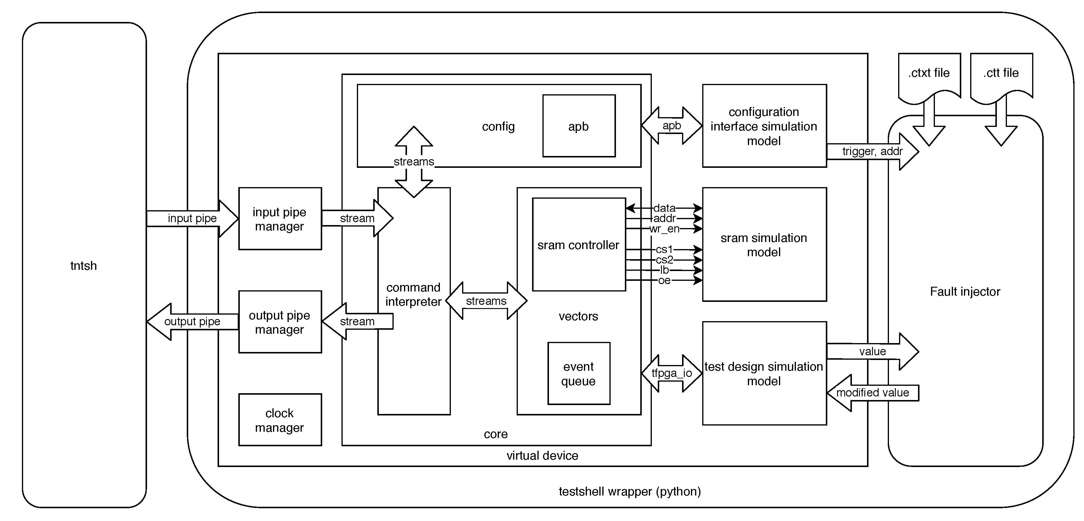
The virtual device (also shortened as vdev) is a VHDL model of the firmware architecture for an FPGA-based fault injection platform known as FTU-VEGAS. This platform is developed by Universidad de Sevilla through the European H2020 project VEGAS, (Validation of high capacity rad-hard FPGA and software tools). The system has two FPGAs, one to perform the injections, manage the command set, and compare faulty outputs with the golden outputs (outputs without injections), and another FPGA which hosts the Design Under Test (DUT). The software part of the system is named tntsh (Test aNalysis Tools shell). This software operates the hardware by sending the necessary commands and data to perform the injection campaigns, and also receives and stores the results. The architecture for the vdev proposed is the one shown in Figure 1. The vdev communicates with the same software (tntsh) used for the physical hardware through a pair of pipes. The virtual device follows a modular architecture where each module communicates with another through a pair of streams. The functionality and architecture of each module are presented in the following subsections, starting from the top level.
2.1. Top Level Module
This is the top level of the virtual device. This module receives the commands from tntsh and returns the requested data to it through a pair of input/output pipes.
2.2. SRAM Simulation Model
This is a model for the R1WV6416R SRAM device from RENESAS, used to store the input/output vectors of a fault injection campaign in an internal format called wave. The wave contains the bit array that contains the concatenated inputs for the DUT each clock cycle, and the corresponding bit array with the concatenated outputs, and is stored in the SRAM using a simple compression schema.
2.3. Test Design Simulation Model
Instances the design under test.
2.4. Core Module
This module is responsible for accepting instructions from the tntsh software and returning the appropriate values. It instances the command interpreter, which manages the commands received from the software and also interfaces with the vectors and configuration modules. The data interchange between the command interpreter and the rest of the modules is managed by stream modules.
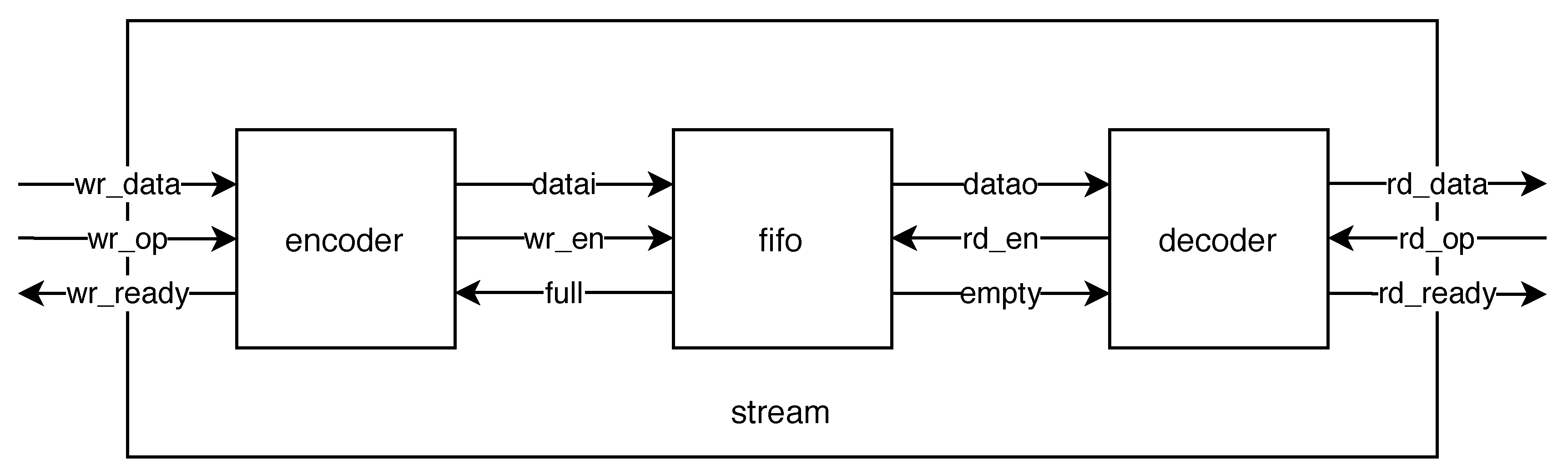
2.5. Stream Module
The stream is the interface used for interchanging data between modules. It is composed of an encoder, a FIFO (First In First Out) memory, and a decoder. Every main module inside the virtual device uses an input stream to request input data and an output stream to provide output data. The stream has been designed to simplify the exchange of multiple data of different widths between modules. Internal data inside the virtual device may have different widths, for example, an injection address may be a 32-bit value but a time value in cycles may be a 64-bit value, while a command always has an 8-bit value. In addition, in order to save SRAM memory space, the width of input and output vectors depends on the characteristics of each design under test. This module needs thus to manage a stream of data of different sizes, with a size between 1 and 8 bytes for each data.
Figure 2 shows the architecture of the stream. The process for module A to send a single multi-byte data to module B is as follows:
- A writes in the stream:
- A waits for the write side of the stream to be ready (wr_ready active). If the write side is not ready, wr_op must be set to zero;
- A sets wr_op to the number of bytes that need to be written (N), while at the same time sets wr_data(N*8-1 downto 0) to the value of the data word to write.
- B reads from the stream:
- B waits for the read side of the stream to be ready (rd_ready active). If the read side is not ready, rd_op must be set to zero;
- B sets rd_op to the number of bytes that need to be read (N);
- Starting from the next clock cycle, when rd_ready is asserted again, rd_data is valid, from which B reads the least significant N bytes.
It must be noted that B can ask for data before A writes anything into the stream, and this will not cause any issue, since the stream will not assert rd_ready until it has enough data, which effectively waits for A to write the requested data.
When bidirectional communications are needed, for example in case of a module sending commands to a submodule and reading the responses to these commands, two streams can be instanced, one for each data direction.
2.6. Config Module
The configuration module is responsible for reading and writing in the simulated target FPGA. It can configure a valid bitstream, and perform I/O operations on individual configuration bits, such as bit flips. It interfaces with a model of the target FPGA (configuration interface simulation model) which interchanges data with the logic of the configuration module using the APB (Advanced Peripheral Bus) protocol.
2.7. Vectors Module
The module is responsible for handling the input and output vectors, both the golden data and the experiment results, as well as handling the emulation clock. It includes the SRAM controller to store and manage the input/output vectors in the SRAM and event queue.
The Event Queue
Every time a special condition is detected during the fault injection (such as discrepancy with golden outputs or end of vectors), an event is raised. When an event is raised, a new item is added to the event queue with each item containing two data: A 1-byte mask of all the events raised and an 8-byte value containing the cycle in which these events were raised.
The event queue allows one to configure flags for the fault injection campaign that can alter the course of the test depending on what happens during the experiment, without continuously communicating with the software. For example, by stopping a run (a complete execution of the test vectors with zero, one or more injections) after detecting damage, without simulating the rest of the clock cycles. The complete event queue can be read by the software after a single run, reducing communication overhead.
2.8. Flow Process and Required Files
The process of injecting faults is made using cocotb [24]. Cocotb is a cosimulation testbench environment written in python. It is an open-source tool which can be used in multiple operating systems. The GHDL open-source simulator is also used to compile the source VHDL code of the vdev to obtain the executable file. Cocotb accesses the values inside the simulation using the simulator’s VPI (Verilog Procedural Interface). A testshell wrapper for the GHDL executable has been written in python so cocotb can be used to access the internal simulation values. With respect to the classification described in Section 1.3.4, we can consider this technique inside the ‘simulator commands’ category.
The tntsh software can be used interactively since it provides a TCL (Tool Command Language) shell, but it can also be used in batch mode by providing .tcl scripts with the commands to execute. Makefiles can be used then to automate the execution of multiple fault injection campaigns, using one or multiple instances of the vdev.
The following files are needed to perform a fault injection campaign:
- pin file:Contains the inputs, outputs, and clock pin signal of the DUT. This file must be written by the user, using a very simple format to indicate signal names, directions, and widths;
- nxb file:The configuration bitstream of the DUT. Generated by the NXmap FPGA vendor tool. While this file is obviously required when using the real hardware, a dummy nxb can be used when injecting faults with the vdev;
- vcd file:A value change dump with the recorded input/output vectors obtained by simulating the design. The user must generate this file using their own testbench with any simulator that supports the generation of VCD files;
- ctxt file:A logic location file that shows the position of the user logic inside the bitstream. Generated by the NXmap tool. This file can also be substituted for a dummy file when using the vdev, removing the need for the proprietary NXmap tool;
- ctt file:This file relates the register names inside the ctxt file with the hierarchical signal names inside the vdev. This file is generated semi-automatically by processing the ctxt file;
- test.tcl:A tcl script with the commands to be executed to perform a fault injection. It loads the configuration, the vectors, and the location files and selects the options desired to perform the campaign. These are the same commands that are supported by the real hardware. The tcl file is not strictly necessary, since the commands can be entered interactively in the tntsh shell.
It must be noted that the nxb and ctxt files are equivalent to bitstream and logic location files generated by software from other vendors, such as Xilinx. The specific nxb and ctxt files are used here so both the software and virtual device remain compatible with the hardware of the fault injection platform, but other file formats could be supported.
The tntsh and virtual device support multiple injection campaign options that can be selected to customize the fault injection experiments. The injector function and injection mask can be also selected. These options are listed below:
- Campaign options:
- -
- check_residual_damage:Checks for damage in the output vectors, during the cycles before injection, for every run;
- -
- damage_per_run:Maximum number of output damages logged per run;
- -
- drop_on_damage:Stop runs after damage_per_run damages;
- -
- export_io:Read the complete faulty vectors, in wave format, after each run;
- -
- unflip_after_run:Attempts to fix the damage to the emulated circuit by unflipping the bits associated with the registers that are changed, at the end of the run;
- -
- blocking:Run campaigns on the foreground, instead of as a background process;
- -
- workdir:Log campaigns in a custom path.
- Injectors:
- -
- inj_gauss:The number of injections is determined randomly according to the normal distribution;
- -
- inj_binomial:The number of injections is determined randomly according to the binomial distribution;
- -
- inj_poisson:The number of injections is determined randomly according to the Poisson distribution;
- -
- inj_exhaustive:This injector will generate one injection per run in every possible combination of the target cycle and register lists, then interrupt the campaign;
- -
- inj_file:This injector reads its injections from a string formatted as a csv file;
- -
- inj_cleanAn injector that generates empty injection lists.
- Injection Masks:The injection masks eliminate injections from the ones generated by the injector according to some criteria.
- -
- mask_bernoulli:Set up a mask that discards injections with a threshold probability.;
- -
- mask_none:Unset current injection mask, and all injections will be used during the campaign.
2.9. Technical Requirements for the Virtual Device
While there are no specific hardware requirements for the use of the virtual device, it needs the following software:
- The GHDL simulator, which is available both for Linux and Microsoft Windows;
- A mechanism to create unix pipes or pipes that behave as such;
- The tntsh software, which in turn requires a C compiler that supports the C++17 revision of the standard for the C++ programming language (such as gcc or clang), and some libraries readily available in most modern GNU/Linux systems;
- The cocotb coroutine simulation framework, which in turn requires python 3.
The experimental results for this paper have been obtained in an Acer EX2540 series computer, model NX.EFHEB.2002, with 8 GB of RAM and an Intel Core i5 7200U processor, running the Debian GNU/Linux Operating System, version 10.
3. Experimental Results
A number of DUTs of increasing complexity have been chosen to perform fault injection with the vdev. The selected designs are described below:
- counter:Implements an 8-bit counter;
- adder acum:This design accumulates the value of an 8-bit input vector in a 20-bit vector;
- shiftreg:Implements an 8-bit shift register;
- b13:An interface to meteo sensors [25];
- FIFO:A simple 32-bit FIFO memory [26];
- pcm:An Integrated Interchip Sound (IIS) interface for the PCM3168 codec [27].
For each DUT, a campaign using a gaussian injector and no injection masks was performed. The gaussian injector was configured with and , so a single SEU was injected each run. Each campaign performed a total of 1000 injections among the list of candidates, which may or may not have propagated to the primary outputs, causing output damage. For each design, the Architectural Vulnerability Factor (AVF), which is the percentage of damages obtained over the total of injections performed [28], was calculated and is presented in Table 1, Table 2, Table 3, Table 4, Table 5 and Table 6. Note that registers that do not produce output errors when injected are not shown in the tables, but are included in the global AVF calculations of the design. Sometimes designs can break when adapting them to a fault injection platform if the process is not made with special care. To check the correct functionality of the designs before performing a campaign, an emuvssim test was performed for each design. Emuvssim tests check the emulation in the virtual device and simulation with a test bench given by the user match, by comparing both waveforms. This allows one to prove that the virtual device does not break functionality and also helps to verify the firmware/software of the fault injection platform. All designs passed the emuvvsim tests.
3.1. Campaign Execution Times
To save execution time, multiple instances of the virtual device can be launched in parallel. The maximum number of instances depends on the processor capacity of the user thus allowing a faster performance than when using proprietary tools, if enough processing capability is available.
Table 7 shows the percentage of execution speed improvement when using two, four, and eight devices:
3.2. Discussion
The main disadvantage of the proposed approach is that it is slower than FPGA-based fault injection. Conversely, one of its advantages is that it does not require any hardware devices.
An advantage that can mitigate the previous disadvantage of this approach is that the fault injection campaigns can be parallelized by instantiating multiple virtual devices, up to the available computing capacity. By using open source tools, this approach does not have any arbitrary license-based limitations to the number of devices that can be executed at the same time.
Another advantage of the approach is the compatibility with the same software that is used with the real hardware. The cost of having this compatibility is the increase of complexity in the virtual device.
The current version of the virtual device requires recompiling the VHDL source when new designs are added. In order to make the device available to more users and simplify the design preparation, it would be a good idea to separate the two elements. For example, an object file for the virtual device could be provided that the user could link to the object files of their design under test.
Another issue to consider is that special care must be taken in the timing of the forcing and release actions of the signal where the fault is being injected. If the signal force is released before the active clock cycle of the design under test, it is possible that the fault is erased and not captured by the design. However, if the signal force is released after the active clock cycle of the design under test, there is the risk that the fault does not correctly propagate (for example, in case of the fault crossing some logic cones and propagating to the input of the same flip-flop) or that it remains for more time than is needed, which would result in an incorrect SEU model. This was solved by using the trigger methods provided by cocotb to synchronize with respect to the clock signal for the design under test.
A current limitation of this approach is that the latest version of cocotb (1.5.dev0) cannot access signals inside a record with the latest version of GHDL (1.0-dev/v0.37.0), which may impact the fault coverage of complex designs that use these datatypes. This is a known limitation of the simulator and is currently an open issue in the GHDL issue tracker, so it can be expected to be fixed in the future. A possible workaround until this limitation is removed, is to inject the faults in a post-synthesis version of the design under test. To achieve this, the synthesis of the design under test must be performed, and afterwards a netlist of the synthesized design must be generated in VHDL format. For example, the netgen tool from Xilinx allows to do this.
4. Conclusions and Future Work
A virtual device to perform fault injection by simulation was designed, developed, and demonstrated. This virtual device is also a model of the FTU-VEGAS fault injector by emulation firmware, extended with fault injection capabilities, and is fully compatible with the software that communicates with real hardware. A set of injection campaigns with increasing complexity was performed and the results of the Architectural Vulnerability Factor for these campaigns were exposed. The virtual device demonstrated to not disturb the correct functionality of the test designs in the absence of injected faults, with the emulation versus simulation tests. The virtual device can be fully compiled and used with only free and open source software, avoiding the use of expensive proprietary simulators, and campaign speed can be parallelized by running multiple instances of the virtual device without any restrictions, which helps to bridge the speed gap with respect to FPGA-based solutions, when running the tests in powerful servers with multiple processor cores.
Future work will include comparing the results obtained with the virtual device with the results obtained using real hardware when it becomes available and decoupling the HDL compilation of the virtual device and the DUTs, so binaries of the virtual device can be distributed and linked to or co-simulated with a third party’s confidential designs.
Author Contributions
Conceptualization, H.G.-M.; Methodology, H.G.-M. and M.M.-Q.; Validation and bug fixing: M.M.-Q., L.S. and H.G.-M.; Software, L.S.; Simulation, M.M.-Q.; Fault injection, M.M.-Q.; Analysis, M.M.-Q. and H.G.-M.; Investigation, M.M.-Q. and H.G.-M.; Writing—original draft preparation, M.M.-Q. and H.G.-M.; Writing—review and editing, H.G.-M. and M.M.-Q.; Supervision, H.G.-M.; Project administration, H.G.-M. All authors have read and agreed to the published version of the manuscript.
Funding
This work was supported by the European Commission, through the project “VEGAS: Validation of European high capacity rad-hard FPGA and software tools”, project ID 687220.
Acknowledgments
The authors would like to thank the authors and maintainers of the free and open source tools used in this paper: Tristan Gingold and the rest of GHDL contributors, Potential Ventures, and the rest of cocotb developers and maintainers (especially Luke Darnell for adding the signal force and release capabilities and Stefan Biereigel for porting them to the latest master version of cocotb), the GNU project, and the Python software foundation. The authors also want to thank NanoXplore for providing a version of the NXmap software.
Conflicts of Interest
The authors declare no conflict of interest.
Abbreviations
The following abbreviations are used in this manuscript:
| APB | Advanced Peripheral Bus |
| AVF | Architectural Vulnerability Factor |
| BRAM | Block Random Access Memory |
| COTS | Commercial Off-The-Shelf |
| CPU | Central Processing Unit |
| DUT | Device Under Test |
| FIFO | First In First Out |
| FPGA | Field Programmable Gate Array |
| FSM | Finite State Machine |
| FT-Unshades | Fault Tolerance - Universidad de Sevilla Hardware Debugging System |
| FTU-VEGAS | FT-Unshades for the Validation of European high capacity rad-hard FPGA and Software tools |
| FW | Firmware |
| HDL | Hardware Description Language |
| HW | Hardware |
| IP | Intellectual Property |
| OS | Operating System |
| SEB | Single Event Burnout |
| SEE | Single Event Effect |
| SEL | Single Event Latchup |
| SET | Single Event Transient |
| SEU | Single Event Upset |
| SRAM | Static Random Access Memory |
| SW | Software |
| VCD | Value Change Dump |
| VDEV | Virtual DEVice |
| VHDL | Very High Speed Integrated Circuit Hardware Description Language |
References
- Duzellier, S. Radiation effects on electronic devices in space, Radiation effects on electronic devices in space. Aerosp. Sci. Technol. 2005, 9, 93–99. [Google Scholar] [CrossRef]
- Dodd, P.E.; Massengill, L.W. Basic mechanisms and modeling of single-event upset in digital microelectronics. IEEE Trans. Nucl. Sci. 2003, 50, 583–602. [Google Scholar] [CrossRef]
- Bedi, R. First Design-In Experiences of Xilinx’s, 20 nm, Kintex Ultrascale KU060 for Space Applications and 16 nm UltraScale+ RFSoC for Ground Segment. In 2018 SpacE FPGA Users Workshop, 4th ed.; European Space Research and Technology Centre (ESTEC), European Space Agency (ESA): Noordwijk, The Netherlands, 2018. [Google Scholar]
- Michel, H.; Guzmán-Miranda, H.; Dörflinger, A.; Michalik, H.; Echanove, M.A. SEU fault classification by fault injection for an FPGA in the space instrument SOPHI. In Proceedings of the 2017 NASA/ESA Conference on Adaptive Hardware and Systems (AHS), Pasadena, CA, USA, 24–27 July 2017; pp. 9–15. [Google Scholar]
- Larchev, G.V.; Lohn, J.D. Evolutionary based techniques for fault tolerant field programmable gate arrays. In Proceedings of the 2nd IEEE International Conference on Space Mission Challenges for Information Technology (SMC-IT’06), Pasadena, CA, USA, 17–20 July 2006. [Google Scholar]
- Muñoz-Quijada, M.; Sanchez-Barea, S.; Vela-Calderon, D.; Guzman-Miranda, H. Fine-Grain Circuit Hardening Through VHDL Datatype Substitution. Electronics 2019, 8, 24. [Google Scholar] [CrossRef] [Green Version]
- Kastensmidt, F.L.; Carro, L.; Reis, R. Fault-Tolerance Techniques for SRAM-Based FPGAs; Springer: Boston, MA, USA, 2006. [Google Scholar]
- ECSS Secretariat, ESA-ESTEC, Requirements & Standards Division, “ECSS-Q-HB-60-02A: Space product assurance. Techniques for Radiation Effects Mitigation in ASICs and FPGAs Handbook”; ESA Requirements and Standards Division, Noordwijk, The Netherlands. 2016. Available online: https://escies.org/download/webDocumentFile?id=64426 (accessed on 23 October 2020).
- Ziade, H.; Ayoubi, R.A.; Velazco, R. A Survey on Fault Injection Techniques. Int. Arab J. Inf. Technol. 2004, 1, 171–186. [Google Scholar]
- Courbon, F.; Fournier, J.J.; Loubet-Moundi, P.; Tria, A. Combining Image Processing and Laser Fault Injections for Characterizing a Hardware AES. IEEE Trans. Comput. Aided Des. Integr. Circuits Syst. 2015, 34, 928–936. [Google Scholar] [CrossRef]
- Arlat, J.; Crouzet, Y.; Laprie, J.C. Fault injection for dependability validation of fault-tolerant computing systems. In Proceedings of the 19th International Symposium on Fault-Tolerant Computing, Digest of Papers, Chicago, IL, USA, 21–23 June 1989; pp. 348–355. [Google Scholar]
- Mansour, W.; Velazco, R.; El Falou, W.; Ziade, H.; Ayoubi, R. SEU simulation by fault injection in PSoC device: Preliminary results. In Proceedings of the 2012 2nd International Conference on Advances in Computational Tools for Engineering Applications (ACTEA), Beirut, Lebanon, 12–15 December 2012; pp. 330–333. [Google Scholar]
- Da Silva, A.; Gonzalez-Calero, A.; Martinez, J.F.; Lopez, L.; Garcia, A.B.; Hernández, V. Design and Implementation of a Java Fault Injector for Exhaustif® SWIFI Tool. In Proceedings of the 2009 Fourth International Conference on Dependability of Computer Systems, Brunow, Poland, 30 June–2 July 2009; pp. 77–83. [Google Scholar]
- Civera, P.; Macchiarulo, L.; Rebaudengo, M.; Reorda, M.S.; Violante, M. Exploiting circuit emulation for fast hardness evaluation. IEEE Trans. Nucl. Sci. 2001, 48, 2210–2216. [Google Scholar] [CrossRef]
- Aguirre, M.A.; Tombs, J.N.; Torralba, A.; Franquelo, L.G. UNSHADES-1: An advanced tool for In-System Run-Time Hardware Debugging. In Proceedings of the Field Programmable Logic and Applications, Lisbon, Portugal, 1–3 September 2003; pp. 1170–1173. [Google Scholar]
- Mogollon, J.M.; Guzman-Miranda, H.; Napoles, J.; Barrientos, J.; Aguirre, M.A. FTUNSHADES2: A novel platform for early evaluation of robustness against SEE. In Proceedings of the 2011 12th European Conference on Radiation and Its Effects on Components and Systems, Sevilla, Spain, 19–23 September 2011; pp. 169–174. [Google Scholar]
- Intel. Fault Injection Intel FPGA IP Core User Guide. Available online: https://www.intel.com/content/dam/www/programmable/us/en/pdfs/literature/ug/ug_fault_injection.pdf (accessed on 19 October 2020).
- Xilinx. Soft Error Mitigation (SEM) Core. Available online: https://www.xilinx.com/products/intellectual-property/sem.html (accessed on 19 October 2020).
- Mohammadi, A.; Ebrahimi, M.; Ejlali, A.; Miremadi, S.G. SCFIT: A FPGA-based fault injection technique for SEU fault model. In Proceedings of the 2012 Design, Automation & Test in Europe Conference & Exhibition (DATE), Dresden, Germany, 12–16 March 2012; pp. 586–589. [Google Scholar]
- Baraza, J.C.; Gracia, J.; Gil, D.; Gil, P.J. A prototype of a VHDL-based fault injection tool: Description and application. J. Syst. Archit. 2002, 47, 847–867. [Google Scholar] [CrossRef]
- Baraza, J.C.; Gracia, J.; Gil, D.; Gil, P.J. VHDL Simulation-Based Fault Injection Techniques. In Fault Injection Techniques and Tools for Embedded Systems Reliability Evaluation; Benso, A., Prinetto, P., Eds.; Frontiers in Electronic Testing; Springer: Boston, MA, USA, 2002; Volume 23. [Google Scholar]
- Sutherland, S. The Verilog PLI Handbook: A User’s Guide and Comprehensive Reference on the Verilog Programming Language Interface; The International Series in Engineering and Computer Science; Springer: Boston, MA, USA, 2002; Volume 666. [Google Scholar]
- Guthoff, J.; Sieh, V. Combining software-implemented and simulation-based fault injection into a single fault injection method. In Proceedings of the 25th International Symposium on Fault-Tolerant Computing, Digest of Papers, Pasadena, CA, USA, 27–30 June 1995. [Google Scholar]
- Various. Cocotb Documentation. Available online: https://docs.cocotb.org/en/stable/ (accessed on 19 October 2020).
- Corno, F.; Reorda, M.S.; Squillero, G. RT-level ITC’99 benchmarks and first ATPG results. IEEE Des. Test Comput. 2000, 17, 44–53. [Google Scholar] [CrossRef]
- VHDL Standard FIFO. Available online: http://www.deathbylogic.com/2013/07/vhdl-standard-fifo/ (accessed on 19 October 2020).
- I2S Interface Designed for the PCM3168 Audio Interface from Texas Instruments. Available online: https://github.com/wklimann/PCM3168 (accessed on 19 October 2020).
- Mukherjee, S.S.; Weaver, C.T.; Emer, J.; Reinhardt, S.K.; Austin, T. Measuring architectural vulnerability factors. IEEE Micro 2003, 23, 70–75. [Google Scholar] [CrossRef]
Figure 1.
Firmware architecture of the virtual device and communication with tntsh.

Figure 2.
Stream module. For simplicity, global clock and reset connections are not shown. A dual-clock fifo may be used to decouple clock domains and in that case, the encoder should use the same clock as the write side of the fifo, and the decoder should use the same clock as the read side of the fifo.


Table 1.
Campaign for counter design.
| Design: Counter | |||||
|---|---|---|---|---|---|
| reg_name | bits | damages_per_reg | injections_without_damage | injections_per_reg | avf (%) |
| add_L26_stage1:SUM1 | 1 | 120 | 0 | 120 | 100 |
| add_L26_stage1:SUM2 | 1 | 121 | 4 | 125 | 96.8 |
| add_L26_stage1:SUM3 | 1 | 117 | 2 | 119 | 98.3 |
| add_L26_stage1:SUM4 | 1 | 127 | 3 | 130 | 97.7 |
| add_L26_stage2:SUM1 | 1 | 148 | 2 | 150 | 98.7 |
| add_L26_stage2:SUM2 | 1 | 118 | 4 | 122 | 96.7 |
| add_L26_stage2:SUM3 | 1 | 95 | 0 | 95 | 100 |
| add_L26_stage2:SUM4 | 1 | 139 | 0 | 139 | 100 |
| TOTAL | 8 | 985 | 15 | 1000 | 98.5 |
Table 2.
Campaign for adder_acum design.
| Design: Adderacum | |||||
|---|---|---|---|---|---|
| reg_name | bits | damages_per_reg | injections_without_damage | injections_per_reg | avf (%) |
| add_L23_stage1:SUM1 | 1 | 39 | 3 | 42 | 92.9 |
| add_L23_stage1:SUM2 | 1 | 43 | 2 | 45 | 95.5 |
| add_L23_stage1:SUM3 | 1 | 51 | 1 | 52 | 98 |
| add_L23_stage1:SUM4 | 1 | 36 | 0 | 36 | 100 |
| add_L23_stage2:SUM1 | 1 | 44 | 0 | 44 | 100 |
| add_L23_stage2:SUM2 | 1 | 42 | 2 | 44 | 95.5 |
| add_L23_stage2:SUM3 | 1 | 46 | 3 | 49 | 93.9 |
| add_L23_stage2:SUM4 | 1 | 60 | 4 | 64 | 93.8 |
| add_L23_stage3:SUM1 | 1 | 41 | 5 | 46 | 89.1 |
| add_L23_stage3:SUM2 | 1 | 39 | 1 | 40 | 97.5 |
| add_L23_stage3:SUM3 | 1 | 50 | 1 | 51 | 98 |
| add_L23_stage3:SUM4 | 1 | 47 | 2 | 49 | 95.9 |
| add_L23_stage4:SUM1 | 1 | 38 | 1 | 39 | 97.4 |
| add_L23_stage4:SUM2 | 1 | 47 | 2 | 49 | 95.9 |
| add_L23_stage4:SUM3 | 1 | 58 | 4 | 62 | 93.5 |
| add_L23_stage4:SUM4 | 1 | 48 | 0 | 48 | 100 |
| add_L23_stage5:SUM1 | 1 | 36 | 3 | 39 | 92.3 |
| add_L23_stage5:SUM2 | 1 | 58 | 1 | 59 | 98.3 |
| add_L23_stage5:SUM3 | 1 | 45 | 3 | 48 | 93.8 |
| add_L23_stage5:SUM4 | 1 | 37 | 2 | 39 | 94.9 |
| TOTAL | 21 | 95 | 905 | 1000 | 90.5 |
Table 3.
Campaign for shiftreg design.
| Design: Shiftreg | |||||
|---|---|---|---|---|---|
| reg_name | bits | damages_per_reg | injections_without_damage | injections_per_reg | avf (%) |
| reg_reg | 8 | 100 | 900 | 1000 | 10 |
| TOTAL | 8 | 100 | 900 | 1000 | 10 |
Table 4.
Campaign for B13 design.
| Design: B13 | |||||
|---|---|---|---|---|---|
| reg_name | bits | damages_per_reg | injections_without_damage | injections_per_reg | avf (%) |
| rdy_reg | 1 | 22 | 4 | 26 | 84.6 |
| send_en_reg | 1 | 17 | 4 | 21 | 80.9 |
| tre_reg | 1 | 1 | 16 | 17 | 5.9 |
| TOTAL | 49 | 40 | 960 | 1000 | 4.0 |
Table 5.
Campaign for FIFO (First In First Out) design.
| Design: FIFO | |||||
|---|---|---|---|---|---|
| reg_name | bits | damages_per_reg | injections_without_damage | injections_per_reg | avf (%) |
| empty_reg | 1 | 12 | 39 | 51 | 23.5 |
| head_reg | 8 | 91 | 328 | 419 | 21.7 |
| looped_reg | 1 | 8 | 44 | 52 | 15.4 |
| tail_reg | 8 | 104 | 337 | 441 | 23.6 |
| full_reg | 1 | 12 | 25 | 37 | 32.4 |
| TOTAL | 19 | 227 | 773 | 1000 | 22.7 |
Table 6.
Campaign for pcm3168 design.
| Design: pcm3168 | |||||
|---|---|---|---|---|---|
| reg_name | bits | damages_per_reg | injections_without_damage | injections_per_reg | avf (%) |
| I2S_IN_1|DATA_L_reg | 23 | 176 | 152 | 328 | 53.7 |
| I2S_IN_1|s_current_lr_reg | 1 | 2 | 12 | 14 | 14.3 |
| I2S_IN_1|shift_reg_reg | 23 | 110 | 212 | 322 | 34.1 |
| TOTAL | 74 | 288 | 712 | 1000 | 28.8 |
Table 7.
Execution time improvement.
| Design | 2 Devices (%) | 4 Devices (%) | 8 Devices (%) |
|---|---|---|---|
| counter | 40.83 | 64.20 | 74.35 |
| adder_acum | 45.71 | 62.64 | 71.81 |
| dualcounter | 42.48 | 65.08 | 73.77 |
| shiftreg | 42.98 | 67.27 | 76.83 |
| b13 | 49.10 | 66.42 | 77.64 |
| fifo | 47.53 | 67.69 | 76.12 |
| pcm | 48.48 | 67.50 | 77.40 |
Publisher’s Note: MDPI stays neutral with regard to jurisdictional claims in published maps and institutional affiliations. |
© 2020 by the authors. Licensee MDPI, Basel, Switzerland. This article is an open access article distributed under the terms and conditions of the Creative Commons Attribution (CC BY) license (http://creativecommons.org/licenses/by/4.0/).
Share and Cite
MDPI and ACS Style
Muñoz-Quijada, M.; Sanz, L.; Guzman-Miranda, H. A Virtual Device for Simulation-Based Fault Injection. Electronics 2020, 9, 1989. https://doi.org/10.3390/electronics9121989
AMA Style
Muñoz-Quijada M, Sanz L, Guzman-Miranda H. A Virtual Device for Simulation-Based Fault Injection. Electronics. 2020; 9(12):1989. https://doi.org/10.3390/electronics9121989
Chicago/Turabian StyleMuñoz-Quijada, Maria, Luis Sanz, and Hipolito Guzman-Miranda. 2020. "A Virtual Device for Simulation-Based Fault Injection" Electronics 9, no. 12: 1989. https://doi.org/10.3390/electronics9121989
Note that from the first issue of 2016, this journal uses article numbers instead of page numbers. See further details here.