A Low-Cost Current Sensor Based on Semi-Cylindrical Magnetostrictive Composite
by

Shaoyi Xu
1,2, 
Qiang Peng
1,
Fangfang Xing
3,
Hongyu Xue
1,
Junwen Sun
1,
Lei Ma
4 and
Ming Li
5,* 1
School of Mechatronic Engineering, China University of Mining and Technology, Xuzhou 221116, China
2
Jiangsu Collaborative Innovation Center of Intelligent Mining Equipment, China University of Mining and Technology, Xuzhou 221008, China
3
School of Mechatronic Engineering, Xuzhou College of Industrial Technology, Xuzhou 221116, China
4
School of Management, Shanghai University of Engineering Science, Shanghai 200336, China
5
School of Information and Control Engineering, China University of Mining and Technology, Xuzhou 221116, China
*
Author to whom correspondence should be addressed.
Electronics 2020, 9(11), 1833; https://doi.org/10.3390/electronics9111833
Submission received: 9 October 2020
/
Revised: 28 October 2020
/
Accepted: 30 October 2020
/
Published: 3 November 2020
(This article belongs to the Section Systems & Control Engineering)
Abstract
:This paper presents the design, fabrication, and characterization of a compact current sensor based on magnetostrictive composites and resistance strain gauges. Firstly, we designed three kinds of current sensors with different structures, in which the shape of the giant magnetostrictive material (GMM) was cuboid, cylindrical, and semi-cylindrical. A set of finite element method (FEM) simulations were performed to qualitatively guide the design of three prototypes of the current sensor. It was determined that the most ideal shape of the GMM was semi-cylindrical. Secondly, Terfenol-D (TD) powder and epoxy resin were mixed to prepare magnetostrictive composites. In this paper, magnetostrictive composites with different particle size ranges and mass ratio were prepared and tested. The results show that the magnetostrictive composites had the best performance when the particle size range was 149–500 μm and the mass ratio of epoxy resin to TD powder was 1:5. Finally, this paper tested the performance of the sensor. The sensitivity, repeatability, and linear working range of the sensor reached 0.104 με/A, 2.51%, and 100–900 A respectively, when only 0.31 g of TD powder was employed. This means that current measurement with low cost, high sensitivity, and wide range was realized.
1. Introduction
With the rapid development of the power industry, the current sensor plays a key role in the fields of electric energy measurement, monitoring, and protection [1]. However, the traditional electromagnetic current sensor has weak antielectromagnetic interference ability, difficult insulation, and a small dynamic range, which hinder meeting the monitoring needs of the power system [2,3]. Therefore, researches are looking for a new type of current sensor to meet the needs of online monitoring of power systems and high-precision fault diagnosis.
Giant magnetostrictive materials (GMMs) have the advantages of small size, fast response speed, high precision, and easy integration [4]. Magnetostrictive materials are widely used; for example, a Micro-Electro-Mechanical System (MEMS) magnetoelectric sensor combined with magnetostrictive material and piezoelectric material can not only detect weak magnetic fields, but also be widely used in biological magnetic field detection and magnetic particle imaging [5,6]. Terfenol-D (TD) alloy is a new type of rare earth giant magnetostrictive material. Because of its well-known giant magnetostriction, Terfenol-D, an alloy composed of TbxDy1−xFe2, has been employed for electromagnetic measurement [7,8]. The resistance strain gauge has the advantages of high accuracy, small size, light weight, low cost, stable performance, high reliability, and convenient multipoint measurement. A current sensor combining GMM and a resistance strain gauge has attracted wide attention.
In 2005, Satpathi et al. [9] proposed a current sensor based on magnetostrictive material. The TD mass of the proposed sensor was 40 g. Magnetostrictive materials have unipolar characteristics. In order to avoid the rectified output of the sensor, a direct current (DC) bias coil was introduced into the sensor. At the same time, mechanical devices were added to the sensor to provide the mechanical compression load. It was found that the output of the sensor was nonlinear when the mechanical compression load was low. When the mechanical compression load was high, the linearity of the sensor increased. Although the mechanical device improved the linearity of the sensor, it increased the complexity of the sensor structure. The addition of the DC bias coil caused the sensor to be active.
In 2013, Cremonezi et al. [10] proposed a current sensor for measuring alternating current. The proposed sensor employed a solid, 144 g toroidal core of TD. The stainless-steel compression ring exerted a certain pressure on the magnetostrictive material, which made the relationship between the strain produced by the magnetostrictive material and the applied magnetic field approximate to a quadratic function. At the same time, the linearity of the sensor was better and the measurement error was smaller under the action of preloading stress. The proposed sensor had a fast transient response, but the sensor did not introduce a DC bias device, which led to the frequency doubling of the sensor output.
In 2015, Nazaré and Werneck et al. [11] proposed a new and compact current sensor. The new sensor was composed of a solid rod of TD using 74 g of the alloy, magnetic conductive material, and a permanent magnet. The magnetic conductive material was made of ordinary ferrosilicon, and the permanent magnet was made of NdFeB. The purpose of adding permanent magnets to the magnetic circuit was to provide a certain constant magnetic field, so that the sensor could work in a linear region and obtain a complete alternating current (AC) cycle. The magnetic field acting on magnetostrictive material consisted of an AC magnetic field generated by the wire and a constant magnetic field generated by the permanent magnet. The authors used permanent magnets instead of DC drive coils; thus, the sensor was passive. Although the proposed sensor eliminated the frequency doubling phenomenon of magnetostrictive materials, it still did not solve the disadvantages of the expensive and fragile Terfenol-D alloy.
In 2019, Dante et al. [12] proposed a toroidal current sensor based on magnetostrictive material. The proposed sensor was composed of magnetostrictive material, magnetic conductive material, and a permanent magnet. Steel bars (99.5% Fe, relative permeability 500) were introduced into the magnetic circuit, which not only reduced the mass of TD, but also increased the magnetic flux density per gram of TD. The cost of the proposed sensor was further reduced, and only 2.0 g of Terfenol-D alloy was used. The transient response test showed that there was no obvious delay between the input and output signals of the sensor, which indicated that the sensor was suitable for fault detection.
Wang et al. [13] proposed a sensitivity enhanced current sensor based on magnetostrictive material. When a mechanical compression force was applied, the GMM’s sensitivity to the magnetic field increased significantly. According to this characteristic, a beam was added to the rectangular GMM to bear the applied pressure, thus forming a T-shaped structure. The material of the beam was 304 stainless steel. A T-shaped structure was placed in a copper support structure. A special copper screw was placed at the upper right of the structure, and the beam of the T-shaped structure was pressurized by the screw, so as to achieve the purpose of pressurizing the T-shaped structure. Therefore, the sensitivity-enhanced current sensor was composed of a GMM, fiber Bragg grating (FBG), copper support structure, and screws made of copper. Experiments showed that the sensitivity of the sensor was significantly improved, and the cost of the proposed structure was low.
However, Terfenol-D alloy is hard, brittle, expensive, and difficult to machine. Thus, in order to address these issues, a giant magnetostrictive powder composite (GMPC) of TD powder and epoxy resin was recently proposed for many applications [14,15]. GMPC also has other excellent properties, such as enhanced tensile strength and low eddy current loss. Because of the preloading stress generated during curing, the preload can be reduced or even saved. In addition, the TD mass used in composite materials is small, and the preparation process of composite materials is relatively simple; thus, the cost is low. At the same time, the magnetostriction of magnetostrictive composites can compete with that of the magnetostrictive alloy.
Lopez et al. [16,17] proposed a current sensor based on magnetostrictive composite. The sensor adopted magnetic field concentration technology, which not only reduced the mass of magnetic conductive materials, but also improved the magnetic flux density on magnetostrictive composite materials. When the mass of Terfenol-D alloy was 0.42 g, the proposed sensor could obtain higher sensitivity and reduce the cost of the sensor.
In this paper, a current sensor based on a semi-cylindrical magnetostrictive composite and resistance strain gauge is proposed. This paper mainly includes the following two aspects:
Improvement of sensor structure: in order to improve the sensitivity of the sensor and reduce the cost of the sensor, we designed three kinds of current sensors with different structures.
Improvement of performance of magnetostrictive composites: in order to study the characteristics of magnetostrictive composites, magnetostrictive composites with different TD particle sizes and different proportions of TD powder were manufactured.
2. Design of Sensor
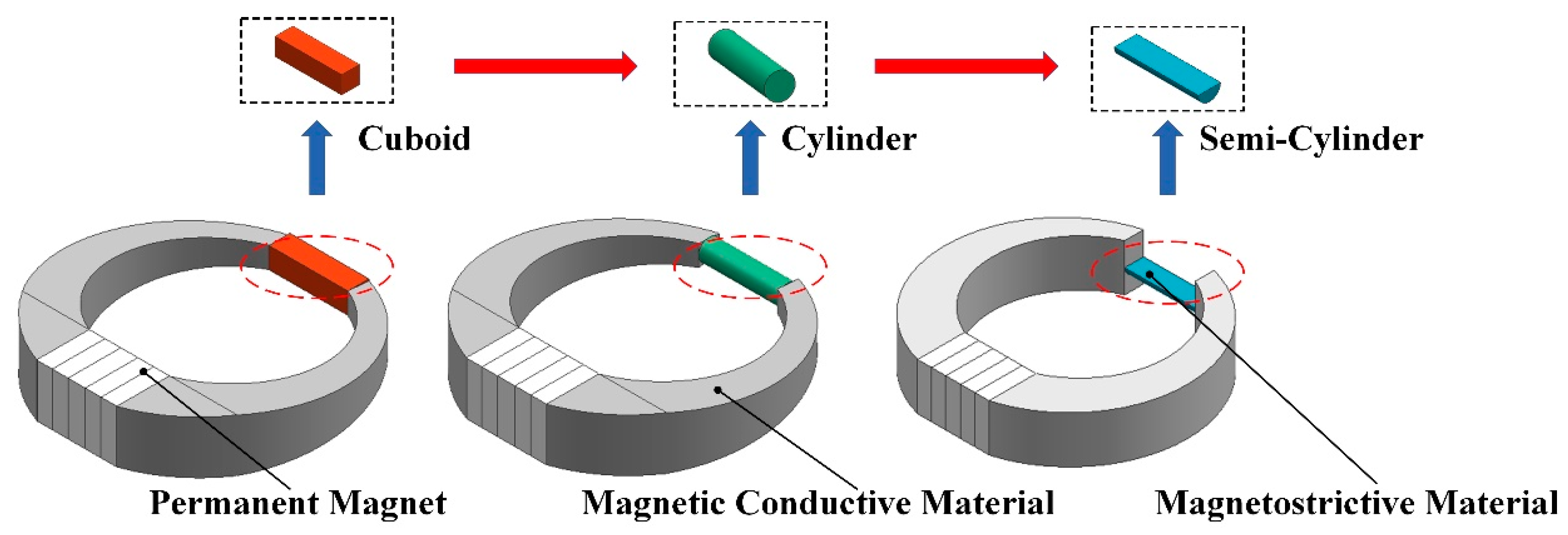
Figure 1 shows the design of the current sensor. The current sensor was composed of magnetostrictive material, magnetic conductive material, and a permanent magnet. The sensor adopted magnetic field concentration technology to improve the magnetic flux density on magnetostrictive composite materials [17]. A permanent magnet was introduced into the magnetic circuit, which allowed the sensor to work in the linear region and obtain a complete AC cycle. We designed three kinds of current sensors with different structures, in which the shapes of the magnetostrictive material were cuboid, cylindrical, and semi-cylindrical.
2.1. Finite Element Simulation
In this paper, we performed FEM simulations to qualitatively guide the design of three prototypes of the current sensor. Firstly, we established three sensor models. The magnetostrictive material in Figure 2a was set to a 4 × 4 × 15 mm3 cuboid. The magnetostrictive material in Figure 2b was set as a cylinder with a diameter of 4 mm and a length of 15 mm. The magnetostrictive material of Figure 2c was set as a semi-cylinder with a diameter of 4 mm and a length of 15 mm. The permanent magnet was set to a 10 × 10 × 3 mm3 cuboid, and the diameter of the conductor was 18 mm. Then, we defined the material properties. The material of the conductor was copper, the relative permeability of the magnetostrictive material was 5, the relative permeability of the magnetic conductive material was 300, and the relative permeability of the permanent magnet was 1.05. Then, we set the boundary conditions. The current of the conductor was set to 400 A. Finally, we meshed the model.
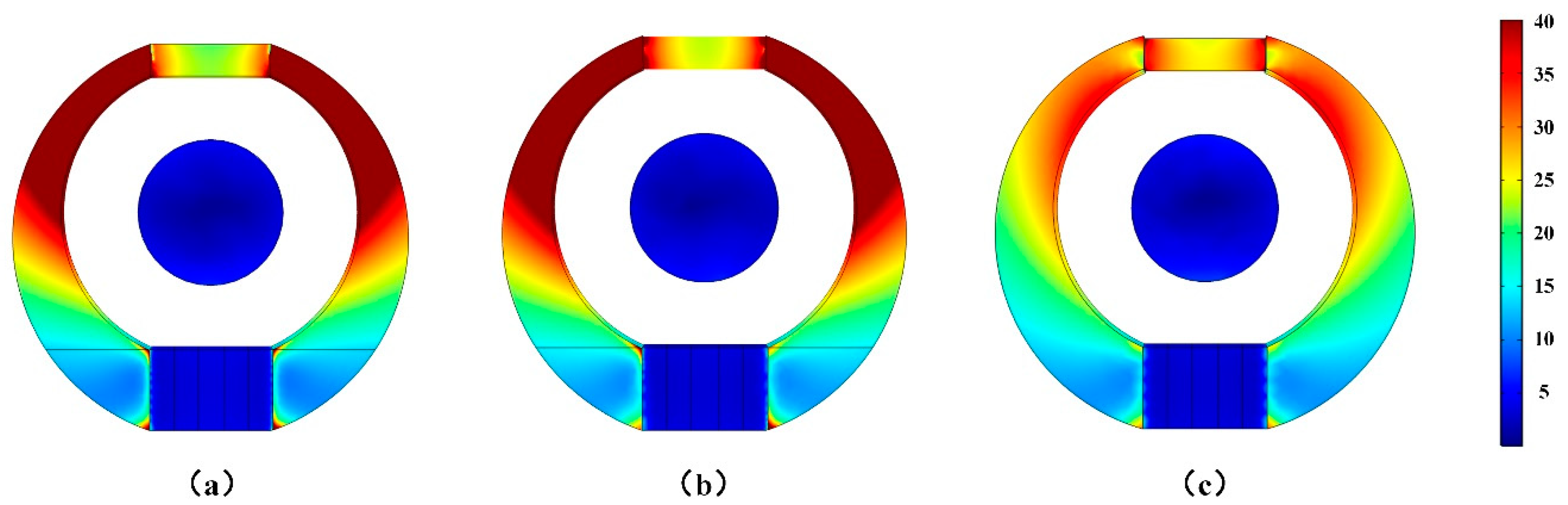
Figure 2 shows the FEM simulation results of the sensor. In the simulations of the magnetic flux density distribution of sensors, red denotes greater magnetic flux density and blue denotes less magnetic flux density. The results show that the magnetic flux density at the position of the magnetostrictive material in Figure 2c was the highest. This means that the sensor based on the semi-cylindrical magnetostrictive material with a diameter of 4 mm and a length of 15 mm not only improved the magnetic flux density, but also reduced the volume of the magnetostrictive material.
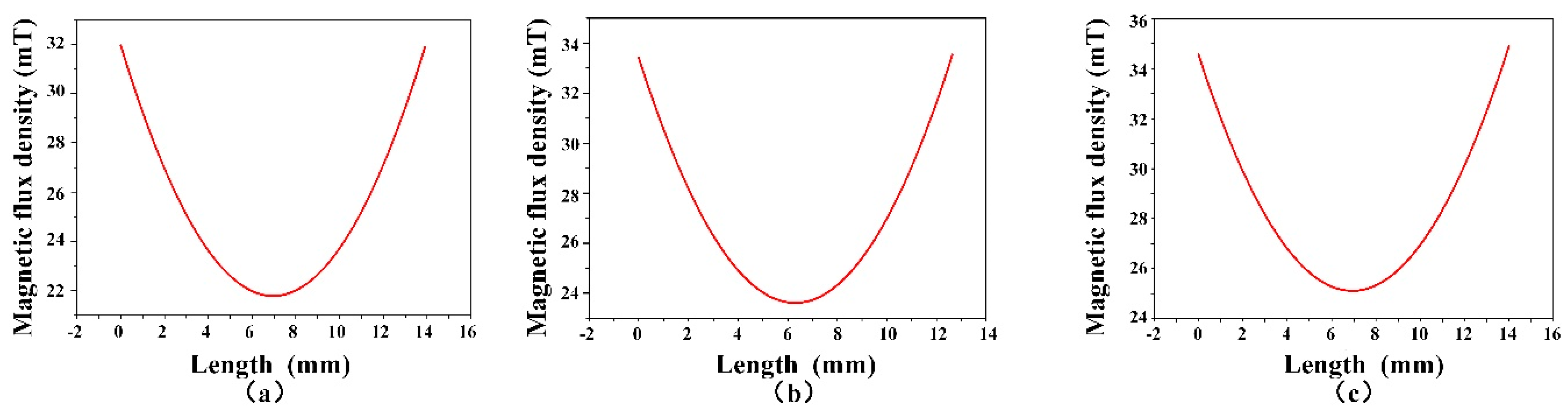
To quantify the magnetic flux density range at the position of the magnetostrictive material, we set the same three-dimensional sectional line for each magnetostrictive material. Figure 3 shows the magnetic flux density range at the position of magnetostrictive materials of sensors with different structures. Then, we summarized the volume and magnetic flux density of magnetostrictive materials of sensors with different structures. As shown in Table 1, compared with the existing sensor based on cuboid magnetostrictive material [17], the sensor based on semi-cylindrical magnetostrictive material not only reduced the volume by more than half, but also increased the maximum magnetic flux density by 9.1% and the minimum magnetic flux density by 15.1%.
When the volume of magnetostrictive material was smaller, the cost of the sensor was lower. When the magnetic flux density at the magnetostrictive material was greater, the sensitivity of the sensor was higher. Therefore, the shape of the magnetostrictive material of the sensor was set as a semi-cylinder. In order to fix all parts together, a three-dimensionally (3D) printed holder was employed.
2.2. Magnetostrictive Composites
Given that Terfenol-D is a hard, brittle alloy, and its use in the form of solid bars and rods is affected by eddy currents, GMPCs were recently explored and successfully employed in current sensors. Thus, the use of GMPCs not only reduces these drawbacks, but also supports decreasing the fragility of the sensor, facilitates its manufacture in different shapes, and allows for a significant reduction in the amount of Terfenol-D employed in the sensor, thereby reducing its cost. Therefore, magnetostrictive composites become the sensitive element of the current sensor. Another key feature of magnetostrictive composites is that the properties of composites depend on the size range and mass fraction of TD particles, which was explored in this paper.
2.3. Manufacture of Sensors
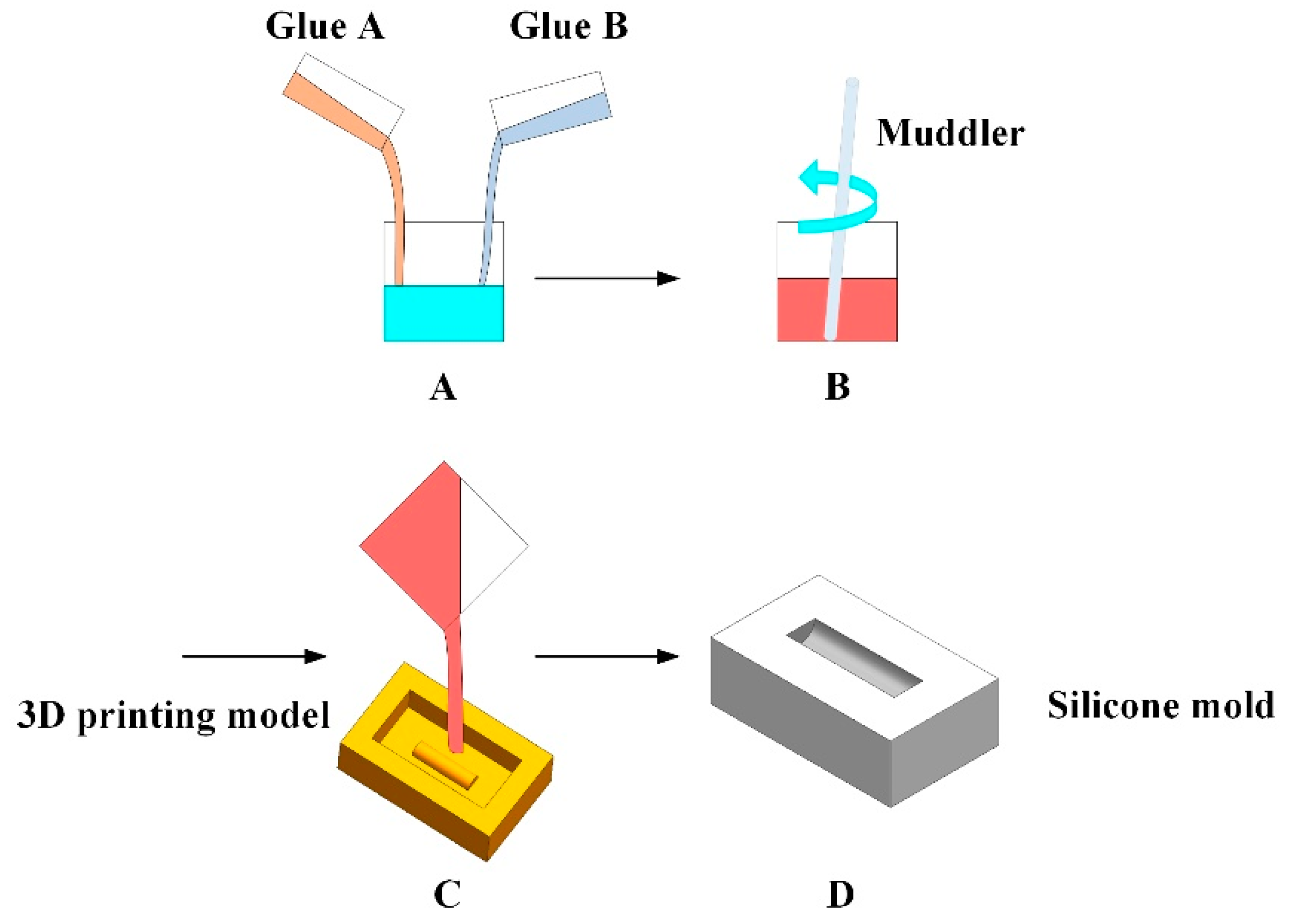
In order to facilitate the demolding of magnetostrictive composites, a silicone mold was prepared in this paper. The manufacturing procedure is shown in Figure 4. First (stage A), glue A and glue B were mixed in a container. The mass ratio of silicone glue A to glue B was 1:1. Next (stage B), the whole mixture was intensively stirred until all the components were homogenized. Subsequently (stage C), after proper stirring, the mixture was poured into a 3D-printed holder. Lastly (stage D), after waiting for a period of time at room temperature, a silicone mold was obtained.
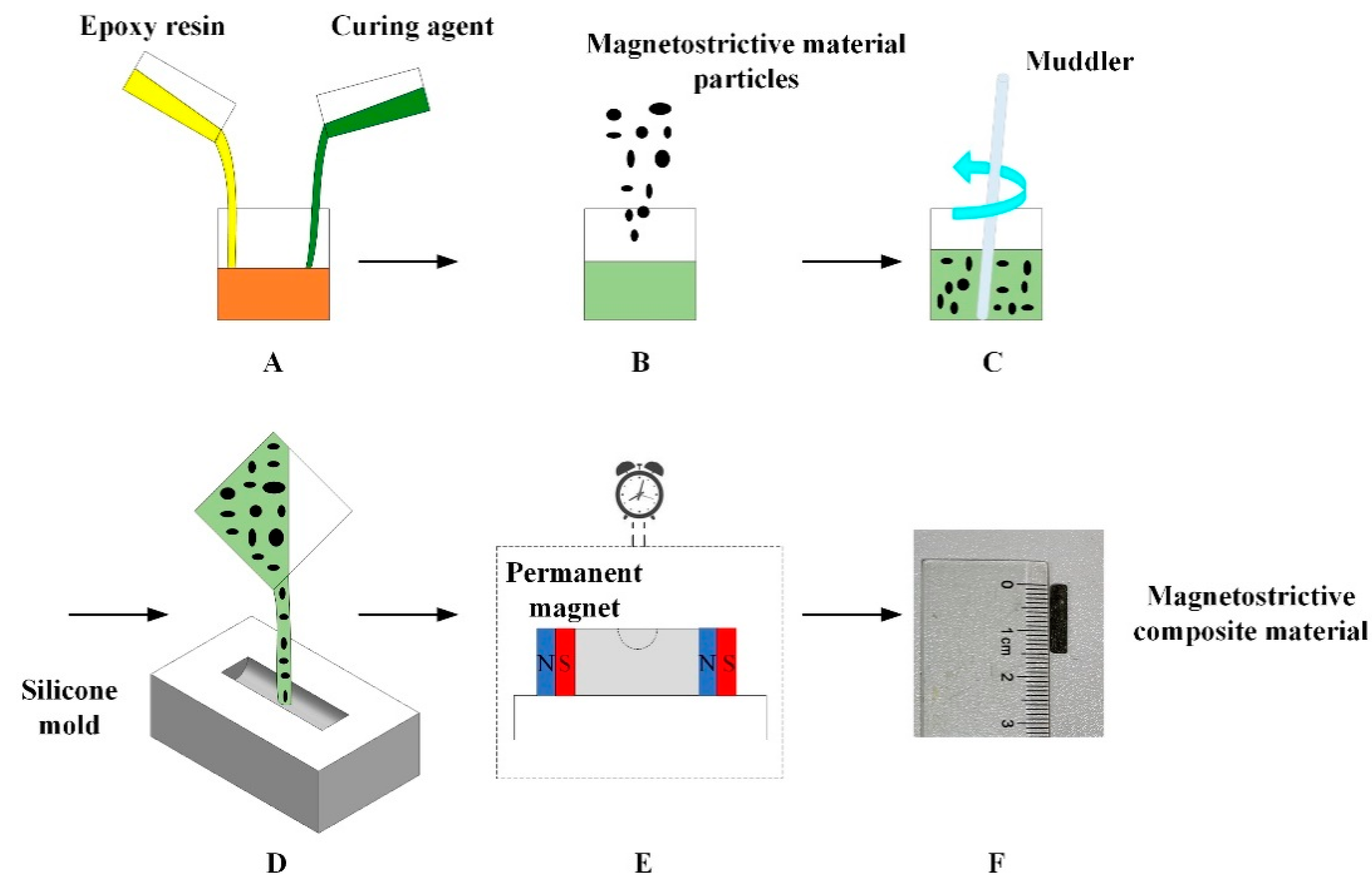
The manufacturing procedure is shown in Figure 5. First (stage A), a measured volume of hardener was added to epoxy resin. The mass ratio of hardener to the resin was 1:3. Next (stage B), to the prepared mixture, a Terfenol-D powder was introduced. Subsequently (stage C), the whole mixture was intensively stirred until all components were homogenized. In the next step (stage D), after proper stirring, the mixture was poured into previously prepared silicone mold. Then (stage E), the silicone mold with the mixture was subjected to polarization. The permanent magnet provided a certain uniform magnetic field to prevent the TD powder from settling in the mixture. Lastly (stage F), after waiting for a period of time at room temperature, the semi-cylindrical magnetostrictive composite with a diameter of 4 mm and a length of 15 mm was obtained.
3. Experimental Results and Discussion
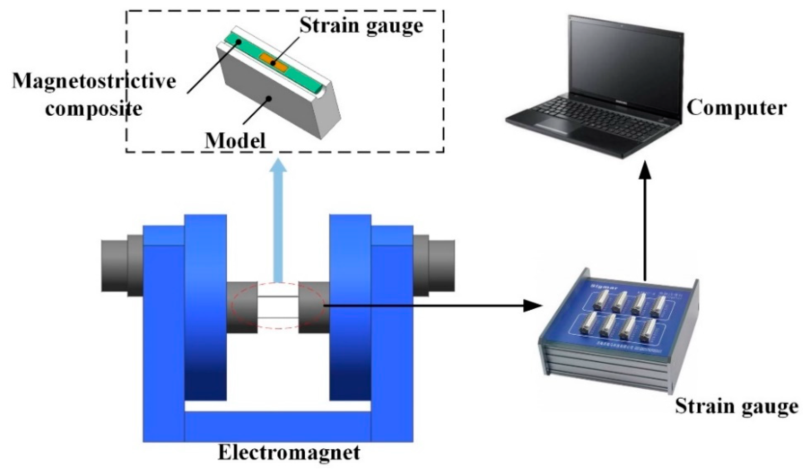
As shown in Figure 6, the test device of the magnetostrictive composite material was composed of an electromagnet, strain gauge, computer, and 3D-printed holder. The uniform and stable parallel magnetic field was generated by the electromagnet. The strain of magnetostrictive composites was measured by the strain gauge. The computer was used to analyze and display the data. The 3D-printed holder was used to support the magnetostrictive composite material and avoid external interference. The main structural parameter of the electromagnet was a working air gap of 0–80 mm, which could be adjusted continuously.
The principle of a resistance strain gauge is to transform the deformation of the magnetostrictive material into a change in resistance, i.e., to indirectly calculate the magnetostrictive strain of magnetostrictive composite by measuring the change in resistance. The resistance strain gauge is attached along the long axis direction of the magnetostrictive composite material (the magnetostrictive direction of the composite material), and the current variation can be obtained by measuring the magnetostrictive variation.
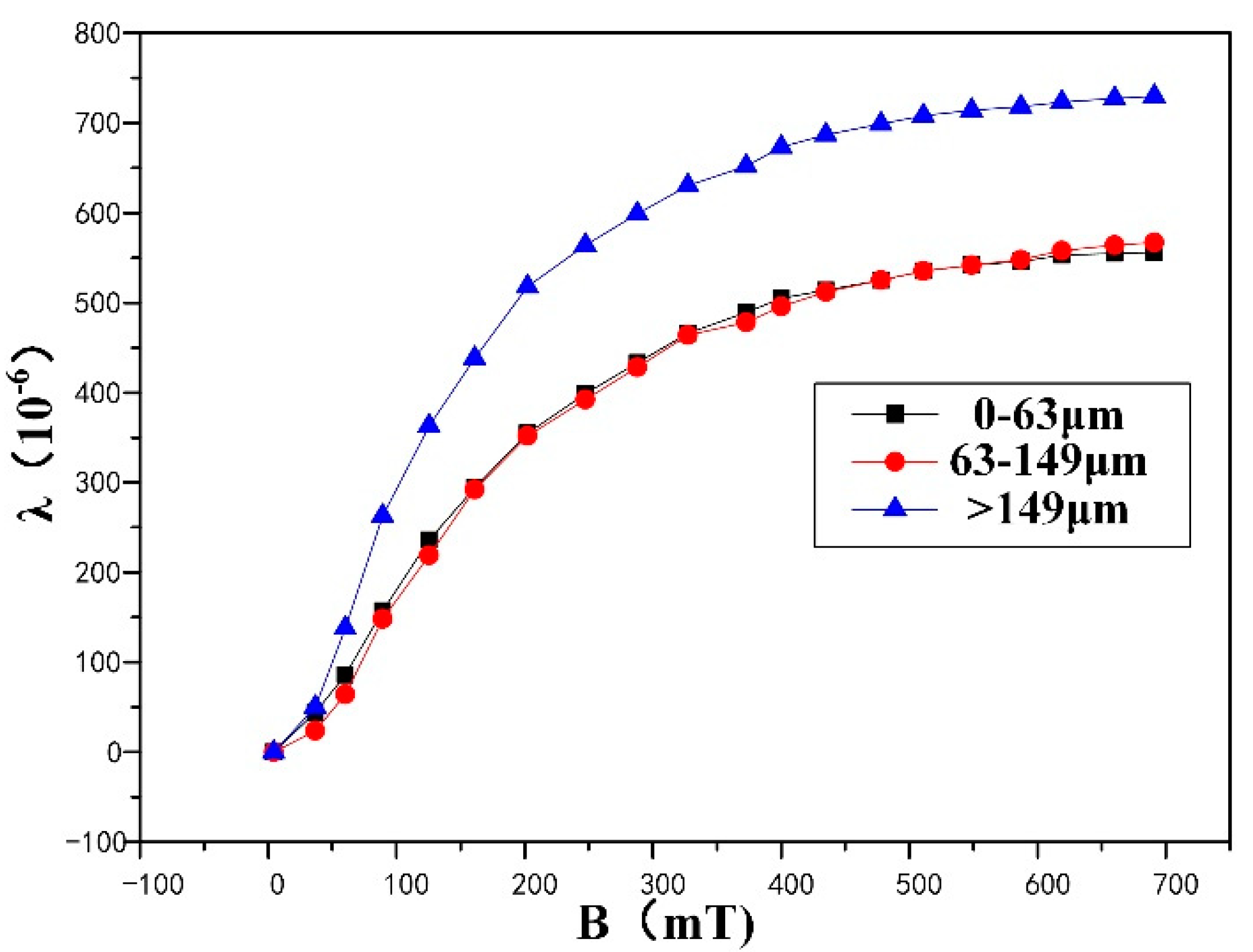
In this paper, the influence of TD particle size on the magnetostrictive composites was studied. The TD alloy was ground into powder under argon protection. Then, the particle size of the powder was divided into 0–63 μm, 63–149 μm, and 149–500 μm groups with a 100-mesh screen and 250-mesh screen. When the proportion of TD powder and shape were the same, magnetostrictive composites with particle sizes of 0–63 m, 63–149 m, and more than 149 m were tested. Figure 7 shows the relationship between magnetostriction coefficient and external magnetic field. It can be seen that the magnetostriction coefficient of magnetostrictive composites was highest when the TD particle size was 149–500 μm. Due to the high surface adsorption of TD particles with a small particle size, clusters would be formed in the mixture; hence, the fluidity and orientation of the particles worsened during the molding of composite materials. When the proportion of particles was the same, there was a larger particle surface area in the composite with a small particle size, which facilitated contact with air and led to oxidation. Therefore, the TD particle size should be 149–500 μm when preparing magnetostrictive composites.
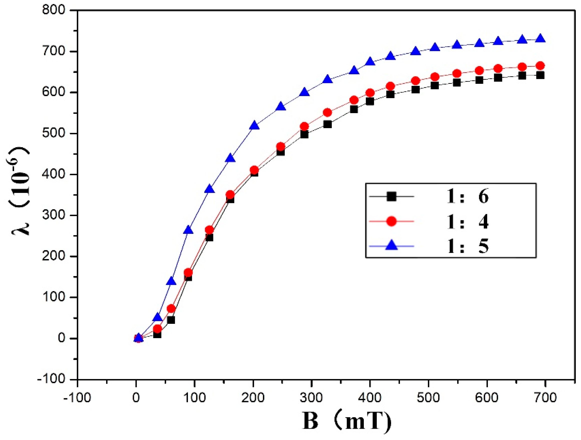
In this paper, the influence of the proportion of TD powder on magnetostrictive composites was studied. When shape and TD particle size were the same, magnetostrictive composites with a mass ratio of epoxy resin to TD powder of 1:4, 1:5, and 1:6 were tested. As shown in Figure 8, when the proportion of TD powder was low (the mass ratio of epoxy resin to TD powder was 1:4), the distance between TD particles was large, and the resin hindered the transmission of magnetostriction, resulting in poor magnetostriction of the composite materials. However, when the proportion of TD powder was too high (the mass ratio of epoxy resin to TD powder was 1:6), the particles in the resin had poor wetting behavior and weak binding force, and they were difficult to mix uniformly; thus, a large number of pores were generated, resulting in a reduction in the magnetostriction of the composite materials. When the mass ratio of epoxy resin to TD powder was 1:5, the proportion of TD powder was moderate, and the magnetostrictive composite exhibited the best magnetostrictive properties.
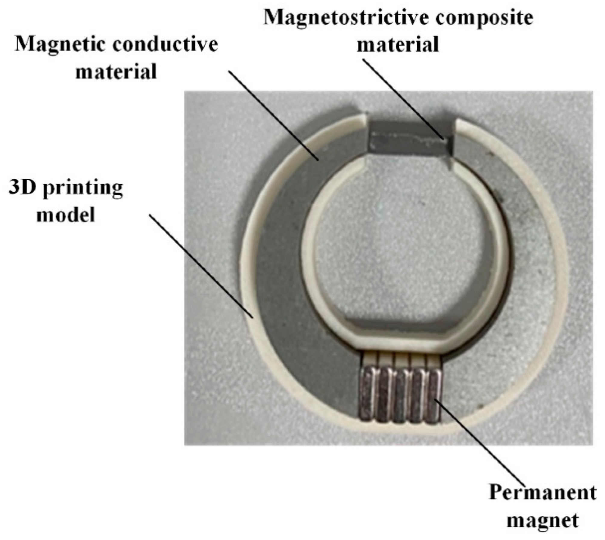
Figure 9 shows the current sensor based on the semi-cylindrical magnetostrictive composite. The proposed sensor was composed of a magnetostrictive composite, magnetic conductive material, permanent magnet, and 3D-printed bracket. The size of TD particles in the magnetostrictive composites was 149–500 μm and the mass ratio of epoxy resin to TD powder was 1:5. The magnetic conductive material was a silicon steel sheet with a magnetic permeability of 7000–10,000. The 3D-printed holder was used to support the sensor.
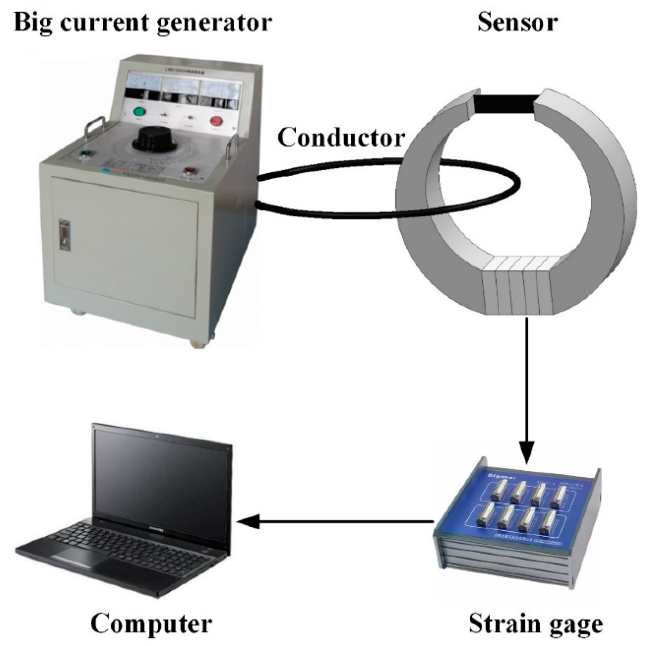
As shown in Figure 10, the test device of the sensor was composed of a current generator, strain gauge, and computer. The current generator could generate 0–1000 A DC or AC.
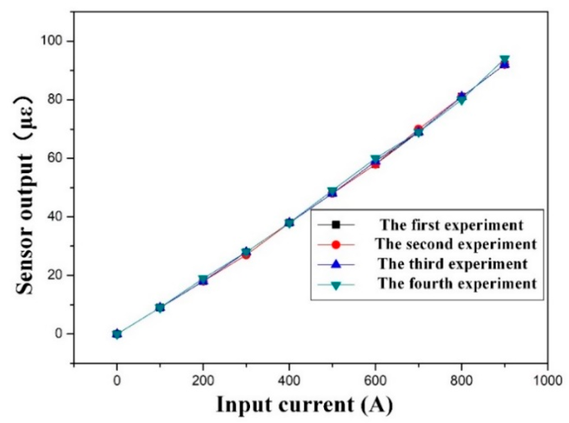
In order to test the repeatability of the sensor, four experiments were done under the same conditions. The sample data for the repeatability test are shown in Table 2. Figure 11 shows the relationship between the strain and the current of the sensor in four experiments. Repeatability (Rep) can be determined using the following equation:
where t is the t-distribution coefficient under confidence equal to 95%, σmax is the maximum output standard deviation, and DFS is the sensor output of the full-scale input, which is 900 A.
The output standard deviation of every input current could be calculated using Equation (2), and the results are shown in Table 3. We can find that the maximum output standard deviation of the sensor was about 1.
where m is the number of samples (m = 4), Dij is the sensor output at the i-th sample and the j-th input current, and is the average output at the j-th input current.
In addition, according to Table 1, DFS was equal to 85, and the coefficient t was about 2.132. Thus, according to Equation (1), the calculated repeatability of the sensor was about 2.51%.
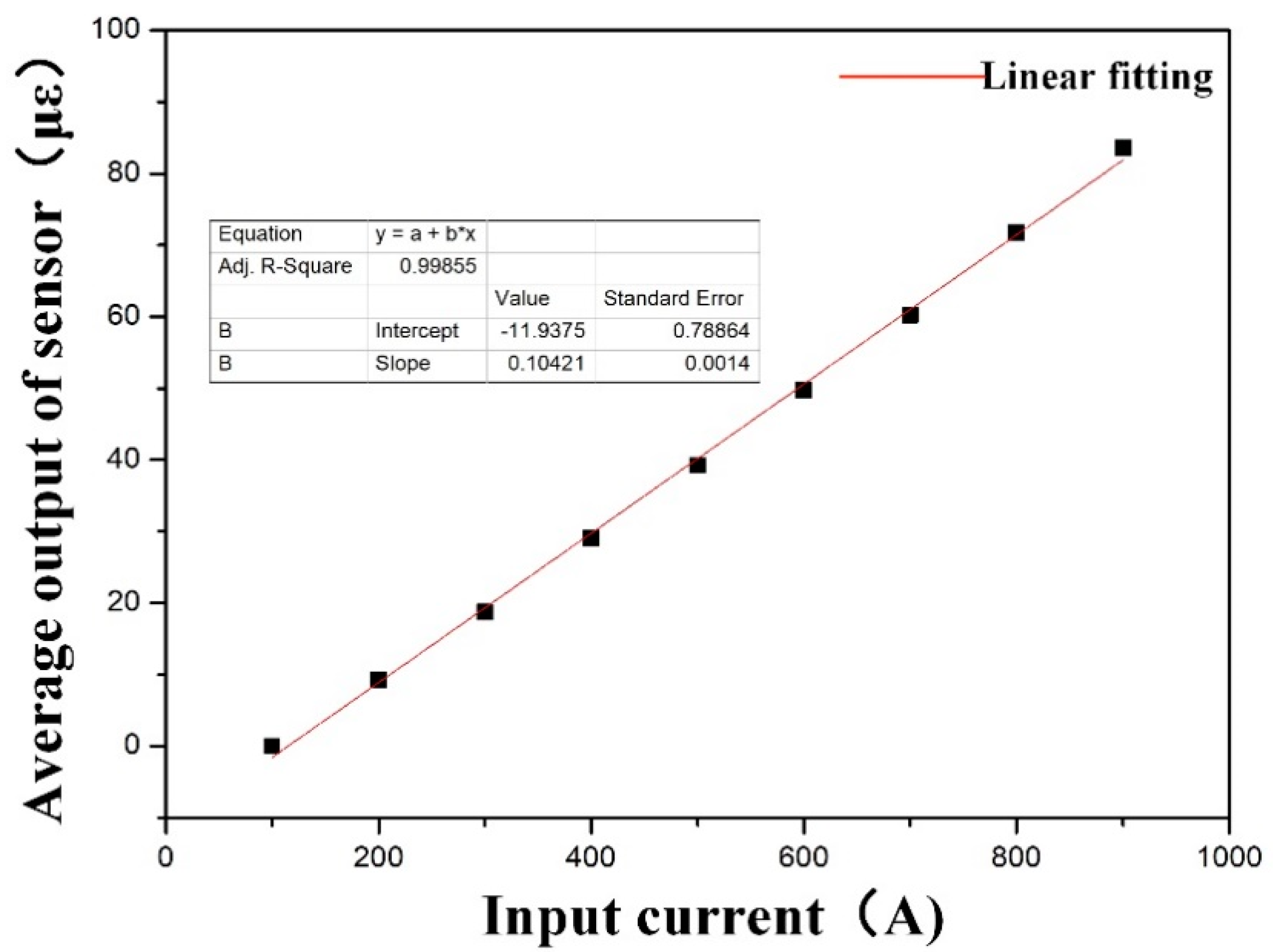
In this paper, the sensitivity of the sensor was tested. The average output of each input current is shown in Table 4. Figure 12 shows the relationship between the average output of the sensor and the input current. It was found that the average output and input current of the sensor followed a good linear fit. The linear working range of the sensor was 100 A–900 A, and the sensitivity was equal to the slope of the fitted curve, which was about 0.104 με/A.
Finally, we summarized the sensors on the basis of magnetostrictive materials in existing references. As shown in Table 5, the TD mass of the sensors proposed by Lopez et al. [17] was the lowest in the existing references, which was 0.42 g. Compared with the previous sensors, the mass of our proposed sensor was reduced by 1/4, the sensitivity was approximately doubled, and the linear working range reached 100–900 A.
4. Conclusions
In this paper, we proposed a low-cost current sensor based on semi-cylindrical magnetostrictive composite. The sensor structure was improved and the performance of magnetostrictive composite was enhanced. FEM simulations were carried out to guide the design of the sensor, and a semi-cylindrical magnetostrictive material was proposed. Terfenol-D alloy is hard, brittle, expensive, and difficult to machine. Magnetostrictive composites of TD powder and epoxy resin were used to replace magnetostrictive materials. The influence of TD particle size and the proportion of TD powder on magnetostrictive composites was studied. The experimental results showed that the size of TD particles was 149–500 µm and the mass ratio of epoxy resin to TD powder was 1:5. The sensitivity, repeatability, and linear working range of the sensor reached 0.104 με/A, 2.51%, and 100–900 A respectively, when only 0.31 g of TD powder was employed. This means that current measurement with low cost, high sensitivity, and wide range was realized.
Author Contributions
Conceptualization, S.X. and M.L.; methodology, Q.P.; validation, F.X. and H.X.; investigation, J.S.; data curation, S.X.; writing—original draft preparation, Q.P.; writing—review and editing, S.X.; visualization, L.M.; supervision, M.L.; project administration, S.X.; funding acquisition, F.X. All authors have read and agreed to the published version of the manuscript.
Funding
This research was funded by the Fundamental Research Funds for the Central Universities (2017QNA13).
Conflicts of Interest
The authors declare no conflict of interest.
References
- Wang, T.Y.; Luo, C.M.; Tian, Y.X. Research on photoelectric current transformer in power system. Autom. Electr. Power Syst. 2000, 1, 38–41. [Google Scholar]
- Li, Y.S.; Liu, J.; Yang, Y.H.; Yu, W.B.; Ji, H.Q.; Xie, X.M. Research on integrated operation of adaptive optical current transformer and protection. J. Chin. Electr. Eng. 2007, 27, 57–62. [Google Scholar]
- Yamagata, Y.; Oshi, T.; Katsukawa, H.; Kato, S.; Sakurai, Y. Development of optical current transformers and application to fault location systems for substation. IEEE Trans. Power Deliv. 1993, 8, 866–873. [Google Scholar] [CrossRef]
- Wang, Z.S.; Wang, H.B.; Liu, X.H. Dynamic response of the output force of giant magnetostrictive materials. Int. J. Mech. Mater. Des. 2020. [Google Scholar] [CrossRef]
- Bennett, S.; Staruch, M.; Matis, B.; Jeffrey, B.; Shu, C.; Konrad, B.; Peter, F. The Realization of an Artificial Magnetoelectric Heterostructure (FeCo/AlN) Micro-Beam Resonator for Ultra-High Sensitivity Magnetic Sensing Applications; APS March Meeting; American Physical Society: College Park, MD, USA, 2017. [Google Scholar]
- Su, J.; Niekiel, F.; Fichtner, S.; Thormaehlen, L.; Kirchhof, C.; Meyners, D.; Quandt, E.; Wagner, B.; Lofink, F. AlScN-based MEMS magnetoelectric sensor. Appl. Phys. Lett. 2020, 117, 132903. [Google Scholar] [CrossRef]
- Mora, J.; Diez, A.; Cruz, J.L.; Andres, M.V. A magnetostrictive sensor interrogated by fiber gratings for DC-current and temperature discrimination. IEEE Photonics Technol. Lett. 2000, 12, 1680–1682. [Google Scholar] [CrossRef]
- Chiang, K.S.; Kancheti, R.; Rastogi, V. Temperature-compensated fiber-Bragg-grating-based magnetostrictive sensor for dc and accurrents. Opt. Eng. 2003, 42, 1906–1909. [Google Scholar] [CrossRef]
- Satpathi, D.; Moore, J.A.; Ennis, M.G. Design of a Terfenol-D based fiber-optic current transducer. IEEE Sens. J. 2005, 5, 1057–1065. [Google Scholar] [CrossRef]
- Cremonezi, A.O.; Ferreira, E.C.; Biazon, A.J.; Dias, J.A.S. A fiber bragg grating RMS current transducer based on the magnetostriction effect using a Terfenol-D toroidal-shaped modulator. IEEE Sens. J. 2013, 13, 683–690. [Google Scholar] [CrossRef]
- De Nazaré, F.V.B.; Werneck, M.M. Compact Optomagnetic Bragg-Grating-Based Current Sensor for Transmission Lines. IEEE Sens. J. 2015, 15, 100–109. [Google Scholar] [CrossRef]
- Dante, A.; Lopez, J.D.; Carvalho, C.C.; da Silva Barros Allil, R.C.; Werneck, M.M.; Werneck, M.M. A compact FBG-Based toroidal magnetostrictive current sensor with reduced mass of Terfenol-D. IEEE Photonics Technol. Lett. 2019, 31, 1461–1464. [Google Scholar] [CrossRef]
- Wang, S.; Wan, F.; Zhao, H.; Chen, W.; Zhang, W.; Zhou, Q. A sensitivity-enhanced fiber grating current sensor based on giant mag-netostrictive material for large-current measurement. Sensors 2019, 19, 1755. [Google Scholar] [CrossRef] [PubMed] [Green Version]
- Adelsberg, N.; Weber, Y.; Yoffe, A.; Shilo, D. Wireless thin layer force sensor based on a magnetostrictive composite material. Smart Mater. Struct. 2017, 26, 065013. [Google Scholar] [CrossRef]
- Quintero, S.; Braga, A.; Weber, H.; Bruno, A.C.; Araujo, J.F.D.F. A magnetostrictive composite-fiber bragg grating sensor. Sensors 2010, 10, 8119–8128. [Google Scholar] [CrossRef] [PubMed] [Green Version]
- Lopez, J.D.; Dante, A.; Bacurau, R.M.; Cremonezi, A.O.; Mok, R.W.; Carvalho, C.C.; Allil, R.C.S.B.; Ferreira, E.C.; Werneck, M.M. Fiber-Optic current sensor based on FBG and optimized magnetostrictive composite. IEEE Photonics Technol. Lett. 2019, 31, 1987–1990. [Google Scholar] [CrossRef]
- Lopez, J.D.; Dante, A.; Cremonezi, A.O.; Bacurau, R.M.; Carvalho, C.C.; da Silva Barros Allil, R.C.; Ferreira, E.C.; Werneck, M.M. Fiber-Optic current sensor based on FBG and Terfenol-D with magnetic flux concentration for enhanced sensitivity and linearity. IEEE Photonics Technol. Lett. 2020, 20, 3572–3578. [Google Scholar] [CrossRef]
Figure 1.
Design of sensor.

Figure 2.
The magnetic flux density distribution of sensors with different structures at a current of 400 A. (a) sensor based on the cuboid magnetostrictive material. (b) sensor based on the cylindrical magnetostrictive material. (c) sensor based on the semi-cylindrical magnetostrictive material.
Figure 2.
The magnetic flux density distribution of sensors with different structures at a current of 400 A. (a) sensor based on the cuboid magnetostrictive material. (b) sensor based on the cylindrical magnetostrictive material. (c) sensor based on the semi-cylindrical magnetostrictive material.

Figure 3.
The magnetic flux density range at the position of magnetostrictive material. (a) Sensor based on the cuboid magnetostrictive material. (b) Sensor based on the cylindrical magnetostrictive material. (c) Sensor based on the semi-cylindrical magnetostrictive material.
Figure 3.
The magnetic flux density range at the position of magnetostrictive material. (a) Sensor based on the cuboid magnetostrictive material. (b) Sensor based on the cylindrical magnetostrictive material. (c) Sensor based on the semi-cylindrical magnetostrictive material.

Figure 4.
The manufacturing procedure of silicone mold. (A) glue A and glue B were mixed in a container. (B) the whole mixture was intensively stirred. (C) the mixture was poured into a 3D-printed holder. (D) a silicone mold was obtained.
Figure 4.
The manufacturing procedure of silicone mold. (A) glue A and glue B were mixed in a container. (B) the whole mixture was intensively stirred. (C) the mixture was poured into a 3D-printed holder. (D) a silicone mold was obtained.

Figure 5.
The manufacturing procedure of magnetostrictive composites. (A) a measured volume of hardener was added to epoxy resin. (B) a Terfenol-D powder was introduced. (C) the whole mixture was intensively stirred. (D) the mixture was poured into silicone mold. (E) the silicone mold with the mixture was subjected to polarization. (F) the semi-cylindrical magnetostrictive composite was obtained.

Figure 6.
Testing device of magnetostrictive composite material.

Figure 7.
The influence of Terfenol-D (TD) particle size on magnetostrictive composites.

Figure 8.
The influence of the proportion of TD powder on magnetostrictive composites.

Figure 9.
The current sensor based on the semi-cylindrical magnetostrictive composite.

Figure 10.
Testing device of sensor.

Figure 11.
Repeatability test of sensor.

Figure 12.
Sensitivity test of sensor.


Table 1.
Summary of sensors with different structures.
| Magnetostrictive Material Shape | Magnetostrictive Material Volume (mm3) | Magnetic Flux Density (mT) |
|---|---|---|
| Cuboid [17] | 240.0 | 21.8–32.0 |
| Cylindrical | 188.4 | 23.6–33.5 |
| Semi-cylindrical | 94.2 | 25.1–34.9 |
Table 2.
Sample data for the repeatability test.
| Output (με) | Input Current (A) | ||||||||
|---|---|---|---|---|---|---|---|---|---|
| 100 | 200 | 300 | 400 | 500 | 600 | 700 | 800 | 900 | |
| 1 | 0 | 10 | 19 | 29 | 40 | 51 | 60 | 71 | 85 |
| 2 | 0 | 9 | 18 | 28 | 39 | 49 | 61 | 72 | 83 |
| 3 | 0 | 9 | 19 | 29 | 39 | 50 | 60 | 72 | 83 |
| 4 | 0 | 9 | 19 | 29 | 39 | 49 | 60 | 72 | 83 |
Table 3.
Standard deviation results.
| Input Current (A) | |||||||||
|---|---|---|---|---|---|---|---|---|---|
| 100 | 200 | 300 | 400 | 500 | 600 | 700 | 800 | 900 | |
| SD | 0 | 0.50 | 0.50 | 0.50 | 0.50 | 0.96 | 0.50 | 0.50 | 1 |
Table 4.
Average output of every input current.
| Output (με) | Input Current (A) | ||||||||
|---|---|---|---|---|---|---|---|---|---|
| 100 | 200 | 300 | 400 | 500 | 600 | 700 | 800 | 900 | |
| Average | 0 | 9.25 | 18.75 | 28.75 | 39.25 | 49.75 | 60.25 | 71.75 | 83.50 |
Publisher’s Note: MDPI stays neutral with regard to jurisdictional claims in published maps and institutional affiliations. |
© 2020 by the authors. Licensee MDPI, Basel, Switzerland. This article is an open access article distributed under the terms and conditions of the Creative Commons Attribution (CC BY) license (http://creativecommons.org/licenses/by/4.0/).
Share and Cite
MDPI and ACS Style
Xu, S.; Peng, Q.; Xing, F.; Xue, H.; Sun, J.; Ma, L.; Li, M. A Low-Cost Current Sensor Based on Semi-Cylindrical Magnetostrictive Composite. Electronics 2020, 9, 1833. https://doi.org/10.3390/electronics9111833
AMA Style
Xu S, Peng Q, Xing F, Xue H, Sun J, Ma L, Li M. A Low-Cost Current Sensor Based on Semi-Cylindrical Magnetostrictive Composite. Electronics. 2020; 9(11):1833. https://doi.org/10.3390/electronics9111833
Chicago/Turabian StyleXu, Shaoyi, Qiang Peng, Fangfang Xing, Hongyu Xue, Junwen Sun, Lei Ma, and Ming Li. 2020. "A Low-Cost Current Sensor Based on Semi-Cylindrical Magnetostrictive Composite" Electronics 9, no. 11: 1833. https://doi.org/10.3390/electronics9111833
Note that from the first issue of 2016, this journal uses article numbers instead of page numbers. See further details here.