
Background Material Identification Using a Soft Robot
by
 ,
,
Nathan Jeong
1,* ,
,
Wooseop Lee
1,
Seongcheol Jeong
2,
Arun Niddish Mahendran
3 and
Vishesh Vikas
3 1
Department of Electrical and Computer Engineering, The University of Alabama, Tuscaloosa, AL 35487, USA
2
Eco-Friendly Vehicle R&D Division, Korea Automotive Technology Institute, Cheonan 31003, Republic of Korea
3
Department of Mechanical Engineering, The University of Alabama, Tuscaloosa, AL 35487, USA
*
Author to whom correspondence should be addressed.
Electronics 2024, 13(1), 78; https://doi.org/10.3390/electronics13010078
Submission received: 29 November 2023
/
Revised: 17 December 2023
/
Accepted: 20 December 2023
/
Published: 23 December 2023
Abstract
:Soft robotics is an emerging technology that provides robots with the ability to adapt to the environment and safely interact with it. Here, the ability of these robots to identify the surface of interaction is critical for grasping and locomotion tasks. This paper describes the capability of a four-limb soft robot that can identify background materials through the collection of reflection coefficients using an embedded antenna and machine learning techniques. The material of a soft-limb robot was characterized in terms of the relative permittivity and the loss tangent for the design of an antenna to collect reflection coefficients. A slot antenna was designed and embedded into a soft limb in order to extract five features in reflection coefficients including the resonant frequency, −3 dB bandwidth taken from the lowest S11, the value of the lowest S11, −3 dB bandwidth taken from the highest S11, and the number of resonant frequencies. A soft robot with the embedded antenna was tested on nine different background materials in an attempt to identify surrounding terrain information and a better robotic operation. The tested background materials included concrete, fabric, grass, gravel, metal, mulch, soil, water, and wood. The results showed that the robot was capable of distinguishing among the nine different materials with an average accuracy of 93.3% for the nine background materials using a bagged decision-tree-based ensemble method algorithm.
1. Introduction
Soft robots have garnered immense interest in recent years due to the highly deformable and continuum nature of the soft material [1,2]. They belong to a subset of robotics that focuses on technologies that more closely resemble the physical characteristics of living organisms. Soft robots are the perfect candidates for commercial rescue operations where situations can become too dangerous for direct human involvement [3,4]. They can also find use in military applications where dangerous scenarios and rough, varied terrain are common. These extensive abilities are made possible by the characteristics of soft materials, which are mechanically durable and resistant to extreme heat, chemicals, and other dangers such as radiation [5,6,7]. They also exhibit increased durability and adaptability when compared to other materials. Succinctly, soft materials are defined relative to the environment of interaction—‘a bulk or composite collection of matter that undergoes deformations of similar or greater magnitude than the deformation of the environment, either plastically or elastically, within the force regime applied by its environment’ [8]. A robot with soft materials has the potential to vary its Gaussian curvature and surface profile when designed and actuated appropriately [9]. Additionally, its ability to interact with the environment can affect locomotion [10]. The surface of locomotion, referred to as background in this paper, has critical influence on the robot locomotion ability [11].
Conceptually, locomotion results from difference in forces acting on the robot body [11]. Consequently, terrain identification is critical for developing adaptive locomotion control and planning strategies over different surfaces [4,12]. Simply put, these adaptations are executed by humans when walking on asphalt (rigid, high-friction), sand (soft, granular), and ice (rigid, low-friction). Specifically for soft robots, locomotion gaits are seldom discovered for a robot or surface—instead, they are obtained by observing animals (bio-inspired) or through intuition (ad hoc). This is primarily due to their continuum nature and lack of good models to describe robot–environment interaction. Hence, the identification of terrain for locomotion will benefit soft roboticists by exploring more surface-specific gaits through data-driven approaches. Solving this problem will propel soft robots to be deployed for search and rescue operations as well as exploration applications where robots are required to maneuver complex terrains. Soft proprioception has been explored by embedding resistive sensors inside the robot body and using a recurrent neural network [13]. Similarly, optical tactile sensors have been used to detect the deformation of a surface [14]. In one instance, sEMG was integrated to a soft robotic exomusculature glove for hand rehabilitation [15]. However, these sensors are either bulky, rigid, or complicated for a robot system.
A flexible, simple, and low-profile sensor can be beneficial to provide the appropriate locomotion of a soft robot. A thin and planar antenna may be a good candidate to be incorporated into a soft robot. For instance, an antenna can be embedded in a limb of a soft robot and may sense surface material to improve the locomotion of a soft robot. Additionally, the collected environmental data from an antenna can be used to identify the surroundings of a soft robot using machine learning techniques. Combining the beneficial attributes of the soft material with machine learning techniques could enable intelligent, efficient background material identification. This would allow humans to remotely identify surrounding terrain information and to conduct better robotic operations.
In this paper, a novel soft robot with a flexible antenna embedded in its limb is proposed in order for the soft robot to recognize background material using a machine learning algorithm and in order to improve locomotion. Reflection coefficients of the antenna were measured and used in machine learning algorithms to identify various background materials. The remaining sections of the paper will proceed as follows. Section 2 discusses the 4-limb soft robot, followed by a description of the antenna design at the soft robot’s limb in Section 3. Section 4 explains the measurement of reflection coefficients and background material identification. A thorough discussion of the results is then presented in Section 5, leading to the conclusion of the proposed design.
2. Four-Limb Soft Robot
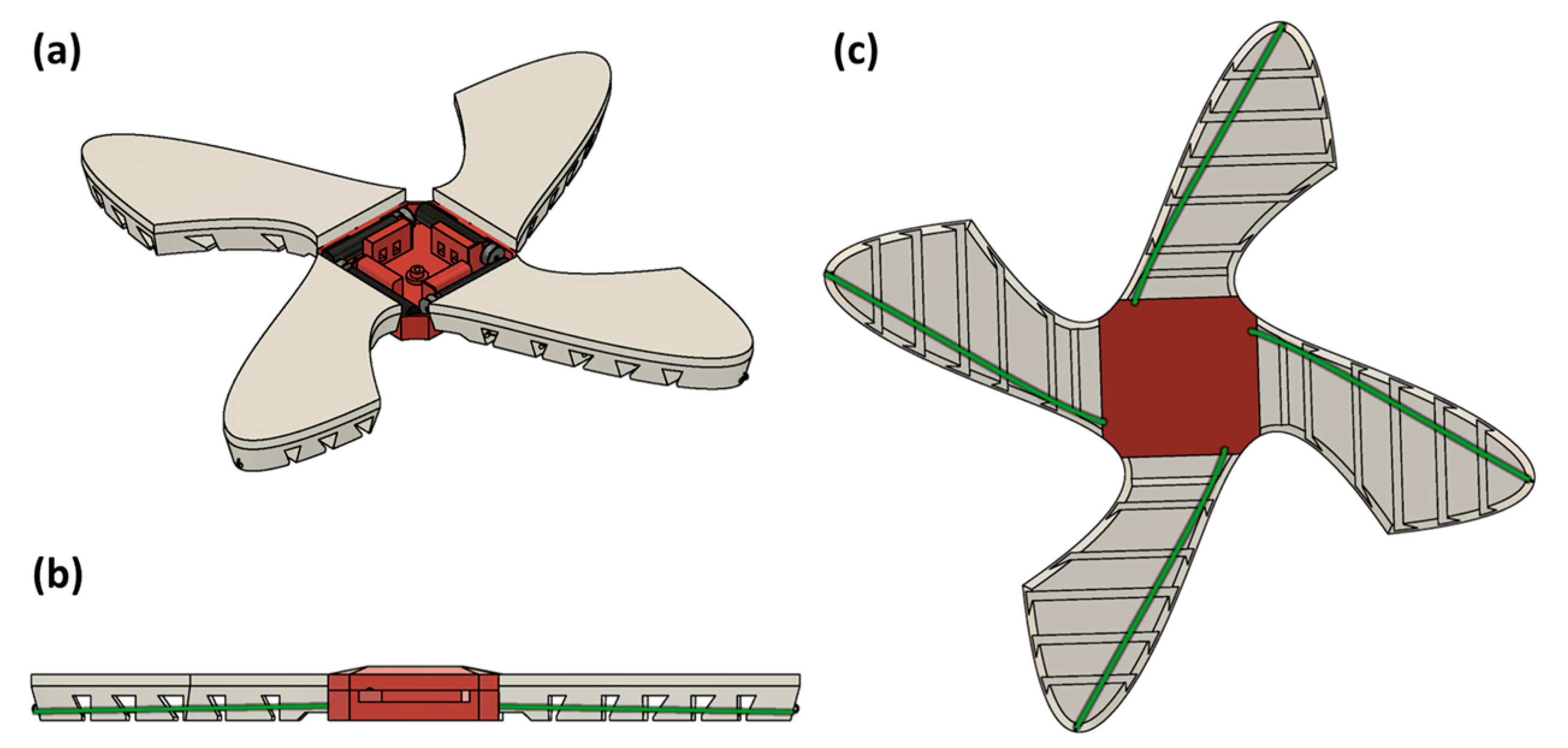
The robot used in this experiment was a four-limb motor-tendon-actuated soft robot. The design was the result of topology optimization in order to allow six identical robots to reconfigure into a sphere [9]. As such, the limbs were designed for complex geometrical curling and not optimized for any particular locomotion modes. However, all possible motions were quasistatic, and all robot configurations were statically stable. The fabrication of such a robot involved the integration of soft material limbs, control, and actuation payload (motors, electronics), as well as the routing of the tendons through the limb as shown in Figure 1.
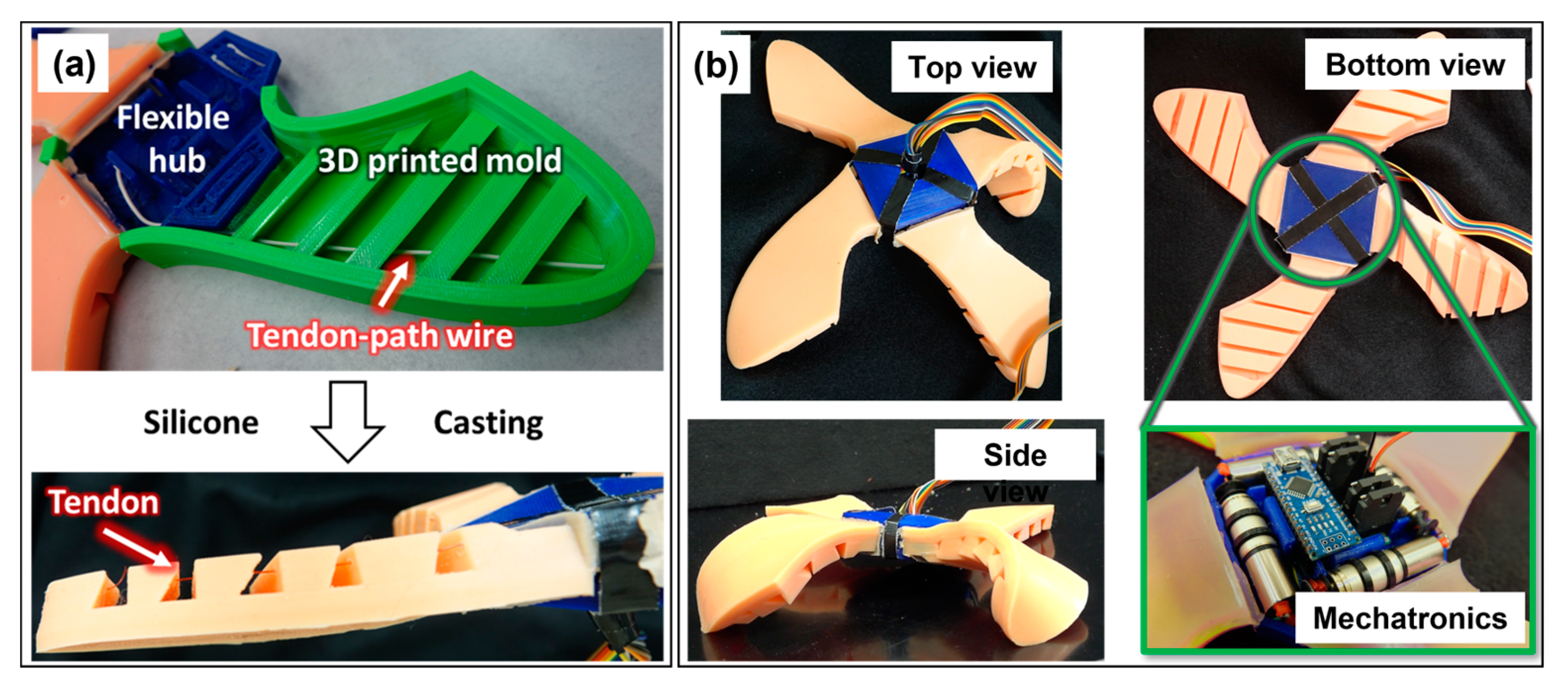
The modular fabrication process involved mixing two liquid silicone components (Smooth-On Dragon Skin Part A and B [16]) degassed in vacuo. The molding material for the soft robot was 3D printed with polylactic acid (PLA). The tendon paths were cast by threading a thick wire through the rigid 3D printed mold as shown in Figure 2, which was removed upon curing of the cast. The central hub was 3D printed out of flexible filament and placed in the mold for casting; the casting was repeated for the other limbs. A rapid curling and uncurling of the flexible limbs (<0.5 s/transition) was achieved through motor-tendon actuation. Four DC motors with 3D-printed PLA spools were placed in the hub and secured using zip ties. Teflon tubing was inserted into the individual fins of each limb to prevent tears caused by the difference in stiffness between the silicone and the fishing line tendon, as shown in Figure 2. Finally, a fishing line attached to the spool was routed through each fin and anchored at the end with a fishing hook. The design parameters of the fins of each limb (separation, height, thickness, etc.) were experimentally determined to maximize curling while still permitting uncurling upon relaxing the motor.
The design of such a robot involved the integration of soft material (silicone rubber body) with rigid actuators (motors, electronics, and a fishing line). The disparity of stiffness between soft–hard materials resulted in stress concentration. These challenges were solved by introducing stiffness gradient solutions. Primarily, the flexible hub allowed for rigid motors and electronics to be integrated inside a soft body with minimum movement and disturbance. The flexible hub also housed the common antenna feed. The limbs of the robot were designed to ensure the seamless integration of the antenna inside the body. Here, the stiffness mismatch was minimal and did not require any intermediary material. As such, the embedded antennas were able to flex with the soft limbs and conform to background materials, intelligently identifying them. When considering the stability of the robot, unlike legged robots, the center of mass for this robot was near the ground where the entire body touched the surface in its resting position. Additionally, given the distributed mass and the robot design, the robot demonstrated stability during motion on flat and inclined surfaces.
3. Antenna Design
3.1. Characterization of Soft Skin
Prior to designing an antenna for identifying background materials, it was necessary to characterize the dielectric properties of the soft limbs made of Dragon Skin. The dielectric properties for their characterization included the relative permittivity () and loss tangent (). Two striplines and a microstrip ring resonator were fabricated and measured to find the relative permittivity and loss tangent, respectively. The verification of the results was conducted through electromagnetic simulation.
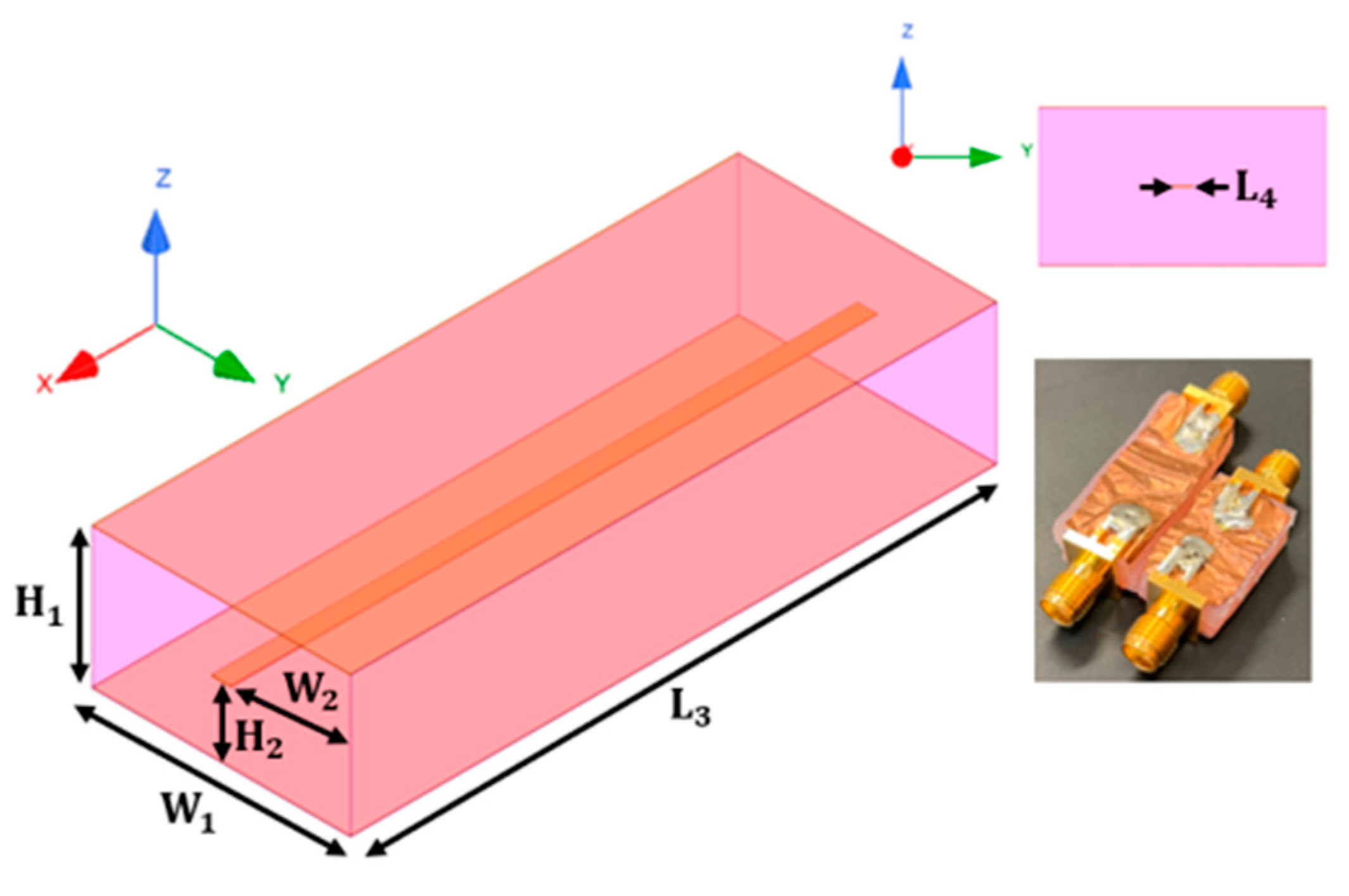
First, to determine the relative permittivity, two striplines with different lengths were fabricated with Dragon Skin material. This physical length difference was used to find the phase angle difference between the two striplines. A stripline is composed of a single conductive strip line in the middle of the soft material and two ground planes on the top and bottom, as shown in Figure 3. This three-conductor configuration can support a quasi-TEM (Transverse Electromagnetic) mode, which allows for plane wave propagation along the line inside the unknown dielectric.
Table 1 indicates the parameters and values for the two different lengths of the striplines. Note that was set to be 20 mm for the short stripline and 30 mm for the long stripline, while the other parameters remained the same. SMA connectors were connected at both sides of the lines, as depicted in Figure 3. A full two-port measurement was conducted with the vector network analyzer (Keysight, Santa Rosa, CA, USA, E8364). The transmission coefficient () was obtained from 800 MHz to 8 GHz. The phase angle difference was calculated by subtracting the phase angle of from that of . Then, the relative permittivity was calculated based on the phase angle difference of the transmitted waves, as shown in Equation (1) below.
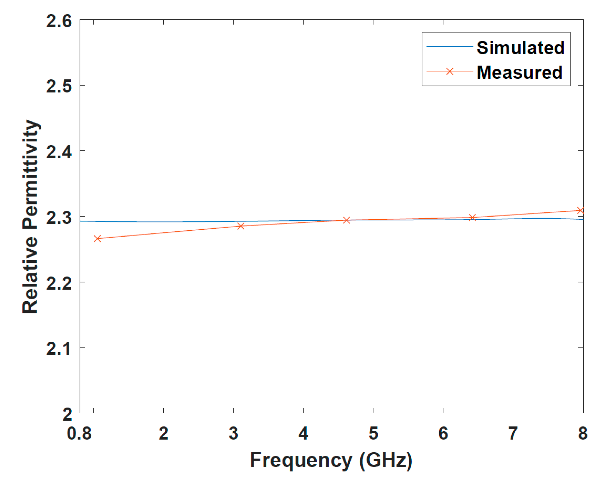
where f is the operation frequency, is the speed of light, is the difference in phase angles between the two striplines, and is the physical length difference of the striplines. Both the calculated and measured results were in good agreement and showed that the relative permittivity of the Dragon Skin material varied from 2.27 to 2.31 from 800 MHz to 8 GHz, as shown in Figure 4.
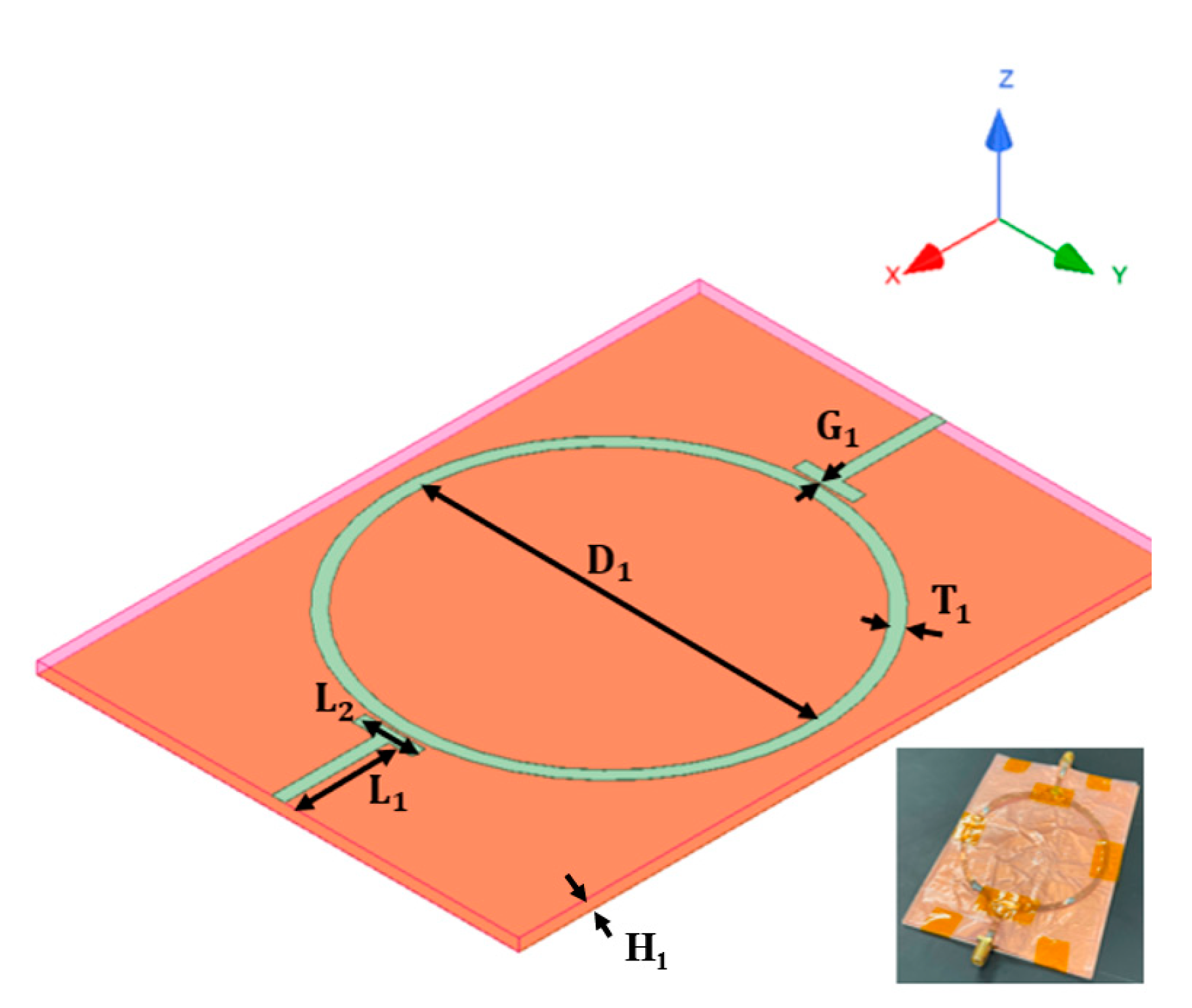
Now, in order to find the loss tangent, a microstrip ring resonator was fabricated on 2 mm thick Dragon Skin material. This configuration is shown in Figure 5. The dimensions of the design parameters are summarized in Table 1. The gap () between the T-shape microstrip input and output lines and the ring structure was established to introduce capacitive coupling between them. The diameter () of the ring was chosen to resonate at 915 MHz and at its harmonic resonant frequencies. The −3 dB bandwidth was obtained by subtracting the upper frequency and the lower frequency at the half-power points. The tangent loss of the soft material was then computed using the quality factor (Q) in the following equation [17].
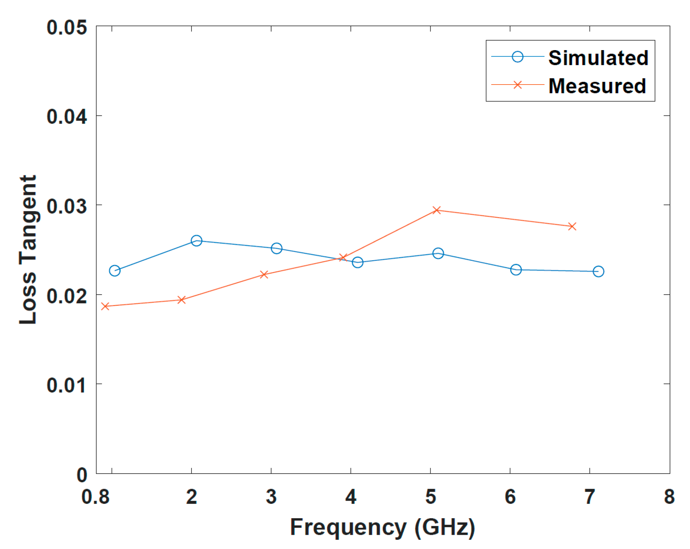
where is the center frequency of the ring resonator, and is the −3 dB frequency bandwidth. The measured results indicated that the loss tangent varied from 0.019 to 0.031 from 800 MHz to 6.8 GHz.
To validate the measurement results, electromagnetic simulation was conducted with Ansys HFSS (High-Frequency Structure Simulator) [18]. This addition process also allowed us to design an antenna inside the dielectric in a simulation. Wave ports were used to excite electromagnetic waves at the input and output of the lines. The simulated results showed that the relative permittivity and loss tangent were well aligned with the measurement result, as shown in Figure 5 and Figure 6. These resultant values for the relative permittivity and loss tangent were used to design the antenna, which would be embedded in the soft limbs in order to identify background materials.
3.2. Slot Antenna
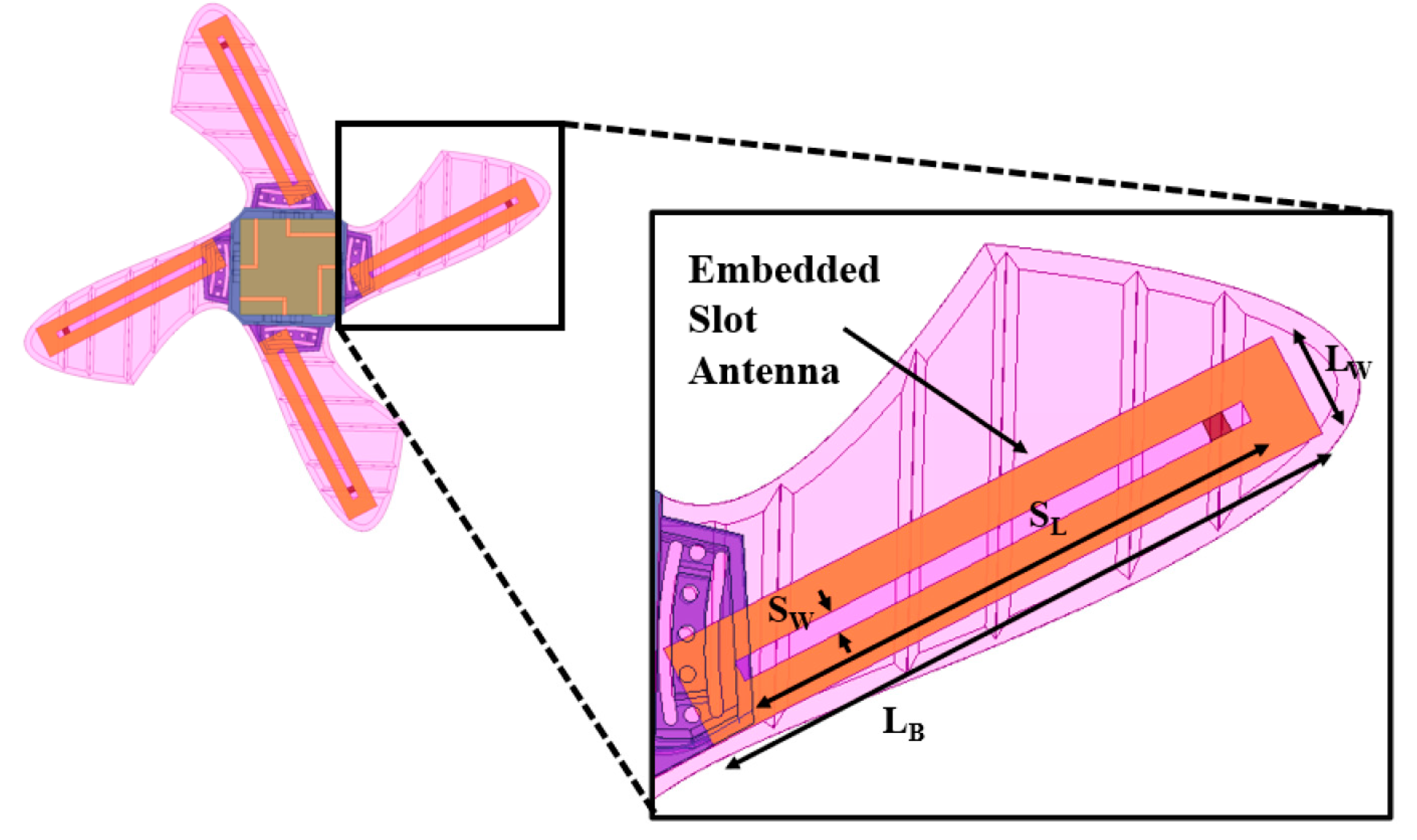
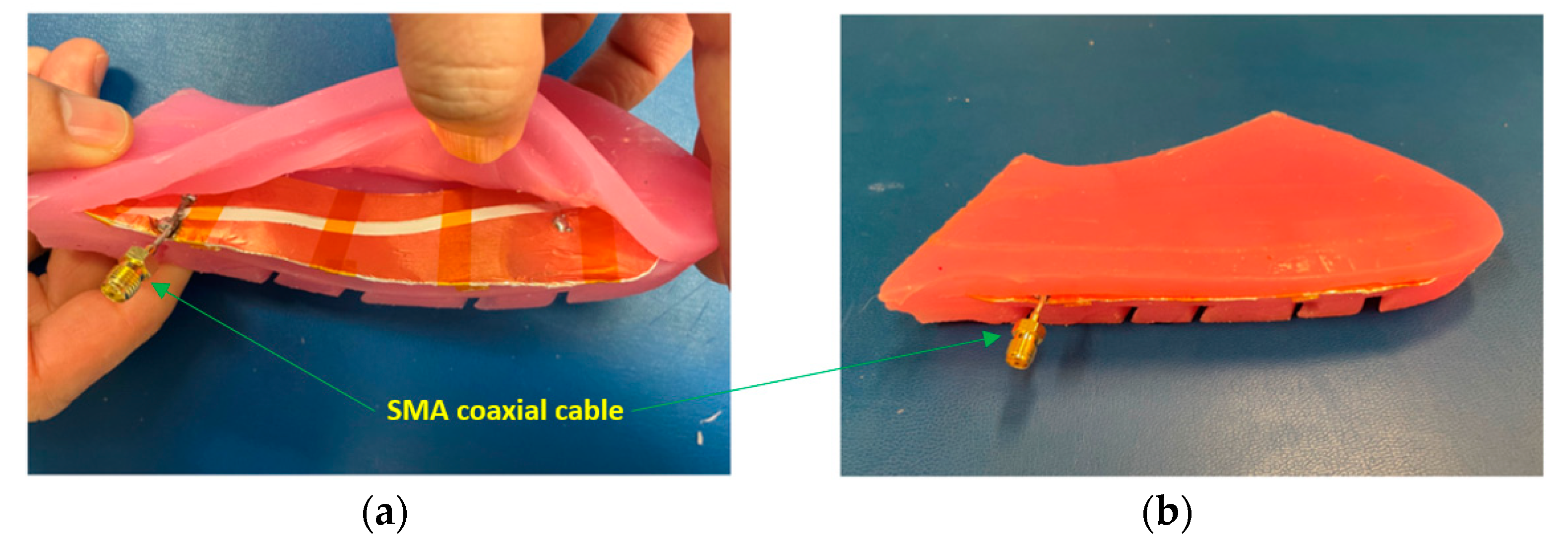
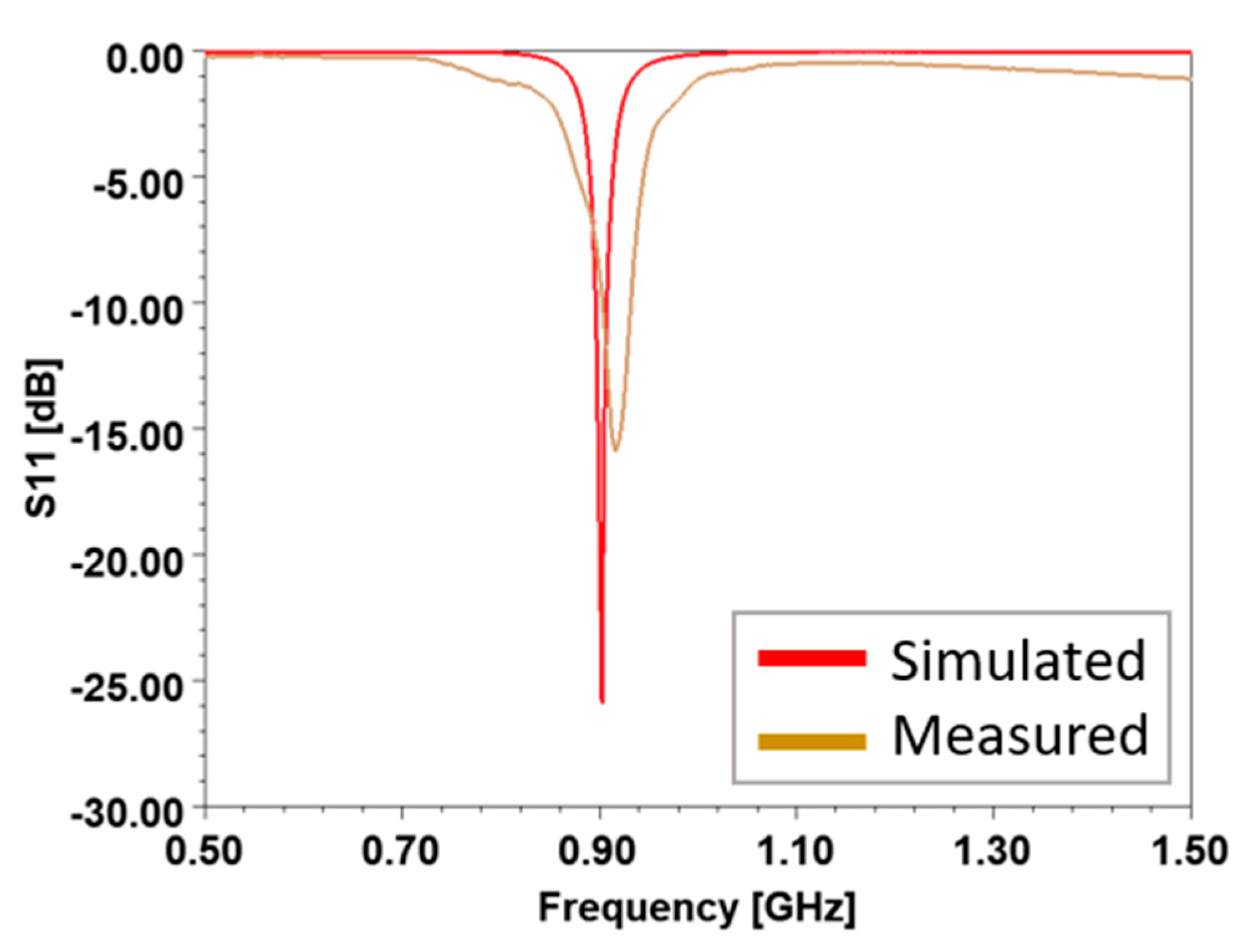
The locomotion of soft robots requires conformity to various surfaces for movement and effective material identification. Thus, an antenna inside the robot limbs needed to be able to be flexible, compact, and efficient in electromagnetic radiation. Considering these requirements, a slot antenna was chosen and embedded into the soft limbs, as depicted in Figure 7. The slot length () was calculated to be 112 mm to generate a resonance at 915 MHz, and the slot width () was determined to be 4 mm for better impedance matching to cover from 902 to 918 MHz of the ISM (Industrial, Scientific, and Medical) band. A 32 μm thick copper film was used to configure the slot antenna. The antenna feeding point was off centered in the slot to match to 50 and located 4 mm from the end of the slot. To embed the slot antenna into each limb, a thin slit was cut in the upper part of the limb. Then, the thin copper film was inserted. A semi-rigid coaxial cable was used to excite the slot, as illustrated in Figure 8. Then, the coaxial cable was connected to the NanoVNA [19] to measure the reflection coefficient (i.e., S11) of the slot antenna embedded in the robot limb. Both the simulated and measured reflection coefficients are shown in Figure 9. The proposed slot antenna in the soft limb resonated at 915 MHz with 16 MHz bandwidth. The slight difference in the resonance frequency was due to fabrication imperfection.
4. Background Material Identification
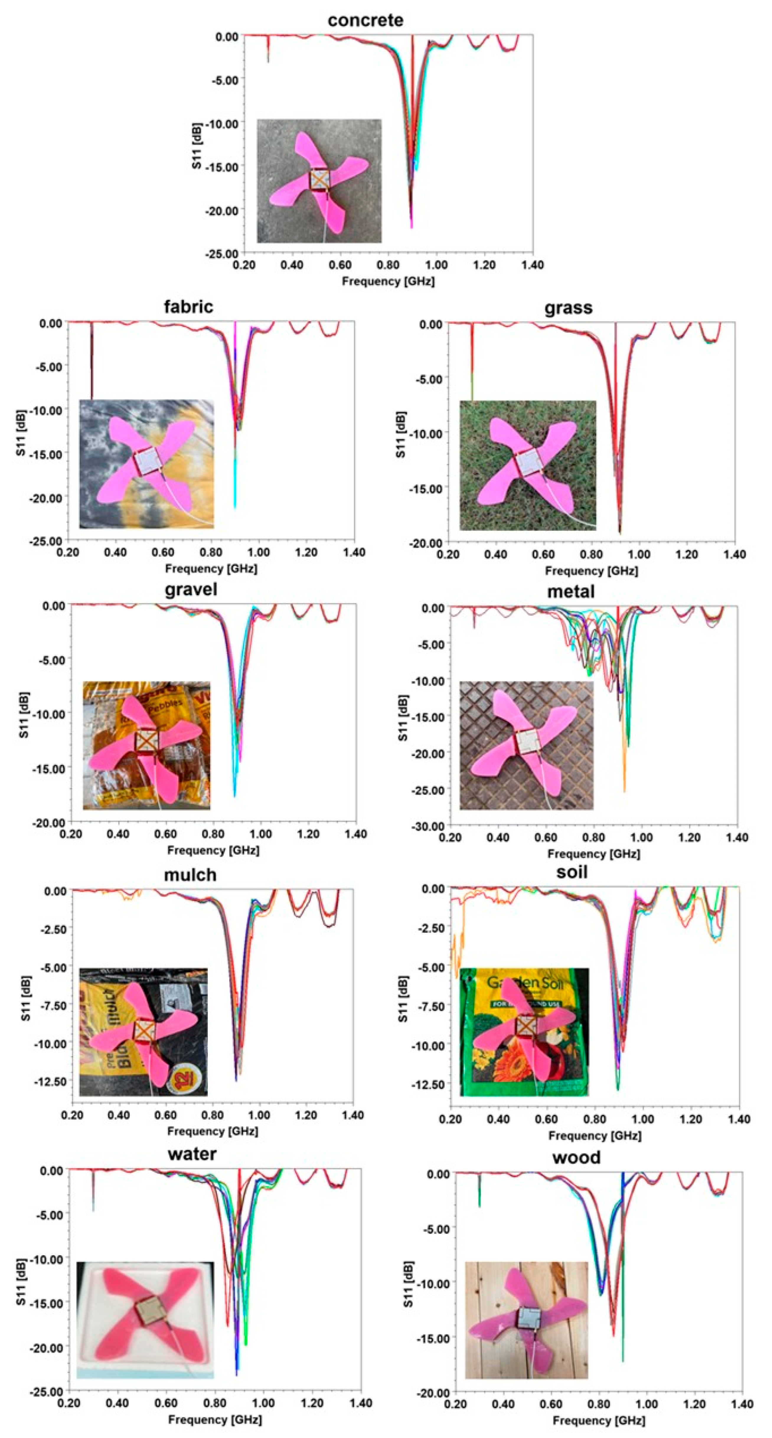
With the slot antenna operating, resonating at the 915 MHz ISM band and embedded in the soft robot, reflection coefficients were measured on nine different background materials. A two-port portable NanoVNA [19] was used to measure the reflection coefficient (i.e., S11) of the soft robot antenna from 0.2 to 1.4 GHz. Fifteen measurements were conducted for each material, as shown in different colors at Figure 10, resulting in a total of 150 datasets. For each of the nine background materials, the same kind of (but slightly different) configuration of the materials was measured to represent various material compositions. For example, for grass, we measured S11 in thin, thick, weedy, mossy, and dense grass with different heights, varying from 1 cm to 5 cm. Table 2 lists all the background materials used in this study, as well as their descriptions and thickness.
After importing all 150 reflection coefficient files, the fifteen measurements for each background material were plotted together, as shown in Figure 10. The results show that the S11 curves varied for different materials as a function of the frequency. According to the theory of antenna engineering, the features for machine learning algorithms were chosen based on the characteristics of the reflection coefficient curves of the slot antenna. We extracted five features—(1) resonant frequency, (2) −3 dB bandwidth referring from the lowest S11, (3) the lowest value of S11, (4) −3 dB bandwidth referring from the highest S11, and (5) the number of resonances. Therefore, these five features were extracted from the S11 plots and inputted to machine learning algorithms to classify the background materials. The mean and standard deviation (SD) of the five features for the nine background materials are summarized in Table 3. Concrete, metal, water, and wood demonstrated high standard deviation in general. MATLAB’s Classification Algorithms, including decision trees, discriminant analysis, Bayesian methods, support-vector machine (SVM) algorithms, k-nearest neighbor (kNN) algorithms, and ensemble methods, were used for classification. The purpose of training the various machine learning (ML) models was to find the best ML algorithm for this study. Hyper parameters for each model were tuned to achieve higher accuracy.
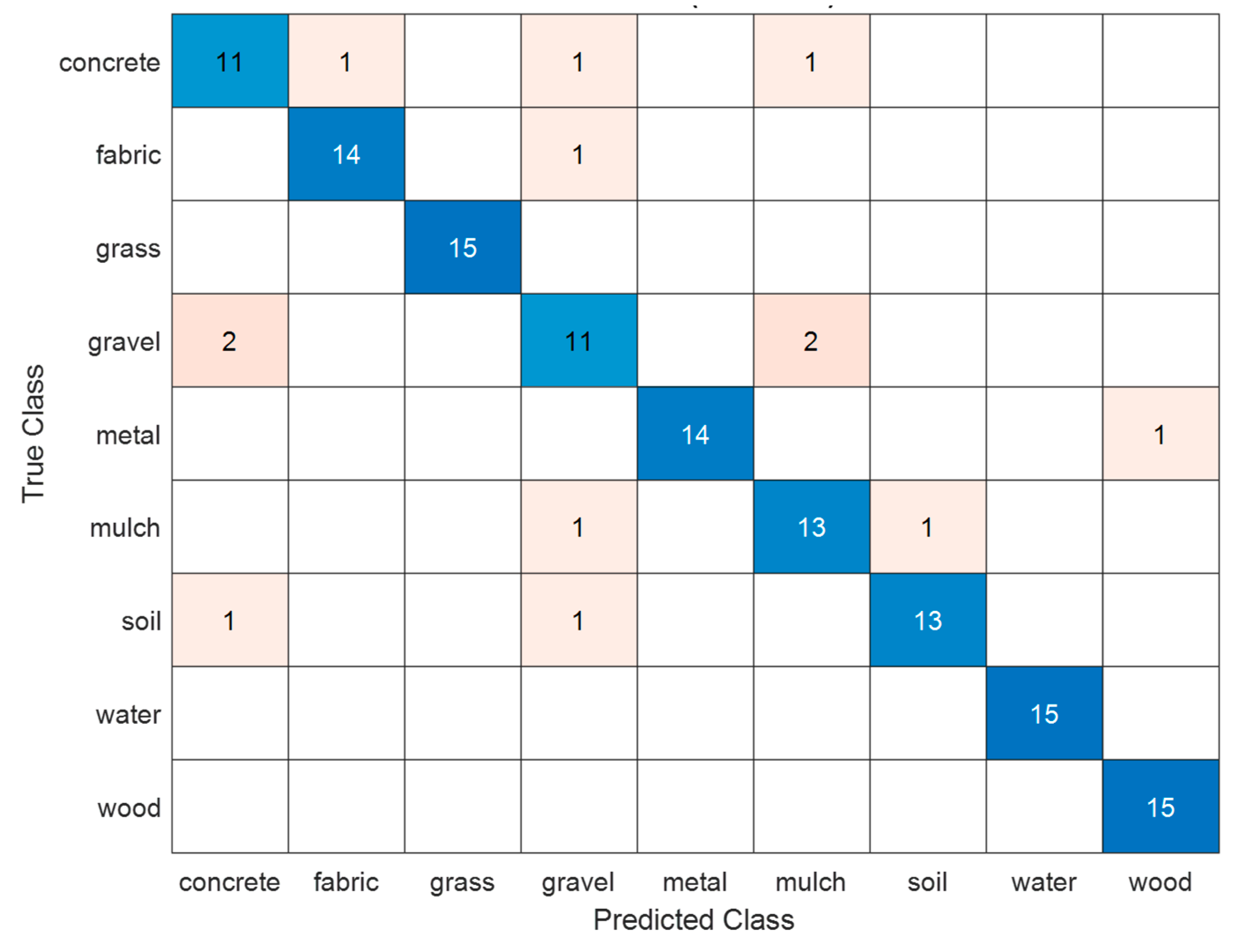
Among the machine learning models trained, the bag-based ensemble method with q decision tree as a learner provided the highest accuracy of 93.3%. The maximum number of splits was 133, and the number of learners was 30. The deep and wide neural network-based algorithm was not appropriate, due to the fact that the soft robot had limited space and power to run a higher performance computing unit. Table 4 shows the accuracies for decision trees, linear discriminant, naïve Bayes, SVM, k-nearest neighbor, ensemble method, and neural network. Both ensemble method and SVM resulted in more than 90% accuracy. The number of cross-validation folds were also set to 5. These cross-validation folds protected against overfitting by partitioning the dataset into folds and estimating the accuracy of each fold. To find which feature was more critical than the others, we conducted an ablation study by excluding a feature out of five features at a time, and we found that the most influential features were −3 dB bandwidth taken from the highest S11 and resonant frequency, followed by the number of resonant frequencies, value of the lowest S11, and −3 dB bandwidth taken from the lowest S11. The detailed results of the ablation study are shown in Table 5. All the machine learning algorithms used indicated that −3 dB bandwidth taken from the lowest S11 was the most critical feature. The next important features were the center frequency and the number of resonances in order. The features of −3 dB bandwidth taken from the lowest S11 and the lowest S11 value did not provide significant contributions to the accuracy. Given the small standard deviation in the most influencing features, the number of experimental samples (15 per material) was deemed to be sufficient to investigate the use of machine learning methods. Figure 11 shows the confusion matrix. Generally, the predictions were fairly accurate, indicating that the proposed soft robot antenna was effective at identifying various background materials based on the extracted features. A comparison to other background material identification techniques is provided in Table 6. The proposed design identified more materials with better accuracy than other comparable works incorporating the antenna into a capable soft robot. Note that reference [29] used a commercial WiFi device, such as a router, to identify a material.
5. Discussion
The enhancement of the perception ability of soft robots includes the identification of the surface of contact to alter robot control strategies for applications relating to terrestrial locomotion and gripping where the robot–environment interaction is critical. In this context, this research explores a new approach regarding embedding a radiating antenna inside a soft robot body to identify background materials. Here, a slot antenna was designed at a 915 MHz ISM band and embedded inside a limb that was fabricated using silicone elastomer. The fabrication methodology discussed was agnostic to the soft polymer used for the antenna design—e.g., dipole, patch, or an array antenna—as well as the ISM frequency band, e.g., 13.35 MHz, 400 MHz, or 2.4 GHz. This was due to the data-driven approach that is utilized for training and classification. The reflection coefficients were measured, and the feature vector comprised the resonant frequency, −3 dB bandwidth taken from the lowest S11, the value of the lowest S11, −3 dB bandwidth taken from the highest S11, and the number of resonances. An ensemble method-based classification approach was utilized over 9 materials, with 15 experiments per material and with a 93.3% accuracy. The experimental results indicated effectiveness and ability to identify a wide range of materials with different thicknesses, including concrete, grass, gravel, mulch, soil, wood, fabric, and water. When compared with other systems where the sensor is embedded inside the robot, the proposed approach was seen to be the most promising. This research work can be useful for many areas, such as soft rehabilitation devices [38,39,40], soft underwater robots [41,42], and soft surgical tools [43]. The limitation of this work is that the measurement was made using the external coaxial cable and NanoVNA. Their actual implementation in an active robot will require a measurement method to obtain the reflection coefficient. This work explored the ability of antenna-based soft robots for the identification of single surfaces using an ensemble method classifier. Given the promise of this approach, more complex deep learning methods will be considered in the future, and tests will be conducted on more complex surfaces. Moreover, composite surfaces comprising layers of multiple materials will be examined for their reflection coefficients. This will be beneficial to identify below-surface materials as well using a minimally invasive approach in applications like search and rescue. Additionally, a dual band or triple band antenna may be used to extract more distinctive features from the reflection coefficients. This may increase detection accuracy and the number of background materials to be identified.
6. Conclusions
A novel approach for soft robot identification of background materials is presented in this work. This approach measures the reflection coefficient using an embedded slot antenna and utilizes an ensemble-based ML algorithm to classify the nine common materials, with an accuracy of 93.3%. The base material of the soft limbs was characterized to find the relative permittivity and loss tangent, which were required in order to design the slot antenna. The simulation results were in good agreement with the measurement results of the resonance frequency of the antenna. The frequency band used to identify the background material was an ISM band centered around 915 MHz. This soft-material and antenna-design agnostic data-driven approach provides an extremely promising solution to surface identification for soft robots interacting with their environment.
Author Contributions
Conceptualization, N.J., W.L., S.J., A.N.M. and V.V.; methodology, N.J., W.L., S.J., A.N.M. and V.V.; software, N.J. and W.L.; validation, N.J., W.L., S.J., A.N.M. and V.V.; formal analysis, N.J., W.L. and S.J.; investigation, N.J., W.L., S.J., A.N.M. and V.V.; resources, N.J. and V.V.; data curation, W.L.; writing—original draft preparation, N.J., W.L., S.J., A.N.M. and V.V.; writing—review and editing, N.J. and V.V.; visualization, N.J., W.L., S.J., A.N.M. and V.V.; supervision, N.J. and V.V. All authors have read and agreed to the published version of the manuscript.
Funding
This research received no external funding.
Data Availability Statement
Data are contained within the article.
Conflicts of Interest
The authors declare no conflict of interest.
References
- Kim, S.; Laschi, C.; Trimmer, B. Soft robotics: A bioinspired evolution in robotics. Trends Biotechnol. 2013, 31, 287–294. [Google Scholar] [CrossRef] [PubMed]
- Laschi, C.; Mazzolai, B.; Cianchetti, M. Soft robotics: Technologies and systems pushing the boundaries of robot abilities. Sci. Robot. 2016, 1, eaah3690. [Google Scholar] [CrossRef] [PubMed]
- Lee, C.; Kim, M.; Kim, Y.J.; Hong, N.; Ryu, S.; Kim, H.J.; Kim, S. Soft robot review. Int. J. Control Autom. Syst. 2017, 15, 3–15. [Google Scholar] [CrossRef]
- Calisti, M.; Picardi, G.; Laschi, C. Fundamentals of soft robot locomotion. J. R. Soc. Interface 2017, 14, 20170101. [Google Scholar] [CrossRef] [PubMed]
- Elango, N.; Faudzi, A.A.M. A review article: Investigations on soft materials for soft robot manipulations. Int. J. Adv. Manuf. Technol. 2015, 80, 1027–1037. [Google Scholar] [CrossRef]
- Marechal, L.; Balland, P.; Lindenroth, L.; Petrou, F.; Kontovounisios, C.; Bello, F. Toward a Common Framework and Database of Materials for Soft Robotics. Soft Robot. 2020, 8, 284–297. [Google Scholar] [CrossRef]
- Whitesides, G.M. Soft Robotics. Angew. Chem. Int. Ed. 2018, 57, 4258–4273. [Google Scholar] [CrossRef] [PubMed]
- Kastor, N.; Vikas, V.; Cohen, E.; White, R.D. A definition of soft materials for use in the design of robots. Soft Robot 2017, 4, 181–182. [Google Scholar] [CrossRef] [PubMed]
- Freeman, C.; Maynard, M.; Vikas, V. Topology and morphology design of spherically reconfigurable homogeneous modular soft robots. Soft Robot. 2023, 10, 52–65. [Google Scholar] [CrossRef] [PubMed]
- Vikas, V.; Grover, P.; Trimmer, B. Model-free control framework for multi-limb soft robots. In Proceedings of the 2015 IEEE/RSJ International Conference on Intelligent Robots and Systems (IROS), Hamburg, Germany, 28 September–2 October 2015; pp. 1111–1116. [Google Scholar]
- Radhakrishnan, V. Locomotion: Dealing with friction. Proc. Natl. Acad. Sci. USA 1998, 95, 5448–5455. [Google Scholar] [CrossRef] [PubMed]
- Ordonez, C.; Shill, J.; Johnson, A.; Clark, J.; Collins, E. Terrain identification for RHex-type robots. In Proceedings of the Unmanned Systems Technology XV, Baltimore, MD, USA, 1–3 May 2013; pp. 240–251. [Google Scholar]
- Thuruthel, T.G.; Shih, B.; Laschi, C.; Tolley, M.T. Soft robot perception using embedded soft sensors and recurrent neural networks. Sci. Robot. 2019, 4, eaav1488. [Google Scholar] [CrossRef] [PubMed]
- Ward-Cherrier, B.; Pestell, N.; Cramphorn, L.; Winstone, B.; Giannaccini, M.E.; Rossiter, J.; Lepora, N.F. The tactip family: Soft optical tactile sensors with 3d-printed biomimetic morphologies. Soft Robot. 2018, 5, 216–227. [Google Scholar] [CrossRef] [PubMed]
- Delph, M.A.; Fischer, S.A.; Gauthier, P.W.; Luna, C.H.M.; Clancy, E.A.; Fischer, G.S. A soft robotic exomusculature glove with integrated sEMG sensing for hand rehabilitation. In Proceedings of the 2013 IEEE 13th International Conference on Rehabilitation Robotics (ICORR), Seattle, WA, USA, 24–26 June 2013; pp. 1–7. [Google Scholar]
- Smooth-On. Dragon Skin™ 20. Available online: https://www.smooth-on.com/products/dragon-skin-20/ (accessed on 19 September 2023).
- Pozar, D.M. Microwave Engineering; Wiley: Hoboken, NJ, USA, 2011. [Google Scholar]
- Ansys. Ansys HFSS. Available online: https://www.ansys.com/products/electronics/ansys-hfss (accessed on 18 September 2023).
- Groups.io. NanoVNA. Available online: https://nanovna.com/ (accessed on 19 September 2023).
- Depot, T.H. Vigoro 0.5 cu. ft. Bagged Pea Gravel Pebble Landscape Rock. Available online: https://www.homedepot.com/p/Vigoro-0-5-cu-ft-Bagged-Pea-Gravel-Pebble-Landscape-Rock-54255/202523000 (accessed on 14 September 2023).
- Depot, T.H. Vigoro 0.5 cu. ft. Bagged River Pebble Landscape Rock. Available online: https://www.homedepot.com/p/Vigoro-0-5-cu-ft-Bagged-River-Pebble-Landscape-Rock-54250V/100558618 (accessed on 14 September 2023).
- Depot, T.H. Vigoro 0.5 cu. ft. Bagged Pond Pebble Landscape Rock. Available online: https://www.homedepot.com/p/Vigoro-0-5-cu-ft-Bagged-Pond-Pebble-Landscape-Rock-54249V/100550970 (accessed on 14 September 2023).
- Depot, T.H. Vigoro 2 cu. ft. Bagged Premium Black Wood Mulch. Available online: https://www.homedepot.com/p/Vigoro-2-cu-ft-Bagged-Premium-Black-Wood-Mulch-52050197/205606445 (accessed on 14 September 2023).
- Depot, T.H. Vigoro 2 cu. ft. Bagged Premium Red Wood Mulch. Available online: https://www.homedepot.com/p/Vigoro-2-cu-ft-Bagged-Premium-Red-Wood-Mulch-480978/205606416 (accessed on 14 September 2023).
- Depot, H. Evergreen 2 cu. ft. Cypress Mulch Blend. Available online: https://www.homedepot.com/p/2-cu-ft-Cypress-Mulch-Blend-52050045/203579960 (accessed on 19 September 2023).
- Depot, T.H. Miracle-Gro Garden Soil All Purpose for In-Ground Use, 1 cu. ft. Available online: https://www.homedepot.com/p/Miracle-Gro-Garden-Soil-All-Purpose-for-In-Ground-Use-1-cu-ft-70551430/312540716 (accessed on 14 September 2023).
- Depot, T.H. Vigoro 1 cu. ft. All Purpose Garden Soil for In-Ground Use for Fruits, Flowers, Vegetables and Herbs. Available online: https://www.homedepot.com/p/Vigoro-1-cu-ft-All-Purpose-Garden-Soil-for-In-Ground-Use-for-Fruits-Flowers-Vegetables-and-Herbs-72171920/300457596 (accessed on 14 September 2023).
- Depot, T.H. Kellogg Garden Organics 2 cu. ft. All Natural Garden Soil for Flowers and Vegetables. Available online: https://www.homedepot.com/p/Kellogg-Garden-Organics-2-cu-ft-All-Natural-Garden-Soil-for-Flowers-and-Vegetables-6850/205617876 (accessed on 14 September 2023).
- Feng, C.; Xiong, J.; Chang, L.; Wang, J.; Chen, X.; Fang, D.; Tang, Z. WiMi: Target material identification with commodity Wi-Fi devices. In Proceedings of the 2019 IEEE 39th International Conference on Distributed Computing Systems (ICDCS), Dallas, TX, USA, 7–10 July 2019; pp. 700–710. [Google Scholar]
- Njogu, P.; Jablonski, P.; Shastri, A.; Sanz-Izquierdo, B. Origami Boat Sensing Antenna. In Proceedings of the 2021 15th European Conference on Antennas and Propagation (EuCAP), Dusseldorf, Germany, 22–26 March 2021; pp. 1–5. [Google Scholar]
- Windau, J.; Shen, W.-M. An inertia-based surface identification system. In Proceedings of the 2010 IEEE International Conference on Robotics and Automation, Anchorage, AK, USA, 3–7 May 2010; pp. 2330–2335. [Google Scholar]
- Kerr, E.; McGinnity, T.M.; Coleman, S. Material classification based on thermal properties—A robot and human evaluation. In Proceedings of the 2013 IEEE International Conference on Robotics and Biomimetics (ROBIO), Shenzhen, China, 12–14 December 2013; pp. 1048–1053. [Google Scholar]
- Aldhaeebi, M.; Jamil, K.; Sebak, A.R. Ultra-wideband antenna for RFID underground oil industry application. In Proceedings of the 2014 2nd International Conference on Artificial Intelligence, Modelling and Simulation, Madrid, Spain, 18–20 November 2014; pp. 333–338. [Google Scholar]
- Xiao, W.; Yang, J.; Fang, H.; Zhuang, J.; Ku, Y.; Zhang, X. Development of an automatic sorting robot for construction and demolition waste. Clean Technol. Environ. Policy 2020, 22, 1829–1841. [Google Scholar] [CrossRef]
- Wang, J.; Xiong, J.; Chen, X.; Jiang, H.; Balan, R.K.; Fang, D. TagScan: Simultaneous target imaging and material identification with commodity RFID devices. In Proceedings of the 23rd Annual International Conference on Mobile Computing and Networking, Snowbird, UT, USA, 16–20 October 2017; pp. 288–300. [Google Scholar]
- Kim, J.; Lee, J. Real-time estimation of maximum friction and optimal slip ratio based on material identification for a mobile robot on rough terrain. In Proceedings of the 2013 13th International Conference on Control, Automation and Systems (ICCAS 2013), Gwangju, Republic of Korea, 20–23 October 2013; pp. 1708–1713. [Google Scholar]
- Ukkonen, L.; Sydanheirno, L.; Kivikoski, M. A novel tag design using inverted-F antenna for radio frequency identification of metallic objects. In Proceedings of the 2004 IEEE/Sarnoff Symposium on Advances in Wired and Wireless Communications, Princeton, NJ, USA, 26–27 April 2004; pp. 91–94. [Google Scholar]
- Polygerinos, P.; Wang, Z.; Galloway, K.C.; Wood, R.J.; Walsh, C.J. Soft robotic glove for combined assistance and at-home rehabilitation. Robot. Auton. Syst. 2015, 73, 135–143. [Google Scholar] [CrossRef]
- Proietti, T.; O’Neill, C.; Gerez, L.; Cole, T.; Mendelowitz, S.; Nuckols, K.; Hohimer, C.; Lin, D.; Paganoni, S.; Walsh, C. Restoring arm function with a soft robotic wearable for individuals with amyotrophic lateral sclerosis. Sci. Transl. Med. 2023, 15, eadd1504. [Google Scholar] [CrossRef] [PubMed]
- Yoder, Z.; Kellaris, N.; Chase-Markopoulou, C.; Ricken, D.; Mitchell, S.K.; Emmett, M.B.; Segil, J.; Keplinger, C. Design of a high-speed prosthetic finger driven by Peano-HASEL actuators. Front. Robot. AI 2020, 181, 586216. [Google Scholar] [CrossRef] [PubMed]
- Wang, T.; Joo, H.-J.; Song, S.; Hu, W.; Keplinger, C.; Sitti, M. A versatile jellyfish-like robotic platform for effective underwater propulsion and manipulation. Sci. Adv. 2023, 9, eadg0292. [Google Scholar] [CrossRef] [PubMed]
- Li, G.; Chen, X.; Zhou, F.; Liang, Y.; Xiao, Y.; Cao, X.; Zhang, Z.; Zhang, M.; Wu, B.; Yin, S. Self-powered soft robot in the Mariana Trench. Nature 2021, 591, 66–71. [Google Scholar] [CrossRef] [PubMed]
- McCandless, M.; Wise, F.J.; Russo, S. A Soft Robot with Three Dimensional Shape Sensing and Contact Recognition Multi-Modal Sensing via Tunable Soft Optical Sensors. In Proceedings of the 2023 IEEE International Conference on Robotics and Automation (ICRA), London, UK, 29 May–2 June 2023; pp. 573–580. [Google Scholar]
Figure 1.
Configuration of the soft robot. (a) a four-limb soft robot with motor-tendon actuators where the flexible central ‘hub’ holds the mechatronics. (b,c) The tendon paths are indicated in green.
Figure 1.
Configuration of the soft robot. (a) a four-limb soft robot with motor-tendon actuators where the flexible central ‘hub’ holds the mechatronics. (b,c) The tendon paths are indicated in green.

Figure 2.
(a) The soft robot is cast using a rigid mold and a tendon-path wire. (b) The motors with spools and mechatronics are placed inside the hub.
Figure 2.
(a) The soft robot is cast using a rigid mold and a tendon-path wire. (b) The motors with spools and mechatronics are placed inside the hub.

Figure 3.
Stripline to extract the relative permittivity.

Figure 4.
Simulated and measured relative permittivity.

Figure 5.
Ring resonator to extract loss tangent.

Figure 6.
Simulated and measured loss tangents.

Figure 7.
Soft robot with the slot antenna embedded in its limbs. = 4 mm, = 104 mm, = 125 mm, and = 20 mm.
Figure 7.
Soft robot with the slot antenna embedded in its limbs. = 4 mm, = 104 mm, = 125 mm, and = 20 mm.

Figure 8.
Slot antenna integrated to the soft robot. (a) Fabricated limb with the slot antenna embedded and (b) the final limb with the SMA rigid cable.
Figure 8.
Slot antenna integrated to the soft robot. (a) Fabricated limb with the slot antenna embedded and (b) the final limb with the SMA rigid cable.

Figure 9.
Simulated and measured reflection coefficients.

Figure 10.
Measured reflection coefficients from nine different background materials. The different colored lines indicate the fifteen measurements of the reflection coefficients.
Figure 10.
Measured reflection coefficients from nine different background materials. The different colored lines indicate the fifteen measurements of the reflection coefficients.

Figure 11.
Confusion matrix result for nine different background materials.


Table 1.
Dimensions of the striplines and the ring resonator (unit in mm).
| Striplines | Ring Resonator | ||
|---|---|---|---|
| 13 | 17.27 | ||
| 4.25 | 10 | ||
| 6.7 | 70.3 | ||
| 3.35 | 2.18 | ||
| 20 for long and 30 for short lines | 0.4 | ||
| 3.5 | 2 | ||
Table 2.
Name, description, and thickness of background materials tested.
| Material | Description | Thickness (cm) |
|---|---|---|
| Concrete | Various Exterior Locations | 6, 13, 28, 30, 45 |
| Fabric | Cotton, Polyester, Blend (Cotton, Polyester, and Nylon) | 4, 8 |
| Grass | Thin, Weedy, Mossy, Thick, Dense | 1, 2, 3, 4, 5 |
| Gravel | Vigoro Pea [20], River [21], Pond Pebbles [22] | 8, 10 |
| Metal | Rogers AD1000, RO3006, Microwave Oven, Shelf, Manhole Cover | 0.05, 0.06, 0.3, 2.54, 3.4 |
| Mulch | Vigoro Black [23], Red Mulch [24], Evergreen Cypress Mulch Blend [25] | 12 |
| Soil | Miracle-Gro [26], Vigoro [27], Kellogg Garden Soils [28] | 8, 12 |
| Water | Various Depths atop Styrofoam Base | 0.5, 0.7, 0.9, 1.1, 1.3 |
| Wood | Shelf, Desk, Thick Condensed Wood | 1.8, 3.8, 3.9, 10.1, 11.5 |
Table 3.
Mean and standard deviation of five features from reflection coefficients for nine different background materials.
Table 3.
Mean and standard deviation of five features from reflection coefficients for nine different background materials.
| Material | Center Frequency (MHz) | −3 dB Bandwidth, Lowest (MHz) | Depth of S11 (dB) | −3 dB Bandwidth, Highest (MHz) | Number of Resonances | |||||
|---|---|---|---|---|---|---|---|---|---|---|
| Mean | SD | Mean | SD | Mean | SD | Mean | SD | Mean | SD | |
| Concrete | 902.1 | 16.3 | 16.9 | 5.2 | −17.2 | 2.23 | 96.9 | 2.12 | 1 | 0 |
| Fabric | 910.1 | 7.1 | 27.2 | 3.2 | −11.4 | 1.25 | 91.4 | 1.02 | 1 | 0 |
| Grass | 900.1 | 9.7 | 21.1 | 4.0 | −15.7 | 2.12 | 112.4 | 3.05 | 1 | 0 |
| Gravel | 904.7 | 8.7 | 21.6 | 5.4 | −12.9 | 1.92 | 96.9 | 1.95 | 1 | 0 |
| Metal | 769.0 | 33.5 | 41.1 | 13.6 | −8.2 | 2.83 | 163.2 | 19.2 | 2.7 | 0.57 |
| Mulch | 912.6 | 6.5 | 38.4 | 9.4 | −10.9 | 1.05 | 96.8 | 1.94 | 1 | 0 |
| Soil | 897.9 | 8.1 | 35.7 | 8.3 | −10.3 | 1.39 | 97.0 | 1.93 | 1 | 0 |
| Water | 867.3 | 16.6 | 28.6 | 12.7 | −15.9 | 4.01 | 96.7 | 1.91 | 1.7 | 0.44 |
| Wood | 837.8 | 26.9 | 33.6 | 11.3 | −12.1 | 1.61 | 140.9 | 9.3 | 1 | 0 |
Table 4.
Background identification accuracy of various machine learning algorithms.
| Machine Learning Model | Accuracy (%) |
|---|---|
| Decision Trees | 89.6 |
| Linear Discriminant | 78.4 |
| Naive Bayes | 87.3 |
| Support-Vector Machine | 90.3 |
| K-Nearest Neighbor | 79.1 |
| Ensemble Method | 92.5 |
| Neural Network | 83.6 |
Table 5.
Accuracy results of the ablation study. The listed feature was excluded during machine learning, while the other remaining features were the same.
Table 5.
Accuracy results of the ablation study. The listed feature was excluded during machine learning, while the other remaining features were the same.
| Machine Learning Model | Center Freq. | −3 dB, Lowest | −3 dB, Highest | S11 Depth | No. of Res. |
|---|---|---|---|---|---|
| Decision Trees | 79.1 | 91.0 | 62.7 | 88.8 | 87.3 |
| Linear Discriminant | 75.4 | 76.1 | 64.9 | 79.9 | 76.9 |
| Naive Bayes | 63.4 | 88.8 | 62.7 | 88.1 | 88.1 |
| Support-Vector Machine | 75.4 | 90.3 | 71.6 | 87.3 | 87.3 |
| K-Nearest Neighbor | 72.4 | 76.1 | 62.7 | 83.6 | 79.1 |
| Ensemble Method | 76.1 | 90.3 | 70.1 | 91.0 | 89.6 |
| Neural Network | 71.6 | 85.1 | 66.4 | 85.8 | 82.1 |
Table 6.
Comparison of background material identification techniques.
| Technology | Robot Based | Frequency | Number of Materials | Accuracy (%) |
|---|---|---|---|---|
| WiFi-based material identification [29] | No | 5.15–5.85 GHz | 10 | 95.0 |
| Origami boat sensing antenna [30] | Yes | 1–6 GHz | 3 | N/A |
| Inertia-based surface identification system [31] | Yes | N/A | 5 | 85.0 |
| Robot tactile sensor [32] | Yes | N/A | 11 | 73.0 |
| UWB antenna for oil industry [33] | No | 650, 866, 1372, 2500 MHz | 4 | 90.0 |
| Automatic sorting robot [34] | Yes | N/A | 4 | 94.3 |
| Tagscan material identification [35] | No | 920–924 MHz | 16 | 93.0 |
| Mobile robot with wheel-terrain Interaction [36] | Yes | N/A | 3 | 80.1 |
| Inverted-F antenna for RF Identification [37] | No | 916 MHz | 3 | 98.5 |
| This work | Yes | 902–928 MHz | 9 | 93.3 |
Disclaimer/Publisher’s Note: The statements, opinions and data contained in all publications are solely those of the individual author(s) and contributor(s) and not of MDPI and/or the editor(s). MDPI and/or the editor(s) disclaim responsibility for any injury to people or property resulting from any ideas, methods, instructions or products referred to in the content. |
© 2023 by the authors. Licensee MDPI, Basel, Switzerland. This article is an open access article distributed under the terms and conditions of the Creative Commons Attribution (CC BY) license (https://creativecommons.org/licenses/by/4.0/).
Share and Cite
MDPI and ACS Style
Jeong, N.; Lee, W.; Jeong, S.; Mahendran, A.N.; Vikas, V. Background Material Identification Using a Soft Robot. Electronics 2024, 13, 78. https://doi.org/10.3390/electronics13010078
AMA Style
Jeong N, Lee W, Jeong S, Mahendran AN, Vikas V. Background Material Identification Using a Soft Robot. Electronics. 2024; 13(1):78. https://doi.org/10.3390/electronics13010078
Chicago/Turabian StyleJeong, Nathan, Wooseop Lee, Seongcheol Jeong, Arun Niddish Mahendran, and Vishesh Vikas. 2024. "Background Material Identification Using a Soft Robot" Electronics 13, no. 1: 78. https://doi.org/10.3390/electronics13010078
Note that from the first issue of 2016, this journal uses article numbers instead of page numbers. See further details here.