
A Video Splicing Forgery Detection and Localization Algorithm Based on Sensor Pattern Noise


1
College of Digital Technology and Engineering, Ningbo University of Finance and Economics, Ningbo 315175, China
2
CKC Software Laboratory, Ningbo University, Ningbo 315211, China
3
School of Electronics and Information Engineering, Ningbo University of Technology, Ningbo 315211, China
*
Author to whom correspondence should be addressed.
Electronics 2023, 12(6), 1362; https://doi.org/10.3390/electronics12061362
Submission received: 27 January 2023
/
Revised: 5 March 2023
/
Accepted: 7 March 2023
/
Published: 13 March 2023
(This article belongs to the Section Electronic Multimedia)
Abstract
:Video splicing forgery is a common object-based intra-frame forgery operation. It refers to copying some regions, usually moving foreground objects, from one video to another. The splicing video usually contains two different modes of camera sensor pattern noise (SPN). Therefore, the SPN, which is called a camera fingerprint, can be used to detect video splicing operations. The paper proposes a video splicing detection and localization scheme based on SPN, which consists of detecting moving objects, estimating reference SPN, and calculating signed peak-to-correlation energy (SPCE). Firstly, foreground objects of the frame are extracted, and then, reference SPN are trained using frames without foreground objects. Finally, the SPCE is calculated at the block level to distinguish forged objects from normal objects. Experimental results demonstrate that the method can accurately locate the tampered area and has higher detection accuracy. In terms of accuracy and F1-score, our method achieves 0.914 and 0.912, respectively.
1. Introduction
Video is generally considered to provide stronger forensic evidence than images. Therefore, digital video is usually regarded as important evidence in case investigations. However, the content of the digital video can be easily changed with multimedia editing tools, resulting in seeing being no longer believing. To verify the credibility of digital video and ensure the authenticity of video content, video forensics technology has received much attention from researchers.
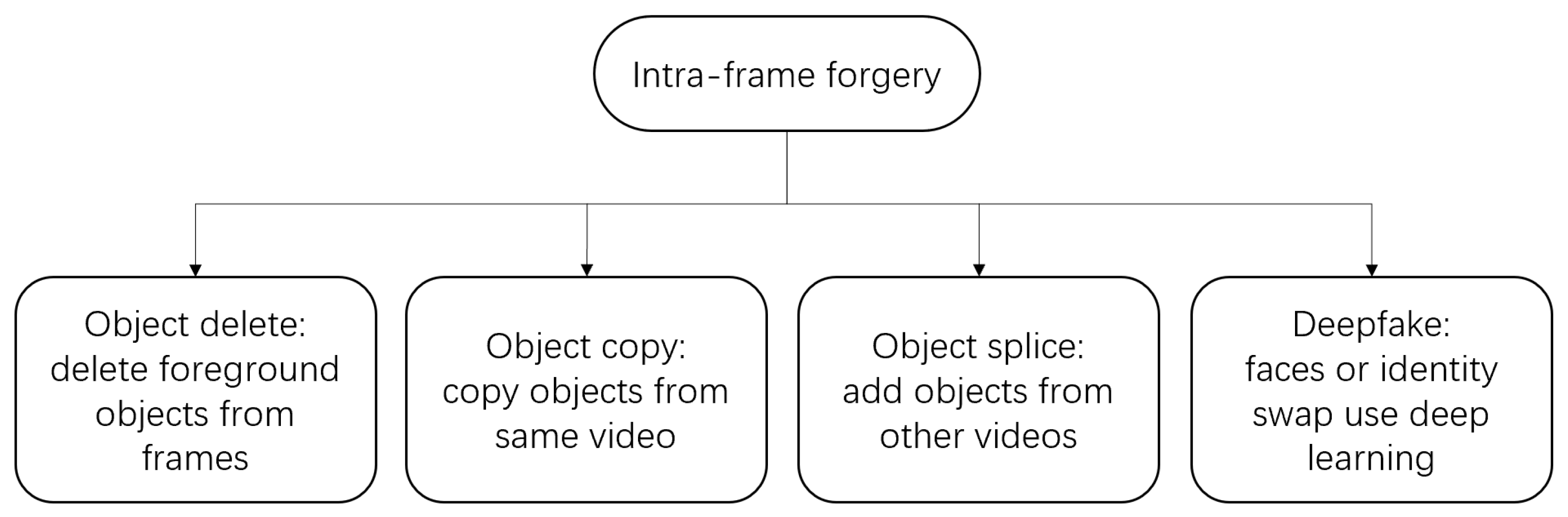
The forgery operations for digital video can be divided into two groups: inter-frame forgery [1,2] and intra-frame forgery [3]. Intra-frame forgery detection is the main research content of this paper. The intra-frame modification of moving objects is usually the most concerning malicious tampering and forgery operation. In particular, the change of semantic video objects directly affects people’s understanding and cognition of video content, such as the deletion or splicing of moving objects. A description of different types of object-based intra-frame forgery operations is summarized in Figure 1.
Video splicing refers to copying some regions of one video, especially foreground objects, into another video, which is one of the most common object-based intra-frame tampering operations in digital video. This operation completely changes the semantic information of the original video content, destroying the authenticity of the video. In this paper, we mainly focus on the detection of video splicing.
According to the characteristics of a video splicing operation, the synthesized video is spliced using two different videos, and the forged video contains equipment information from two different cameras. Therefore, features that can identify device information are often used to detect forgery, such as sensor pattern noise (SPN). Because of the non-ideality of the imaging sensor, each digital camera outputs a relatively stable residual noise, which is called camera sensor pattern noise [4]. SPN mainly refers to the photo-response non-uniform (PRNU), which is mainly produced by the pixel inhomogeneity of the sensor, that is, the main component is the pixel non-uniform. SPN not only varies from camera to camera but also follows a consistent pattern for every image or video frame recorded by a particular camera. Therefore, it can be regarded as a camera fingerprint. This noise information is added to the image data of each frame of the video and can be used to track the source camera as well as detect content forgery.
The use of SPN in video forensics is mainly focused on source camera identification [5,6] and video recapture [7,8]. Some scholars have also tried to detect video content forgery based on pattern noise, such as object deletion, copy-paste, video splicing, and so on. For video object deletion forgery, Hsu et al. [9] detected the consistency of noise residual correlation to determine whether the video motion object was deleted. Hyun et al. [10] use SPN to detect tampering operations such as video clipping or object deletion for surveillance video. Sun et al. [11] illustrated a scheme to recognize video object deletion forgery based on pattern noise consistency. The scheme in Ref. [12] combines SPN and noise residual inconsistency to detect and locate the object deletion region. For video copy-paste forgery, Liu et al. [13] proposed a method based on a noise correlation matrix to realize the detection of video copy-paste forgery. Raahat et al. [14] pointed out that SPN was much more robust and efficacious than noise residue and proposed a copy-paste tamper detection method based on SPN. The Hausdorff distance-based clustering scheme is used to detect and locate the copy-paste region. For video splicing forgery, Kobayashi et al. [15] were dedicated to detecting synthesized videos based on inconsistency in NLF (noise level function). Assuming that the NLF generated by the camera’s response function is linear, the noise characteristic at each pixel can be obtained. However, this method is not suitable for nonlinear NLF. A detection algorithm for blue screen matting and synthetic tampering is proposed in Ref. [16]. A reference pattern of noise for a digital camera is extracted by averaging the residual noise from each video frame. The forgery can be exposed in the Fourier transform domain via the difference between the noise pattern of the original video and that of the forged video. However, the algorithm assumes that the matting foreground image comes from a high-resolution camera. When the assumption condition is not satisfied, the detection accuracy decreases. Huang et al. [17] proposed a forgery detection method based on pattern noise clustering analysis. The objects in low-density regions are obtained via a density-based clustering algorithm, which considers tampered areas.
In recent years, video splicing detection has been paid more attention by researchers. Su et al. [18] extracted quantized DCT coefficients of the foreground and background respectively according to different quantization scale factors. The difference between the two distribution coefficients was analyzed to determine whether the video was composed of blue screen images. Chen et al. [19] utilized the statistical characteristics of video objects, such as the moment features of wavelet coefficients and the average gradient of each color channel, to determine the classification of natural objects and those that have been spliced. Yuan et al. [20] detected the edge of the video frame using the Sobel operator and computed the deviation of four directions to judge a suspicious object edge. Liu et al. [21] proposed a foreground detection and tracking scheme to identify blue screen compositing. Local features like luminance and contrast are fused to find the tampered foreground block, and the forged block is tracked in subsequent frames. Jin et al. [22] adopted discontinuous noise distribution and video object segmentation contours as traces to detect the splicing operation.
With the development of deep learning technology, deep learning-based forgery operations are becoming more and more mature; a quintessential application is deepfake. At the same time, deep learning technology has also been applied to forgery detection methods, such as camera model identification [23], image recapture forensics [24], video inter-frame forgery detection [25], and video intra-frame forgery detection [26]. Yao et al. [27] employed CNN (convolutional neural network) to automatically extract high-dimension features to detect object-based forgery. Cozzolino et al. [28] used the Siamese network to extract camera model fingerprints for the detection and localization of image forgery. Based on this work, they applied the technique to video splicing forensics [29]. A Siamese network that enhances the model-related traces hidden in a video is trained, and the pixel-correlation inspection with noise inconsistency is selected. The method is also suitable for deepfake forgery detection, similar to face swapping. Jung et al. [30] utilized DeepVision to analyze significant changes in the eye blinking pattern to detect deepfakes generated by GAN (generative adversarial network). The measurements are compared with DeepVision’s natural motion database to distinguish deepfakes from a normal video. Wang et al. [31] picked out AI-synthesized fake faces using FakeSpotter. The capabilities of neurons to monitor layer-by-layer behaviors can capture more subtle differences to classify real or fake faces.
According to the analysis of the above references, the SPN-based method can effectively detect video tampering operations, but these algorithms still have some drawbacks. Firstly, the camera reference sensor pattern noise (RSPN) is usually estimated by averaging the noise of all frames in the video. However, the splicing forgery will change the uniformity of the pattern noise. On the other hand, when locating the forged area, the entire video frame is usually calculated, without considering the semantic content of the video frame, which not only consumes time but also affects the positioning accuracy. Therefore, how to improve the quality of the estimated camera RSPN and the accuracy of locating is very important. In this paper, we present an effective video splicing detection algorithm based on SPN. By analyzing the correlation of the SPN, we can identify whether the video has been tampered with and locate the forged region. The experimental results show that the detection accuracy is improved by enhancing the quality of the extracted RSPN. The main contributions of our work are summarized as follows.
- (1)
- Focus on the region of interest in the video is achieved. As the embodiment of the semantic content of the video, the foreground object is usually spliced into other videos. The contours of foreground objects are used to guide the precise recognition of object-based splicing forgery, and the detection results are not affected even if the video contains multiple foreground objects.
- (2)
- Combining the video noise fingerprint with the video region of interest, only the background frames of the video are used to estimate the camera RSPN. The noise interference caused by spliced foreground objects is eliminated, and the quality of the estimated camera RSPN is improved.
2. Materials and Methods
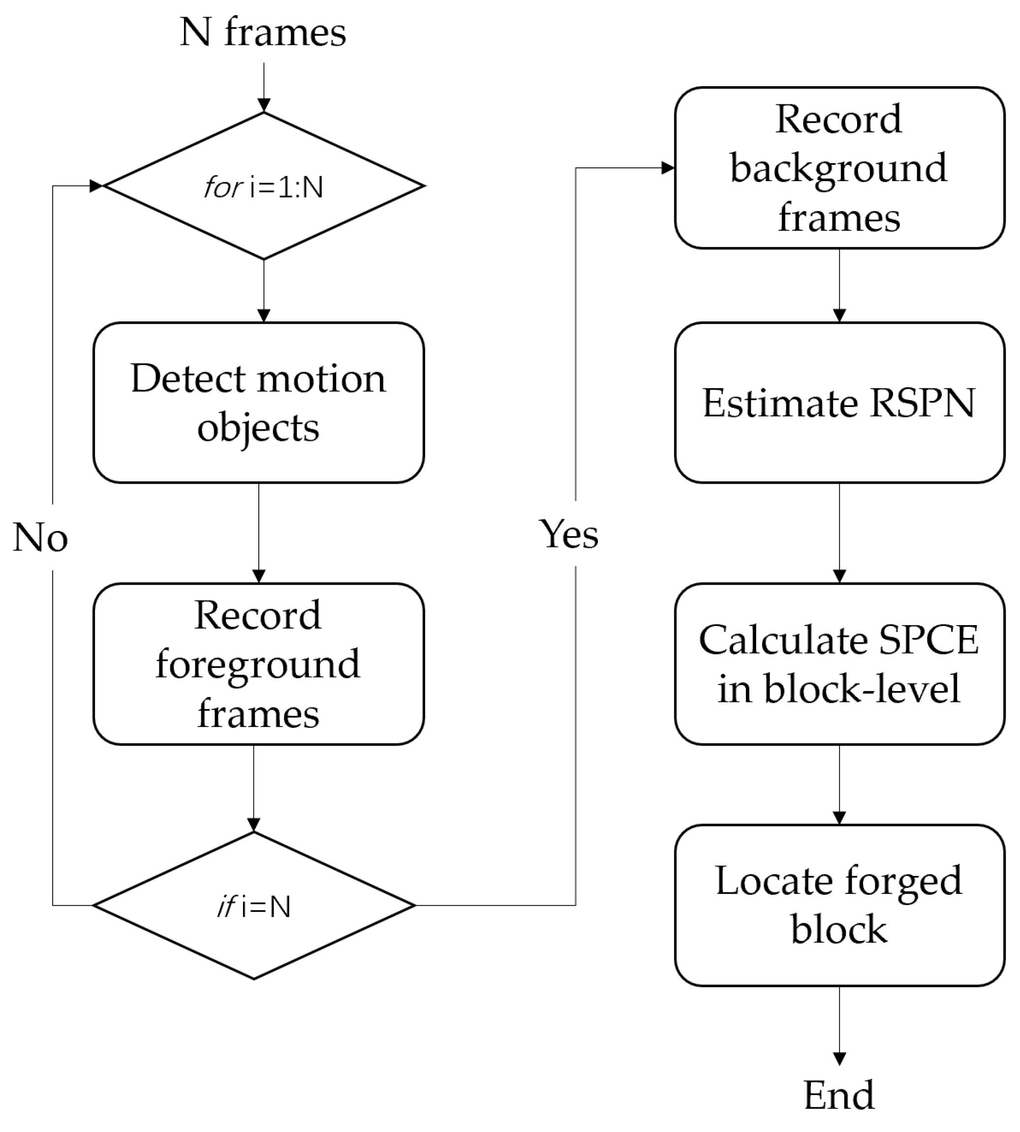
In the previous algorithms, the RSPN is usually extracted by averaging the noise of all frames in the video. But due to the splicing video being a composite of two different videos, if all frames of the splicing video are used to establish the RSPN, the different SPN in the video will reduce the consistency of the noise model and affect the detection accuracy. Assuming that video Q is the original background video and video R is the original foreground video containing moving objects, video C is obtained by compositing video Q and video R. To improve the quality of the RSPN of the video, it is necessary to distinguish the SPN of video Q and video R. Since the original videos cannot be obtained in practical application, it is necessary to preprocess the test video, video C, to achieve an approximate effect. The extraction steps of RSPN for test video C are as follows.
Step 1: Detect the moving objects in the test video and record the frames which contain the moving objects into the set M, ; n is the number of video frames containing moving objects.
Step 2: Record the other frames which do not contain moving objects into set S, ; j is the number of video frames without moving objects.
Step 3: The RSPN of the test video is obtained using the frames in set S.
The RSPN estimated by set S can eliminate the interference of the spliced foreground objects. The correlation with the original object is enhanced, and the correlation with the forged object is reduced, thus effectively distinguishing the forged object from the original object.
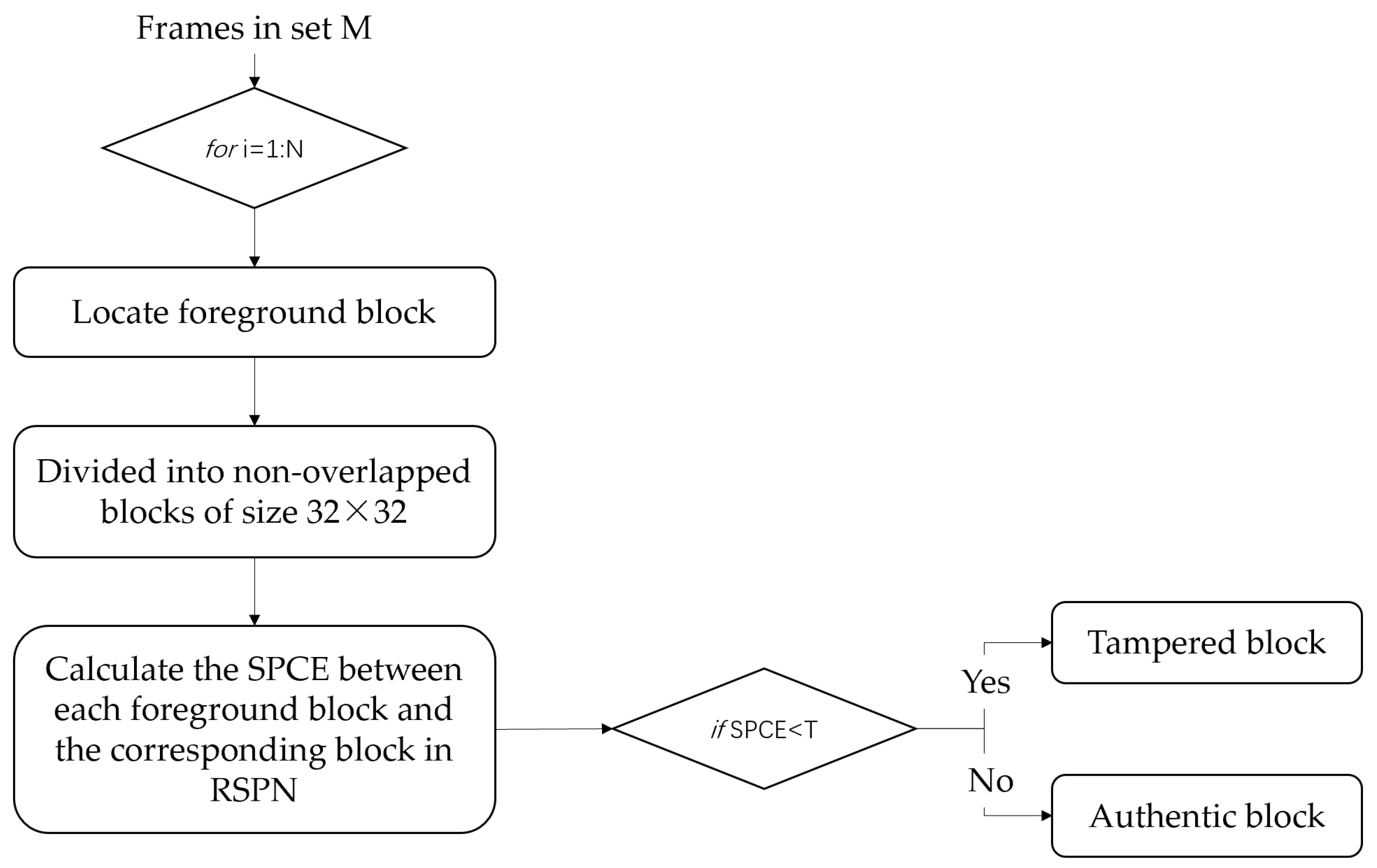
The flowchart of the algorithm is shown in Figure 2.
2.1. Motion Objects Detection
Background subtraction is a common method in the segmentation of moving objects. It detects moving regions by calculating the difference between the current image and the background image. The algorithm needs to get the background model of the scene first and then use foreground detection to obtain the foreground. Since the accuracy of the background model directly affects the detection results of moving targets, researchers have proposed a variety of models. The most widely used is the Gaussian mixture model (GMM) [32,33], which is used to extract the foreground objects of the video frame. This model solves two problems: one is the change in the background, which refers to the change brought by adding or removing the objects to the background, the change of color and shadow caused by light, etc. The GMM can be used to inform the background of the change in real-time by updating each frame, to avoid the error of target detection. Another problem is the movement in the background, such as the fluttering of leaves and flags. By using the GMM, we can judge that these movements belong to the background rather than the foreground. The following is a brief introduction to the moving objects detection method used in this paper.
GMM uses K Gaussian models (usually 3–5) to characterize the features of each pixel in the image and updates the Gaussian mixture model after the new frame is obtained. Based on the mean and variance of each Gaussian function in the mixture model, it is possible to determine which model corresponds to the background. Those pixels that do not conform to the background model are considered foreground points.
For RGB images, assume that the pixels in R, G, and B channels are independent of each other and have the same covariance matrix. At any time t, the probability density function of the mixture Gaussian distribution of the single sampling point can be given using (1).
where K is the number of Gaussian functions of a pixel, and is the weight of the ith Gaussian function in the mixture at the time t. η(⋅) represents the Gaussian function with mean μ and variance σ. τ is the covariance matrix, , and I is the unit matrix. The expression of the Gaussian function is as follows:
where n is the dimension of ; the value of n is 1 for the gray image and 3 for the color image.
The value of each pixel is matched with the existing K Gaussian distributions according to Equation (3) until a distribution model matching the new pixel is found, that is, it is within 2.5 times the standard deviation from the mean.
If none of the Gaussian distributions match the current pixel value, the distribution with the lowest priority () is removed and a new distribution is introduced, the mean of which is , with low weight and high variance. All Gaussian models are arranged in descending order of priority. The first B models are usually used to represent the background.
where θ is the threshold to measure which models should be classified as background, .
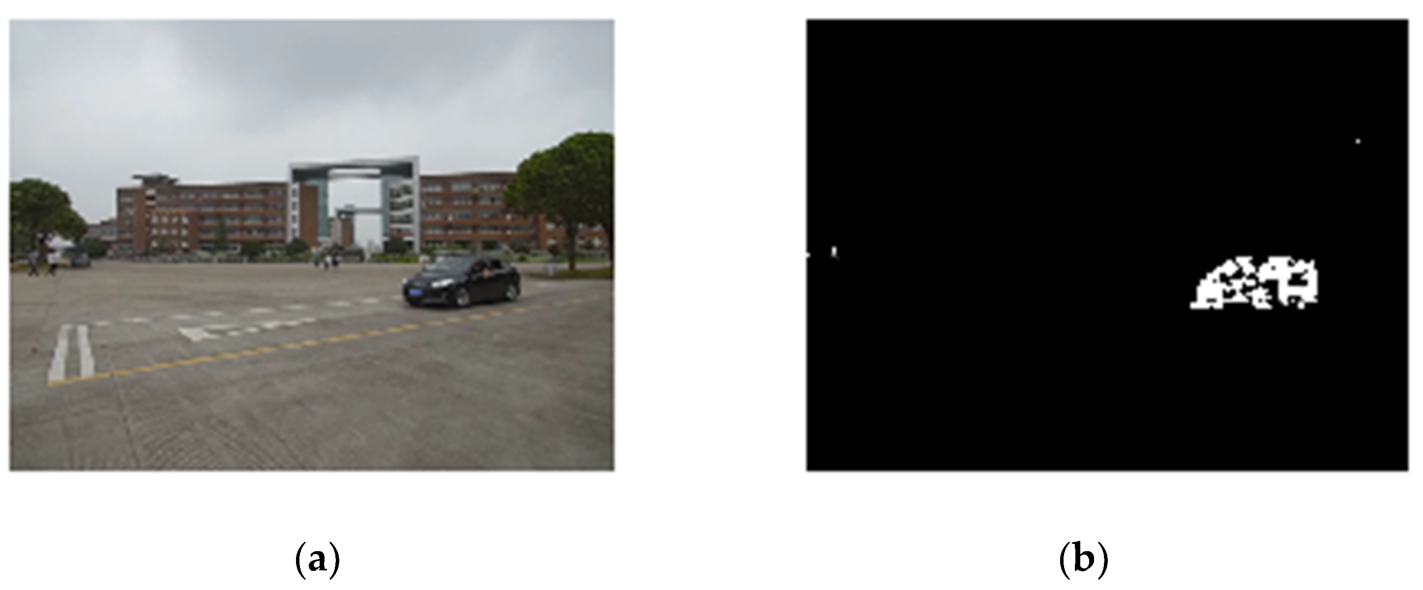
The pixel belongs to the background if the matched model meets the background requirements, otherwise, it belongs to the foreground. The morphological operation function is used to post-process the detected foreground, which removes the isolated small points in the image and fills in the small holes, but the position and shape are unchanged. A sample of the moving object detection result is shown in Figure 3, and the white area represents the foreground. The frame number which contains moving objects is recorded into set M, and the coordinates and the size of the moving objects are recorded. The sequence numbers of other frames without moving objects are recorded into set S.
2.2. Reference Sensor Pattern Noise Extraction
To obtain the RSPN of the video, the noise residuals of a single frame should be extracted first. We extracted the noise residuals from the three color channels of RGB images. Li et al. [34] pointed out that the noise residuals extracted from three color channels separately can eliminate the effect of CFA interpolation. Image I is de-noised to obtain the denoising image F(I), and F is the denoising filter. A noise residual W of an image can be obtained as follows.
where K represents the real SPN of the camera, namely, the camera fingerprint, whose main component is PNU (IK). Θ is the synthesis of other noise in the image, which is independent of IK, including dark noise, readout noise, quantization noise, and so on. Using the noise residuals of multiple images will suppress the random noise and enhance the PNU. The RSPN of the video can be obtained by using the maximum likelihood estimation method.
where N is the number of frames, and the frames are from set S.
To improve the quality of RSPN, further post-processing operations are performed. Zero-mean (ZM) and wiener filtering (WF) are used to eliminate the interference of random noise such as CFA interpolation noise and block effect brought by compression for each color channel. Then, notch filtering is used in the Fourier domain to eliminate the influence of periodic signals.
To verify the quality of the extracted RSPN, the method was tested on forged videos. The RSPN of the test video was extracted using Ref. [16] and the method in this paper respectively. The RSPN in Ref. [16], named RSPN_all, is estimated using all frames of the video, and the RSPN in this paper, named RSPN_bg, is estimated using the video frames without moving objects. To guarantee fairness, the same post-processing operations were used in both methods.
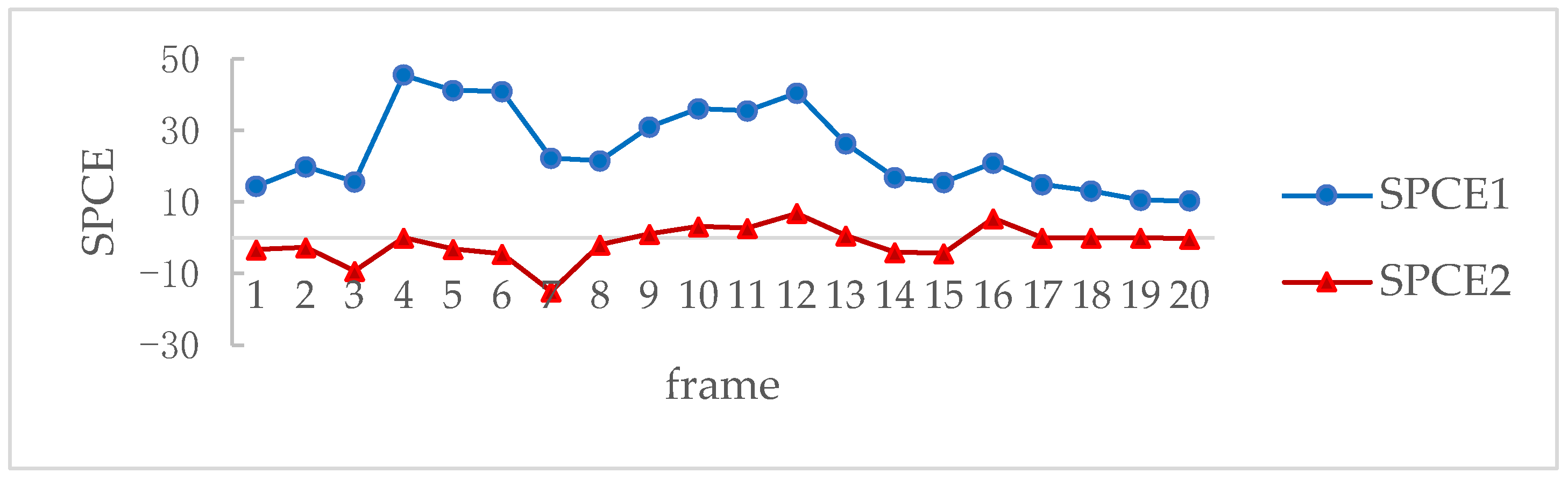
A total of 40 frames of the test video were randomly selected to calculate the correlation between the current frame and the RSPN, of which 20 frames were from set M and 20 frames were from set S. A signed peak-to-correlation energy (SPCE) method [35] is proposed to measure the correlation of two images.
where P is the correlation function of W and R (m × n), and its dimension is the same as W and R. Pmax is the peak of P. sign (Pmax) is the signed peak. The denominator is the mean of the sum of squares of points outside the N × N region centered on Pmax.
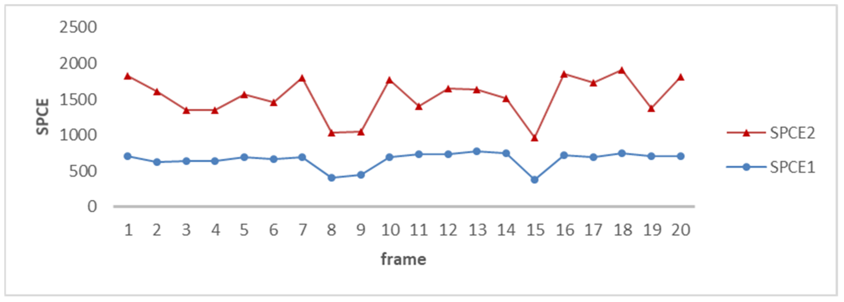
The correlation between the frames of the test video and RSPN_all and RSPN_bg was calculated respectively and recorded as SPCE1 and SPCE2. For normal areas, the higher the SPCE value, the better the quality of the RSPN. However, in the tampered area, the lower the value of the SPCE, the better the quality of the RSPN. Figure 4 shows the values of SPCE between the normal video frames and the RSPN. It can be seen that the values of SPCE2 are generally larger than SPCE1.
To accurately describe the correlation between the tampered area and the RSPN, we calculated the SPCE on the block level, which only calculates the SPCE value of the synthesized moving objects area. Figure 5 shows the SPCE values between the forged area and the counterpart block of RSPN; the values of SPCE2 are generally less than SPCE1. From Figure 4 and Figure 5, we can see that the proposed scheme can obtain high-quality RSPN.
2.3. Forgery Detection
This algorithm focuses on detecting whether there are synthesized moving objects in the test video, so the moving objects are the region of interest of the algorithm. The correlation between the SPN of test frames and the RSPN of the test video can be calculated at the block level to determine whether the moving objects are true or not. A flowchart is shown in Figure 6, and the steps are as follows.
Step 1: Record the coordinates and the size of each moving object of each video frame in set M.
In the process of detecting moving objects in Section 2.1, the pixels in the foreground have been marked. Thus, there is no extra computation involved in this step.
Step 2: The SPCE between the SPN in the pixel area of the moving objects and the RSPN in the corresponding pixel of the test video is calculated.
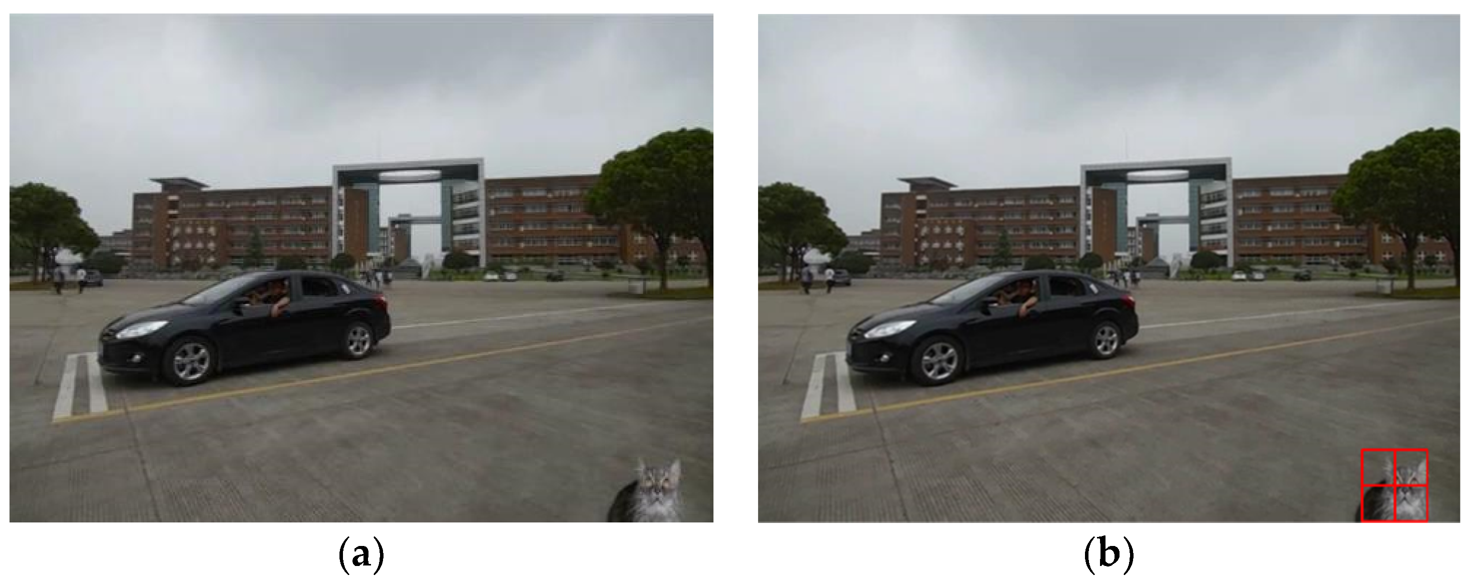
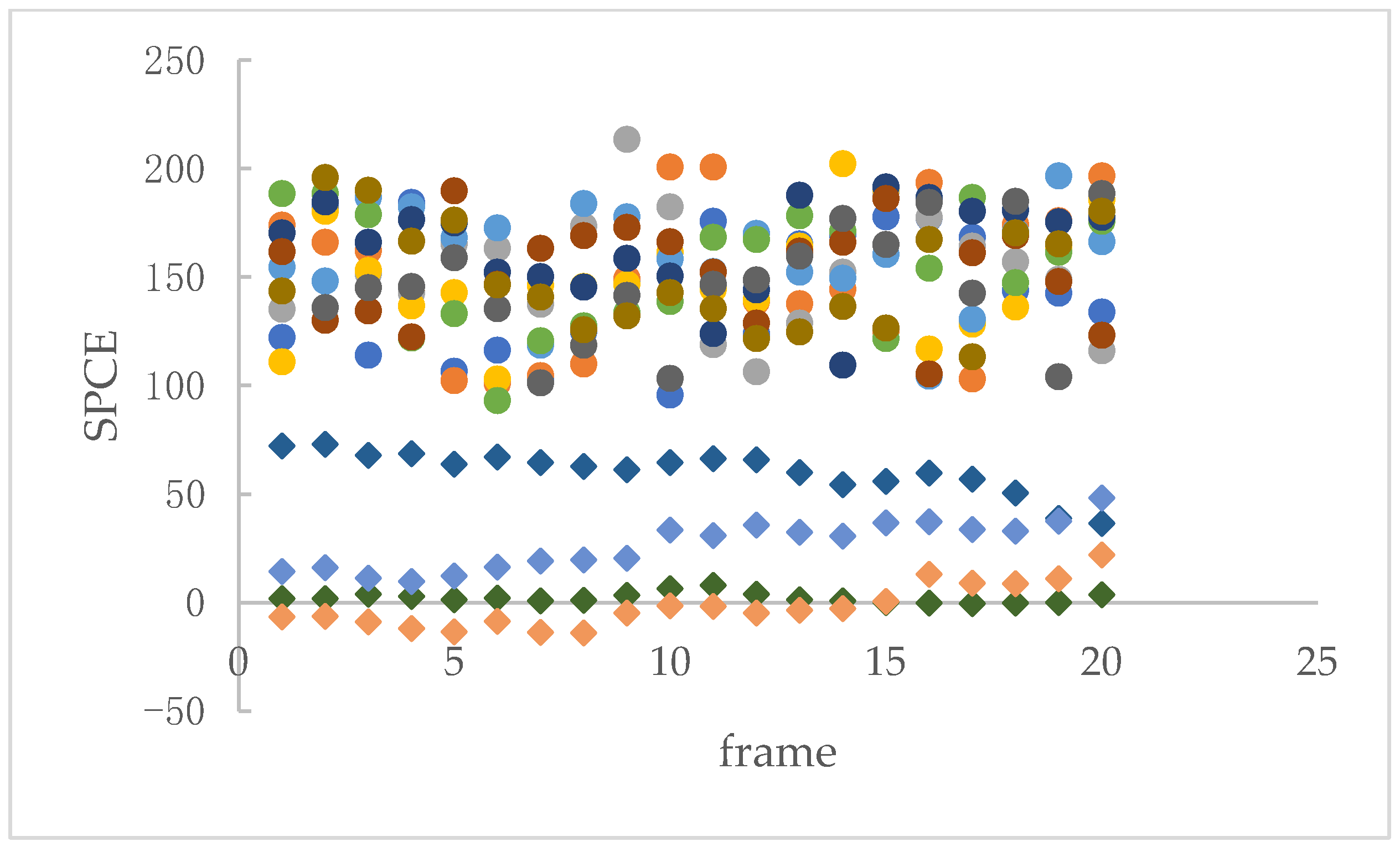
For example, in Figure 7, the test video “SAM_3.mov” is a heterologous splicing video, where the car is the original moving object and the cat is the splicing object. A total of 20 frames containing moving objects are tested. The regions of the moving objects are divided into non-overlapped blocks of size 32 × 32 and calculate the SPCE between each block and the corresponding RSPN. The results are shown in Figure 8; the tampered object can be distinguished via the distribution trend of the SPCE values.
Step 3: Record the areas where the SPCE value is lower than the threshold and locate forged objects.
Figure 8 shows that most of the SPCE values of the non-tampered areas are above 100, while most of the SPCE values of the tampered areas are concentrated around 0. By setting a reasonable threshold, we can distinguish whether the detection object is forged.
3. Results
To verify the effectiveness of the algorithm, the algorithm was tested on the Matlab R2018b platform. The computer configurations are as follows:
- CPU: Intel Core i7-6500U CPU @ 2.50 GHz 2.50 GHz;
- RAM: 8.00 GB;
- OS: Windows 10 Professional 64-bit.
3.1. Video Database
In our experiments, videos of different sources and resolutions were selected, and the information from the video database is shown in Table 1. GRIP [36] and HTVD [37] are publicly available datasets, which consist of 10 splicing videos, respectively. Camera videos are taken from six digital cameras with a resolution of 640 × 480; the frame rate is 29 fps. Guo et al. [38] verified that the value of SPCE increases with the increase of image texture complexity. Therefore, the video content captured in this article contains different texture complexities and different numbers of foreground objects.
- (1)
- Original video samples. Six cameras capture 90 original videos containing moving objects and each video is 30 s.
- (2)
- Foreground object samples. Three cameras are used to capture 6 video clips containing foreground objects, and each video is 10 s.
- (3)
- Forged video samples. Another three cameras are used to take background videos and each video is 30 s. Combining foreground moving objects and background videos from different cameras, 90 forged videos are obtained.
3.2. Experimental Steps
Step 1. Moving object detection was performed on the test video, and the sequence number of the frame containing the moving object as well as the coordinate and size of each moving object in each frame were recorded for the convenience of subsequent calculation.
Step 2. The frameset without moving objects was used to estimate the RSPN of the video. Removing frames containing foreground objects can eliminate the interference of foreground objects and improve the extraction quality of RSPN.
Step 3. The correlation SPCE between the region of the moving object in each frame and the corresponding region of the RSPN was calculated at the block level. The calculation region was divided into non-overlapped blocks of size 32 × 32. Block-level computation can improve the robustness of the algorithm to adapt the size of the tampered area.
Step 4. The block with SPCE less than the threshold T was recorded as a tampered block; otherwise, the block was recorded as the original block. Frames that contain tampered blocks are considered tampered frames, and the videos that contain tampered frames are considered tampered videos.
In order to improve the accuracy of the algorithm, we did post-processing operations on the detection results. A single exception block in a frame was ignored; an exception refers to the detection results being different from other blocks in the frame. This is because the edge blocks of moving objects are affected by the surrounding pixels, leading to deviation of the detection result.
3.3. Evaluation Metrics
To effectively evaluate the performance of the algorithm, this paper introduces four objective evaluation indexes, namely, Recall, Precision, F1-score, and Accuracy.
Recall refers to the percentage of true positive samples out of all positive samples; Precision represents the proportion of true positive samples among all samples that are classified as positive; F1-score is the weighted average of Recall and Precision; Accuracy indicates the average detection accuracy.
where TP (true positive) is the correct number of positive samples, that is, tampered video is detected as tampered video; TN (true negative) is the correct number of negative samples, that is, the normal video is detected as normal video; FP (false positive) is the wrong number of positive samples; FN (false negative) is the wrong number of negative samples; (TP + FN) is the total number of tampered videos; (TP + FP) is the total number of videos classified as forged; (TP + FP + TN + FN) is the total number of the dataset.
4. Experimental Results and Discussion
We tested the proposed algorithm on the database mentioned in Section 3.1 and compared our results with those reported in [21,22,29]. To guarantee fairness, we trialed these approaches on the same dataset and applied the parameters suggested by the algorithm. The statistical data of the test results are given in Table 2.
It can be seen from Table 2 that our method has the highest F1 and accuracy among the four algorithms. In order to verify that the detection results of the proposed method are not affected by the foreground moving objects, the database we used contains different texture complexities and different numbers of foreground objects. When there is no foreground interference, the accuracy of the reference [21] method is good. However, the accuracy is slightly reduced in the presence of foreground interference. In Reference [22], the movement size of the method is related to the movement speed of the spliced object. The detection accuracy is affected by the use of uniform movement size in the database. Reference [29] trained the video noiseprint extractor primarily through I-frames and is appropriate for H.264 compressed format only.
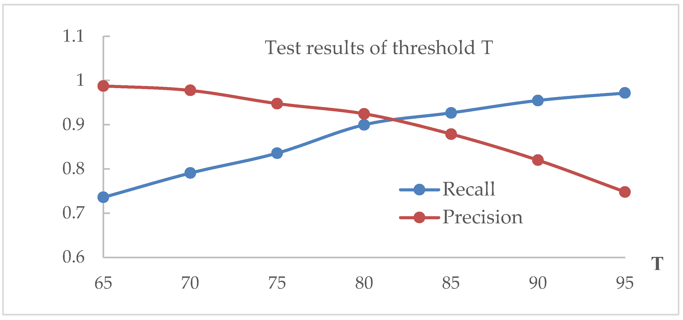
In the experiment, we used threshold T = 80 in Section 3.2. T is an experience threshold that distinguishes authentic foreground blocks from fake blocks. In this section, recall and precision are used to select an appropriate threshold. The higher the recall rate, the lower the omission coefficient of the algorithm. The higher the precision value, the lower the false detection rate of the algorithm.
Figure 9 shows the test results under different threshold values T. The vertical axis is the value of recall and precision, and the horizontal axis denotes the value of T. As can be seen from Figure 9, when T decreases, recall decreases and precision increases, but it is opposite when T increases. This is because the lower the threshold, the greater the risk that the forgery will be identified as genuine; the higher the threshold, the greater the risk that the real video will give the result of a forgery. We set T = 80 to achieve a balance between recall and precision.
5. Conclusions
In this paper, we proposed a video splicing detection scheme based on SPN. The method consists of detecting moving objects, estimating RSPN, and calculating SPCE. By improving the extraction quality of RSPN, the algorithm achieves a good detection effect.
Firstly, the foreground objects of the frame are extracted using GMM, and the frame number is recorded. Then, when training the RSPN of the video, we culled the frames containing foreground objects, so the interference of foreground objects in the detection results is eliminated and the robustness of the algorithm is improved. Finally, the SPCE is calculated at the block level to measure the correlation between the SPN of the foreground blocks and the RSPN of the corresponding region. By setting a reasonable threshold, we can distinguish forged objects from normal objects, even if there are multiple forged objects. The experimental results show that the method can accurately locate the forged region and has higher recall and precision compared with other forensics algorithms.
There are still some limitations in this work, such as when locating forged objects, if the tampered area is too small, it may also lead to missed detection, although block-level computation was used to improve the robustness of the algorithm to adapt the size of the tampered area. In addition, if all the video frames contain foreground objects, the detection method is impossible. In future work, we will focus on finding other technologies to solve these problems. For example, by combining deep learning techniques to learn the statistical characteristics of the contours of foreground objects, it is possible to improve the accuracy of identifying the tiny splicing regions.
Author Contributions
Q.L., R.W. and D.X. discussed and designed the forgery detection method. Q.L. designed and implemented the detection algorithm, D.X. tested and analyzed the experimental results, and R.W. thoroughly reviewed and improved the paper. All authors have discussed and contributed to the manuscript. All authors have read and agreed to the published version of the manuscript.
Funding
This research was funded by Zhejiang Provincial Natural Science Foundation of China (Grant No. LQ20F020025), Natural Science Foundation of Ningbo (Grant No. 202003N4073).
Data Availability Statement
The data used to support the findings of this study are available on request from the corresponding author.
Acknowledgments
We thank our study participants and gratefully acknowledge support from the research fund.
Conflicts of Interest
The authors declare no conflict of interest.
References
- Fadl, S.; Han, Q.; Qiong, L. Exposing video inter-frame forgery via histogram of oriented gradients and motion energy image. Multidimens. Syst. Signal Process. 2020, 31, 1365–1384. [Google Scholar] [CrossRef]
- Kumar, V.; Gaur, M. Multiple forgery detection in video using inter-frame correlation distance with dual-threshold. Multimed. Tools Appl. 2022, 81, 43979–43998. [Google Scholar] [CrossRef]
- Shelke, N.A.; Kasana, S.S. Multiple forgery detection and localization technique for digital video using PCT and NBAP. Multimed. Tools Appl. 2022, 81, 22731–22759. [Google Scholar] [CrossRef]
- Lukáš, J.; Fridrich, J.; Goljan, M. Detecting digital image forgeries using sensor pattern noise. Proc. Soc. Photo-Opt. Instrum. Eng. Conf. 2006, 6072, 362–372. [Google Scholar]
- Lee, S.H.; Kim, D.H.; Oh, T.W.; Kim, K.B.; Lee, H.Y. Digital Video Source Identification Using Sensor Pattern Noise with Morphology Filtering. KIPS Trans. Softw. Data Eng. 2017, 6, 15–22. [Google Scholar] [CrossRef] [Green Version]
- Orozco, A.L.S.; Huamán, C.Q.; Quintero, J.A.C.; Villalba, L.J.G. Digital Video Source Acquisition Forgery Technique Based on Pattern Sensor Noise Extraction. IEEE Access 2019, 7, 157363–157373. [Google Scholar] [CrossRef]
- Jung, D.J.; Hyun, D.K.; Lee, H.K. Recaptured video detection based on sensor pattern noise. EURASIP J. Image Video Process. 2015, 2015, 40. [Google Scholar] [CrossRef] [Green Version]
- Mehta, P.; Maheshkar, S.; Maheshkar, V. An Effective Video Bootleg Detection Algorithm Based on Noise Analysis in Frequency Domain. Int. Conf. Comput. Vis. Image Process. Commun. Comput. Inf. Sci. 2020, 1147, 227–238. [Google Scholar]
- Hsu, C.C.; Hung, T.Y.; Lin, C.W.; Hsu, C.T. Video forgery detection using correlation of noise residue. In Proceedings of the 2008 IEEE 10th Workshop on Multimedia Signal Processing, MMSP 2008, Cairns, Australia, 8–10 October 2008; pp. 170–174. [Google Scholar]
- Hyun, D.K.; Lee, M.J.; Ryu, S.J.; Lee, H.-Y.; Lee, H.-K. Forgery detection for surveillance video. Era Interact. Media 2013, 25–36. [Google Scholar] [CrossRef]
- Kejian, S. Detecting Forgery from Video with Pattern Noise Consistency. Master’s Thesis, China University of Mining & Technology, Xuzhou, China, 2014. [Google Scholar]
- Fayyaz, M.A.; Anjum, A.; Ziauddin, S.; Khan, A.; Sarfaraz, A. An improved surveillance video forgery detection technique using sensor pattern noise and correlation of noise residues. Multimed. Tools Appl. 2020, 79, 5767–5788. [Google Scholar] [CrossRef]
- Liu, Y. Research on Video Source Identification and Forgery Detection Method for Video Monitoring System. Master’s Thesis, Xidian University, Xi’an, China, 2020. [Google Scholar]
- Singh, R.D.; Aggarwal, N. Detection and localization of copy-paste forgeries in digital videos. Forensic Sci. Int. 2017, 281, 75–91. [Google Scholar] [CrossRef]
- Kobayashi, M.; Okabe, T.; Sato, Y. Detecting forgery from static-scene video based on inconsistency in noise level functions. IEEE Trans. Inf. Forensics Secur. 2010, 5, 883–892. [Google Scholar] [CrossRef]
- Guo, L.; Zhang, J.; Su, Y. A chroma keying video forgery detection algorithm based on sensor noise. J. Sichuan Univ. (Nat. Sci. Ed.) 2011, 48, 777–782. [Google Scholar]
- Huang, T.; Wu, T.; Yuan, X.; Chen, Z. Detecting Video’s Authenticity Based on Video Pattern Noise Clustering Analysis. J. Front. Comput. Sci. Technol. 2011, 5, 914–920. [Google Scholar]
- Xu, J.; Yu, Y.; Su, Y.; Dong, B.; You, X. Detection of Blue Screen Special Effects in Videos. In Proceedings of the International Conference on Medical Physics and Biomedical Engineering (ICMPBE), Singapore, 12–14 September 2012; pp. 1316–1322. [Google Scholar]
- Richao, C.; Gaobo, Y.; Ningbo, Z. Detection of object-based manipulation by the statistical features of object contour. Forensic Sci. Int. 2014, 236, 164–169. [Google Scholar] [CrossRef]
- Yuan, X.; Huang, T.; Su, L.; Chen, Z.; Wu, T. Detection of Video Matting Tamper Based on Edge Anomaly and Compressive Tracking. Comput. Eng. 2014, 40, 267–276. [Google Scholar]
- Liu, Y.; Huang, T.; Liu, Y. A novel video forgery detection algorithm for blue screen compositing based on 3-stage foreground analysis and tracking. Multimed. Tools Appl. 2018, 77, 7405–7427. [Google Scholar] [CrossRef]
- Jin, X.; He, Z.; Xu, J.; Wang, Y.; Su, Y. Video splicing detection and localization based on multi-level deep feature fusion and reinforcement learning. Multimed. Tools Appl. 2022, 81, 40993–41011. [Google Scholar] [CrossRef]
- Bondi, L.; Baroffio, L.; Güera, D.; Bestagini, P.; Delp, E.J.; Tubaro, S. First Steps Toward Camera Model Identification with Convolutional Neural Networks. IEEE Signal Process. Lett. 2017, 24, 259–263. [Google Scholar] [CrossRef] [Green Version]
- Yang, P.; Ni, R.; Zhao, Y. Recapture Image Forensics Based on Laplacian Convolutional Neural Networks. In Proceedings of the 15th International Workshop on Digital Forensics and Watermarking (IWDW), Beijing, China, 17–19 September 2016; pp. 119–128. [Google Scholar]
- Kaur, H.; Jindal, N. Deep Convolutional Neural Network for Graphics Forgery Detection in Video. Wirel. Pers. Commun. 2020, 112, 1763–1781. [Google Scholar] [CrossRef]
- Jin, X.; He, Z.; Wang, Y.; Yu, J.; Xu, J. Towards general object-based video forgery detection via dual-stream networks and depth information embedding. Multimed. Tools Appl. 2022, 81, 35733–35749. [Google Scholar] [CrossRef]
- Yao, Y.; Shi, Y.; Weng, S.; Guan, B. Deep Learning for Detection of Object-Based Forgery in Advanced Video. Symmetry 2018, 10, 3. [Google Scholar] [CrossRef] [Green Version]
- Cozzolino, D.; Verdoliva, L. Noiseprint: A CNN-based camera model fingerprint. IEEE Trans. Inf. Forensics Secur. 2020, 15, 144–159. [Google Scholar] [CrossRef] [Green Version]
- Davide, C.; Giovanni, P.; Luisa, V. Extracting camera-based fingerprints for video forensics. In Proceedings of the IEEE Conference on Computer Vision and Pattern Recognition Workshops, Long Beach, CA, USA, 16–17 June 2019; pp. 130–137. [Google Scholar]
- Jung, T.; Kim, S.; Kim, K. DeepVision: Deepfakes Detection Using Human Eye Blinking Pattern. IEEE Access 2020, 8, 83144–83154. [Google Scholar] [CrossRef]
- Wang, R.; Juefei-Xu, F.; Ma, L.; Xie, X.; Huang, Y.; Wang, J.; Liu, Y. FakeSpotter: A simple yet robust baseline for spotting AI-synthesized fake faces. In Proceedings of the Twenty-Ninth International Joint Conference on Artificial Intelligence (IJCAI), Yokohama, Japan, 11–17 July 2020; pp. 3444–3451. [Google Scholar]
- Stauffer, C.; Grimson, W.E.L. Learning patterns of activity using real-time tracking. IEEE Trans. Pattern Anal. Mach. Intell. 2000, 22, 747–757. [Google Scholar] [CrossRef] [Green Version]
- Zuo, J.; Jia, Z.; Yang, J.; Kasabov, N. Moving Target Detection Based on Improved Gaussian Mixture Background Subtraction in Video Images. IEEE Access 2019, 7, 152612–152623. [Google Scholar] [CrossRef]
- Li, C.T. Source Camera Identification Using Enhanced Sensor Pattern Noise. IEEE Trans. Inf. Forensics Secur. 2010, 5, 280–287. [Google Scholar]
- Goljan, M.; Chen, M.; Comesaña, P.; Fridrich, J. Effect of Compression on Sensor-Fingerprint Based Camera Identification. In Proceedings of the Electronic Imaging, Media Watermarking, Security, and Forensics, San Francisco, CA, USA, 2016, 14–18 February 2016; pp. 1–10. [Google Scholar]
- D’Avino, D.; Cozzolino, D.; Poggi, G.; Verdoliva, L. Autoencoder with recurrent neural networks for video forgery detection. Electron Imaging 2017, 2017, 92–99. [Google Scholar] [CrossRef] [Green Version]
- Singla, N.; Singh, J.; Nagpal, S.; Tokas, B. HEVC based tampered video database development for forensic investigation. Multimed. Tools Appl. 2023, 1. [Google Scholar] [CrossRef]
- Guo, H.; Zhang, R.; Guo, L.; Jiang, B. Image tampering detection and localization algorithm using adaptive thresholding. J. Optoelectron. Laser 2017, 28, 519–528. [Google Scholar]
Figure 1.
Description of different types of intra-frame tamper operations.

Figure 2.
The flowchart of the proposed method.

Figure 3.
The result of moving object detection. (a) Original image; (b) foreground image.

Figure 4.
The values of SPCE between normal video frames and RSPN.

Figure 5.
The values of SPCE between the forged area and RSPN.

Figure 6.
Flowchart of forgery detection.

Figure 7.
One frame of SAM_3.mov. (a) Video frame; (b) detection result. The region in the red box is the splicing object.
Figure 7.
One frame of SAM_3.mov. (a) Video frame; (b) detection result. The region in the red box is the splicing object.

Figure 8.
Distribution of SPCE values in moving objects. The circular symbols represent the SPCE values of the area where the car is located, and the diamond symbols indicate the SPCE values of the area where the cat is located. The horizontal axis represents the frame of the video, while the vertical axis represents the value of SPCE. A total of 20 frames of video were analyzed, in which cars were divided into ten zones represented by circular symbols of different colors, and cats were divided into four zones represented by diamond symbols of different colors.

Figure 9.
The test results of the threshold.


Table 1.
The information of the video database.
| Source | Frame Rate | Resolution | Number of Original Videos | Number of Forged Videos |
|---|---|---|---|---|
| Camera | 29 fps | 640 × 480 | 90 | 90 |
| GRIP | 30 fps | 720 × 1280 | 10 | 10 |
| HTVD | 30 fps | 1980 × 1080 | 10 | 10 |
Disclaimer/Publisher’s Note: The statements, opinions and data contained in all publications are solely those of the individual author(s) and contributor(s) and not of MDPI and/or the editor(s). MDPI and/or the editor(s) disclaim responsibility for any injury to people or property resulting from any ideas, methods, instructions or products referred to in the content. |
© 2023 by the authors. Licensee MDPI, Basel, Switzerland. This article is an open access article distributed under the terms and conditions of the Creative Commons Attribution (CC BY) license (https://creativecommons.org/licenses/by/4.0/).
Share and Cite
MDPI and ACS Style
Li, Q.; Wang, R.; Xu, D. A Video Splicing Forgery Detection and Localization Algorithm Based on Sensor Pattern Noise. Electronics 2023, 12, 1362. https://doi.org/10.3390/electronics12061362
AMA Style
Li Q, Wang R, Xu D. A Video Splicing Forgery Detection and Localization Algorithm Based on Sensor Pattern Noise. Electronics. 2023; 12(6):1362. https://doi.org/10.3390/electronics12061362
Chicago/Turabian StyleLi, Qian, Rangding Wang, and Dawen Xu. 2023. "A Video Splicing Forgery Detection and Localization Algorithm Based on Sensor Pattern Noise" Electronics 12, no. 6: 1362. https://doi.org/10.3390/electronics12061362
Note that from the first issue of 2016, this journal uses article numbers instead of page numbers. See further details here.