
Transmission Performance of Halbach Array Cylindrical Permanent Magnet Governor

1
School of Mechanical Engineering, Anhui Polytechnic University, Wuhu 241000, China
2
Anhui Key Laboratory of Advanced Numerical Control & Servo Technology, Wuhu 241000, China
3
Wuhu Ruilong Robot Technology Co., Ltd., Wuhu 241000, China
*
Author to whom correspondence should be addressed.
†
These authors contributed equally to this work.
Electronics 2023, 12(5), 1161; https://doi.org/10.3390/electronics12051161
Submission received: 4 January 2023
/
Revised: 24 February 2023
/
Accepted: 24 February 2023
/
Published: 27 February 2023
(This article belongs to the Topic Designs and Drive Control of Electromechanical Machines)
Abstract
:A novel cylinder permanent magnet governor (CPMG) with Halbach segmentation is proposed in this paper. In order to improve the transmission performance of the CPMG, different permanent magnet (PM) arrangement methods are adopted. To achieve a fair comparison result, all the PMs are of the same size. The main magnetic fluxes are considered to obtain a comprehensive equivalent magnetic circuit model of the CPMG with Halbach array and analytical output torque that is calculated. The analytical method of transmitted torque for CPMG is then presented. Additionally, the effect of the average output torque of CPMG under parameters of the thickness of the copper rings, the slip rate and the effective coupling of the copper rings are investigated. Finally, the prototype platform is ready for testing on the field. The results were consistent with the results of the simulation, and the error was kept within the range of 5%. This research can provide a theoretical and practical reference for the optimal design of the transmission characteristic of CPMG.
1. Introduction
As a new type of transmission equipment, cylindrical permanent magnet governor (CPMG) has attracted much attention in recent years and is widely used in fan and pump systems [1,2]. Compared to traditional mechanical connections, cylindrical permanent magnet governor (CPMG) uses magnetic field coupling between a motor and a load shaft to transfer torque in the transmission system without any direct mechanical connections, which can produce less mechanical friction with over-torque protection ability as well as soft start through adjusting the coupling ratio between the conductor and magnet [3,4,5]. Unlike an axial permanent magnet governor, CPMG is a simple structure with fewer axial forces during operation. The permanent magnet governor operates in noncontact mode, which avoids vibration operation.
In recent years, many researchers have carried out a series of studies on permanent magnet governors. A large number of researchers are dedicated to the analysis and design optimization of the PMG with 2D and 3D FEA [6,7,8,9,10,11]. These works provide ideas on how to select meshing for FEA models, reduce numerical errors, selection of design parameters and constraints for the optimization process. Taqavi Omolbanin has calculated flux densities in different parts of the axial-flux permanent magnet machines combining the solution of Maxwell’s equations and the magnetic equivalent circuit (MEC), taking into account the effects of permanent magnet (PM) reluctance, leakage flux between PM-to-PM, PM-to-rotor leakage flux at different PM edges, and the fringing flux effect. By considering these leakage fluxes as a factor called variation function in the design procedure of the machine, the analysis time is dramatically reduced compared to numerical methods while maintaining high reliability [12,13]. These works provide ideas on how to analyze the modeling of CPMG. Similarly, CPMG can also be called transmitted torque calculation considering theoretical and FEA models [12] and detailed theoretical and experimental analysis of CPMG under steady-state and transient operation [14]. In-cheol Kim designed a magnetic coupling that improves the water tightness of a marine current turbine (MCT). The results show that the new design is watertight and has lower mechanical losses [15]. Tian Mengmeng and others designed a novel flux-adjustable permanent magnet coupler (PMC) with a double-layer permanent magnet rotor (PMR) and used a two-layer arrangement of permanent magnets N-S to achieve optimum control of the speed of the torque [15,16,17]. Lu designed a general 3D analytical method for calculating the magnetic field distributions and eddy currents [18]. These researches are mainly focused on improving output torque through structural design for high torque applications. Furthermore, by focusing on the recent trends in electromagnetic devices, the design of magnetic gear could be mentioned here. Magnetic gears also have a similar structure to that of the CPMG, and the only difference is the inclusion of an extra component called modulation pieces between the two rotors [18,19,20,21,22,23,24].
From the research mentioned above, the methods are large-costly and time-consuming. This paper aims to improve the output Torque performance of the CPMG drives for different operating conditions. A comparative analysis of different magnets arrangement to ensure a torque production capability higher than traditional arrangement and the analysis is performed considering the same number of magnets. The traditional design of permanent magnet governor is mainly focused on magnetic fields and transmission properties with typical N- and S-arrangement magnetization. Halbach magnet array can generate the strongest magnetic field with the least amount of magnets, which is proposed by Klaus Halbach [24]. Halbach’s permanent magnet array has a unidirectional magnetic field, which improves the air gap magnetic flux density, increases the sinusoidal magnetic field of the air gap and enhances transmission stability [20,21,22,23,24,25,26,27]. A cylindrical permanent magnet governor with a Halbach magnet array is proposed in this paper. The main magnetic fluxes are considered to obtain a comprehensive magnetic circuit model. The analytical method of transmitted torque for CPMG is then presented. Based on the comparative analysis, the CPMG model with the best performance is prototyped and tested on the inductor motor dynamometer testbed. The following sections provide a detailed description of the proposed work.
2. Materials and Methods
2.1. Cylindrical Permanent Magnet Governor with Halbach Magnet Array
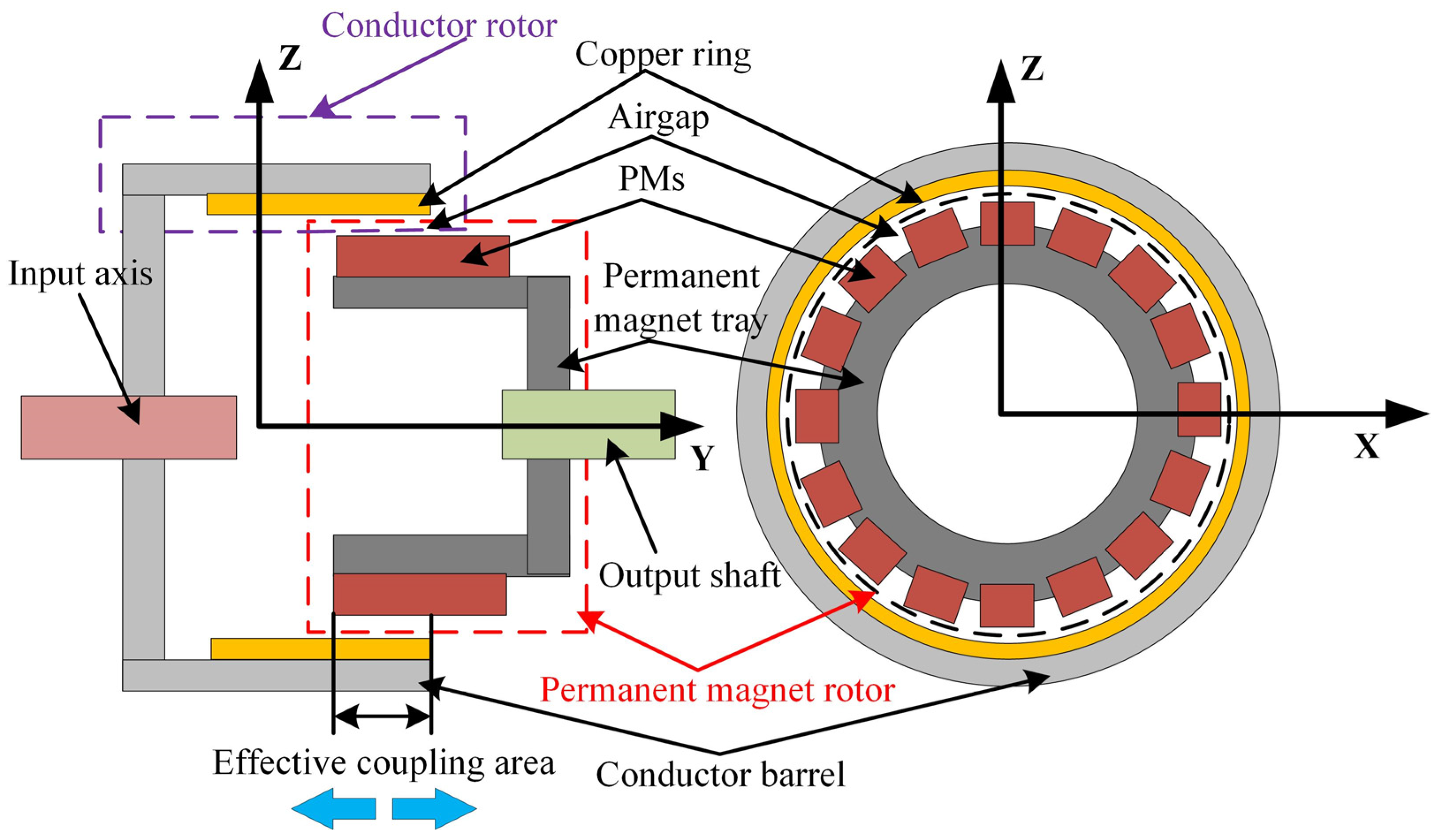
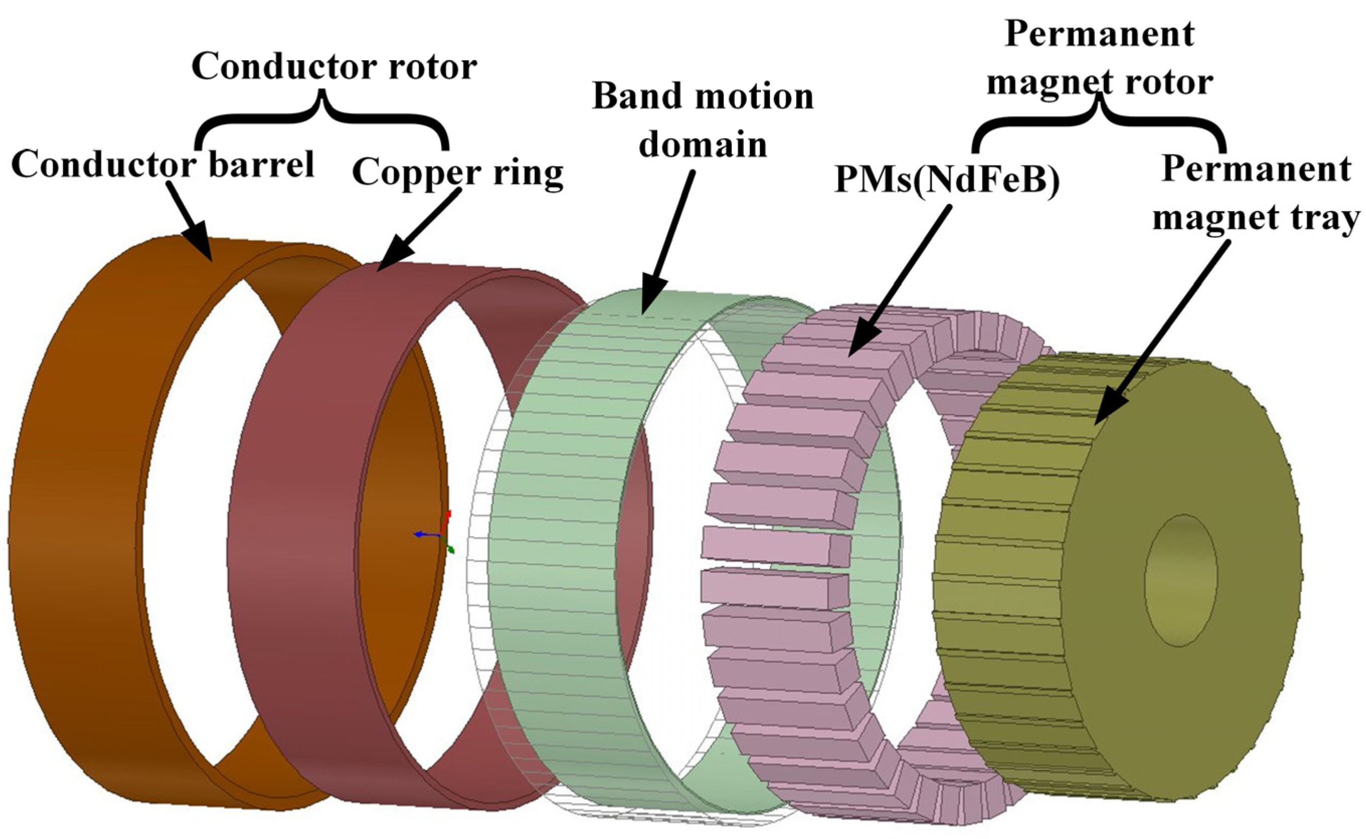
CPMG is composed of the conductor rotor, which is mainly composed of a conductor barrel, a copper ring and the permanent magnet rotor. The permanent magnet rotor contains a permanent magnet tray and PMs, where the PMs are embedded in the permanent magnet tray. As shown in Figure 1, the conductor rotor is connected to the motor shaft, and the output axis is connected to the permanent magnet rotor. There is no contact between the conductor and the permanent magnet rotor, which allows a certain alignment error during installation.
When the motor is in operation, the conductor barrel connected to the motor shaft is rotating, which cuts the magnetic field generated by the permanent magnet array. An induced current is generated in the copper ring. A Lorentz force is applied to the copper ring, which generates a torque to drive the permanent magnet array. There is always a rotation speed difference between the conductor and permanent magnet array in order to ensure the presence of output torque. The rotation speed of the output shaft and output torque can be adjusted by regulation of the effective coupling area between the conductor and the permanent magnet array.
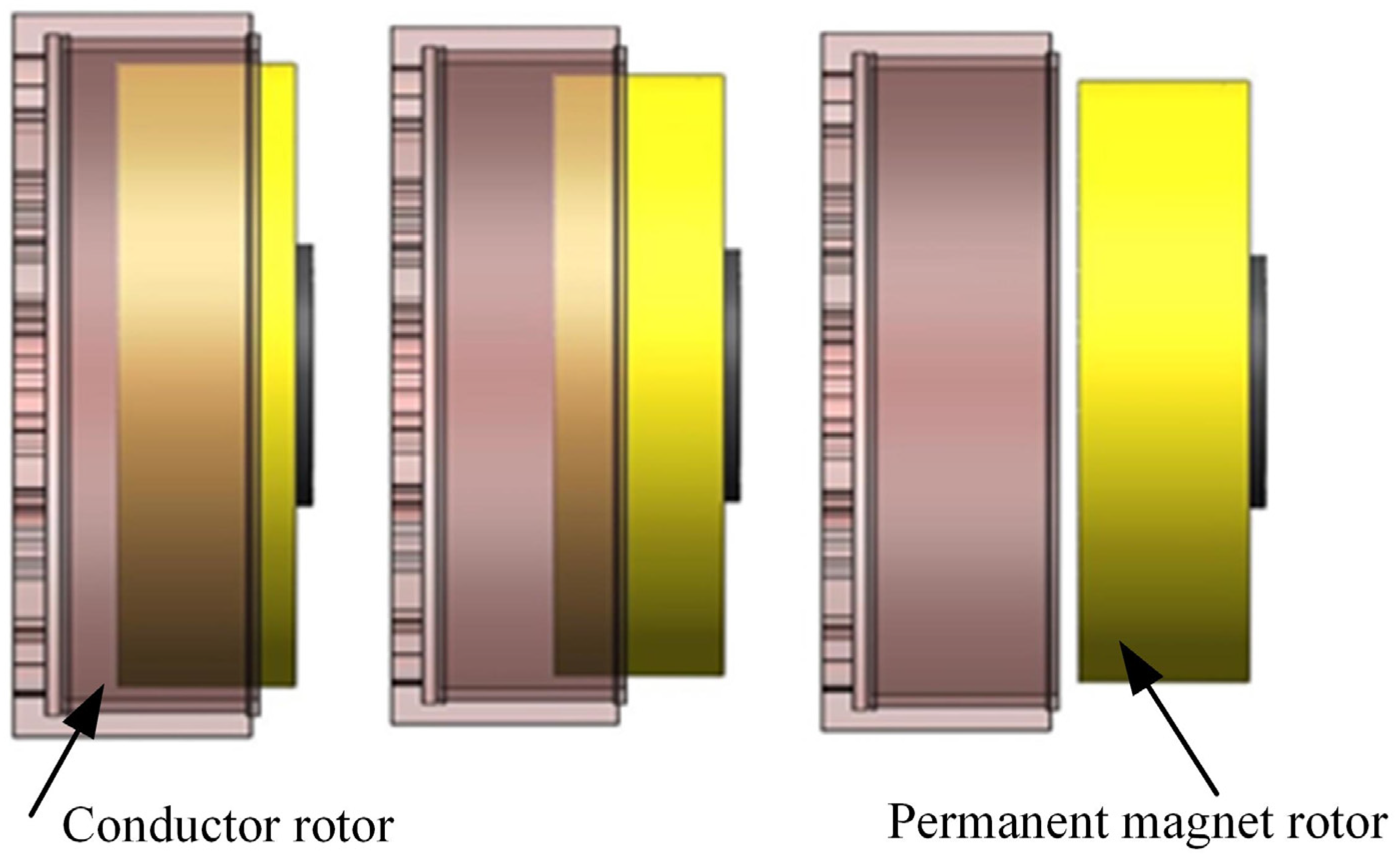
The schematic diagram of the specific speed regulation principle is shown in Figure 2. The output torque and rotation speed can be tuned through the adjustment of the effective coupling ratio (the ratio of the actual coincidence area between the conductor and the permanent magnet to the full coincidence area). The maximum output torque can be realized when the permanent rotor is fully coupled to the rotor of conductors (100% effective coupling ratio).
2.2. Equivalent Magnetic Circuit of Halbach Permanent Magnet Cell and Simulation Model
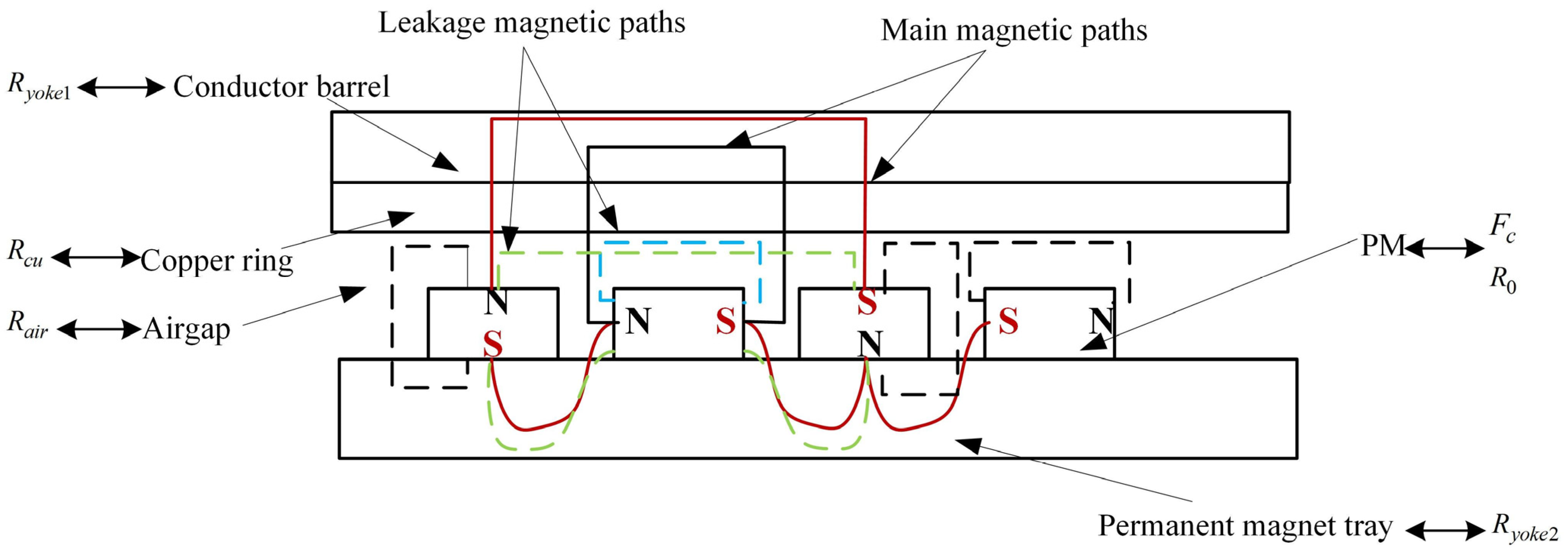
In order to simplify the process for analysis, the main components of CPMG were unfolded radially into a 2D model. The magnetic field distribution was assumed to be linear in CPMG without consideration of leakage. The equivalent model of a Halbach cell is shown in Figure 3. The permanent magnet’s geometry was considered to be rectangular shaped, which can be equalized to the magnetomotive. The main flux paths (solid line) were where it passes through PMs, airgap, copper ring, conductor barrel and permanent magnet tray. The leakage flux paths (dashed line) were mainly generated between adjacent permanent magnets.
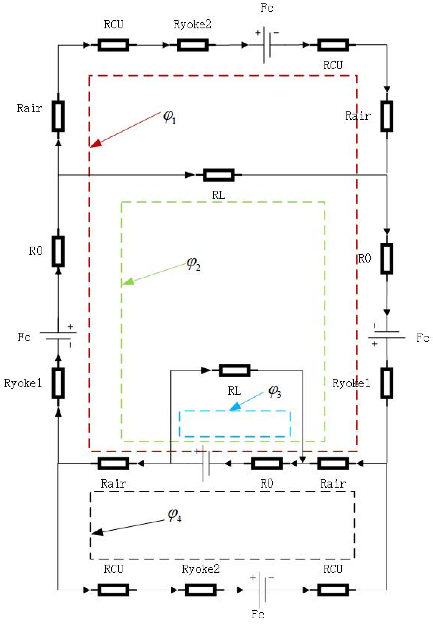
On the basic, before-mentioned Equivalent magnetic model of a Halbach permanent magnet cell analysis, the permanent magnet’s geometry is considered to be rectangular shaped, which is equalized to be magnetomotive. The Conductor barrel is regarded as , the permanent magnet tray is regarded as , the copper ring is regarded as , and the space in between the adjacent permanent magnets is regarded as . Therefore, the magnetic reluctance circuit of the Halbach permanent magnet cell is presented in Figure 4, where only a pair of Halbach array magnets is considered on account of the symmetry of the magnetic circuit.
According to the principles of equal magnetic circuits, a magnetic circuit was studied under a pair of magnetic poles, and a permanent magnet was regarded as the magnetomotive force , in series with the internal reluctance of the permanent magnet, to form the magnetomotive force source.
where Hc is the coercive force of the permanent magnet, and hmp is the magnetization direction length of the permanent magnet. When the permanent magnet governor is operating, the induced electromotive force in the copper ring during the cutting of the magnetic field generated by the permanent magnet array is created by the eddy current, which increases the armature magnetomotive force Fa.
The magnetic reluctance in the circuit is calculated below:
where L represents the length and S represents the cross-section of the magnet circuit, and represents the magnetic permeability.
According to the current KCL law, the magnetic circuit equations of the Halbach magnet cell are built as below:
In Equation (3), , , and represent the flux of air between the four magnets.
Magnetic induction strength in the air gap
where is the average magnetic flux of the pair of polar poles and is a cross-sectional area that corresponds with the air gap.
The average electromotive force is calculated as follows:
The induced current inhibits the penetration of magnetic fields in the ring of copper, and it only allows magnetic fields to penetrate at a specific depth, which is called the skin effect. Due to the skin effect, the inducing currents are concentrated at the surface of the copper ring. The current decays rapidly beyond the depth of penetration. The penetration is decreased with the rotation frequency. The penetration depth expression is as follows
In Equation (6), is a radial frequency, is copper conductivity, and represents the relative permeability of copper rings. In Equation (7), is the speed difference and is the number of pole pairs.
The induced eddy current region is generated by a single permanent magnet on the copper ring, which is equivalent to a circular region with a diameter of d. Therefore, the reluctance of the ring of the eddy current is shown below:
The area of the eddy current region is as follows:
The instantaneous eddy current obtained from the above equation is:
The eddy current loss generated by the permanent magnet corresponding to the copper ring is
where n is the number of permanent magnet blocks.
Since the permanent magnet governor is connected to a constant torque load, according to the energy conservation law, which can be obtained:
Simulation Model
The simulation model of the CPMG is built by using Maxwell Software, as shown in Figure 5. It is mainly composed of a conductor rotor and a permanent magnet rotor, and a band motion domain. The conductor rotor contains a conductor barrel and a copper ring, where the copper ring is welded to the inner wall of the conductor barrel. The permanent magnet rotor contains a permanent magnet tray and PMs (NdFeB), where the permanent magnets are embedded in the permanent magnet array tray by means of a Halbach array. The number of PMs is 36. In addition, The band motion domain is a finite element mesh restriction and not an actual structure.
The material of the CPMG parts is given, of which the material of the conductor rotor and the permanent magnet rotor is Steel_1008, and the permanent magnet is selected N48H.
Due to the components of the copper ring, the induced currents in the copper ring are crucial for the transfer of the output torque to the CPMG. Therefore, it is particularly important to pay attention to the meshing subdivision of permanent magnets and the copper ring in the 3D FEM, as shown in Figure 6. In order for the higher precision results to be obtained, the quality of meshing of CPMG should be above 0.3. Moreover, it should be noted that 3D FEM results with stabilization and convergence are taken as valid data, the residual error of which is less than the set value ().
3. Analysis of Results
3.1. Magnetic Field Distribution
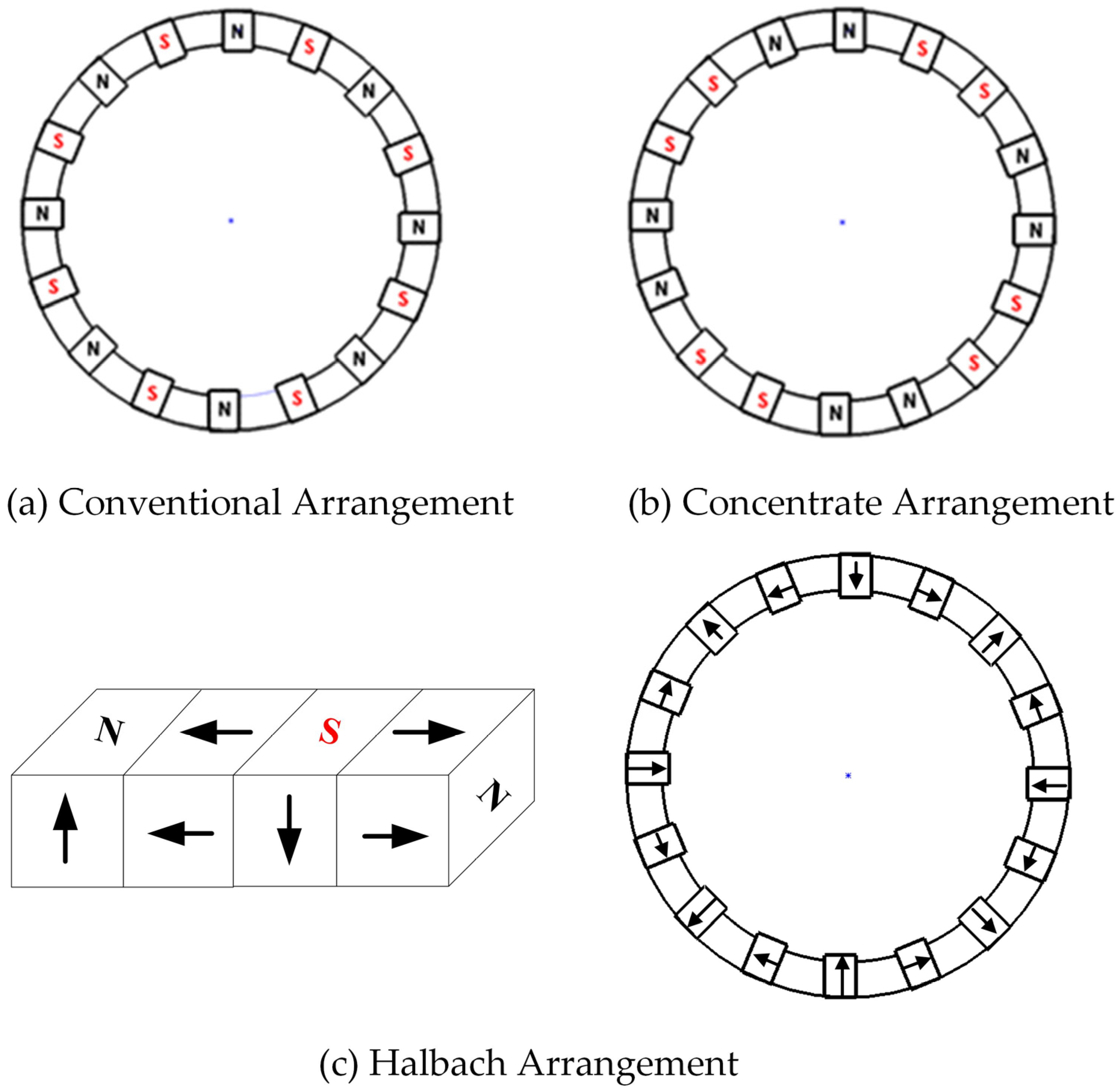
The output torque of CPMG is determined by the magnet field in the air gap between the conductor and the permanent magnet. As shown in Figure 7, there are three types of permanent magnet arrangements in Figure 7.
The air gap flux in the above three arrangements is compared and analyzed. The distribution of magnetic field lines is studied under static magnetic field conditions, and the boundary condition is 0 vector boundary. In Figure 8, the magnetic flux density distributions are shown, and the magnetic field is more dense in the Halbach arrangement CPMG than in the conventional and concentrated arrangement. However, a small part of the magnetic field lines directly returns to the adjacent S pole through the air gap, which causes a few flux leakage. Most of the magnetic flux lines are concentrated in the air gap and the conductor side, which realizes the effect of unilateral magnetic concentration.
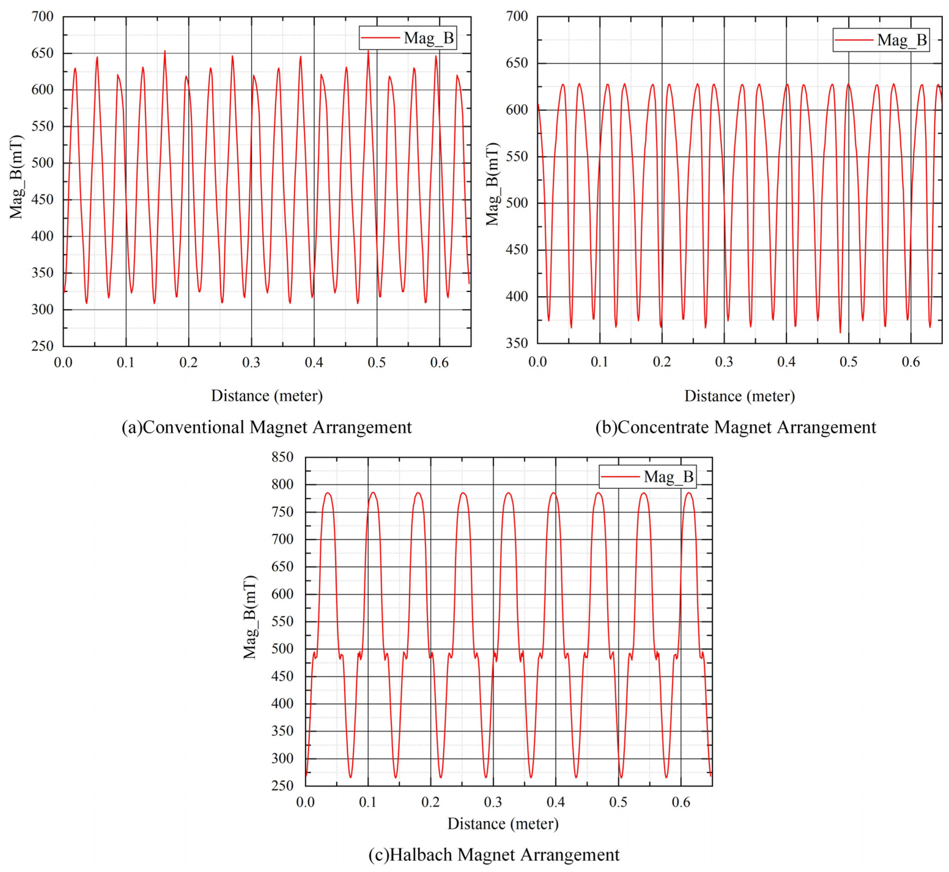
The magnetic flux density of CPMG under the different PMs arrangements was quantitively compared. According to Figure 9, the density of magnetic flux density in the air gap is different under different magnet arrangements. It is clear that the flux density in the airgap of the Halbach arrangement is more than that of the conventional arrangement and concentrate arrangement under the same number of magnets. Because of the symmetries of a permanent magnet, the magnetic flux density curve shows the sine-variations under the Halbach arrangement, which can improve transmission stability. The magnetic characteristics in the air gap with different arrangements are listed in Table 1. The average magnet density in air gaps with the Halbach arrangement is 13% and 6.2% higher than the other two arrangements, respectively.
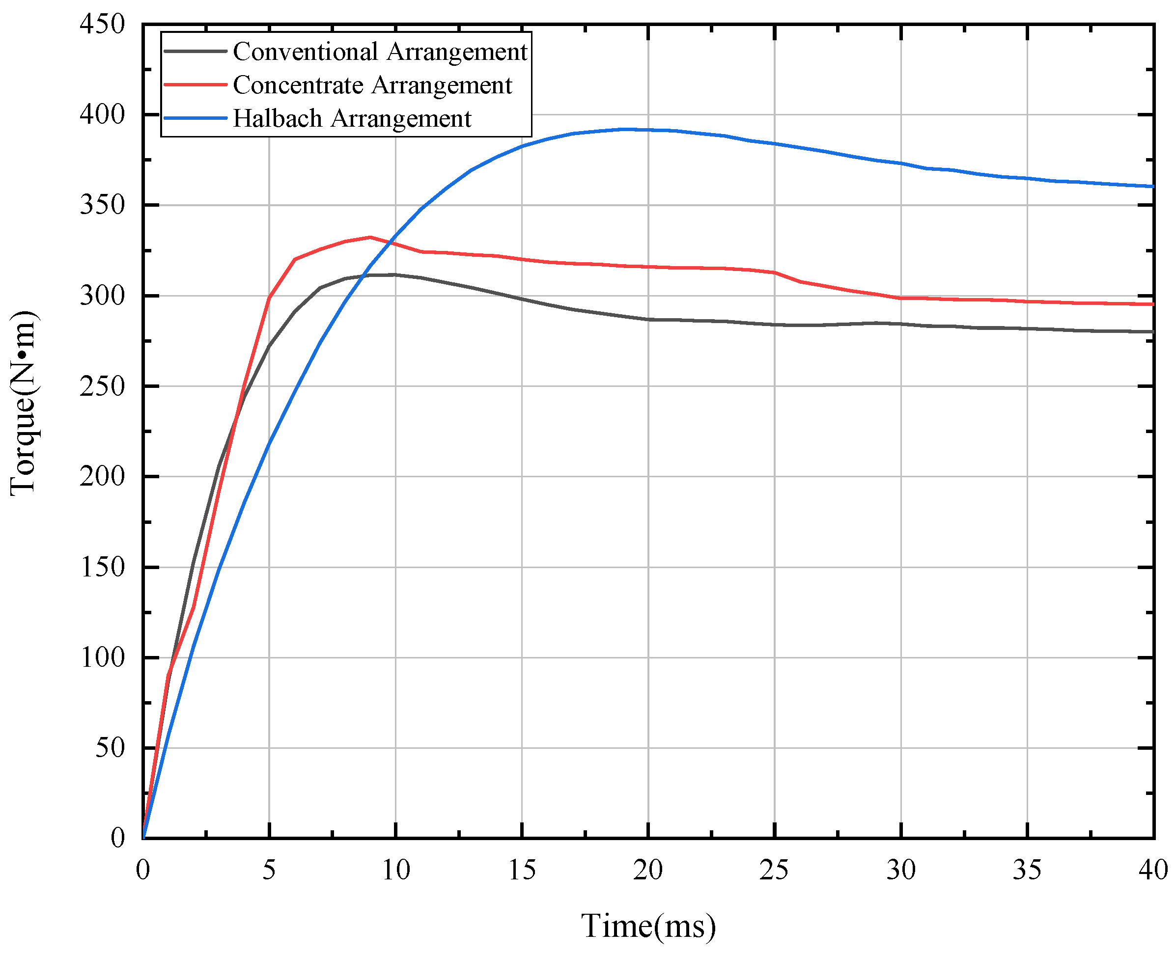
At the beginning of the simulation, the input rotation speed was maintained at 1000 rpm, and the output rotation speed was maintained at 900 rpm. The transient output torque of CPMG under different magnets arrangements are shown in Figure 10. It is clear that the Halbach arrangement has the highest output torque. The detailed comparison is listed in Table 1. As shown in Table 1, The average output torque of the Halbach arrangement is increased by 15.89% and 10.31%, which is compared to the conventional arrangement and concentrate arrangement.
3.2. Eddy Current Density Distribution in the Copper Rings
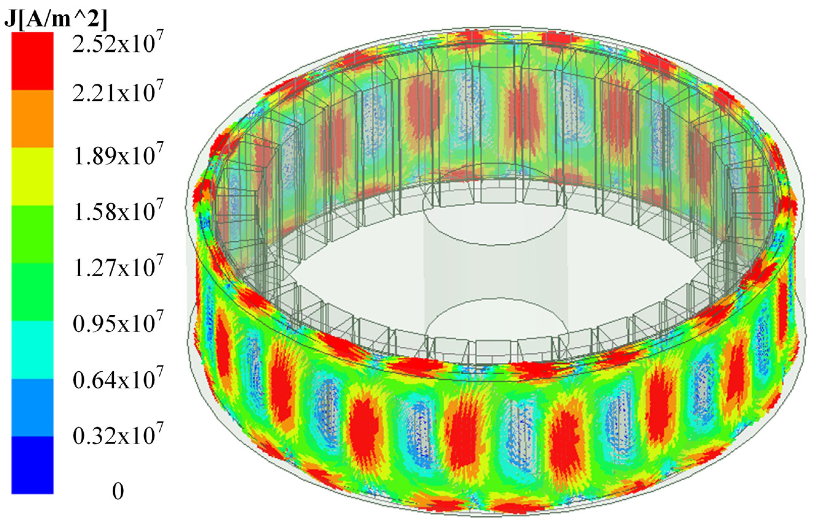
When the slip rate is 0.01, and the effective coupling ratio between the conductor and permanent magnet is 100%, the distribution of the eddy current density in the copper ring is illustrated in Figure 11. As we can see in Figure 11, the eddy current density of the permanent magnet in the copper ring is the largest area mapped to the area of the copper ring. At a maximum density of 2.52 × 10⁷ Am−2, the eddy current density between adjacent permanent magnet mapping areas dropped sharply and reduced to 3.20 × 10⁶ Am−2. The center of the loop formed by the induced eddy current in the copper ring is located in the center between the two mapping regions of permanent magnets. The induced magnetic field generated by the circular eddy current interacts with the permanent magnetic field, thereby providing torque for CPMG.
3.3. Ohmic Loss in the Copper Ring
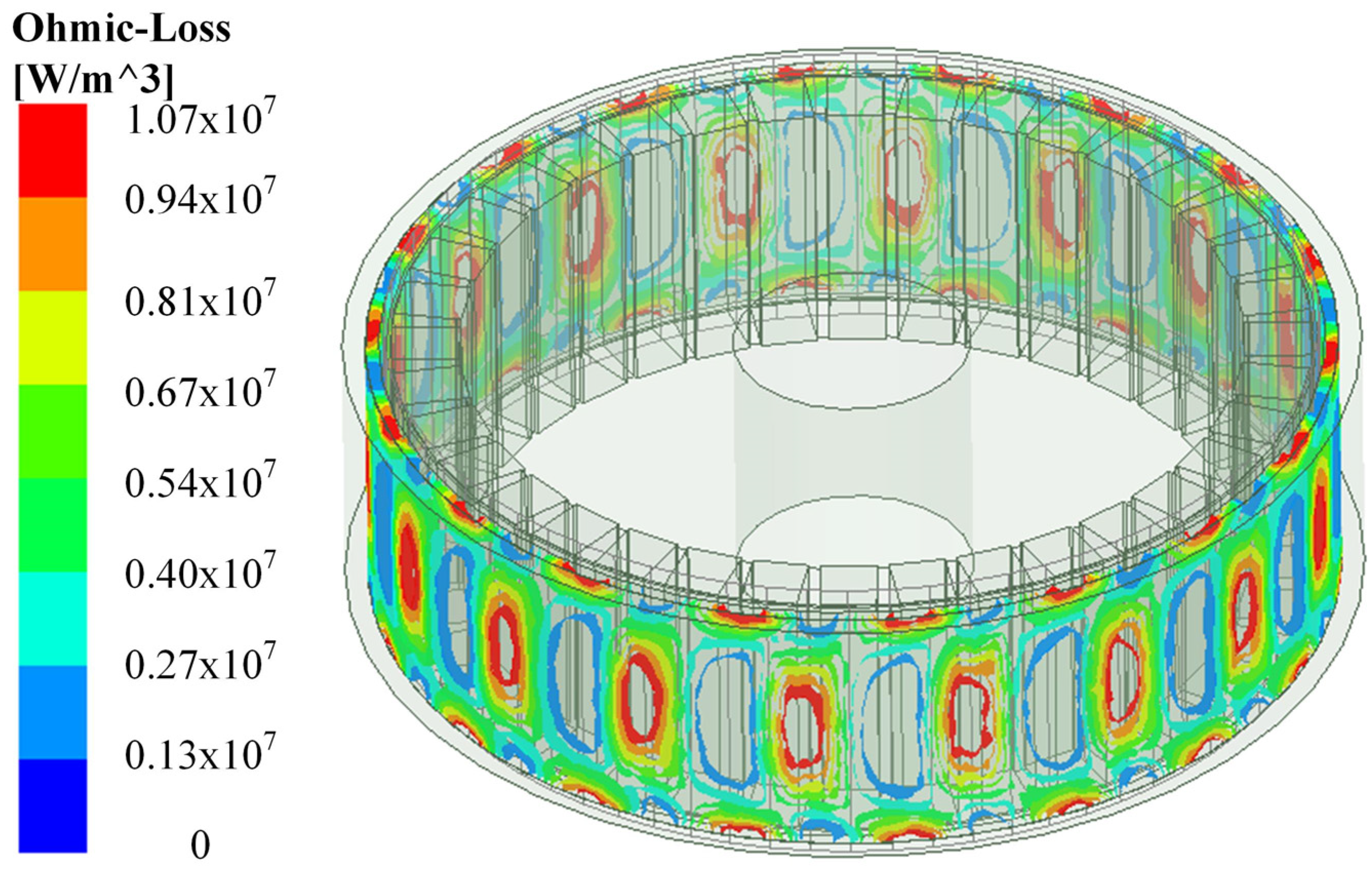
The induced current generated in the copper coil of the permanent magnet regulator produces Ohmic loss due to the existence of the coil reluctance. The Ohmic loss distribution of the copper ring under 0.1 slip rate and 100% effective coupling ratio is shown in Figure 12. The maximum Ohmic loss is concentrated in the center of the copper ring. Moreover, the Ohmic loss is increased with the effective coupling ratio between the conductor and permanent magnet.
3.4. Output Torque of CPMG
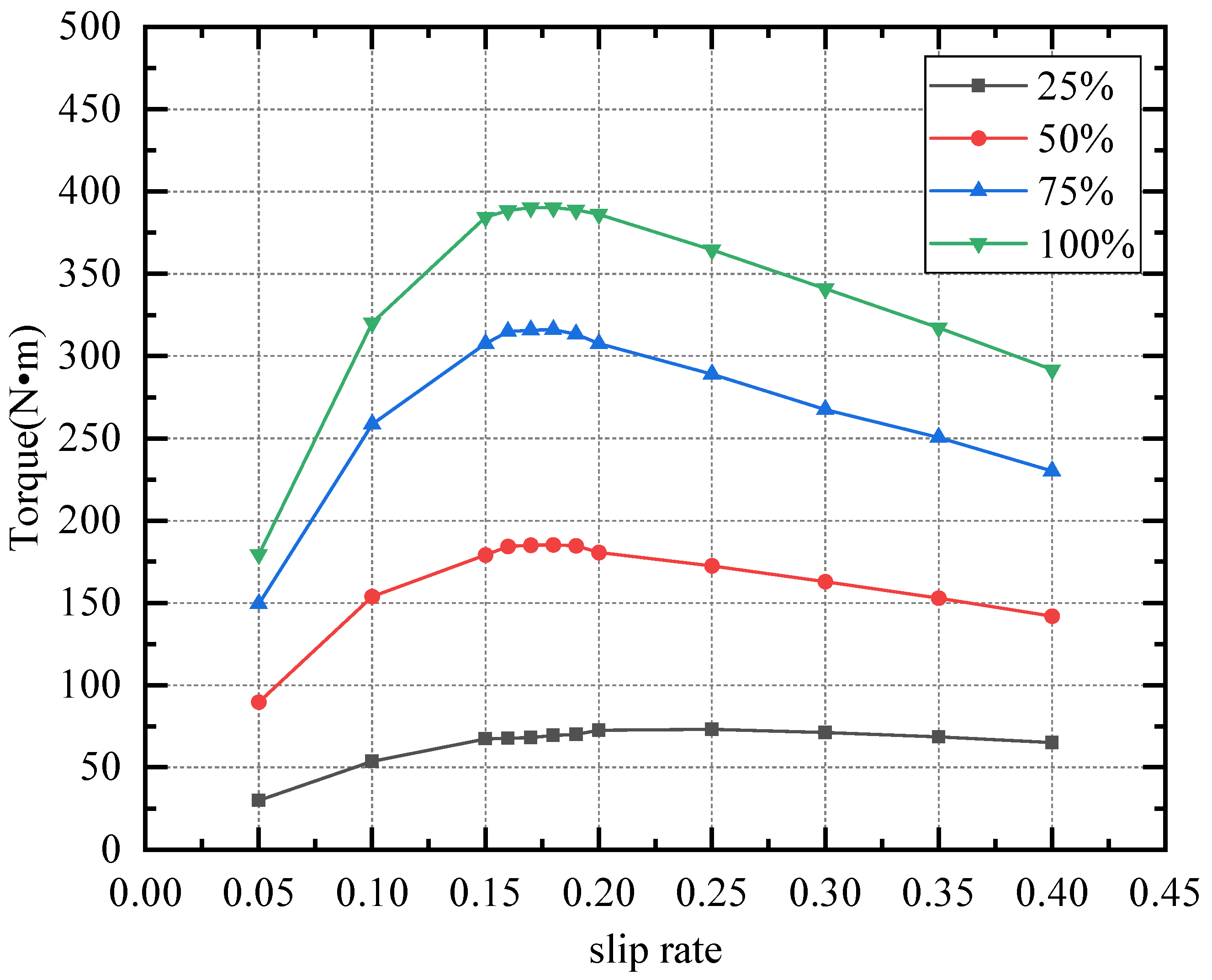
During the simulation, the input rotation speed is maintained at 1000 rpm, and the output rotation speed is adjusted from 600 to 950 rpm, which means the slip rate range from 0.05 to 0.4. The thickness of the copper ring is 6 mm. The output torque of CPMG under the different slip rates and effective coupling ratio is listed in Table 2 and shown in Figure 13. The output torque is increased with the effective coupling ratio at a constant slip rate. The output torque is increased first, then decrease the slip with a constant effective coupling ratio, whose peak value is 74.56 N·m at 230 rpm output rotation speed (slip rate = 0.23) with a 25% effective coupling rate. The peak output torque is 185.20 N·m, 316.01 N·m and 390.28 N·m at 180 rpm (slip rate = 0.18) with 50%, 75% and 100% effective coupling rates, respectively.
3.5. Influence of Copper Ring Thickness on Transmission Performance
In the transmission process of the CPMG, the main function of the copper ring is to be cut to magnetic wire induced by the permanent magnets, generating eddy currents. However, the changes in the thickness of the copper ring cause a change in resistance to copper; thus, the thickness of the copper ring has an important effect on transmission performance.
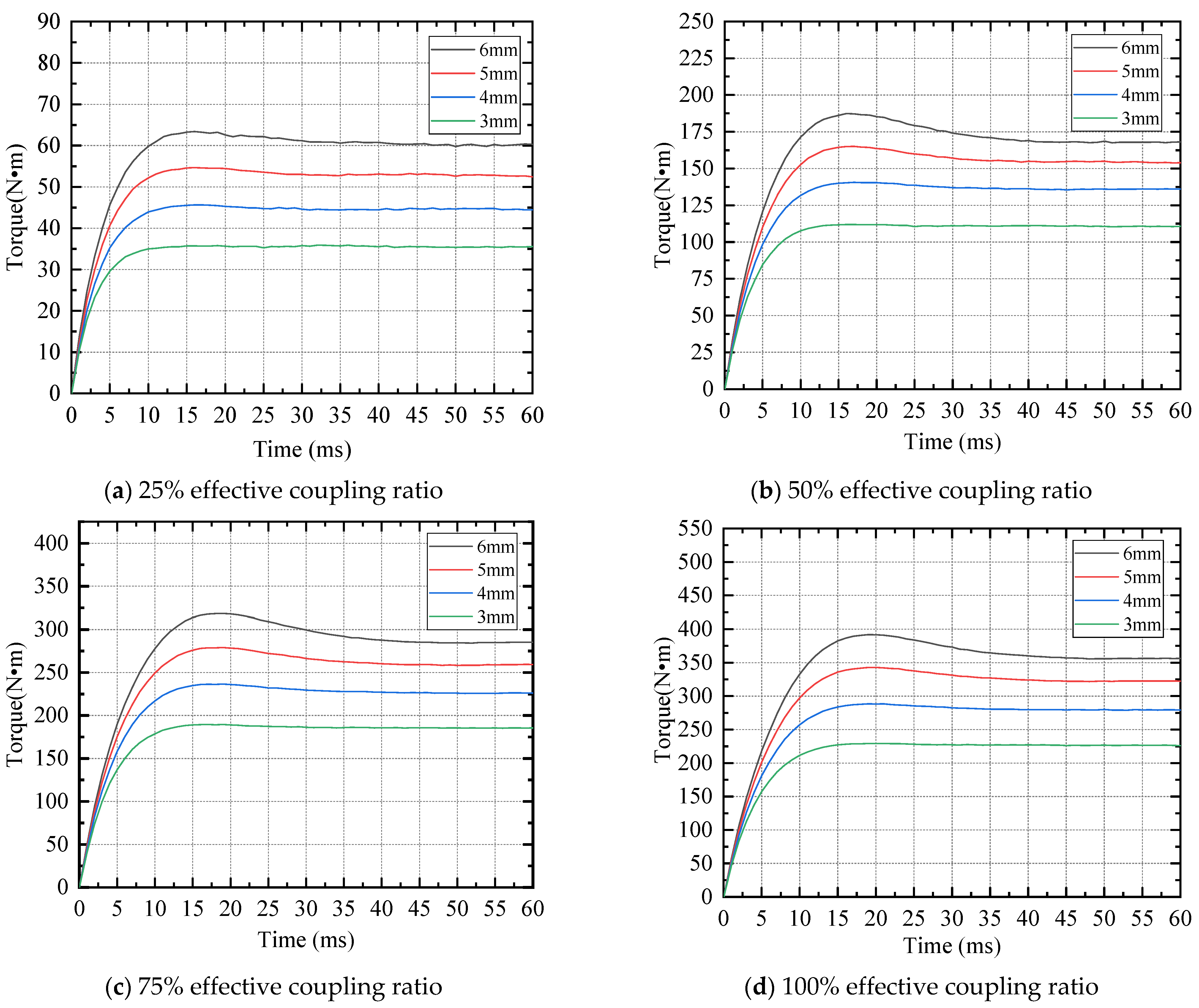
At the beginning of the simulation, the input rotation speed was maintained at 1000 rpm, and the output rotation speed was maintained at 900 rpm. The transient output torque of CPMG 25%, 50%, 75% and 100% effective coupling ratio under difference copper ring thickness is shown in Figure 14.
As shown in Figure 14, the transient output torque of CPMG has an overshoot at the beginning due to a small damping ratio of the system. The output torque reached a stable value after dozens of ms. The transient output torque of CPMG with different copper ring thicknesses is shown in Figure 13. The transient output torque increases with the copper ring thickness.
The stable output torque for a different copper ring thickness under a constant effective coupling ratio and slip rate is listed in Table 3. The table shows the output torque peak value at 6 mm thickness and 100% effective coupling ratio, which is 340.05 N·m. The output torque increases with the copper ring thickness. However, the minimum value of the air gap must be greater than 5 mm taking into account the assembly problems and costs in the actual production process, which is limited to the copper ring thickness. Here, we take the maximum copper ring thickness as 6 mm.
4. Experimental Analysis
4.1. Setup of Experimental Platform
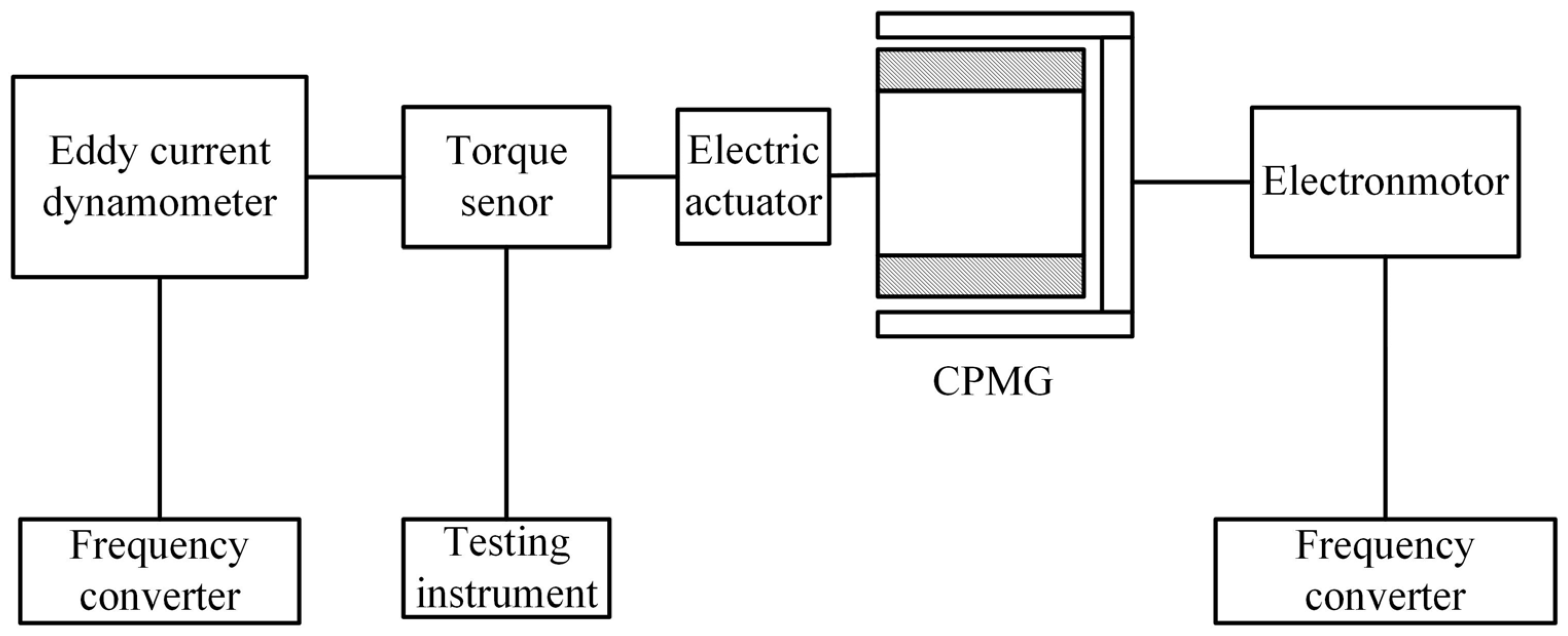
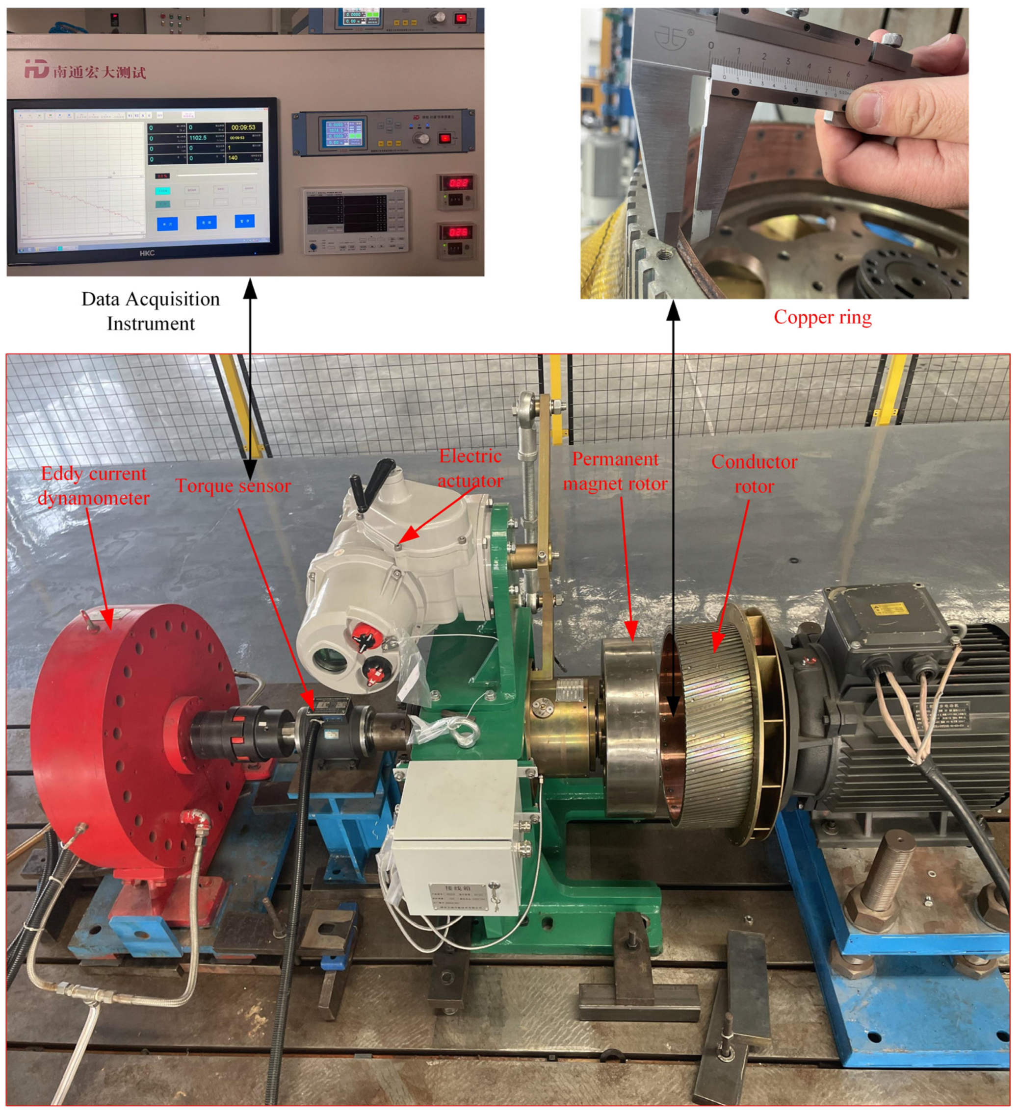
To verify the correctness of the transmission characteristic model and the accuracy of the calculation results. An experimental platform was constructed, as shown in Figure 15, including an eddy current dynamometer providing the required output load, which can change the load by adjusting its control current. A torque sensor measures the output torque; the CPMG can be tested; and the YE2-200L-4 three-phase asynchronous motor is an electromotor providing the driving torque, where the rated output power of the motor is 30 kW, the rated rotation speed is 1470 rpm, and the rated current is 56.8 A. Two frequency converters control the rotating speed of the electromotor and eddy current dynamometer, and the testing instrument displays the output torque. An IKTM1000 electric actuator is connected to the rotor of the conductor to realize the adjustment of the effective coupling ratio. All these components were installed on the test platform, as shown in Figure 16.
The thickness of the copper ring is measured in advance of the test, and the copper ring is assembled in the inner wall of the conductor barrel. The Gaussian meter was used to measure the air gap magnetic field after assembly. Finally, the CPMG was started, and the torque data were sampled by the test equipment.
4.2. Output Torque Test
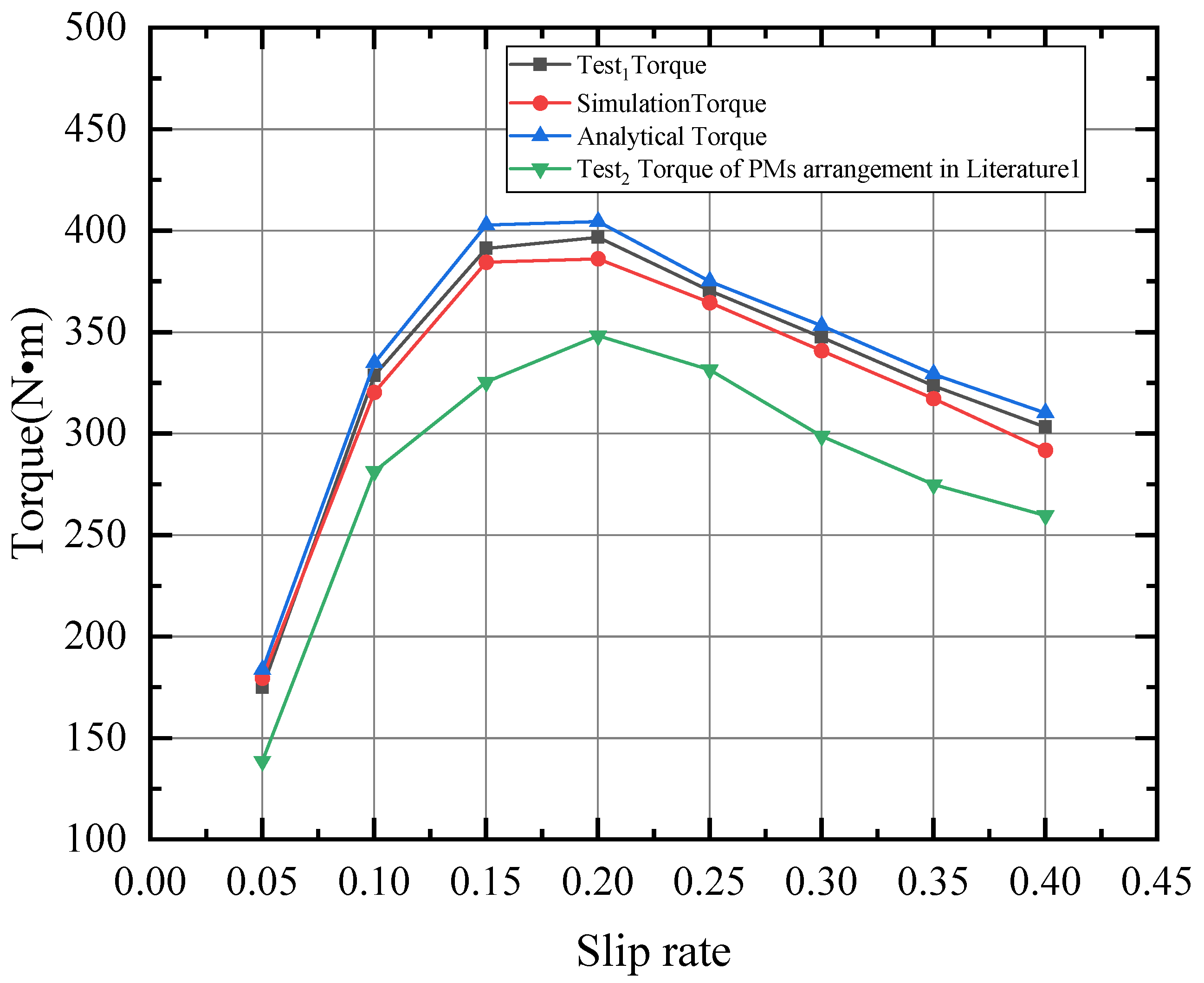
The CPMG 100% effective coupling ratio, 6 mm thickness of the copper ring for testing, and start motor were selected. The CPMG input speed (speed of the conductor motor) was maintained at 1000 rpm; the output torque of the Permanent Magnet Rotor was tested at 950 rpm, 900 rpm, 850 rpm, 800 rpm,750 rpm, 700 rpm, 650 rpm, 600 rpm (slip rate range from 0.05 to 0.4), respectively; and the average air gap flux measured by the Gauss meter was substituted into the torque equation derived in Section 2.2 through MATlab software to be calculated, which is the analytical torque. The output torque test was carried out on the experimental platform. The experimental data, which are , were obtained with the slip rate range from 0.05 to 0.4 and compared with the theoretical calculation data and simulation results, as shown in Figure 17. The experimental results show that the variation trend of the output torque is consistent with numerical simulation. The maximum output torque is reached when the slip rate is 0.2. The error of experimental results of output torque compared with analytical and numerical counterparts are less than 5%, under 100% effective coupling ratio and 6 mm copper ring thickness. The output torque of CPMG does not always increase with the increased slip rate. This is due to the adverse effects of the inductive magnetic field of permanent magnets. In addition, the slip rate increases the skin effect, which reduces the equivalent permeability in the copper ring, thereby reducing the intensity of the induced current in the copper ring, leading to the transfer of torque that is gradually reduced.
According to the magnet arrangement in Ref. [1], the same size and quantity of PMs were installed in the CPMG for testing. Additionally, the CPMG was operated, and the torque data were sampled by the test equipment. The detailed comparison is listed in Table 4. During the test, the output torque of the Halbach array was higher than the magnets’ arrangement in Ref. [1]. Furthermore, the peak torque of the Halbach array was increased by 12.21% when compared to the magnet arrangement in Ref. [1].
In Table 4, represents the test measurements of the Halbach array, is simulated stable torque, represents the test measurements of PMs arrangement in Ref. [1]. is the theoretical torque of the theoretical analysis of the principle of the equivalent magnetic circuit. is the error between the simulation and the experimentation. is the error between the theoretical analysis and the experimentation.
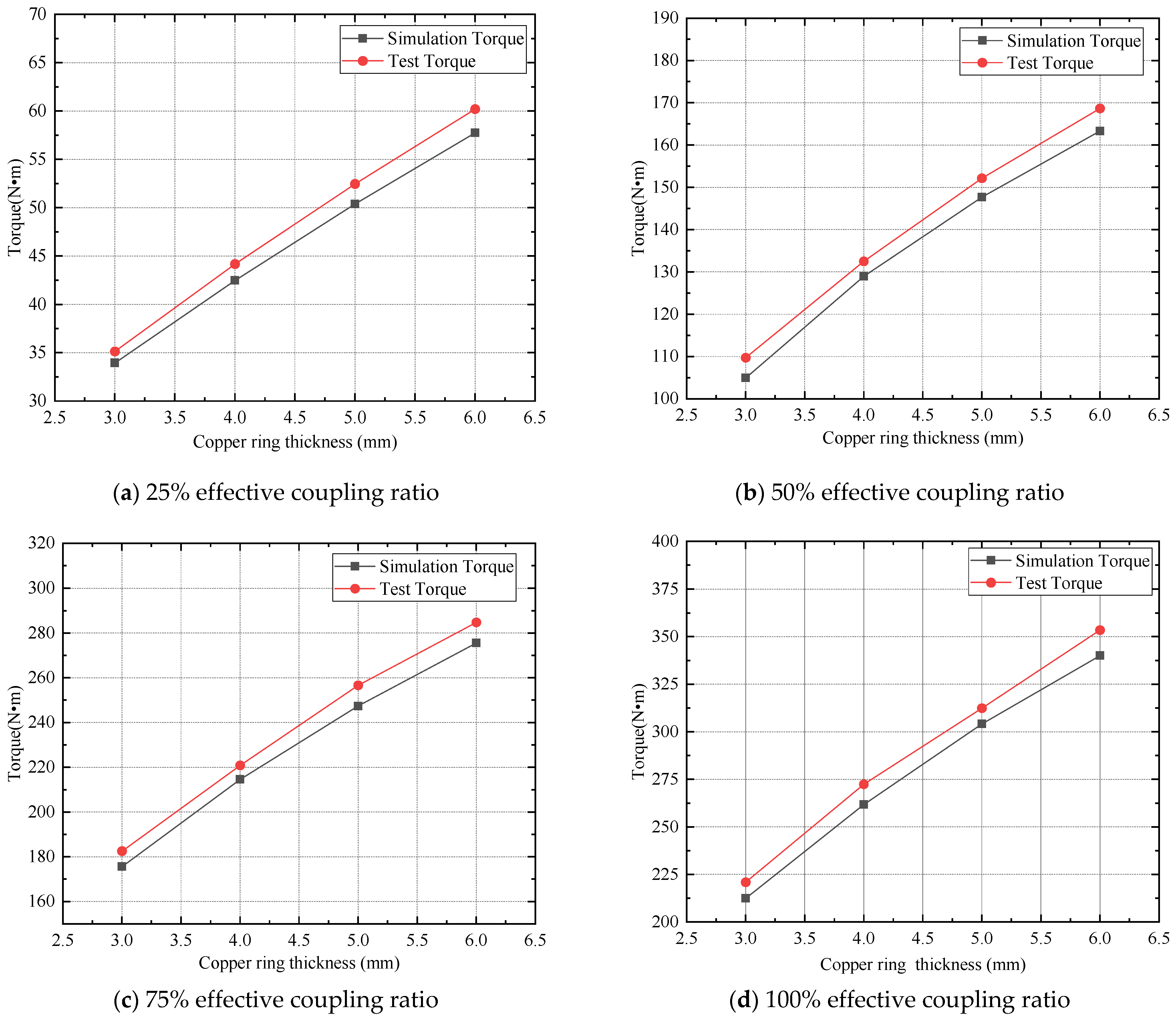
In order to test the effect of the thickness of the copper ring on the output torque of the CPMG, a series of copper ring thicknesses of 6, 5, 4 and 3 mm, respectively, were installed in the inner walls of the conductor barrel and the tested output torque in the different effects of the coupling. During the test procedure, the speed of the input CPMG was maintained at 1000 rpm, and then the speed of the permanent magnet rotor was adjusted at 900 rpm (the slip rate was 0.1) to test the output torque of the CPMG. The test results were obtained and compared with the numerical simulation results, as shown in Figure 18. The torque measured by the sensor and obtained by a finite element is shown below in Table 5. When the effectiveness of the coupling is constant, the torque of the output increases with the increasing thickness of the ring of copper. The errors of experimental results of output torque compared with the numerical counterpart are less than 5%.
5. Conclusions
This paper shows a comparative analysis of the performance of the CPMG under the three different types of PM arrangements. Considering the same number of PMs and the cost, the Halbach array is suitable for high-torque appliances, such as high-power fans. The main magnetic fluxes are considered to obtain a comprehensive equivalent magnetic circuit model of the CPMG with Halbach array, and analytical output torque is calculated. Moreover, the transmission properties of the CPMG under the Halbach array were studied, taking into account the effects of slip rate, effective coupling ratio and thickness of the copper ring on the torque output of the CPMG under the Halbach array. By comparing the simulation results with the field-test data of the CPMG, it was found that the simulation results match well with the measured data, which validates the effectiveness of the proposed model and calculation method. The main conclusion of this paper is summarized as follows:
- The air gap flux density under the Halbach arrangement is 13% and 6.2% higher than the other two arrangements, respectively. The average output torque of the Halbach arrangement is increased by 15.89% and 10.31%, which is compared with the conventional arrangement and concentrate arrangement.
- When the effective coupling ratio and the thickness of the copper ring are constant, the output torque increases first and then drops with the slip rate increasing, which reaches the maximum torque of around 0.2. The results were consistent with the results of the simulation, and the error was kept within the range of 5%. The output torque of the Halbach array is higher than the magnets’ arrangement in Ref [1]. The peak torque of the Halbach array is 12.21% higher when compared to the magnets’ arrangement in Ref. [1].
- When the slip rate is constant, the output torque increases with the increase in the effective coupling ratio (between conductor and magnet), and the thickness of the copper ring increases.
Author Contributions
Conceptualization, H.W. and C.Y.; methodology, H.W., Y.Z. and C.Y.; software, J.G.; validation, C.Y.; formal analysis, C.Y. and Y.Z.; investigation, H.W.; resources, C.Y.; data curation, H.W. and H.L.; writing—original draft preparation, H.W.; writing—review and editing, Y.Z.; visualization, H.W. and C.Y.; supervision, C.Y.; project administration, H.W. and C.Y.; funding acquisition, J.G. All authors have read and agreed to the published version of the manuscript.
Funding
This research was funded by “The overseas study visit and training program for outstanding young backbone talents of Anhui Province, grant number gxgwfx2021035”, “Graduate Student Innovation Project of Anhui Province, grant number 2022xscx097 ”, “The Innovation team of Anhui Polytechnic University, Special display and Imaging Technology Anhui Technology Innovation Center open project, grant number 2020AJ06001 ” and “Anhui Polytechnic University-Jiujiang District Industrial Collaborative Innovation Special Fund Project, grant number 2022cyxtb4”.
Conflicts of Interest
The authors declare no conflict of interest.
Sample Availability
Samples of the compounds are available from the authors.
Abbreviations
The following abbreviations are used in this manuscript:
| DPMG | disk permanent magnet governor; |
| CPMG | cylindrical permanent magnet governor; |
| MEC | magnetic equivalent circuit; |
| MCT | marine current turbine; |
| PM | permanent magnet; |
| PMR | permanent magnet rotor; |
| KCL | Kirchhoff current law. |
References
- Cheng, X.; Liu, W.; Zhang, Y.; Liu, S.; Luo, W. A Concise Transmitted Torque Calculation Method for Pre-design of Axial Permanent Magnetic Coupler. IEEE Trans. Energy Convers. 2020, 35, 938–947. [Google Scholar]
- Seo, S.W.; Kim, Y.H.; Lee, J.H.; Choi, J.Y. Analytical torque calculation and experimental verification of synchronous permanent magnet couplings with Halbach arrays. AIP Adv. 2020, 8, 056609. [Google Scholar] [CrossRef]
- Wang, L.; Jia, Z.Y.; Zhang, L. Investigation on the accurate calculation of the temperature field of permanent magnet governor and the optimization method of heat conduction. Case Stud. Therm. Eng. 2019, 13, 100360. [Google Scholar] [CrossRef]
- Guo, B.; Li, D.; Shi, J.; Gao, Z. A Performance Prediction Model for Permanent Magnet Eddy-Current Couplings Based on the Air-Gap Magnetic Field Distribution. IEEE Trans. Magn. 2022, 58, 1–9. [Google Scholar] [CrossRef]
- Dolisy, B.; Mezani, S.; Lubin, T.; Levrque, J. A new analytical torque formula for axial field permanent magnets coupling. IEEE Trans. Energy Convers. 2015, 30, 892–899. [Google Scholar] [CrossRef] [Green Version]
- Yang, X.; Liu, Y.; Wang, L. An Improved Analytical Model of Permanent Magnet Eddy Current Magnetic Coupler Based on Electromagnetic-Thermal Coupling. IEEE Access 2020, 8, 95235–95250. [Google Scholar] [CrossRef]
- Shi, J.; Suo, S.; Meng, G. The theoretical calculation model of torque transmission in permanent-magnet couplers. AIP Adv. 2021, 11, 025303. [Google Scholar] [CrossRef]
- Orlova, S.; Konuhova, M.; Kamolins, E.; Otankis, R. Design of magnetic couplings for bioreactors: Analytical treatment and optimization. In Proceedings of the 2018 20th European Conference on Power Electronics and Applications (EPE’18 ECCE Europe), Riga, Latvia, 17–21 September 2018. [Google Scholar]
- Sun, K.; Shi, J.; Cui, W.; Meng, G. Theoretical Computational Model for Cylindrical Permanent Magnet Coupling. Electronics 2021, 10, 2026. [Google Scholar] [CrossRef]
- Deshan, K.; Dazhi, W.; Wenhui, L.; Sihan, W.; Zhong, H. Analysis of a novel flux adjustable axial flux permanent magnet eddy current coupler. IET Electr. Power Appl. 2023, 17, 181–194. [Google Scholar] [CrossRef]
- Park, J.; Paul, S.; Chang, J.; Hwang, T.; Yoon, J. Design and comparative survey of high torque coaxial permanent magnet coupling for tidal current generator. Electr. Power Energy Syst. 2020, 120, 105966. [Google Scholar] [CrossRef]
- Taqavi, O.; Taghavi, N. Development of a Mixed Solution of Maxwell’s Equations and Magnetic Equivalent Circuit for Double-Sided Axial-Flux Permanent Magnet Machines. IEEE Trans. Magn. 2021, 57, 1–11. [Google Scholar] [CrossRef]
- Yang, C.; Peng, Z.; Tai, J.; Zhu, L.; Telezing, B.J.K. Torque characteristics analysis of slotted-type eddy-current couplings using a new magnetic equivalent circuit model. IEEE Trans. Magn. 2020, 56, 1–8. [Google Scholar] [CrossRef]
- Lubin, T.; Mezani, S.; Rezzoug, A. Experiment and analytical analyses of axial magnetic coupling under steady-state and transient operations. IEEE Trans. Ind. Electron. 2014, 61, 4356–4365. [Google Scholar] [CrossRef] [Green Version]
- Kim, I.C.; Wata, J.; Tongphong, W.; Yoon, J.S.; Lee, Y.H. Magnetic Coupling for a 10 kW Tidal Current Turbine: Design and Small Scale Experiments. Energies 2020, 13, 5725. [Google Scholar] [CrossRef]
- Lukočius, R.; Vilkauskas, A.; Marčiulionis, P.; Grigaliūnas, V.; Nakutis, Ž.; Deltuva, R. An Analysis of Axial Magnetic Coupling Force and Torque Dependencies on Its Structure Parameters Using a 3D FEM. Appl. Sci. 2022, 12, 6546. [Google Scholar] [CrossRef]
- Tian, M.; Zhao, W.; Wang, X.; Wang, D.; Yang, Y.; Diao, J.; Ma, X. Analysis on a Novel Flux Adjustable Permanent Magnet Coupler With a Double-Layer Permanent Magnet Rotor. IEEE Trans. Magn. 2018, 54, 1–5. [Google Scholar] [CrossRef]
- Lu, X.; He, X.; Jin, P.; Huang, Q.; Yang, Y.; Diao, J.; Ma, X. General 3D Analytical Method for Eddy-Current Coupling with Halbach Magnet Arrays Based on Magnetic Scalar Potential and H-Functions. IEEE Trans Magn. 2021, 14, 8458. [Google Scholar] [CrossRef]
- Lee, H.J.; Joung, H.K.; Kim, C.H. Optimal Design of the Halbach Array of the Halbach Array of Magnetic Coupling. In Proceedings of the 2022 25th International Conference on Electrical Machines and Systems(ICEMS), Shanghai, China, 29 November–2 December 2022; pp. 1–5. [Google Scholar]
- Li, Y.; Hu, Y.; Guo, Y.; Song, B.; Mao, Z. Analytical Modeling and Design of Novel Conical Halbach Permanent Magnet Couplings for Underwater Propulsion. J. Mar. Sci. Eng. 2021, 9, 290. [Google Scholar] [CrossRef]
- Li, Z.; Zhang, L.; Qu, B.; Wang, D. Evaluation and analysis of novel flux-adjustable permanent magnet eddy current couplings with multiple rotors. IET Electr. Power Appl. 2021, 15, 754–768. [Google Scholar] [CrossRef]
- McGilton, B.; Crozier, R.; McDonald, A.; Mueller, M. Review of magnetic gear technologies and their applicants in marine energy. IET Reneaable Power Gener. 2018, 12, 174–181. [Google Scholar] [CrossRef]
- Mateev, V.; Marinova, I. Loss estimation of magnetic gears. Electr. Eng. 2020, 102, 387–399. [Google Scholar] [CrossRef]
- Zhao, X.; Niu, S. Design and optimization of a new magnetic-geared pole-changing hybrid excitation machine. IEEE Trans. Ind. Electron. 2017, 12, 9943–9952. [Google Scholar] [CrossRef]
- Huang, J.; Fu, W.; Niu, S.; Zhao, X. Comparative Analysis of Different Permanent Magnet Arrangements in a Novel Flux Modulated Electric Machine. IEEE Access 2021, 1, 14437–14445. [Google Scholar] [CrossRef]
- Yang, K.; Zhao, F.; Wang, Y. Analysis of Double Layer Permanent Magnet Flux Reversal Machines with Different Permanent Magnet Arrangements in Stator. IEEE Trans. Magn. 2021, 57, 1–5. [Google Scholar] [CrossRef]
- Li, B.; Yang, B.; Xiang, F.; Guo, J. Optimal Design of a New Rotating Magnetic Beacon Structure Based on Halbach Array. Appl. Sci. 2022, 12, 10506. [Google Scholar] [CrossRef]
Figure 1.
Structure of CPMG.

Figure 2.
Speed regulation principle of CPMG.

Figure 3.
Equivalent magnetic model of a Halbach permanent magnet cell.

Figure 4.
Magnetic reluctance circuit of Halbach permanent magnet cell.

Figure 5.
Simulation model of CPMG.

Figure 6.
Meshing of CPMG.

Figure 7.
Permanent magnet arrangement. (The direction of the arrow represents the direction of the magnetic poles).
Figure 7.
Permanent magnet arrangement. (The direction of the arrow represents the direction of the magnetic poles).

Figure 8.
Magnetic flux density distribution in CPMG.

Figure 9.
Magnetic flux density in the air gap along the tangential direction.

Figure 10.
Output torque of CPMG under different magnets arrangements.

Figure 11.
Eddy current distribution across copper rings.

Figure 12.
Ohmic loss distribution in the copper rings.

Figure 13.
Average output torque at different effective coupling ratio.

Figure 14.
Output torque of CPMG under different copper ring thicknesses.

Figure 15.
Basic structure diagram of test platform.

Figure 16.
Test prototype construction.

Figure 17.
Comparison of average output torque under different slip rates.

Figure 18.
Output torque simulation and test comparison under different thicknesses.


Table 1.
Comparison of the performance between different magnet arrangements.
| Type of Permanent Magnet Arrangement | Conventional Arrangement | Concentrate Arrangement | Halbach Arrangement |
|---|---|---|---|
| peak magnetic induction line (Wb/m) | 0.012 | 0.013 | 0.015 |
| average magnetic flux density (mT) | 497.98 | 511.30 | 545.15 |
| Peak magnetic flux density (mT) | 653.59 | 610.65 | 785.88 |
| Average output torque (N·m) | 269.40 | 287.26 | 320.30 |
Table 2.
Average output torque at different coupling ratio(N·m).
| Slip Rate | 25% | 50% | 75% | 100% |
|---|---|---|---|---|
| 0.05 | 30.10 | 89.83 | 149.51 | 179.49 |
| 0.1 | 53.75 | 153.95 | 258.58 | 320.30 |
| 0.15 | 67.42 | 179.15 | 307.52 | 384.38 |
| 0.16 | 67.84 | 184.23 | 314.96 | 388.46 |
| 0.17 | 68.12 | 185.04 | 315.95 | 390.26 |
| 0.18 | 69.48 | 185.20 | 316.01 | 390.28 |
| 0.19 | 70.12 | 184.74 | 313.28 | 388.82 |
| 0.2 | 72.64 | 180.70 | 307.63 | 386.12 |
| 0.25 | 73.13 | 172.62 | 289.09 | 364.51 |
| 0.3 | 71.31 | 162.94 | 267.45 | 340.86 |
| 0.35 | 68.54 | 152.96 | 250.59 | 317.23 |
| 0.4 | 65.08 | 141.98 | 230.19 | 291.81 |
Table 3.
Output torque at different copper ring thicknesses.
| Copper Ring Thickness (mm) | Effective Coupling Ratio (%) | |||
|---|---|---|---|---|
| 25 | 50 | 75 | 100 | |
| 6 | 57.75 | 163.33 | 275.57 | 340.05 |
| 5 | 50.40 | 147.72 | 247.39 | 304.18 |
| 4 | 42.49 | 128.97 | 214.60 | 261.73 |
| 3 | 33.95 | 104.95 | 175.63 | 212.46 |
Table 4.
Comparison of output torque under different speed differences.
| Slip Rate | ||||||
|---|---|---|---|---|---|---|
| 0.05 | 174.89 | 138.75 | 179.49 | 183.62 | 2.63% | 4.99% |
| 0.1 | 328.62 | 281.41 | 320.30 | 334.82 | 2.53% | 1.89% |
| 0.15 | 391.25 | 325.48 | 384.38 | 402.77 | 1.75% | 2.94% |
| 0.2 | 396.73 | 348.25 | 386.12 | 404.42 | 2.67% | 1.94% |
| 0.25 | 370.43 | 331.38 | 364.51 | 375 | 1.74% | 1.23% |
| 0.3 | 347.52 | 298.82 | 340.86 | 353.13 | 1.92% | 1.61% |
| 0.35 | 323.56 | 274.89 | 317.23 | 329.35 | 1.96% | 1.79% |
| 0.4 | 303.21 | 259.63 | 291.81 | 310.23 | 3.75% | 2.31% |
Table 5.
Comparison of experimental and simulation results of output torque under different copper ring thicknesses.
Table 5.
Comparison of experimental and simulation results of output torque under different copper ring thicknesses.
| Effective Coupling Ratio (%) | Error (%) | |||
|---|---|---|---|---|
| 25 | 3 | 33.95 | 35.14 | 3.86 |
| 4 | 42.49 | 44.18 | 3.82 | |
| 5 | 50.40 | 52.47 | 3.94 | |
| 6 | 57.75 | 60.21 | 4.08 | |
| 50 | 3 | 104.95 | 109.72 | 4.34 |
| 4 | 128.97 | 132.51 | 2.67 | |
| 5 | 147.72 | 152.18 | 2.93 | |
| 6 | 163.33 | 168.69 | 3.18 | |
| 75 | 3 | 175.63 | 182.56 | 3.79 |
| 4 | 214.60 | 220.87 | 2.84 | |
| 5 | 247.39 | 256.64 | 3.6 | |
| 6 | 275.57 | 284.73 | 3.21 | |
| 100 | 3 | 212.46 | 220.94 | 3.84 |
| 4 | 261.73 | 272.42 | 3.93 | |
| 5 | 304.18 | 312.46 | 2.65 | |
| 6 | 340.05 | 353.48 | 3.78 |
Disclaimer/Publisher’s Note: The statements, opinions and data contained in all publications are solely those of the individual author(s) and contributor(s) and not of MDPI and/or the editor(s). MDPI and/or the editor(s) disclaim responsibility for any injury to people or property resulting from any ideas, methods, instructions or products referred to in the content. |
© 2023 by the authors. Licensee MDPI, Basel, Switzerland. This article is an open access article distributed under the terms and conditions of the Creative Commons Attribution (CC BY) license (https://creativecommons.org/licenses/by/4.0/).
Share and Cite
MDPI and ACS Style
Zhu, Y.; Wang, H.; Li, H.; Yang, C.; Gui, J. Transmission Performance of Halbach Array Cylindrical Permanent Magnet Governor. Electronics 2023, 12, 1161. https://doi.org/10.3390/electronics12051161
AMA Style
Zhu Y, Wang H, Li H, Yang C, Gui J. Transmission Performance of Halbach Array Cylindrical Permanent Magnet Governor. Electronics. 2023; 12(5):1161. https://doi.org/10.3390/electronics12051161
Chicago/Turabian StyleZhu, Yonglong, Hai Wang, Henian Li, Chunlai Yang, and Jingsong Gui. 2023. "Transmission Performance of Halbach Array Cylindrical Permanent Magnet Governor" Electronics 12, no. 5: 1161. https://doi.org/10.3390/electronics12051161
Note that from the first issue of 2016, this journal uses article numbers instead of page numbers. See further details here.