
FPGA-Based High-Throughput Key-Value Store Using Hashing and B-Tree for Securities Trading System
1
Tata Consultancy Services, Pune 411057, India
2
Department of Electronics, Visvesvaraya National Institute of Technology, Nagpur 440012, India
*
Author to whom correspondence should be addressed.
Electronics 2023, 12(1), 183; https://doi.org/10.3390/electronics12010183
Submission received: 9 December 2022
/
Revised: 22 December 2022
/
Accepted: 23 December 2022
/
Published: 30 December 2022
(This article belongs to the Special Issue Applications Enabled by FPGA-Based Technology)
Abstract
:Field-Programmable Array (FPGA) technology is extensively used in Finance. This paper describes a high-throughput key-value store (KVS) for securities trading system applications using an FPGA. The design uses a combination of hashing and B-Tree techniques and supports a large number of keys (40 million) as required by the Trading System. We have used a novel technique of using buckets of different capacities to reduce the amount of Block-RAM (BRAM) and perform a high-speed lookup. The design uses high-bandwidth-memory (HBM), an On-chip memory available in Virtex Ultrascale+ FPGAs to support a large number of keys. Another feature of this design is the replication of the database and lookup logic to increase the overall throughput. By implementing multiple lookup engines in parallel and replicating the database, we could achieve high throughput (up to 6.32 million search operations/second) as specified by our client, which is a major stock exchange. The design has been implemented with a combination of Verilog and high-level-synthesis (HLS) flow to reduce the implementation time.
1. Introduction
Key-value search is one of the most basic operations of data processing. Key-value search has a wide range of applications such as forwarding table lookup in routers, directory search, data deduplication in storage, stock trading, and graph search. Most of these operations require line rate processing, so low latency is an important requirement for the key-value search.
Field-Programmable Gate Arrays (FPGAs) [1] are programmable digital integrated circuits that allow a hardware designer to program the customized digital logic as per the requirement. FPGAs are widely used in the field of financial processing. A well-known example of the application of FPGA in financial systems is the deployment of FPGAs in the London Stock Exchange for securities trading [2]. FPGAs support dynamic reconfiguration in contrast to ASICS, which is a very important feature in the design of trading systems as frequent changes in the algorithms are required. Furthermore, the number of stock exchanges is not large enough to justify the use of ASIC technology, which will be costly when the volumes are not very high.
In this paper, we describe the design of a key-value store (KVS) for a securities trading system that needs to support a very large number of keys (up to 40 million). Since the KVS is used for a securities-trading application, its functionality and specifications are different from a conventional KVS. KVS systems typically support search, insert, and delete operations. In a search operation, a key is input into KVS, and data corresponding to the key is retrieved. In an insert operation, a new key along with the data is written into the database, while in a delete operation, the key and the corresponding data are removed from the database. We list the specifications of our KVS and the differences between the functionality of our KVS and the conventional KVS. These specifications have been received from a major stock exchange, which is our client:
- KVS has to support 40 million keys. This is based on the number of clients the stock exchange has to handle. There is one key for each client, and the number of clients is 20 million and is expected to grow to 40 million in the future.
- The key length is 128 bits.
- Key length is fixed, and KVS does not support variable length keys.
- KVS supports search, insert, and delete key operations.
- The throughput of the KVS should be 4 million search operations/s (the order processing rate of the stock exchange is 2 million orders/s, which is expected to increase to 4 million orders/sec in the future. One order generates one search request).
- Data associated with the key are 128 bits.
- Insert and delete operations are performed in bulk, and unless insert and delete operations are completed, the corresponding key is not searched for.
- Insert and delete operations performed in bulk should not affect search operations. It should be possible to perform search operations in parallel with bulk insert and delete operations. Search operations need to be carried out at the line rate.
It can be seen from above that the features of our KVS are rather different from those of a conventional KVS [3]. In a conventional KVS, insert and delete operations are dynamic and typically not performed in bulk. While insert and delete operations are being performed, search operations cannot be performed in parallel. Furthermore, in a conventional KVS, if insert and search operations are pipelined, there is a possibility of a read-after-write (RAW) hazard if the insert operation is not completed (committed to the memory) before the search operation. This situation does not arise in our KVS since the search operation for the newly inserted key will not be performed until the insert is completed, i.e., insert data are committed to memory. Newly inserted keys correspond to the new clients added to the stock exchange, and these clients will not start sending the trade requests (which will generate search operations) until the database is completely written to the memory. New clients and their data are, however, added in bulk as stated above in the specifications.
This paper is organized as follows—in Section 2, we describe the related work. In Section 3, we describe the operation of the trading system and the role of KVS in a trading system. Section 4 discusses the architecture of KVS in detail and Section 5 discusses simulation results. We conclude the paper in Section 6 regarding future work.
2. Related Work
Key-value stores have been traditionally implemented with x86 servers [4,5], but they are not optimized for this kind of workload. The processor’s last-level data cache is not effectively used due to the random-access nature and memory size of the application. Furthermore, the throughput and latency are affected by the high latency of the TCP/IP stack implemented with the software. Therefore, these key-value stores are not suitable for financial and trading systems where line rate processing is required and latencies have to be low. With the FPGA technology, we can implement data flow architectures, and instruction- and task-level parallelism in FPGAs can be used to significantly increase the throughput and reduce the latency—an important requirement for line rate processing.
Key-value (KVS) stores can be implemented in FPGA logic using techniques such as hash tables, CAMs, and B-Trees [6,7,8,9]. The main challenge with the hashing technique is handling the case when multiple keys map to the same hash index (which is called a hash collision) while maintaining consistent throughput levels. One well-known approach to avoid collisions completely is to use perfect hashing [10]. If all the input keys are previously known, collisions can be avoided using a customized hash function. The key benefit of this approach is that all search operations can be performed in O (1) time. This approach is not, however, suitable for trading systems that use cases as the input keys are dynamic and previously unknown. The keys continue being added in bulk as new customers are registered in a trading system. Another technique to handle the collisions is to store the colliding keys in a dynamically linked list often referred to as a bucket, which is pointed to by a hash index. However, keys need to be accessed sequentially and compared with the input key, which increases the time for the search operation. We can allocate fixed space to store the colliding keys contiguously in a bucket so that the keys can be read in a burst from off-chip memory. The keys read from memory can be compared in parallel in FPGA logic by using multiple comparators operating in parallel. This approach is used in [11]. However, allocating a fixed storage space results in non-optimal memory utilization if a small number of keys map to the particular hash index. This is especially true if we are using an on-chip BRAM to store the colliding keys. To overcome this problem and conserve BRAM (which is a scarce resource in the FPGA), our design uses a novel technique of hashing with buckets of different capacities (by different we mean buckets of pre-determined sizes of 1, 4, 8, and 16) as explained later.
In a trading systems application, 90% of the search requests are generated by 5% of users referred to as active users. We keep the keys and the corresponding data values for up to 1 million active users in BRAM/UltraRAM. The actual number of keys stored in BRAM/UltraRAM will depend on the collision pattern. This is to increase the overall throughput of KVS. The data of approximately 39 million users is kept in on-chip high-bandwidth memory (HBM). We have a very large amount of HBM—16 GBytes available in the FPGA, which we are using for implementing the KVS. While we are using a hash-based lookup engine for keys stored in BRAM, we are using a B-Tree-based lookup engine for keys stored in the HBM. An alternative to B-Tree is to use the cuckoo hashing technique [12,13,14] in which items are stored in one of the two possible locations. With cuckoo hashing, search operations take a constant time; however, insert operations pay the cost of collisions. Inserting a new key can result in ‘cycles’, and in the case of a cycle, new hash functions are chosen and the whole data structure needs to be ‘rehashed’. Multiple rehashes might be necessary before Cuckoo succeeds. This results in very high response times for insert operations. Consequently, this approach becomes unsuitable for our application, considering the large number of insert operations performed in bulk. To simplify insert operations, we use the B-Tree approach in which insert and delete operations will be handled in software while the search operations will be executed in hardware. Because of the above-mentioned points, we use hashing for implementing lookups in BRAM, which can store a relatively small number of keys, and B-Tree for implementing lookups in HBM, which can handle a very large number of keys.
3. Operation of a Trading System
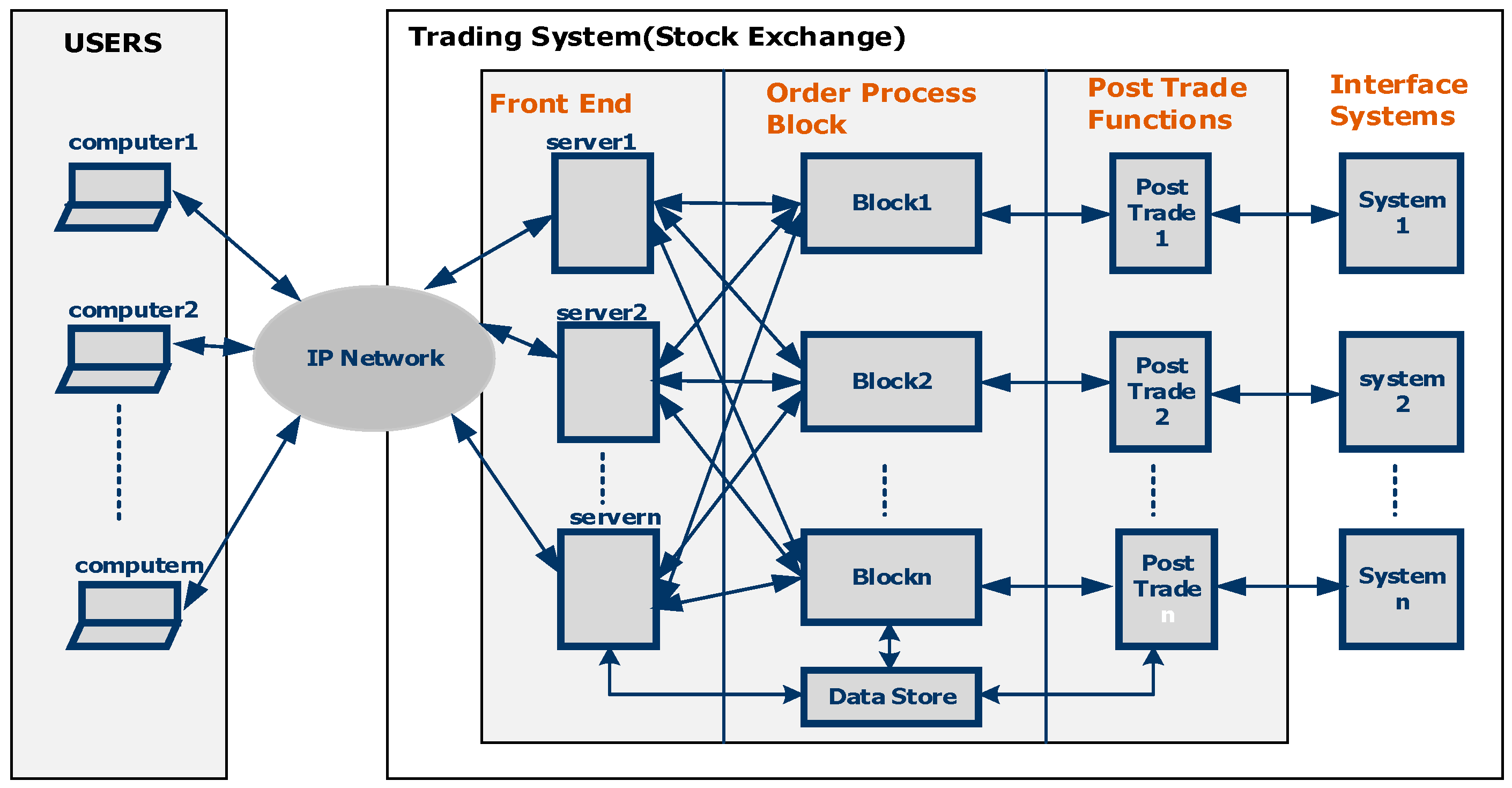
The architecture of a Trading System is depicted in Figure 1. It consists of many users/traders connected to the trading system using an IP-based network. These traders are outside the premise of the trading system.
The Trading System itself consists of front-end, order-matching, and post-trade components. The front-end component receives trade requests from the users on the Ethernet network and performs validations on the ranges of various parameters in a trade request and the functional validations. The order-matching component matches buy orders against sale orders and vice versa. It maintains the database of orders received from traders and executes commands to perform order matching. The post-trade block performs data logging functions after a trade happens and also performs the functions of record keeping, journaling, and sending a response back to the users. Since these functions are implemented in software at present in most trading systems, these systems give a high response time and low throughput for trade requests.
FPGAs are increasingly being used to perform these functions in hardware to reduce latency and increase throughput [15,16]. Front-end and order-matching functions are implemented with PCIe add-on FPGA boards. As mentioned above, the front-end functions involve validations of the numeric ranges of different fields present in the trade requests and also the functional validations. KVS is used mainly for functional validations. An example of functional validation is using a nine-digit social security number to retrieve the identification number (ID) of the user and compare it with the user ID in the database to check if a particular user is a valid user. Since there are approximately 20 million users in our client stock exchange at present and this number is expected to grow to 40 million in the future, our KVS design needs to handle 40 million keys.
Moreover, at present, the rate at which orders are received is 1 million orders/s and this is expected to grow to 4 million orders/s in the future. Therefore, the KVS needs to support up to 4 million search operations/s.
4. Architecture of KVS_Top
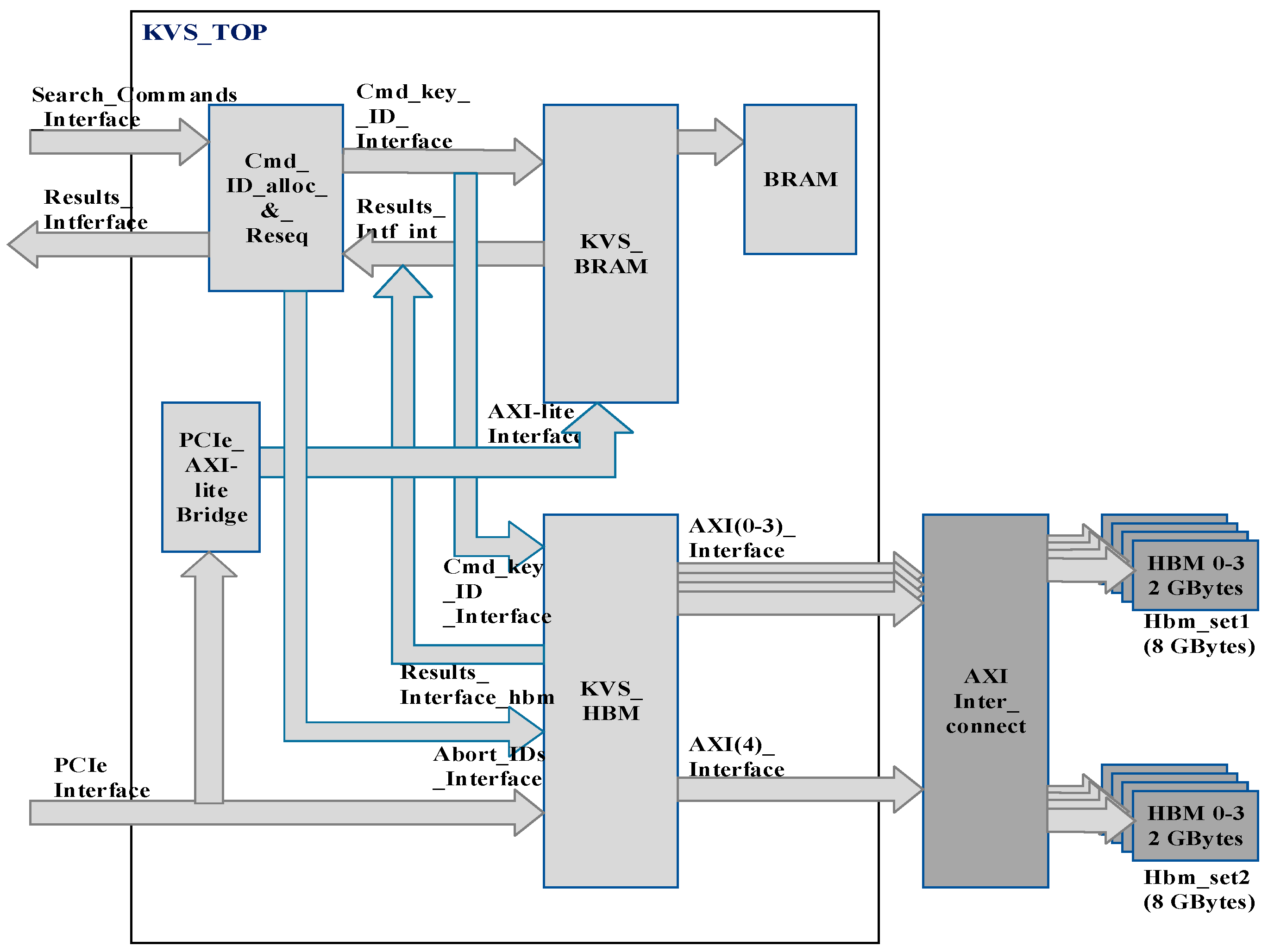
KVS_top is our top-level design, which instantiates both the hash-based lookup engine and B-Tree-based lookup engines. Since our KVS_Top design uses both the BRAM and HBM as stated earlier, the design is partitioned into two main sub-blocks, KVS_bram, which stores the keys in BRAM/UltraRAM, and KVS_hbm, which stores keys in on-chip HBM. KVS_bram executes insert, delete, and search commands in hardware. KVS_hbm executes search commands in hardware while insert and delete commands are issued to KVS_hbm through software by the host. KVS_bram uses hash tables while KVS_hbm uses four lookup engines working in parallel on four B-Tree databases. Four B-Tree databases contain the same data, as explained later.
The top-level block diagram of KVS_Top showing all the interfaces is shown in Figure 2. KVS_Top consists of KVS_hbm and KVS_bram as stated earlier. Search commands are issued to KVS_Top from users submitting trade requests on the Search_Commands_Interface. A search command consists of a Command_code (2-bit) and an input key (128-bit).
Insert and delete commands are issued to KVS_bram and KVS_hbm through the software on the PCIe interface shown in Figure 2. The PCIe_Axi-lite bridge converts the PCIe protocol to AXI-lite for interfacing with KVS_bram. KVS_bram accepts the insert and delete commands on the AXI-lite interface. The Cmd_ID_alloc_&_reseq block allocates a 2-bit Command_ID to each search command. Search commands are supplied to both KVS_bram and KVS_hbm in parallel since it is not known in advance whether a key resides in BRAM or HBM. The search command execution time of KVS_bram is much shorter than that of KVS_hbm. Therefore, if KVS_bram completes the search command successfully as indicated on the internal results interface—Results_intf_int—the Cmd_ID_alloc_&_reseq block commands the KVS_hbm to abort the search command. The abort command is sent to KVS_hbm on the Abort_IDs_Interface by issuing Abort_ID, which is equal to the Command_ID of the command to be aborted, as shown in Figure 2. If the search command is completed with an error status from KVS_bram on the internal results interface, Results_Intf_int, KVS_hbm is allowed to complete the command. The Command_IDs are necessary since the search commands given to KVS_hbm may not be completed in the same sequence in which they are issued. For example, if two search commands, cmd1 and cmd2, are submitted to KVS_hbm in the pipelined manner and the key corresponding to cmd1 is found in level 3 of B-Tree and the key corresponding to cmd2 is found in level 1 of B-Tree, then cmd2 will be completed before cmd1. The Cmd_ID_alloc_&_reseq block re-sequences the command responses so that the results of search command execution are received on the external Results_Interface in the same sequence in which search commands are issued to KVS_Top. As stated earlier, KVS_bram stores the keys in on-chip BRAM, and KVS_hbm stores the keys in BRAM and on-chip HBM. There is 16 GB of on-chip HBM available in the FPGA, which we use for KVS. Sixteen gigabytes of HBM are divided into two sets (hbm_set1 and hbm_set2) of four banks with each bank consisting of 2 GBytes of memory (Refer to Figure 2). Four banks of HBM in one set are accessed by four lookup engines present in KVS_hbm, as explained later. The key database is replicated in all four banks in one set while inserting the keys using the software. Therefore, all four lookup engines work in parallel, giving very high throughput. Since the two sets of banks are connected using an on-chip AXI-Interconnect, each set can be accessed by four lookup engines. When hbm_set1consisting of four banks of 2Gbytes each is accessed by four lookup engines for carrying out search commands, the software writes the insert and delete commands in bulk to hbm_set2 and prepares an alternate database. This is performed in parallel while search operations are carried out by four lookup engines on hbm_set1. When an alternate database is ready, the software sets a flag called bank_flag in a register inside KVS_hbmm and four lookup engines then switch to hbm_set2 to carry out search operations and hbm_set1 will be used to carry out the new insert and delete operations in the software. KVS_hbm accesses two sets of HBM using AXI (0–3) interfaces for search commands and the AXI (4) Interface shown for insert and delete commands issued through software (Refer to Figure 2). It can access both sets of HBM simultaneously due to the presence of AXI-Interconnect. The architecture of KVS_bram and KVS_hbm is explained in detail below.
4.1. KVS_Bram
KVS_bram completely reuses the architecture of the lookup engine designed in our earlier work [17] and uses a hash table and buckets of different capacities as mentioned earlier. In a traditional KVS, which uses hashing, colliding keys are stored in a linked list (called a bucket) pointed to by a hash index. The keys in a linked list need to be sequentially read and compared with the incoming key. Though the usage of a linked list conserves BRAM, it increases search latency and reduces the throughput if the number of colliding keys is very large. To overcome this, our design uses buckets of variable capacity to conserve the BRAM and stores the keys contiguously in a bucket. These keys are read into a pipelined comparator and compared in parallel with an incoming search key to reduce the search latency.
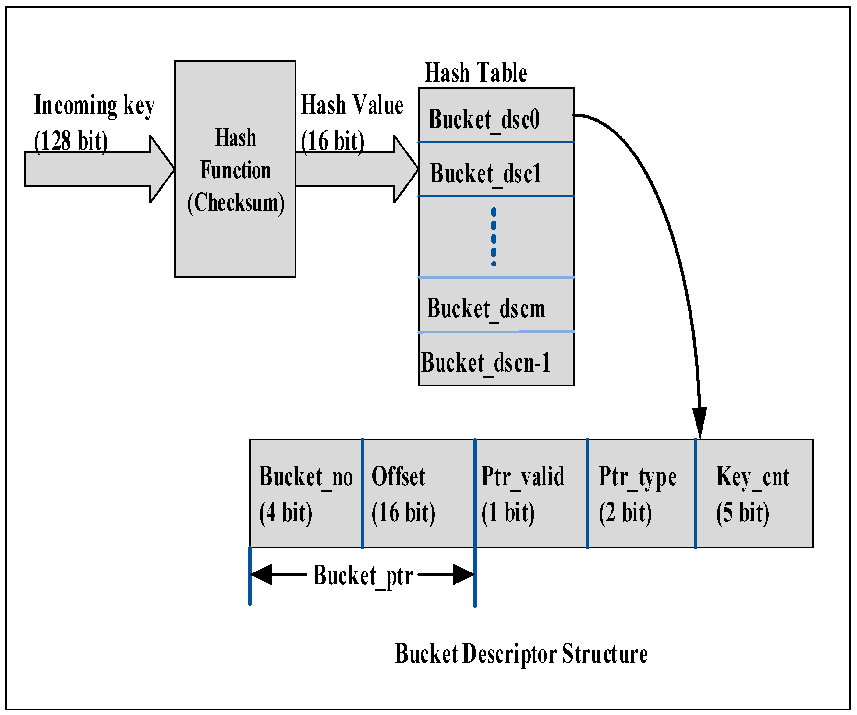
In our design, the 128-bit incoming key is hashed using the checksum algorithm and the resulting hash value is used as an index into the hash table (implemented in BRAM), which is used to store bucket descriptors (Bucket_dsc0—Bucket_dscn-1) as shown in Figure 3. Bucket descriptors in turn contain pointers to the buckets of different capacities containing a differing number of keys. The bucket descriptor structure contains the key count (Key_cnt), pointer valid bit (Ptr_valid), pointer type (Ptr_type), offset of the bucket group (Offset), and bucket number (Bucket_no). The description of these fields is given below:
- Ptr_valid (1 bit)—Indicates contents of bucket descriptor are valid and bucket descriptor holds a valid pointer to a hash bucket containing one or more keys.
- Ptr_type (2 bits)—Indicates the type of hash bucket or capacity of the hash bucket in Block RAM as explained below. Bit 00, 01, 10, and 11 indicate 1-key, 4-key, 8-key, and 16-key buckets, respectively.
- Bucket_ptr (16 bits+ 4 bits)—20-bit pointer to hash bucket pointed to by this descriptor as shown in Figure 3. Bucket_ptr consists of a 16-bit Offset to Bucket Group and 4-bit Bucket_no.
- Key_cnt (5 bits)—Indicates the count of colliding keys in the hash bucket pointed to by the pointer in this descriptor.
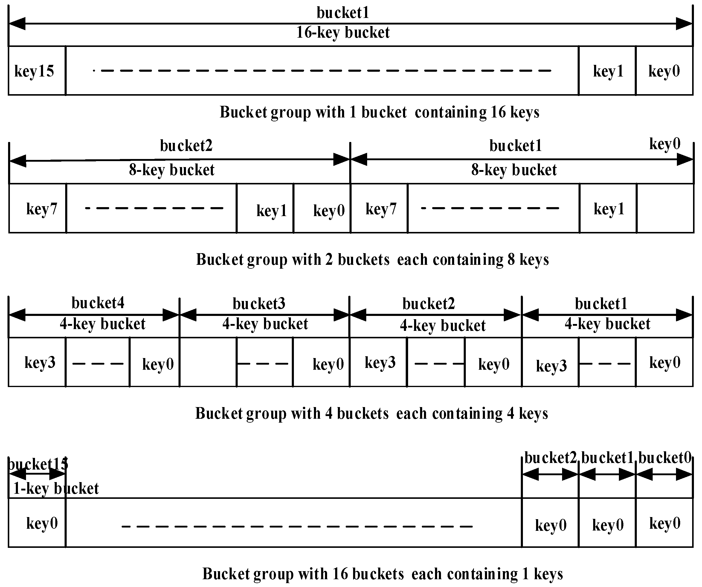
As mentioned above, our KVS design uses buckets of four different sizes to conserve the BRAM, instead of using buckets of fixed lengths. Using buckets of fixed lengths results in wastage of BRAM if the number of colliding keys in the bucket is small. If initially there is only one key in the hash bucket, a bucket size of 1 is used. If one more key hashes into the same bucket during the insert operation, a bucket with a size of 4 is obtained from the free pool of buckets, and the original 1-key bucket is returned to the free pool of buckets. If a 4-key bucket is full and one more key hashes into it, the 4-key bucket is returned to the free pool and an 8-key bucket is obtained from the free pool, and all keys are transferred from the 4-key bucket to the 8-key bucket. Similar logic holds for the 8-key and 16-key buckets. The free pool of buckets is a First-In-First-Out (FIFO), which is initialized at the reset with the pointers to the free buckets. Since buckets are stored in BRAM, which is limited in FPGA, this scheme optimizes the use of BRAM.
Keys are stored contiguously in a hash bucket, and using a pointer in the bucket descriptor, all keys in the hash bucket are read into a parallel comparator in FPGA. The comparator compares all the keys in the hash bucket in parallel with the incoming key and returns the index of the matching key, which is used to access the data corresponding to that key. Parallel comparison gives very low latency, and the pipelined operations of different blocks result in very high throughput.
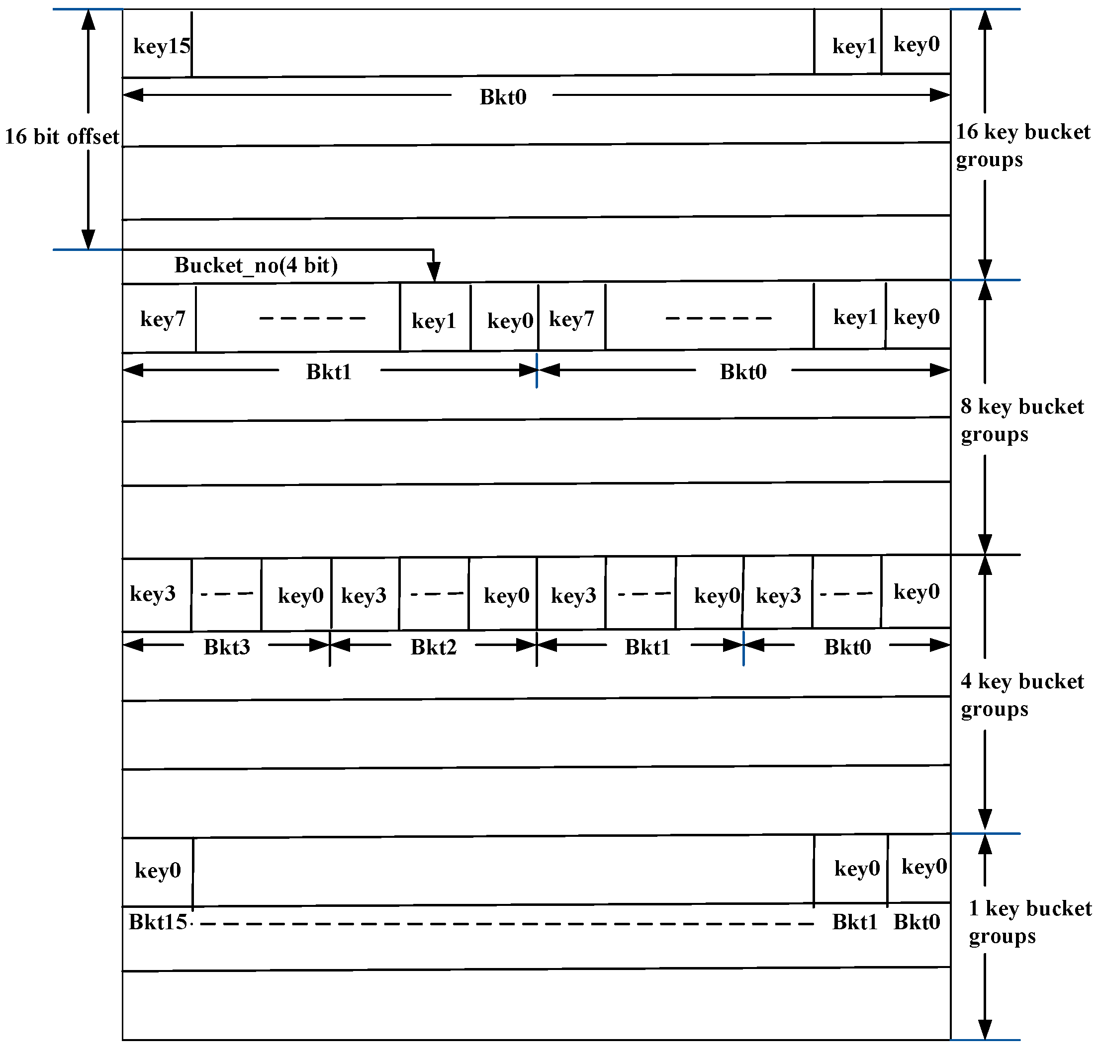
Hash buckets are stored in bucket memory in BRAM, which consists of an array of bucket groups. As shown in Figure 4, each bucket group can consist of one 16-key bucket, two 8-key buckets, four 4-key buckets, or sixteen 1-key buckets, and Bucket memory (Buckt_mem) consists of an array of bucket groups. Thus, a bucket group always contains 16 keys. As each key is 128-bit wide, the width of the bucket group is 2048 bits. Bucket memory is an array of bucket groups of different capacities. As shown in Figure 3, a bucket descriptor contains a bucket pointer consisting of a 16-bit offset (Offset) into bucket memory and a 4-bit bucket number (Bucket_no (3:0)). The interpretation of Bucket_no depends on the type of bucket. For a 16-key bucket, Bucket_no (3:0) has no significance since there is only one bucket present in the bucket group. For a 4-key bucket, Bucket_no (3:2) identifies one out of four buckets present in the bucket group. For an 8-key bucket, Bucket_no (3) identifies one of two buckets. For a 1-key bucket, all four bits of Bucket_no (3:0) identify a bucket number, since there are sixteen buckets and there is only one key in each bucket. Furthermore, 128-bit data corresponding to the keys is also stored in BRAM using a data structure similar to bucket memory (refer to Figure 4 and Figure 5). The BRAM, which stores the data corresponding to the keys, is called data memory. The index returned by the comparator mentioned above is used to access the data corresponding to the search key from data memory. The number of 1-key, 4-key, 8-key, and 16-key buckets is software configurable.
4.1.1. Architecture of KVS_Bram
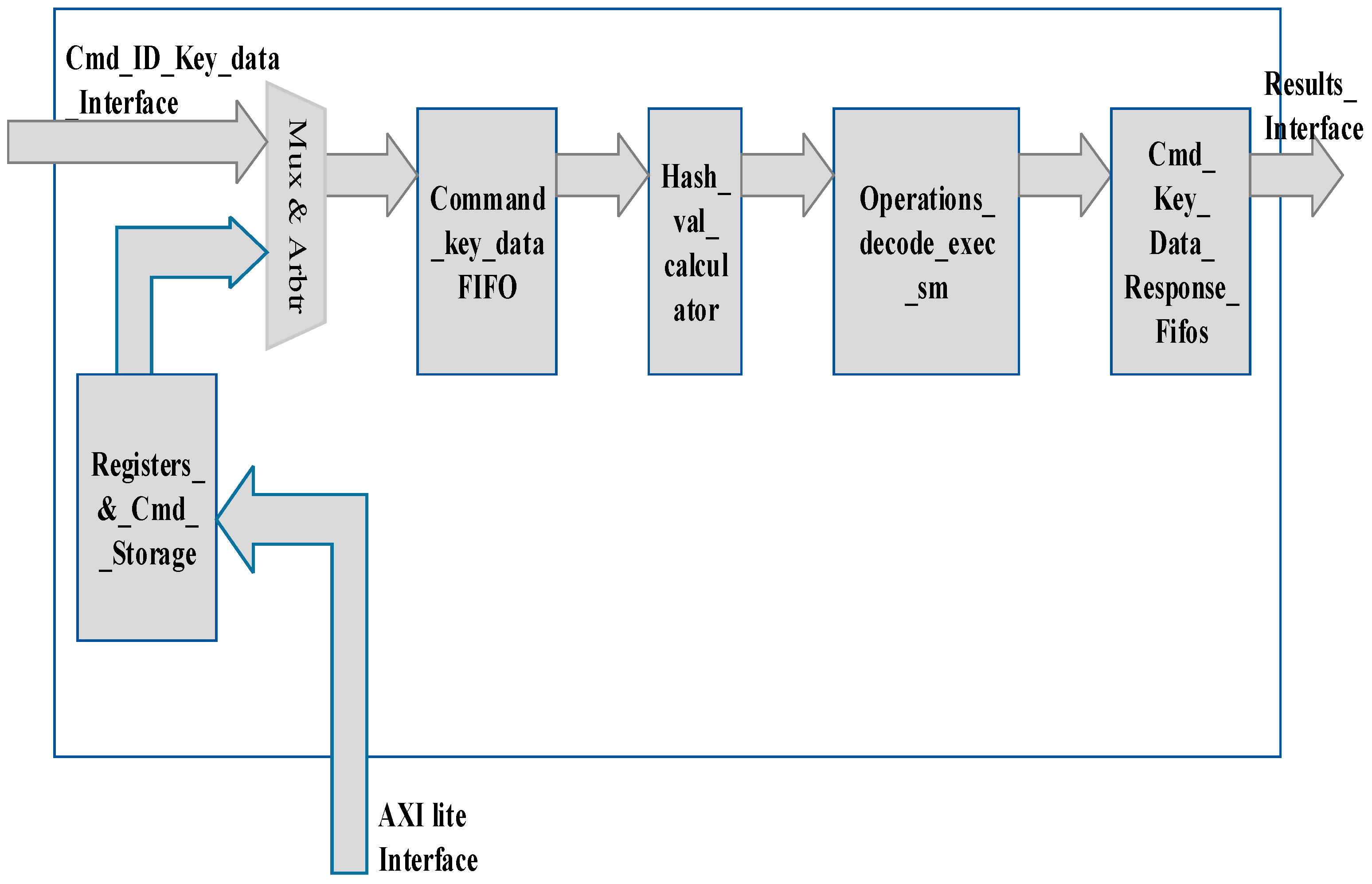
The block diagram of KVS_bram is shown in Figure 6. KVS_bram receives a stream of fixed-length keys (128 bits), Command_code (2 bits), Command_ID (2 bits), and data (128 bits) on cmd_ID_Key_data_Interface and provides key, lookup data, command, and error signals on Results_Interface, as shown in Figure 6. The error signals indicate the success or failure of the command issued on cmd_ID_Key_data_Interface. Different sub-blocks of KVS_bram are described below:
- Command_key_data_ID_FIFO: This FIFO stores a 128-bit key, 128-bit data, and a 2-bit command received on the cmd_ID_key_data_interface. It also stores the 2-bit Command_ID.
- Hash_val_calculator (Hash Value Calculator): The 128-bit key and command are read by Hash_val_calculator, which computes a 16-bit checksum on the 128-bit key. It uses a pipelined architecture and computes a 16-bit checksum in 4 clocks. The output of this module is a 16-bit checksum, the value of the key, Command_code, and Command_ID.
- Operations_decode_exec_sm (Operations Decode Execute State Machine): This block decodes 2-bit Command_code and performs all the operations required to execute the search, insert, and delete commands. In the case of insert and delete commands, new 1-key, 4-key, 8-key, and 16zkey buckets are assigned, and one that is freed is put back in the free pool. In case a bucket of particular capacity is full and one more key hashes into it, a higher-capacity bucket is obtained from the free pool, and this bucket is returned to the free pool. Keys from the freed bucket are transferred to that obtained from the free pool. In the case of a search command, the 16-bit hash value is used as an index in the hash table, which contains bucket descriptors as shown in Figure 3. If the bucket descriptor is valid, 16-bit offset and 4-bit bucket_no are used to load keys from the selected bucket. The keys are loaded into a pipelined comparator, which compares the keys in parallel with the input key and returns an index of the matching key. This index is used to read the data corresponding to the key from data memory.
- Mux and Arbiter—This block multiplexes commands received from the AXI-lite interface and cmd_key_data_interface, as shown in Figure 6.
- Registers_&_Cmd_Storage—This block stores the insert and delete commands received from the AXI-lite interface through software and returns the status of command execution to software.
- Cmd_key_data_response_FIFO—This FIFO stores the data returned for the search command and Command_code along with the key and Command_ID. It also stores the command success/error code.
The algorithmic steps of insert and delete operations are described below.
4.1.2. Insert Key Algorithm
- Read the incoming data and key.
- Compute the hash of the key.
- From the hash value, check whether the allocated bucket type is 1, 4, 8, or 16 key type.
- If (bucket type is type 1) then:
- a.
- If (a new bucket of type 4 is available) then:
- i.
- Copy the keys from the type 1 bucket to the type 4 bucket and add the incoming key to this. Return type 1 bucket to free pool.
- b.
- Otherwise, if (a new bucket of type 8 is available) then:
- i.
- Copy the keys from the type 1 bucket to the type 8 bucket and add the incoming key to this. Return type 1 bucket to free pool.
- c.
- Otherwise, if (a new bucket of type 16 is available) then:
- i.
- Copy the keys from the type 1 bucket to the type 16 bucket and add the incoming key to this. Return type 1 bucket to free pool.
- d.
- Otherwise, store the keys in HBM.
- e.
- End if.
- If (bucket type is type 4) then:
- a.
- If (key count in the bucket < 4) then:
- i.
- add the key to type 4 bucket.
- b.
- If (a new bucket of type 8 is available) then:
- i.
- Copy all the keys from the type 4 bucket to the type 8 bucket and add the incoming key to this. Return type 4 bucket to the free pool.
- c.
- If (a new bucket of type 16 is available) then:
- i.
- Copy all the keys from the type 4 bucket to the type 16 bucket and add the incoming key to this. Return type 4 bucket to the free pool.
- d.
- Otherwise, store the keys in HBM.
- e.
- End if.
- If (bucket type is type 8) then:
- a.
- If (key count in the bucket < 8) then:
- i.
- Add the key to type 8 bucket.
- b.
- If (a new bucket of type 16 is available) then:
- i.
- Copy all the keys from the type 8 bucket to the type 16 bucket and add the incoming key to this. Return type 8 bucket to the free pool.
- c.
- Else:
- i.
- Store the keys in HBM.
- d.
- End if.
- If (bucket type is type 16) then:
- a.
- If (key count in the bucket < 16) then:
- i.
- add the key to type 16 bucket.
- b.
- Else:
- i.
- Copy all the keys from type 16 to HBM and add the incoming key to it. Return type 16 bucket to the free pool.
- c.
- End if.
- Else allocate new 1-key, 4-key, 8-key, or 16-key bucket.
- End.
4.1.3. Delete Key Algorithm
- Read the incoming key and data.
- Compute the hash of the key.
- From the hash value, check whether the allocated bucket type is 1, 4, 8, or 16 key type.
- If the bucket type is 1:
- i.
- Delete the key from the bucket.
- ii.
- Return the bucket to the free pool.
- If the bucket type is type 4:
- a.
- If the key count is greater than 1:
- i.
- Then delete the key from the bucket.
- b.
- Else if the key count is equal to 1:
- i.
- Then delete the key and return the bucket to the free pool.
- c.
- End if.
- Else if the bucket type is type 8:
- a.
- If the key count is greater than 5:
- i.
- Then delete the key from the bucket.
- b.
- Else if the key count is less than 5 and greater than 1:
- i.
- Then if a type 4 bucket is available:
- (1)
- Then copy the keys from the type 8 bucket to the type 4 bucket.
- (2)
- Return the type 8 bucket to the free pool.
- c.
- Else if the key count is 1:
- i.
- If a type 1 bucket is available:
- (1)
- Then move the key from type 4 to type 1 bucket.
- (2)
- Return the type 8 bucket to the free pool.
- d.
- End if.
- Else if the bucket type is type 16:
- a.
- If the key count is greater than 9:
- i.
- Then delete the key.
- b.
- Else if the key count is greater than 4 and less than 9:
- i.
- Then if a bucket of type 8 is available:
- (1)
- Copy the keys from type 16 to type 8 bucket.
- (2)
- Return the type 16 bucket to the free pool.
- c.
- Else if the key count is greater than 1 and less than 5:
- i.
- Then if a bucket of type 4 is available:
- (1)
- Copy the keys from type 16 to type 4 bucket.
- (2)
- Return the type 16 bucket to the free pool.
- d.
- Else if the key count is equal to 1:
- i.
- Then if a bucket of type 1 is available:
- (1)
- Copy the key from the type 16 bucket to the type 1 bucket.
- (2)
- Return the type 16 bucket to the free pool.
- If the key count is zero, then return the bucket to the free pool.
- End if.
- End.
4.2. KVS_hbm
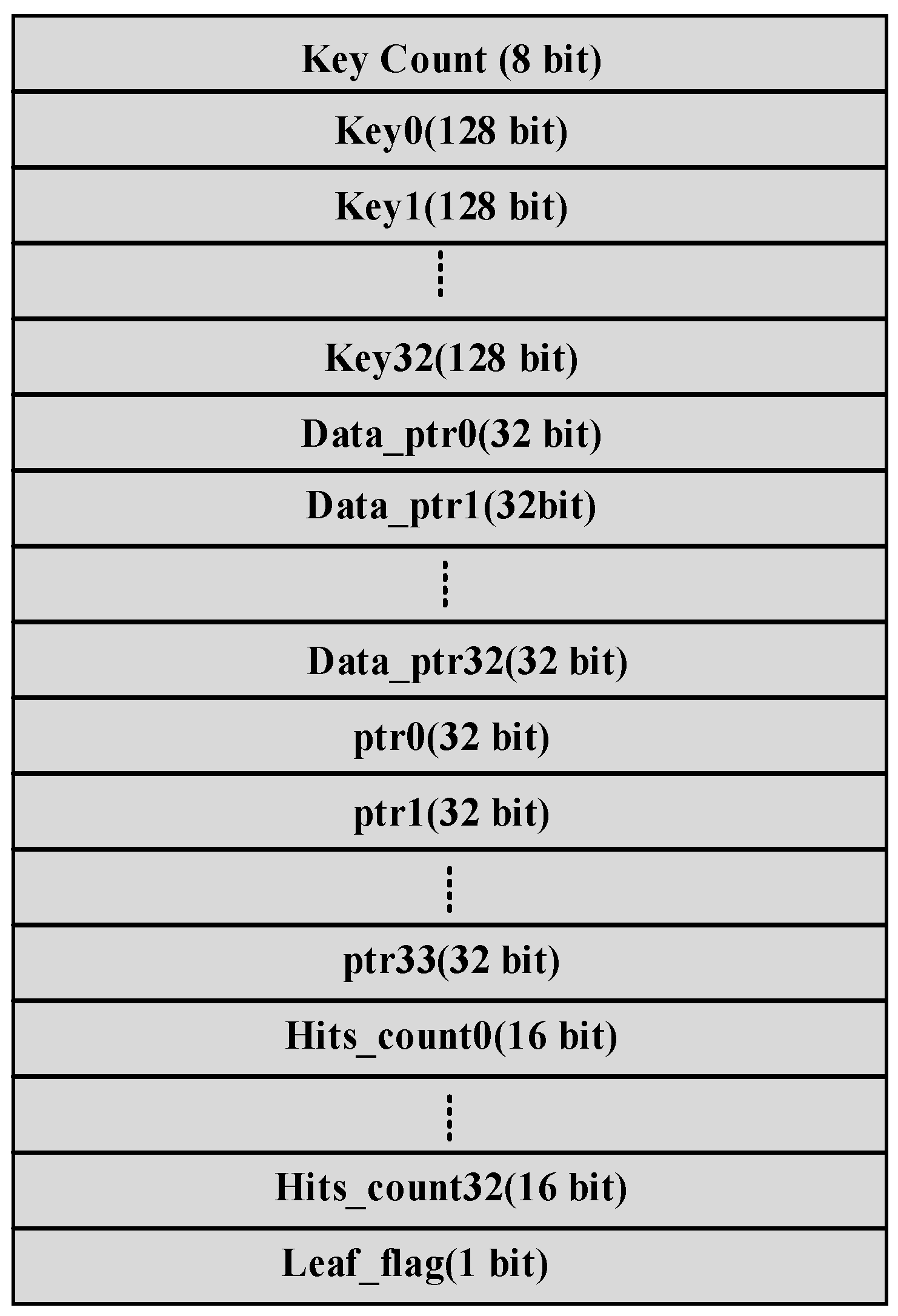
KVS_hbm handles the keys stored in on-chip HBM memory. It uses a 5-level B-Tree for implementing insert, delete, and search operations. Insert and delete operations are implemented in software, while search operations are implemented completely in hardware. The root node of B-Tree and the first two levels are contained in BRAM, while the last two levels are implemented in HBM. The last two levels contain a very large number of nodes and require more storage, so they are located in HBM. The structure of each node of the B-Tree is shown in Figure 7. The node contains an 8-bit count of the number of keys in the node (the maximum number of keys in a node is 33). This is followed by an array of 33 keys (key0–key32) and corresponding data pointers to 33 keys (data_ptr0-data_ptr32). The node also contains 34 pointers to the nodes in the next level (ptr0-ptr33). The hit count denotes the number of times the particular key is hit during a search operation. There are 33 hit counts, Hit_count0—Hit_count32, corresponding to 33 keys. This is used to transfer keys with a large number of hits to BRAM to increase the overall throughput of KVS as explained later. The root node of the B-Tree is located in a register inside FPGA, and the first two levels are implemented in BRAM while the remaining two tree levels are located in HBM. The total number of nodes in the tree is given by the equation:
The total number of nodes = 33 + 33 × 34 + 33 × 342 + 33 × 343 + 33 × 344 = 45,435,423, which is greater than 40 million nodes as per the requirement.
Architecture of KVS_hbm
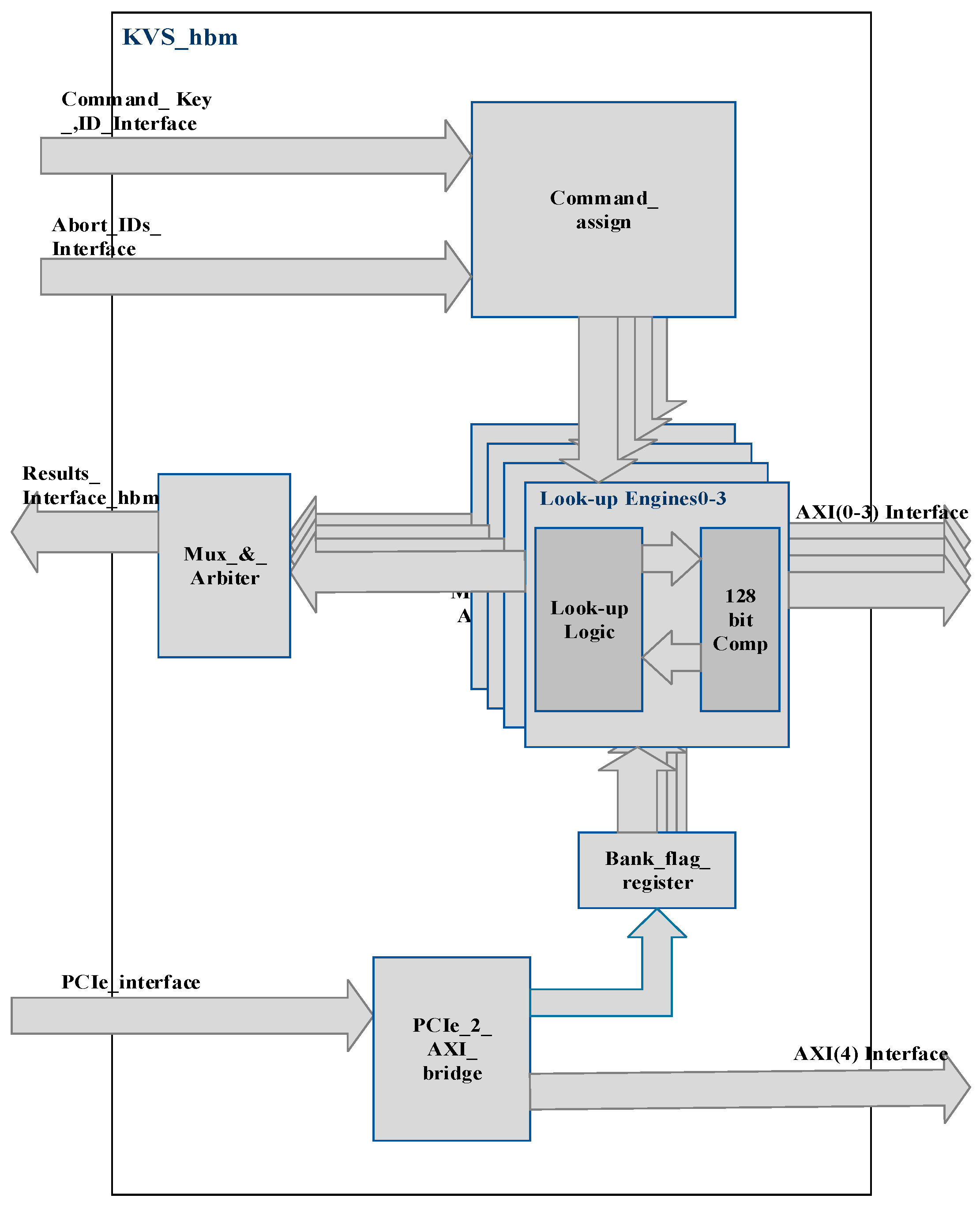
A detailed block diagram of KVS_hbm is shown in Figure 8. KVS_hbm consists of the following sub-blocks:
- Lookup Engines0–3: The four lookup engines work in parallel, and each engine interfaces to 2GBytes of HBM, which contains the key database. The key database is replicated across four banks of HBM connected to four lookup engines by software while executing insert commands. Each lookup engine receives the search command, key, and Command_ID of the command from the Command_assign block. It carries out the search command using a B-Tree. The root node and first two levels of the B-Tree are implemented in FPGA logic while the nodes in the remaining two levels are stored in HBM. The B-Tree nodes contain 33 keys, which are arranged in ascending order. If a key is found in KVS_bram, the Cmd_ID_alloc_&_reseq block issues an abort command with the ID of the search command, which was previously allocated by the Cmd_ID_alloc_&_reseq block, over Abort_IDs_Inteface. The command_assign block then issues the abort command to the respective lookup engine to which the command is assigned, and the search command is aborted. Lookup engines use highly pipelined 128-bit.
A comparator is used to compare the input key with a maximum of 33 keys present in the node of the B-Tree. The comparator returns an index and two flags—equal_flag and right_flag—as a result of the comparison. If the input key is equal to 1 of the 33 keys, the comparator returns the index of the matching key, and equal_flag is set. The index is used to retrieve the pointer data, and using the pointer, data corresponding to the key are read from HBM. If the input key falls between the two keys key(n-1) and key(n), index n-1 is returned and right_flag is set. If the key is less than key(0) in the node, an index of 0 is returned and right_flag is reset. If the input key is greater than key(32), an index of 32 is returned and right_flag is set. Therefore, the comparator returns the index of keys between which an input key lies or the extreme left or extreme right indices. The index is used to retrieve the pointer to the B-Tree node in the next level of the B-Tree. The search operation continues until the matching key is found or the leaf level of the B-Tree is reached as indicated by Leaf_flag (refer to Figure 7). Lookup engines return the lookup result with a success/error status over results_interface_hbm, which is supplied to the Cmd_ID_alloc_&_reseq block.
- 2.
- Comamnd_assign: The Command_assign block receives the search command, input key, and Command_ID over Command_Key_ID_interface. It allocates the command to one of the lookup engines that are free. When a command is assigned to the lookup engine, a busy flag is internally set in the engine, which is reset by the respective engine on completion of the command. The command can be completed successfully or with an error status if the key is not found or an abort command is issued. The Command_assign block also keeps track of which Command_ID is allocated to which Lookup Engine and accordingly issues an abort command to the respective engine on the Abort_IDs_Interface.
- 3.
- PCIe_2_AXI_bridge: PCIe to AXI bridge converts the PCIe protocol to the AXI protocol and is used for issuing insert commands using software to KVS_hbm. PCIe_2_AXI_bridge is also used to access Bank_flag_register, which maintains bank_flag status. Bank_flag indicates which of the set of 8Gbytes HBM (hbm_set1 or hbm_set2) is active at any time, as explained earlier.
- 4.
- Bank_flag_register: This register contains the bank_flag, which indicates whether hbm_set1 or hbm_set2 is active. When hbm_set1 is active, bank_flag is 1 and search operations are carried out on hbm_set1 while insert commands are carried out on hbm_set2. These insert operations are typically performed in bulk. After insert operations are completed on hbm_set2, software resets the bank_flag so that search operations are carried out from hbm_set2 and hbm_set1 is used for carrying out insert operations in bulk. While insert operations are being carried out in hbm_set2, search operations are carried out in parallel on hbm_set1 and vice versa.
4.3. BRAM/HBM Usage for KVS_Top
Each node of the B-Tree requires 864 Bytes of memory storage. Therefore, KVS_hbm requires 3.93 Mbytes BRAM for four lookup engines to store the first three levels of the B-Tree. It requires 1.852 GBytes of HBM for storing B-Tree nodes and 128-bit data corresponding to the keys. KVS_bram requires 30 Mbytes of UltraRAM and 4 Mbytes of BRAM for storing keys, data, and the hash table.
5. Experimental Results
KVS_bram and KVS_hbm were separately synthesized in Xilinx Virtex Ultrascale + VU47P FPGA. Synthesis was performed with Vivado v2021.1. The resource utilization of KVS_bram and KVS_hbm is shown in Table 1 and Table 2, respectively.
5.1. Simulation of KVS_Top
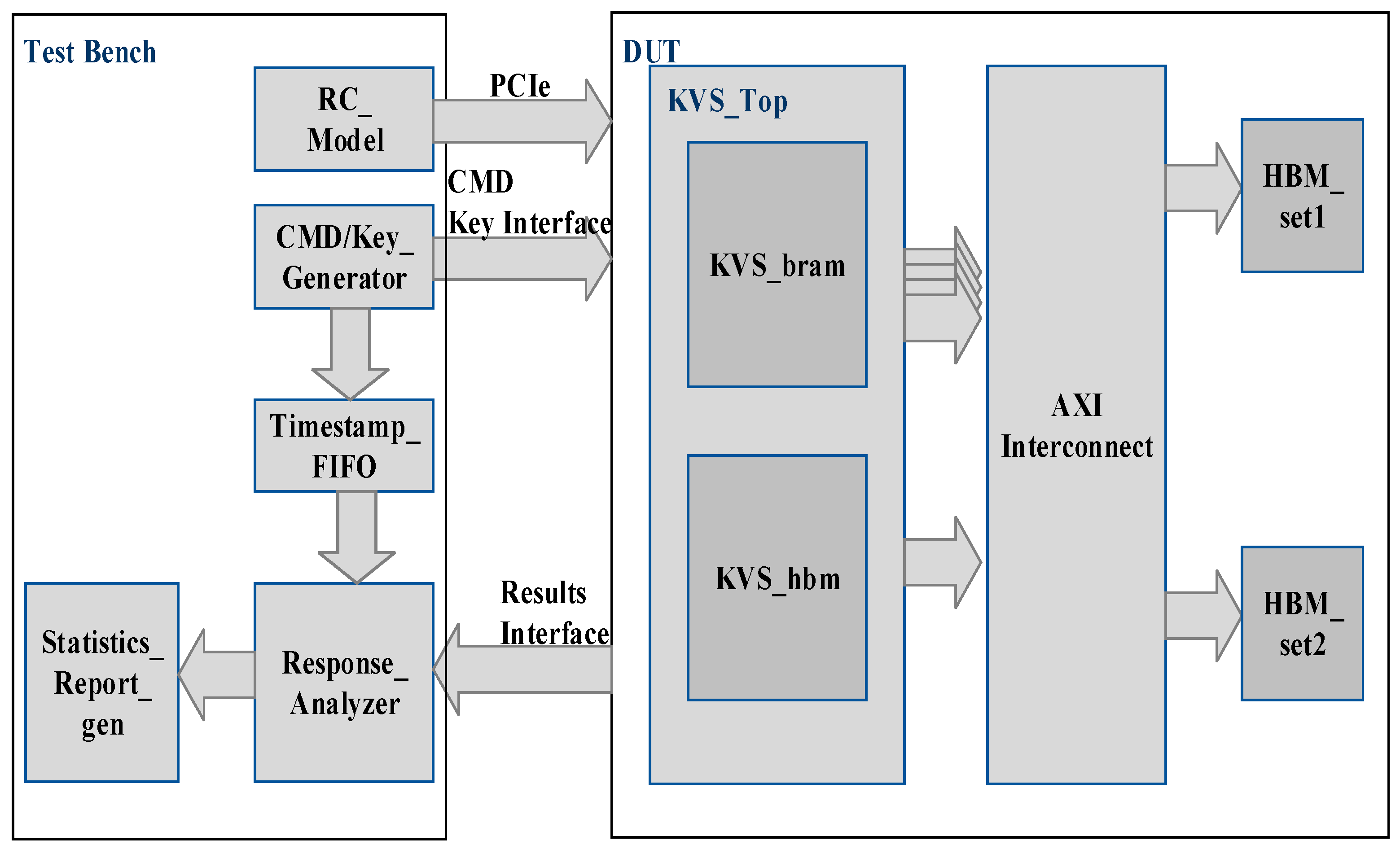
Simulation of KVS_Top was carried out using Cadence Xcelium Single Core simulator version 22.0. The architecture of the test bench used for generating search commands is shown in Figure 9. The DUT (Design Under Test) consists of the Verilog model of KVS_Top and models of AXI-Interconnect and HBM. The test bench consists of the following components:
- CMD/Key_Generator—Generates a 36-bit index randomly. This index is used to look up a table of 128-bit keys stored in the test bench at initialization. The block also generates search commands and sends the key and command to the DUT. The time at which the key and command are sent to DUT is stored in Timestamp_FIFO.
- Timestamp_FIFO—Stores the time at which search commands are delivered to KVS. The Timestamp stored in FIFO is used to find the latency of the search command execution.
- Response_Analyzer—Stores the keys and corresponding data in an Associative array which is initialized with values of 128-bit keys and corresponding 128-bit data before the simulation starts. When the DUT sends a response consisting of a 128-bit key and corresponding data, the key is used to look up an associative array, and the value of corresponding the 128-bit data (expected data) is retrieved from the array. This value is compared with the 128-bit data received in the response from DUT to determine the data integrity. Furthermore, the Response Analyzer notes the time at which the response is received and reads the time at which the corresponding command was delivered to DUT from Timestamp FIFO. The difference between the two timestamps gives the latency of the search command execution. Moreover, the DUT response contains a flag showing whether the response is received from KVS_bram or KVS_hbm. In case a response is received from KVS_hbm, the level at which the key is found in the B-Tree is also recorded. These data are used to find the latency of the search command execution when the corresponding data are found at different levels in the B-Tree.
- Statistics_Report_gen: Maintains the statistics of delay values for SEARCH commands executed by KVS_bram and KVS_hbm. It calculates the average delay values and generates a report of latencies and the throughput of KVS.
- RC_Model: This block is the model of the PCIe Root Complex and generates PCIe read and write commands for sending insert commands to KVS_hbm by software. It also sends insert and delete commands to the KVS_bram through the AXI-lite interface present in KVS_bram.
The test bench operation consists of two phases:
- Initialization Phase—In this phase, BRAM/UltraRAM and HBM memories in the FPGA are initialized with the values of 128-bit keys and corresponding 128-bit data. We have implemented a software function that generates the database of 128-bit keys and data to be inserted into the KVS_bram and KVS_hbm. The function generates the B-Tree nodes in the format shown in Figure 7. It also performs balancing of the B-Tree. The function generates two files for initializing BRAM/UltraRAM and HBM memory.
- Run Phase—In the Run phase, the search, insert, and delete commands are delivered to KVS_bram and KVS_hbm.
5.2. Simulation Results
The KVS_Top was synthesized at the frequency of 300 MHz, and the timings for insert, delete, and search command execution for KVS_bram are given in Table 3.
Average command Execution timings for the search command for KVS_hbm when the key match is found at different levels of the B-Tree are given in Table 4.
5.3. Performance (Search Commands/s) of KVS_Top
The performance of KVS_bram for search commands is 33 million search operations/second. For KVS_hbm, the execution time for the search command depends upon the level at which the key is found. The worst-case performance of one lookup engine is 103/634.2 = 1.58 million search operations/s, assuming the key is found at level 2 in HBM. Therefore, in the worst case, if the key is found at level 4, the performance of KVS_hbm is 1.58 million search operations/s ∗ 4 = 6.32 million search operations/s since four lookup engines are operating in parallel (the performance of one lookup engine is 103/634.2 = 1.58 million search operations/s) since 634.2 ns is the worst-case lookup time. The performance of KVS_Top will depend on the distribution of input keys in the search command.
6. Conclusions and Future Work
In this paper, we present the design of a Key-value Store for a trading system application. By using a combination of Hashing and B-Tree techniques, we can meet the specifications and performance requirements of the stock exchange. To obtain higher performance for active users, we store the key and data corresponding to those users in BRAM/UltraRAM. The KVS_hbm performance can be increased significantly by pipelining the lookup process for different levels of the B-Tree. In future work, we need to design an algorithm that scans the keys in HBM periodically and shifts the keys with a large number of hits from HBM to BRAM/UltraRAM without affecting the throughput of search operations. The number of the keys stored in KVS_bram can also be increased with the use of higher-capacity FPGAs such as Xilinx Versal series FPGAs.
Author Contributions
Conceptualization, S.R. and S.P.; methodology, S.R.; software, M.B.; validation, S.P.; formal analysis, R.P.; writing—original draft preparation, S.P.; writing—review and editing, R.P.; visualization, S.R.; supervision, R.P. All authors have read and agreed to the published version of the manuscript.
Funding
This research received no external funding.
Conflicts of Interest
The authors declare no conflict of interest.
References
- Hauck, S.; DeHon, A. Reconfigurable Computing: The Theory and Practice of FPGA-Based Computation (Systems on Silicon), 1st ed.; Morgan Kaufmann: Burlington, MA, USA, 15 November 2007; ISBN 0123705223. [Google Scholar]
- Available online: https://www.lseg.com/areas-expertise/technology/capital-markets-technology-services/millennium-exchange (accessed on 22 December 2022).
- Hsiue, K.D. FPGA-Based Hardware Acceleration for a Key-Value Store Database. Master’s Thesis, S.B., EECS, Massachusetts Institute of Technology, Cambridge, MA, USA, 2013. [Google Scholar]
- Wiggins, A.; Langston, J. Enhancing the Scalability of Memcached. 2012. Available online: http://software.intel.com/enus/articles/enhancing-the-scalability-of-memcached (accessed on 22 December 2022).
- Qiu, Y.; Xie, J.; Lv, H.; Yin, W.; Luk, W.-S.; Wang, L.; Yu, B.; Chen, H.; Ge, X.; Liao, Z.; et al. FULL-KV: Flexible and Ultra-Low-Latency In-Memory Key-Value Store System Design on CPU-FPGA. IEEE Trans. Parallel Distrib. Syst. 2020, 31, 1828–1844. [Google Scholar] [CrossRef]
- Deepakumara, J.; Heys, H.M.; Venkatesan, R. FPGA implementation of MD5 hash algorithm. In Proceedings of the Canadian Conference on Electrical and Computer Engineering 2001, Conference Proceedings (Cat. No.01TH8555), Toronto, ON, Canada, 4–7 May 2001; Volume 2, pp. 919–924. [Google Scholar] [CrossRef] [Green Version]
- Cho, J.M.; Choi, K. An FPGA implementation of high-throughput key-value store using Bloom filter. In Proceedings of the 2014 International Symposium on VLSI Design, Automation and Test, Hsinchu, Taiwan, 28–30 April 2014; pp. 1–4. [Google Scholar] [CrossRef]
- Ren, Y.; Liao, Z.; Shi, X.; Xie, J.; Qiu, Y.; Lv, H.; Yin, W.; Wang, L.; Yu, B.; Chen, H.; et al. A Low-Latency Multi-Version Key-Value Store Using B-Tree on an FPGA-CPU Platform. In Proceedings of the 2019 29th International Conference on Field Programmable Logic and Applications (FPL), Barcelona, Spain, 8 September 2019; pp. 321–325. [Google Scholar] [CrossRef]
- Bando, M.; Artan, N.S.; Chao, H.J. Flashlook: 100- gbps hash-tuned route lookup architecture. In Proceedings of the International Conference on High Performance Switching and Routing, HPSR 2009, Paris, France, 22–24 June 2009; pp. 1–8. [Google Scholar]
- Sourdis, I.; Pnevmatikatos, D.; Wong, S.; Vassiliadis, S. A reconfigurable perfect-hashing scheme for packet inspection. In Proceedings of the International Conference on Field Programmable Logic and Applications, Tampere, Finland, 24–26 August 2005; pp. 644–647. [Google Scholar]
- Istvan, Z.; Alonso, G.; Blott, M.; Vissers, K. A Flexible Hash Tabke Design for 10GBPS Key-Value Stores on FPGAS. In Proceedings of the 2013 23rd International Conference on Field Programmable Logic and Applications, Gothenburg, Sweden, 31 August–4 September 2020. [Google Scholar]
- Pagh, R.; Rodler, F. Cuckoo hashing. J. Algorithms 2004, 51, 122–144. [Google Scholar] [CrossRef]
- Kirsch, A.; Mitzenmacher, M.; Wieder, U. More robust hashing: Cuckoo hashing with a stash. SIAM J. Comput. 2009, 39, 1543–1561. [Google Scholar] [CrossRef] [Green Version]
- Liang, W.; Yin, W.; Kang, P.; Wang, L. Memory efficient and high performance key-value store on FPGA using Cuckoo hashing. In Proceedings of the 2016 26th International Conference on Field Programmable Logic and Applications (FPL), Lausanne, Switzerland, 29 August 2016; pp. 1–4. [Google Scholar] [CrossRef]
- Boutros, A.; Grady, B.; Abbas, M.; Chow, P. Build fast, trade fast: FPGA-based high-frequency trading using high-level synthesis. In Proceedings of the ReConFigurable Computing and FPGAs (ReConFig), Cancun, Mexico, 4–6 December 2017. [Google Scholar]
- Ding, L.; Yin, W.; Wang, L. Ultra-Low Latency and High Throughput Key-Value Store Systems Over Ethernet. In Proceedings of the 2018 IEEE International Symposium on Circuits and Systems (ISCAS), Florence, Italy, 27–30 May 2018; pp. 1–5. [Google Scholar] [CrossRef]
- Puranik, S.; Sinha, S.; Barve, M.; Patrikar, R.; Shah, D.; Rodi, S. Key-Value Store using High Level Synthesis Flow for Securities Trading System. In Proceedings of the 2020 International Conference on Computing, Electronics & Communications Engineering (iCCECE), Southend Campus, UK, 17–18 August 2020. [Google Scholar]
Figure 1.
Architecture of a Trading System.

Figure 2.
Block Diagram of KVS_Top showing all Interfaces.

Figure 3.
Hash Table and Bucket Descriptor Data Structure.

Figure 4.
Format of buckets of different capacities and bucket groups.

Figure 5.
Key Bucket Memory with Bucket Groups.

Figure 6.
Block Diagram of KVS_bram.

Figure 7.
Structure of a B-Tree Node.

Figure 8.
Detailed Block Diagram of KVS_hbm.

Figure 9.
Architecture of Test Bench for Generating Search commands to KVS_Top.


Table 1.
Resource Utilization of KVS_bram.
| Flip_Flops/ Total/ Utilization | LUTs/ Total/ Utilization | UltraRAM KB/ Total/ Utilization |
|---|---|---|
| 39,192/2,607,360 = 1.503% | 52,037/1,303,680 = 3.99% | 460/960 = 47.92% |
Table 2.
Resource Utilization of KVS_hbm.
| Flip_Flops/ Total/ Utilization | LUTs/ Total/ Utilization | BRAM (MB) Total/ Utilization |
|---|---|---|
| 90,329/2,607,360 = 3.461% | 146,221/1,303,680 = 11.21% | 4.231/8.86 = 47.75% |
Table 3.
Command Execution timings for KVS_bram.
| Sr No. | Command | Timing |
|---|---|---|
| 1 | Insert | 20 |
| 2 | Search | 12 |
| 3 | Delete | 25 |
Table 4.
SEARCH Command Execution time for KVS_hbm.
| Sr No. | Level | Timing |
|---|---|---|
| 1 | 0 (root) | 170.6 ns |
| 2 | 1 | 210.2 ns |
| 3 | 2 | 243.8 ns |
| 4 | 3 | 371.2 ns |
| 5 | 4 | 634.2 ns |
Disclaimer/Publisher’s Note: The statements, opinions and data contained in all publications are solely those of the individual author(s) and contributor(s) and not of MDPI and/or the editor(s). MDPI and/or the editor(s) disclaim responsibility for any injury to people or property resulting from any ideas, methods, instructions or products referred to in the content. |
© 2022 by the authors. Licensee MDPI, Basel, Switzerland. This article is an open access article distributed under the terms and conditions of the Creative Commons Attribution (CC BY) license (https://creativecommons.org/licenses/by/4.0/).
Share and Cite
MDPI and ACS Style
Puranik, S.; Barve, M.; Rodi, S.; Patrikar, R. FPGA-Based High-Throughput Key-Value Store Using Hashing and B-Tree for Securities Trading System. Electronics 2023, 12, 183. https://doi.org/10.3390/electronics12010183
AMA Style
Puranik S, Barve M, Rodi S, Patrikar R. FPGA-Based High-Throughput Key-Value Store Using Hashing and B-Tree for Securities Trading System. Electronics. 2023; 12(1):183. https://doi.org/10.3390/electronics12010183
Chicago/Turabian StylePuranik, Sunil, Mahesh Barve, Swapnil Rodi, and Rajendra Patrikar. 2023. "FPGA-Based High-Throughput Key-Value Store Using Hashing and B-Tree for Securities Trading System" Electronics 12, no. 1: 183. https://doi.org/10.3390/electronics12010183
Note that from the first issue of 2016, this journal uses article numbers instead of page numbers. See further details here.