
A Novel Anchor-Free Localization Method Using Cross-Technology Communication for Wireless Sensor Network †


1
School of Information Science and Engineering, Yanshan University, Qinhuangdao 066004, China
2
Hebei Key Laboratory of Information Transmission and Signal Processing, Qinhuangdao 066004, China
3
Hebei Key Laboratory of Software Engineering, Qinhuangdao 066004, China
*
Author to whom correspondence should be addressed.
†
This paper is an extended version of our paper published in IEEE ICPADS 2021, Beijing, China, 14–16 December 2021: International Conference on Parallel and Distributed Systems under the title “Anchor-Free Self-Positioning in Wireless Sensor Networks via Cross-Technology Communication”.
Electronics 2022, 11(23), 4025; https://doi.org/10.3390/electronics11234025
Submission received: 20 October 2022
/
Revised: 21 November 2022
/
Accepted: 23 November 2022
/
Published: 4 December 2022
(This article belongs to the Special Issue Wearable Sensing Devices and Technology)
Abstract
:In recent years, wireless sensor networks have been used in a wide range of indoor localization-based applications. Although promising, the existing works are dependent on a large number of anchor nodes to achieve localization, which brings the issues of increasing cost and additional maintenance. Inspired by the cross-technology communication, an emerging technique that enables direct communication among heterogeneous wireless devices, we propose an anchor-free distributed method, which leverages the installed Wi-Fi APs to range instead of traditional anchor nodes. More specifically, for the asymmetric coverage of Wi-Fi and ZigBee nodes, we first design a progressive method, where the first unknown node estimates its location based on two Wi-Fi APs and a sink node, then once achieving its position, it acts as the alternative sink node of the next hop node. This process is repeated until the new members can obtain their positions. Second, as a low-power technology, ZigBee signal may be submerged in strong signal such as Wi-Fi. To overcome this problem, a maximum prime number is deployed to be the Wi-Fi broadcasting period based on the numerical analysis theory. Among many of prime numbers, we have the opportunity to select an appropriate one to achieve full coverage with the relatively small packet collisions. Last, simulations and experiments are performed to evaluate the proposal. The evaluation results show that the proposal can achieve decimeter level accuracy without deploying any anchor node. Moreover, the proposal demonstrates the anti-interference ability in the crowded open spectrum environment.
1. Introduction
In the past decade years, with the deep integration of Internet of Things (IoT), 5G (fifth-generation), Artificial Intelligence (AI), Edge Computing (EC), Block Chain (BC), etc., [1] Wireless Sensor Network (WSN) has again attracted the attention of industry and academia, playing an increasingly vital role in the fields of automated agriculture, national defense security, environmental monitoring, forest carbon sink, disaster rescue, and smart home [2], etc. In most WSN applications, the information collected by sensors is based on the location of nodes [3,4]. For instance, the location of the incident needs to be confirmed urgently when pollution or fire occurs. The corresponding strategy cannot be deployed without the specific coordinates of the nodes [5]. Therefore, it is crucial to know the exact location of the sensor node where events occurred or located for most WSN applications [6].
The most common solution to position is the anchor-based approach [7]. Localization is carried out utilizing the available position of the Anchor Nodes (AN) and the information interaction between AN and unknown nodes. According to whether the distance or angle between nodes needs to be calculated, there are two approaches toward AN-based localization: range-based method [8] and range-free method [9].
Common range-based schemes include Time of Arrival (ToA) [10] and Time Difference of Arrival (TDoA) [11], Differential Time Difference of Arrival (DTDoA) [12] and Equivalent Differential Time Difference of Arrival (E-DTDoA) [13]. These are generally preferred time-based ranging schemes. For the abundant hardware of the sensor node, the antenna array can be deployed to measure the Angle of Arrival (AoA) [14], with which the orientation of the target can be calculated. On the contrary, for the resource-constrained commodity ZigBee devices, Received Signal Strength Indicator (RSSI) is the best way to measure the distance between the transceivers [15]. Owing to easy acquisition, RSSI based methods are widely used in many indoor localization systems. The classic RSSI-based localization scheme is trilateration localization [16], which requires the locations of at least three known beacons to position the target. In order to further improve ranging accuracy, RSSI is combined with the Channel State Information (CSI) parameters to achieve multi-dimension hybrid measurements, because CSI has higher granularity than RSSI to reveal more detail about wireless channel, such as RSSI-AoA [17], ToA-RSSI [18], multiple parameters [19,20], etc. Additionally, both RSSI-based and CSI-based considers the fingerprint algorithm [21], which requires an offline training process and the dataset of fingerprints collected by anchor nodes, as known as a “Radio Map”. Fingerprint algorithm estimates the likely location of the target by comparing collected data with the reference data.
The alternate and cost-effective solution is the range-free approach, which utilizes proximity measurements without any additional hardware and knowledge about distance or angle. The popular range-free schemes include the Centroid algorithm [22], DV–Hop [23], amorphous algorithm [24], approximate point-in-triangulation (APIT) [25] and Multidimensional Scaling (MDS) [26], PHL-based approach for anisotropic WSN [27]. Compare to the range-based schemes, range-free methods do not need the prior knowledge of ANs. However, the localization accuracy of range-free techniques deteriorate correspondingly. Therefore, tradeoff between the two localization techniques has to be considered.
The aanchor-based location algorithm is mature and has been widely deployed. However, the research on anchorless positioning started relatively late with fewer results, and most of them only stay at the level of algorithm design and have not been applied in practice. Although anchor-based schemes have higher accuracy, they are highly dependent on the number and the position of ANs. Moreover, regular maintenance of the ANs is also required, which leads to cost, maintainability and scalability issues. Anchor-free positioning schemes can reduce the cost and complexity without the need to pre-deploy the anchor nodes, especially in some special applications. For example, the locations of all nodes in a WSN are random and cannot be obtained in advance, or it could be used in dangerous areas where humans are unable to reach. Therefore, the anchorless location algorithm is of great importance to the field of WSN location.
The earliest anchor-free location algorithm is the ABC (assumption based coordinates) algorithm [28], which establishes the positioning order based on the communication connection between nodes and estimates the position in turn. ABC is easy to implement, but it has a large positioning error, so it is often used as an auxiliary positioning method. The AFL (anchor-free localization) algorithm [29] obtains a fold-free network model to obtains approximate estimated coordinates. However, the AFL algorithm is not fully distributed. According to the principle of multidimensional scaling, anchor-free localization can be achieved [30], but it is centralized. The GFF (GPS-free-free) algorithm [31] uses the hops from nodes to anchor nodes as the distance. GFF is a coarse-grained location algorithm with simple calculation and low hardware requirements, but large positioning error. It is generally used for initial location estimation of network deployment. In [32], the individual sensors use knowledge of received beacons and information from nearest neighbors to identify the sub-sectors in which they reside. KPS (deployment knowledge based positioning system) [33] is based on a probabilistic model of group placement. KPS has low communication overhead but is only suitable for static WSN. The possibility of using image registration techniques to achieve localization is investigated in WSN [34], but it is only applicable in case of nodes equipped with video sensors. The above are several classical anchor-free WSN localization algorithms, and their common problem is that the poor localization accuracy.
Although the existing positioning algorithms have been well developed in the past two decades, they are far from the application requirements:
- Improving coverage. Limited by the low power, a sensor device can only achieve about 20 m transmission. In order to enlarge the coverage, a large quantity of ANs has to be deployed. Except for the unacceptable cost, deployment of a large number of ANs will increase the complexity and maintenance of the network.
- Anti-interference. In indoor scenarios with complex radios, as the lower-power device, sensor is vulnerable to interference from the signals with strong-power, such as Wi-Fi and Bluetooth.
- Avoiding packet collisions. ANs have to broadcast their locations and identities in WSN to enable the ZigBee Node (ZN) to be aware of their positions. When a large number of ANs is connecting, WSN suffers from packet collisions.
Fortunately, Cross-Technology Communication (CTC) has emerged and flourished to solve the coexistence and spectrum efficiency problem among the heterogeneous devices, which has attracted many attentions both in industry and academia [35,36]. CTC is significant for the scalability, availability and reliability of the diverse IoT.
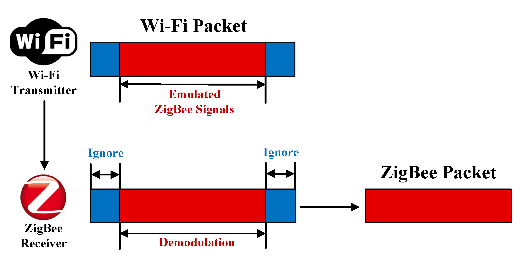
The key challenge for CTC is to deal with the heterogeneity among devices caused by the diversity of IoT, including incompatibility of communication standards and asymmetry of communication and computing power. The existing works are divided into packet-level CTCs and physical-level CTCs. Early works on CTC are packet-level CTCs. It manipulates packet and encodes certain channel parameters as the carrier to convey messages for transmissions, such as packet energy, packet length and timing [37]. These packet-level methods are relatively easy to be accessed. However, their communication efficiency, quality, and throughput are extremely low. In addition, the asymmetry of the communication protocols results in a large amount of wasted bandwidth. Physical-level CTCs can effectively alleviate the limitations of packet-level CTCs, physical-level CTCs emerge as the times require. WEBee [36] is the first Wi-Fi-to-ZigBee physical-level CTC technology. Figure 1 illustrates the architecture of WEBee, where the ZigBee time domain waveform is emulated by redesigning the payload of the Wi-Fi packet on the sending side. When the ZigBee node receives these choreographed signals, the header, preamble, and trailer of Wi-Fi packets are ignored as noise, then the Wi-Fi payload is recognized as a legitimate ZigBee packet. The ZigBee nodes can demodulate the heterogeneous transmitters’ signals without any hardware modifications. Following WEBee, quantity of physical-level CTC technologies is emerging to improve communication performance and address the emulation errors [37,38,39].
Inspired by CTC between Wi-Fi and ZigBee, we propose a novel WSN self-positioning method by leveraging the installed Wi-Fi infrastructure to achieve distance calculation instead of traditional ANs in WSN, named as Wi-Fi based ZigBee nodes Localization (WiZiLoc [40]). Specifically, first, two Wi-Fi APs and a Sink Node (SN) is deployed to locate the one-hop node. Any ZigBee node can be considered as the one-hop node once it accesses the intersection area of the two Wi-Fi APs and SN. When one-hop node gets positioned, it becomes the reference of the next Unknown ZigBee Node (UZN). Second, two Wi-Fi APs and the positioned one-hop node are used to locate the next hop UZN, which is not located in the mentioned intersection area. The first and second step is repeated until the new members can achieve their positions. Finally, in order to avoid the signal conflicts caused by the strong Wi-Fi signal due to the crowded unlicensed spectrum (e.g., ISM bands), we design a proper Wi-Fi broadcasting period to send CTC packet based on a numerical calculation, where the broadcasting period is set to a maximum prime number. Through WiZiLoc, ZigBee nodes can overcome the hardware limitations and access a larger coverage, meanwhile, the number of the ANs decreases dramatically with only a few Wi-Fi APs.
In summary, our contributions is outlined as follows:
- For the first time, we apply the advanced CTC technique to WSN localization. Instead of anchor-based localization, we propose an anchor-free mechanism by leveraging the installed Wi-Fi infrastructure to calculate the distance.
- We design WiZiLoc, a distributed self-positioning method for localization in WSN. To achieve this, we face two challenges, including the asymmetric coverage and the strong interference introduced by the environmental Wi-Fi. A distributed progressive method and a reasonable Wi-Fi broadcasting period are investigated to address the challenges.
- We implement WiZiLoc on the SDR platform USRP N210 and the commodity ZigBee device, CC2530. The experimental results demonstrate that WiZiLoc can achieve decimeter-level accuracy within two Wi-Fi APs coverage area, without deploying any ANs.
2. Preliminaries
2.1. Overview
As shown in Figure 2, WiZiLoc are composed of two Wi-Fi APs, an SN and several UZNs, where W and W denote the Wi-Fi APs, UZN to UZN denote k UZNs accessing to WSN. Specifically, W and W deploy WEBee and send CTC packets periodically. Therefore, all UZNs in the coverage area of W and W can successfully receive CTC packets. During positioning with two Wi-Fi APs, an artifact is introduced, we eliminate the artifact by utilizing an SN.
SN is a special ZN. It is responsible for data aggregation and fusion. Additionally, it saves and uploads data to the server. However, as for the normal ZN, its communication distance is below 20 m. Limited by the SN coverage ability, UZNs are divided into two groups. One group is located within the intersection area of W, W and SN, shown as the green dotted circle in Figure 2. In this intersection area, the UZNs can receive packets not only from W and W, but also from the SN. We call such UZNs one-hop nodes. The other group lies in the coverage area of W and W, but locates outside the coverage radius of the SN (outside the green dotted circle). These UZNs cannot receive the packets sent by the SN, but they are still able to receive from other UZNs. We name them as multi-hop nodes.
According to the above discussions, obviously, the premise of WiZiLoc is that there must be an intersection of the coverage areas of W, W and SN, and there at least is a one-hop node (denoted by UZN) in this intersection.
2.2. Challenges
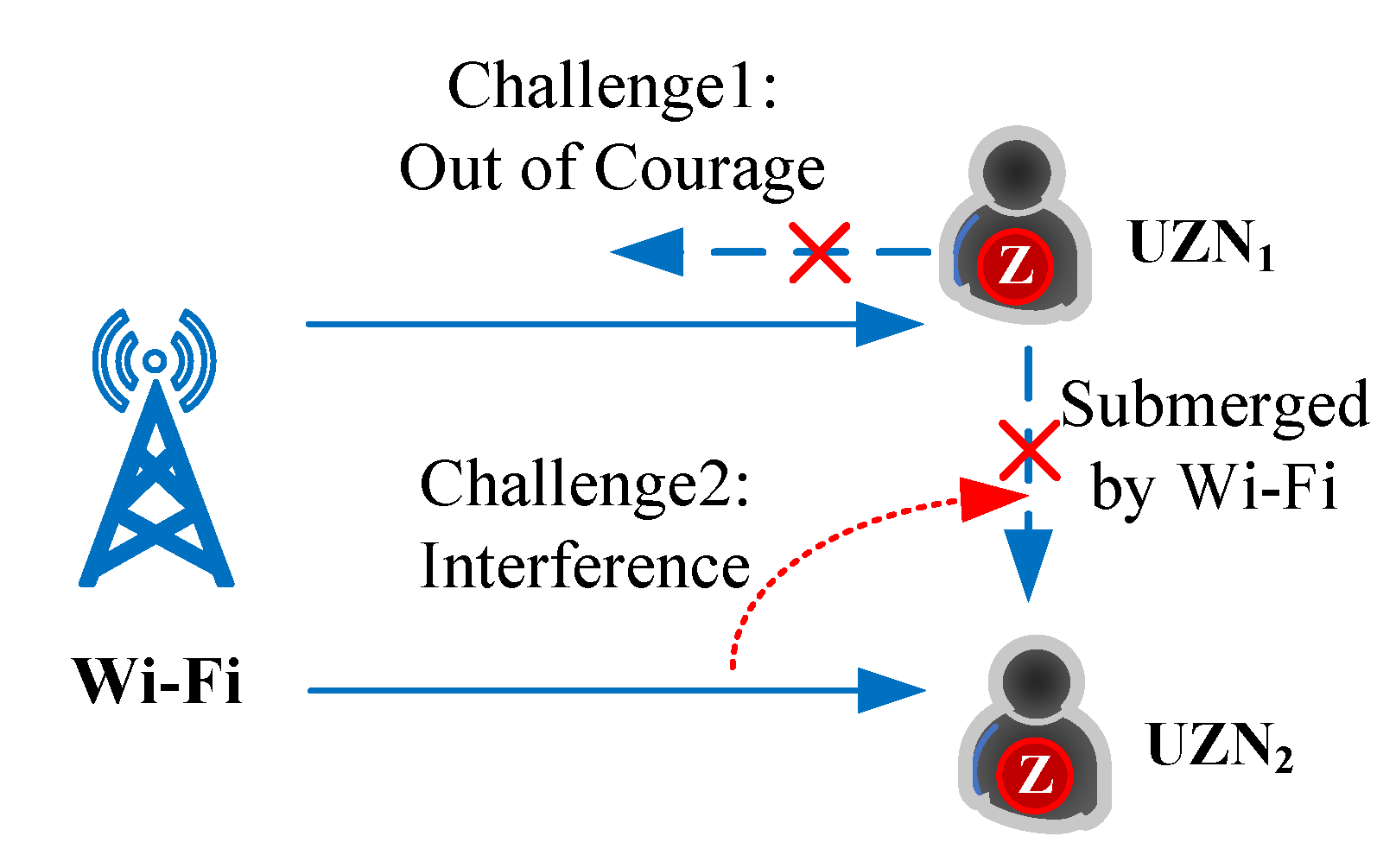
To achieve WiZiLoc, we have to face the following challenges, as shown in Figure 3. Challenge 1, the asymmetric coverage caused by the discrepant transmission power between Wi-Fi and ZigBee. In terms of the standard 802.11 and 802.15.4, the coverage of Wi-Fi signal is up to 200 m, while that of ZigBee is only around 20 m. That means ZigBee node UZN can hear Wi-Fi, however the Wi-Fi is deaf to UZN. As a result, the conventional centralized location methods fail to work. Although the distributed methods may be employed to solve the above problem, these methods only achieve that by use of a large amount of ANs. Therefore, communication from UZN to Wi-Fi without any help of ANs is still challenging.
Challenge 2, in this paper, Wi-Fi APs replace the ANs in ZigBee WSN positioning system and therefore form a heterogeneous network. The strong and weak devices in the heterogeneous network will inevitably affect each other. Compared with the strong Wi-Fi signal, ZigBee signal is weak. The communications among UZNs in WSN are easily submerged and interfered with by the environmental installed Wi-Fi infrastructures. In order to demonstrate the impact from the Wi-Fi interference on the ZNs communications, we conduct several experiments to evaluate the communication performance of UZN receiving CTC signals in heterogeneous networks.
We carried out the following experiments in an indoor barrier free environment: when one Wi-Fi AP sends CTC signals to communicate with UZN, another Wi-Fi AP sends Wi-Fi signals as interference. BER (bit error rate) and PRR (packet reception rate) of UZN are recorded to measure the performance. Both CTC technology used (WEBee) and the traditional Wi-Fi AP adopt IEEE 802.11 g. We tested BER and PRR with the same transmission power at different distances of the transmitter and receiver. As shown in Figure 4, the communication performance of ZigBee WSN deteriorates rapidly, where the BER goes up sharply and the PRR declines to 0.3 when the distance is beyond 7 m. In addition, we also present the physical-level CTC performance in the presence of the Wi-Fi interference for comparison. Compared with WSN communication, CTC can obtain lower BER and more stable PRR at the same distance, physical-level CTC outperforms the conventional ZigBee WSN, which also demonstrates the superiority of substituting the ANs in traditional WSN with Wi-Fi. Thus, the interference introduced by the environmental installed Wi-Fi is another challenging task.
3. WiZiLoc Design
3.1. Workflow
Workflow of WiZiLoc is depicted in Figure 5. The system is divided into three units: Wi-Fi unit, SN unit and UZN unit. The signal transmission direction between the three units is indicated by the dotted arrow line. The key works in this paper are marked with a red dotted line.
In the Wi-Fi unit, at first the physical-level CTC signal is constructed through WEBee [36]. The working principle of WEBee is briefly outlined here: WEBee does not modify the header and tail of the Wi-Fi frame, but simulates a complete ZigBee frame through the payload part of the Wi-Fi frame. It can be correctly received and decoded by ZigBee node. The coordinates and identity information of the Wi-Fi AP are loaded into the CTC signal.
After receiving the CTC signal, UZN unit performs RSSI ranging and calculates its own coordinates according to the ONION algorithm, which we discuss next. Additionally, the corresponding environmental factors is calculated offline. In addition to the auxiliary positioning function, SN unit can also collect and summarize the system data, update the location information of nodes in the network in real time.
Finally, WSN usually adopts the sleep and wake-up mode alternatively to save energy consumption. Inspired by that, we redesign a broadcasting period for Wi-Fi APs, which is explored next. It can not only reduce interference to ensure the internal communication quality of WSN, but also guarantee that all the UZNs are covered, none of which is missed.
3.2. ONION Algorithm
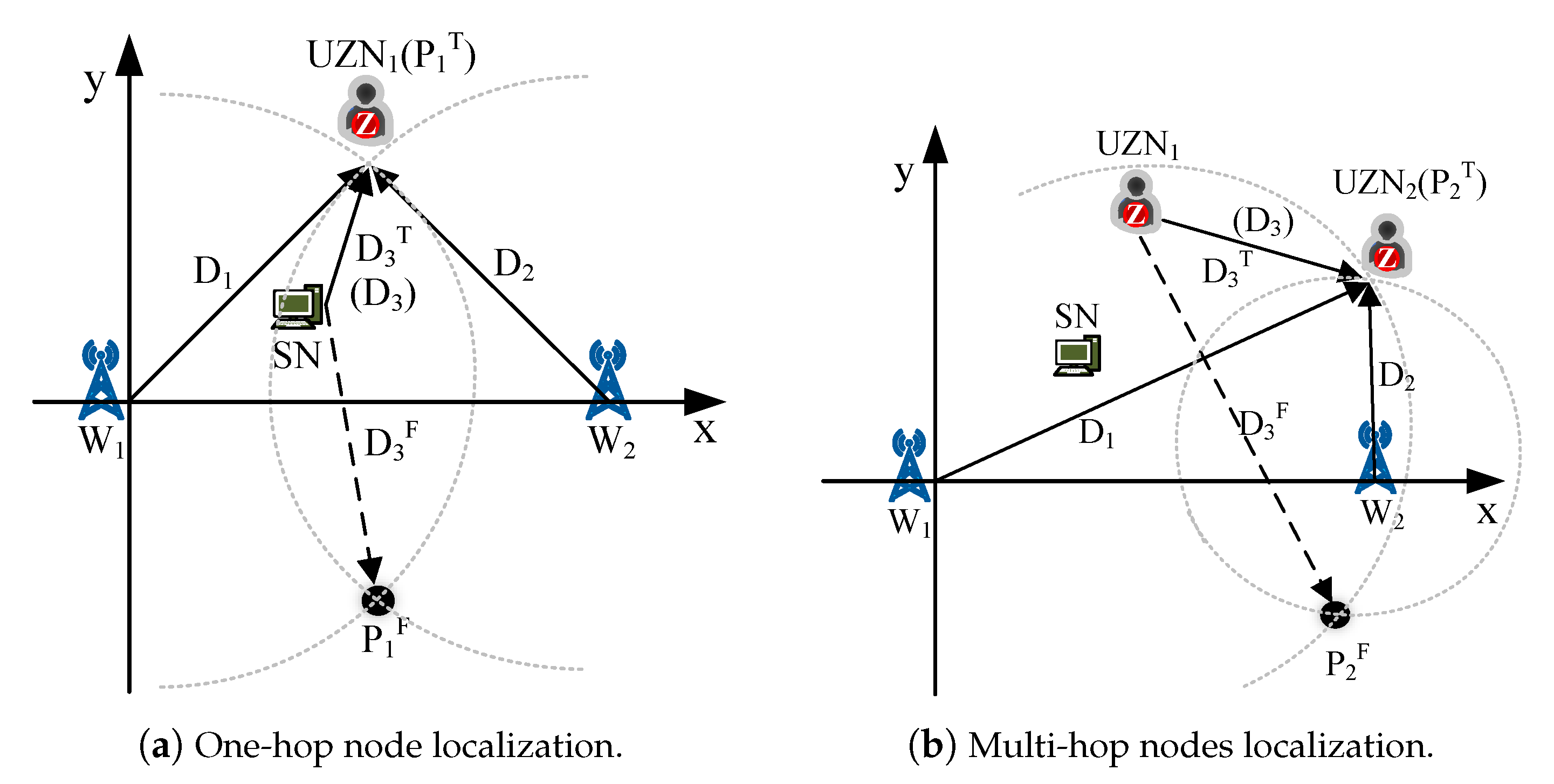
WiZiLoc is composed of two Wi-Fi APs, one SN and the UZNs. According to the one-hop node and multi-hop node, the procedure is conducted in two steps: one-hop node positioning and multi-hop node positioning, as shown in Figure 6.
First, we use two Wi-Fi APs and a SN to position the one-hop node. To facilitate analysis, we assume that the coverage of the SN is intersected with that of W and W, and there is only one one-hop node accessing to this intersection area. If there are multiple one-hop nodes, they are equal in localization. For the one-hop node, due to the CTC packets is also the legitimate ZigBee frame, thus one-hop node can receive and demodulate the CTC packets and calculate its coordinate with Wi-Fi APs locations and identities contained by these CTC packets. However, two Wi-Fi APs will give two coordinates for one target, one of which is the pseudo coordinate, and we call it the artifact. In order to eliminate the artifact, we use a SN to detect the true one-hop node coordinate. UZN can also receive ordinary ZigBee signals from SN, so the trilateration method can be implemented to obtain the coordinates of UZN.
Second, since the two-hop node is outside the coverage of the SN, once one-hop node gets its coordinate, it acts as the SN, and then floods its coordinate into the network. Meanwhile, the second-hop node UZN, that can access to the SN only via forwarding by the one-hop node, calculates its coordinate in terms of the coordinates of W and W, and removes the artifact based on one-hop node. In the same manner, all multi-hop nodes, that cannot directly access the SN, eliminate their artifacts by utilizing the previous hop node. We define such progressive computing procession as ONION algorithm, which is investigated in this subsection.
3.2.1. Basic Idea of ONION
ONION is proposed to address the asymmetry problem of the communication range between Wi-Fi and ZigBee. Intrinsically, ONION is a distributed self-positioning method, and its basic idea is presented in Figure 6.
It can be seen from Figure 6 that the Cartesian coordinate system is established to model the WiZiLoc, where W lies in the origin and W is in the positive x-axis, the SN is located in the upper half. The ONION algorithm is implemented in two steps: the first step is to calculate the coordinates of one-hop nodes, the second step is to calculate the coordinates of multi-hop nodes. To make ONION easy to understand, we assume that there is only one one-hop node accessing to the SN, denoted by UZN, and only one second-hop node connecting to UZN, represented by UZN.
The trilateration algorithm based on RSSI is to reach the coordinates of the unknown point by the coordinates of three known single points. The RSSI value of the signal from the unknown point to these three points can be used to calculate distance. After obtaining the distance from the unknown point to the three known points, the rest is to solve the coordinates of the unknown point. We know that two circles will intersect at one or two points (if they intersect), then if three circles intersect, they must intersect at one point (when the centers of three circles are on a straight line, it is possible to intersect at two points, which is not considered here). Therefore, the unknown point we need to calculate is exactly the intersection of the three circles drawn with the three known points as the center and the distance between them and the unknown point as the radius.
However, our proposed approach is slightly different. We use two known points (i.e., W and W) to get two intersecting circles to obtain two possible coordinates, and then use the distance from the third known point (SN) to remove the artifact. According to the Pythagorean theorem, the formula for calculating the position of the unknown point is obtained, and the problem of positioning is transformed into the problem of finding the coordinates of the intersection of the circles. Figure 6a demonstrates the first step. UZN calculates the distances from UZN to W, W and SN via the RSSI of the received signal, denoted as D, D, D respectively. Then UZN calculates two possible coordinates P and P according to (1), where P is the correct coordinate of UZN, while P is the artifact, illustrated by black solid circles in the Figure 6.
where i represents the i-th UZN, and denote the horizontal and vertical coordinates of UZN. Particularly, for UZN, . is the x-coordinate of W.
Then the correct coordinate of UZN is achieved according to (2).
where and are the horizontal and vertical coordinates of SN. Let
where is the distance between P and SN, is the distance between P and SN. Obviously, is definitely smaller than . Hence the true coordinate P can be distinguished from the artifact P. Similarly, when UZN is in the negative half of the y-axis, the artifact can still be removed by this method because is still smaller than .
Figure 6b illustrates the second step. Whether there are one or multiple one-hop nodes in the coverage area, once UZN achieves its coordinate, it floods its coordinate immediately. Although UZN is located outside the coverage area of SN, it can receive the coordinate of UZN, W and W. Same as the first step, UZN can calculate D, D, D, P and P, D and D respectively. According to (1) and (2), UZN can obtain its correct coordinate. It can be seen from the UZN positioning process, UZN acts as the SN of UZN, and so on. Each multi-hop node can only hear the adjacent previous hop node that has been located, multi-hop nodes can eliminate their artifact by treating the previous hop node as the SN.
3.2.2. Inherent Error of ONION
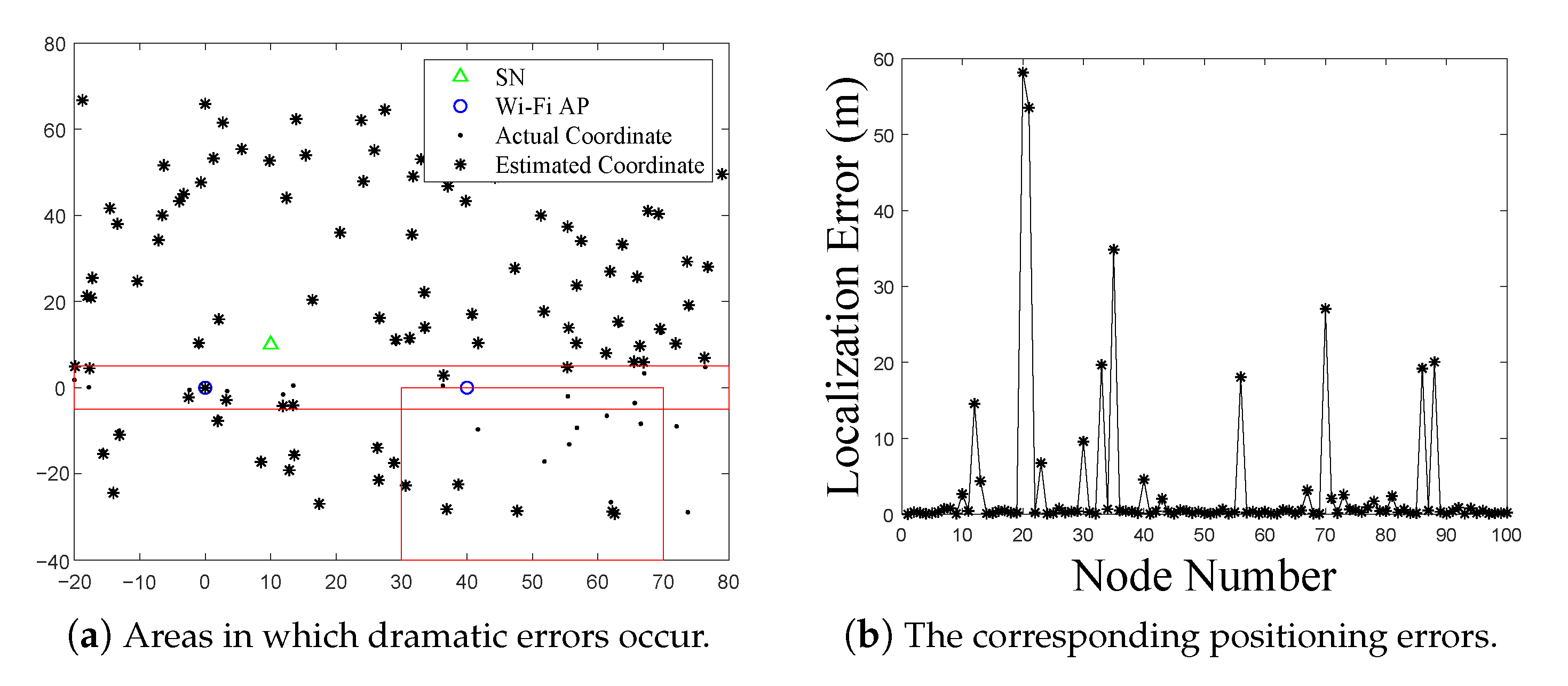
However, we find that the positioning error increases suddenly when UZN is around the x-axis in terms of implementing a large number of simulation experiments. We deploy 100 UZNs in an area of 10,000 square meters for evaluations, and the simulation results are shown in Figure 7. Figure 7a is the simulation map with an area of 100 × 100 square meters. The x-axis is length and the y-axis is width, while the origin is Wi-Fi AP W.
Only when the black dot (the actual coordinate of the node) and the star dot (the estimated node coordinate) are completely coincident, the localization is accurate. It can be seen from the two red boxes marked in Figure 7a that the positioning accuracy in these two areas decreases dramatically, which concentrate around the x-axis and the lower right corner. It also can be found from Figure 7b that the maximum error is up to 60 m. The two areas occurring errors are referred to as inherent errors of ONION.
Intrinsically, the first area, around x-axis, is the stable error region, which means serious positioning errors must be occurring as long as UZN is located in this area. The second area varies randomly around the first area because the next hop node positioning is dependent on the previous hop node coordinate. If the previous hop node is inaccurate, the next hop node is wrong inevitably. Unfortunately, such errors are accumulative. To address the above problem, we first analyze the causes of the inherent errors, then the improvement schemes are explored as follows.
Around the x-Axis
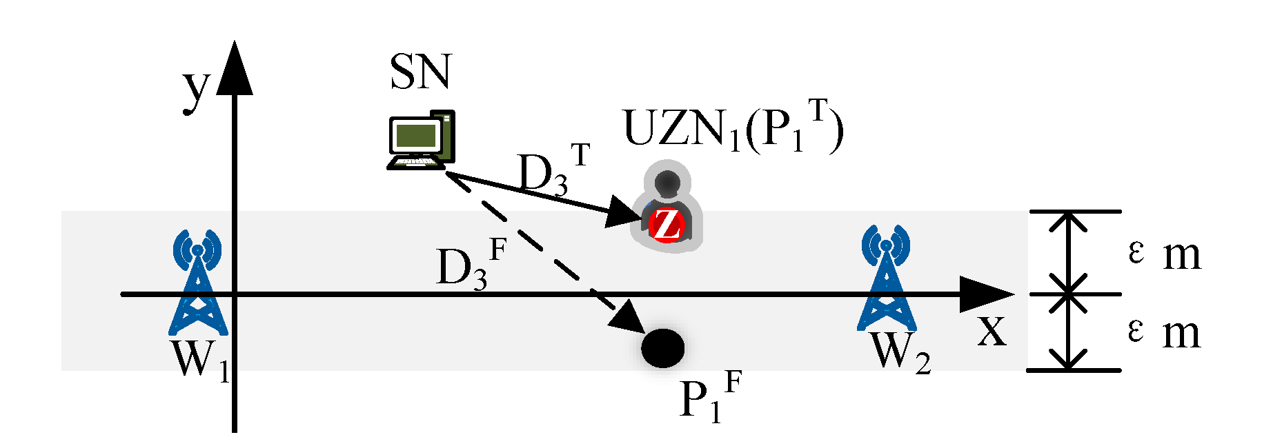
As shown in Figure 8. The values of D and D are very close when UZN is located around the x-axis. WiZiLoc adopts RSSI to calculate the distance, as we know, RSSI is easily disturbed by the environmental noise. Hence, it is difficult to distinguish the P and P for UZN. To solve this problem, we stipulate that as long as the positioning coordinates estimated by UZN are within m around the x-axis, UZN is considered to be on the x-axis.
In the actual indoor environment, when calculating the environmental factor, the interference and multipath effect at different distance d are complicated, and thus their impact on the RSSI measurement is also different. Therefore, under different environments and calculation trajectories, is also different. In this paper, the CDF (cumulative distribution function) of localization error under different environmental factor and calculation trajectories is obtained by analyzing the actual experimental results, as shown in Figure 9. The average value of path 1 is 0.8 m, so is also taken in the simulation experiment to achieve the minimum positioning error. It is worth noting that after switching scenarios and environments, should be determined according to the actual statistical data.
Random Areas near the First Area
If P is considered to be the current correct coordinate of UZN and flooded to the network, it will enable UZN mistakenly use P as the true coordinate of the previous hop node, then P is considered as the current correct coordinate of UZN. As shown in Figure 10, P is a wrong coordinate, which causes P of UZN is also wrong. By parity of reasoning, errors keep accumulating and eventually cause the algorithm to fail to work. To address this problem, in the rectangular coordinate system shown in Figure 10, WiZiLoc chooses the previous hop node with the largest vertical coordinate to be the SN for the next-hop node. This has the advantage of extending the coverage, meanwhile, ensuring to reduce the inherent error due to that the next-hop node is as far away from the x-axis as possible.
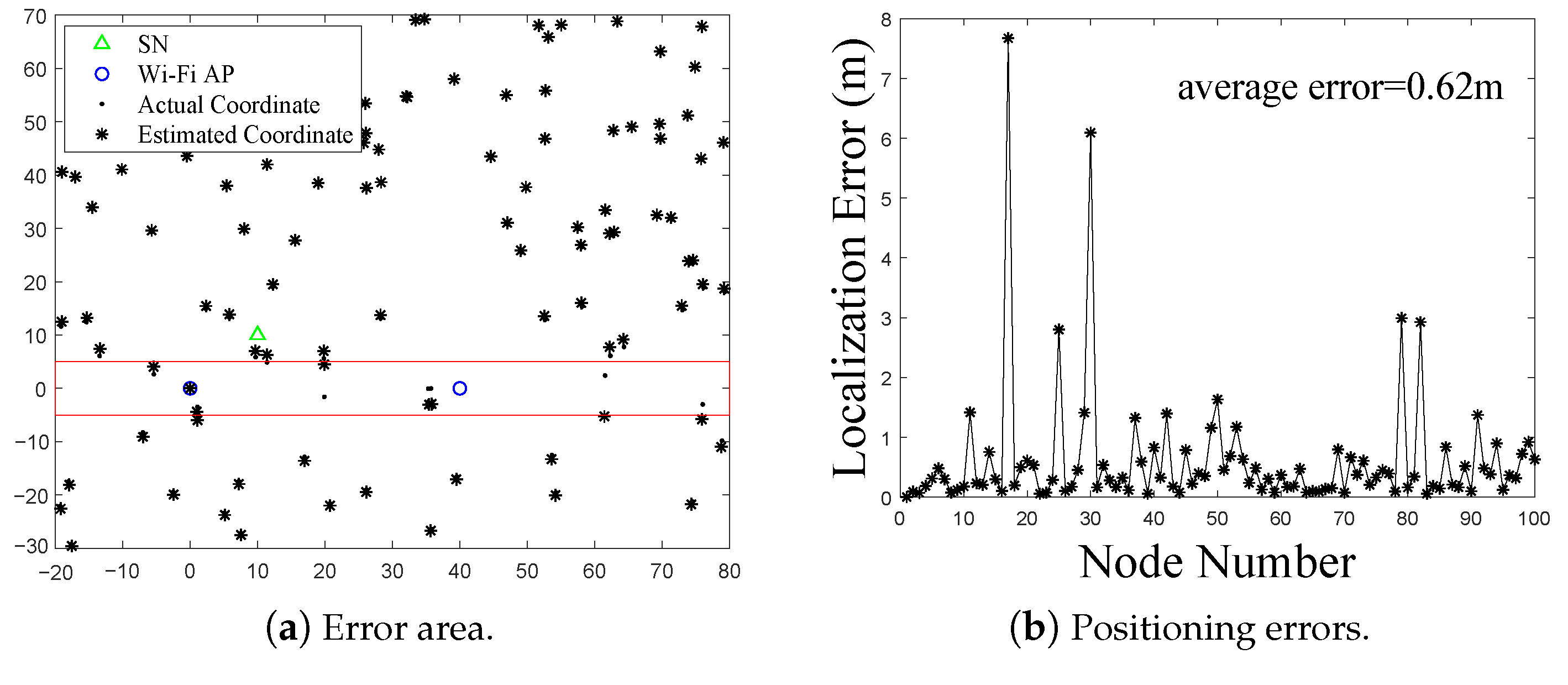
We modify the ONION according to the above analyses, and the corresponding experimental simulation results are shown in Figure 11. After averaging the positioning errors of all 100 nodes, the average error is only 0.62 m. The enhanced ONION algorithm greatly suppresses the inherent errors and improves the average positioning accuracy of WiZiLoc. In summary, the process of the ONION algorithm is shown in Algorithm 1.
| Algorithm 1:ONION |
 |
3.3. Broadcasting Period
In this section, we comprehensively discuss the relationship between the broadcasting period of Wi-Fi AP and the wake-up period of ZigBee. Then we design the Wi-Fi broadcasting period according to the discussion to address the second challenge: the weak ZigBee is vulnerable to strong Wi-Fi interference.
As wearable equipment, ZigBee devices usually use batteries to provide energy, so its power management is a crucial issue. To save energy consumption, ZigBee devices adopt a sleep-and-wake-up mechanism when waiting for transmission. The main goal of the sleep-and-wake-up mechanism is to keep the connection between the ZigBee devices and the network while reducing the energy consumption of the waiting ZigBee nodes.
Due to the sleep-and-wake-up mechanism, the Wi-Fi broadcasting period must be carefully designed. WiZiLoc requires ZNs to receive both CTC packets from Wi-Fi APs and ZigBee packets separately at their wake-up times, which needs to schedule the broadcasting period of Wi-Fi APs to keep synchronizing with the wake-up period of ZNs. Otherwise, the whole network communication performance may be degraded.
If the broadcasting period is consistent with the wake-up period, ZNs cannot receive any ZigBee signal except the CTC packets. If the broadcasting period is selected randomly, the ZNs may not receive any CTC packets. Furthermore, if the Wi-Fi broadcasting period is too short, the 2.4 GHz frequency band will be continually occupied, causing interference to the communication within the network.
In order to solve the above problem, a reasonable broadcasting period of Wi-Fi APs is requisite. The broadcasting period needs to be synchronized with the specific wake-up time to avoid occupying all the wake-up times of the ZNs and jamming communications among ZNs, in the meantime, to ensure all ZNs in the network can receive the CTC packets.
Therefore, in order to reduce packet collisions and ensure the communication quality between UZNs, the principle for designing the broadcasting period is that the broadcasting period is as large as possible within a certain range. Therefore, it is assumed that the broadcasting period is not less than the wake-up period. Furthermore, since when the larger of two numbers is prime, the two numbers must be coprime. This is also the reason for our assumption, which will be discussed later.
We now comprehensively discuss the relationship between the broadcasting period and the wake-up period in several cases, and design how to select the broadcasting period according to their relationship. As shown in Figure 12, we introduce a time axis model, set the start time of a certain broadcasting period as the origin of the coordinate axis, the time unit as , the moment when UZN enters the network as , the broadcasting period as T, and the wake-up period of UZN as , there are . The downward black solid arrow indicates the times when Wi-Fi broadcast CTC packets. The upward gray dotted arrow is the moment when ZNs is awakened. Only when they coincide can UZN receive CTC packets.
- Case 1
T is a multiple of , i.e.,
if , that is, , then obviously only when the wake-up time and the broadcast period coincide, i.e.
can ZigBee receive the CTC signal, and only the CTC signal can be received, which means no extra space left for ZigBee signals. If waking up at other times, ZigBee cannot receive any CTC signal.
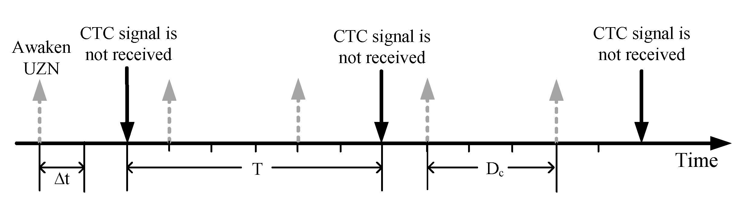
If , we will use an example to illustrate. As shown in Figure 13, the broadcasting period of Wi-Fi AP broadcasting is , the wake-up period of ZNs is . Similarly, the signal can be successfully received only when the wake-up period and the broadcast period coincide. Therefore, there is no guarantee that every UZN can receive the CTC signal in this case.
- Case 2
T is not a multiple of and T and are not coprime. We set
where q is the quotient and r is the remainder. Since T and are not coprime, we set the greatest common divisor of T and as
In this case, we analyze only when is at some specific moment, i.e.,
where e, f, g are all natural numbers.
Under this circumstance, the signal can be received successfully only when the network access time is an integer multiple of the wake-up period , the remainder r or the greatest common divisor . Obviously, when is equal to an integer multiple of or r, the wake-up period and the broadcast period T will always coincide after several periods, i.e., the signal is received. When , since when two numbers are divided by their greatest common divisor, the obtained quotients must be relatively prime which causes CTC signal must be able to be received at some moment in the future. The reason for coprime is also the third case we will discuss next.
- Case 3
T and are relatively prime. Now we will prove that when T and are relatively prime, no matter what the network access time is, the wake-up period and the broadcast period can always coincide, i.e., to prove that there are m and n to make
established. Among them m and n are both integers. In other words, after ZigBee enters the network at , after m wake-up periods , it may coincide with n broadcasting periods T.
Since T and are relatively prime, it can be known from the Euclidean Algorithm that there must be two integers i and j such that
We let
then the formula can be workable. In conclusion, when T and are relatively prime, ZigBee must be able to receive the CTC signal after m wake-up periods.
Obviously, since T and are relatively prime, there is no common factor other than 1 for T and , so the greatest common divisor is 1, namely
According to the theorem: The product of the greatest common divisor and the least common multiple of two numbers is equal to the product of these two numbers, which is proved next.
Let there exist two numbers called x and y, and the greatest common divisor of them .
Then their least common multiple is given as
hence the greatest common divisor and the least common multiple of these two numbers
The proof is done. In combination with this theorem,
we have
which means ZigBee received CTC signals every time units.
When the larger of two numbers is prime, these two numbers must be coprime. Therefore, we only need to set T as a prime number, and it is greater than the wake-up periods of all ZigBee nodes in the network (different ZigBee nodes may have different wake-up periods), then no matter when the UZN accesses the network and no matter what it has, UZN can receive CTC data broadcast by the Wi-Fi AP at a specific wake-up time. Moreover, to prevent too many signal collisions between CTC signal and UZN signal, T is designed as the largest prime number among the wake-up periods of ZNs, we set T to be
where is the wake-up period of the i-th ZN in the network. The reason why we don’t set is to avoid that in some extreme cases (Case 1), Wi-Fi may happen to synchronize with some ZigBee nodes completely, thus affecting the communication of the ZigBee system.
With the help of the prime number design, we ensure that all of the UZN can receive CTC signals while allowing enough time for ZigBee network communication without the Wi-Fi interference at other wake-up times.
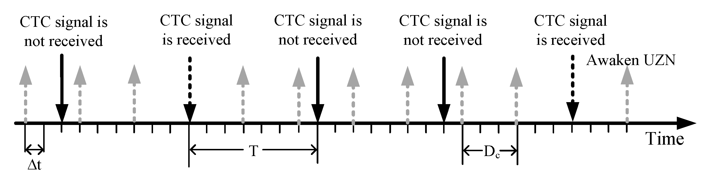
An example of a prime number-based Wi-Fi broadcasting period is shown in Figure 14, where , . The downward black dotted arrow is the moment when the CTC packets are received by UZNs. It can be seen from the Figure 14 that whenever UZN enters the network, it can receive the CTC packets at some instants, while many spare wakeup times remain to enable ZNs communicate with each other without being interfered by CTC packets.
3.4. Offline Part
The RSSI ranging in the ZigBee WSN localization system uses a standard logarithmic attenuation model as shown in (17)
where is the RSSI value of the signal received when the distance between the transceivers is d, is the RSSI when the distance is , usually m, and n is the environmental factor. First, we use the given , d and their corresponding RSSI to calculate n. n is a constant when the environment does not change. Subsequently, we measure d with n in terms of the (17).
As the MAC layer information, RSSI describes the overall characteristics of signals received from multiple paths. As we know, the amplitude and phase of each path will change with the environment, and the RSSI will change accordingly. The complex and variable multipath environment enables RSSI extremely unstable, which is reflected in n in the RSSI measurement model (17). We also find this through a lot of experiments that as long as the environment changes, n need to be recalculated. Therefore, this paper focuses on the invariable multipath environment and assumes that n is a constant due to static multipath.
4. Experiment
We implement the prototype of WiZiLoc on USRP N210 and the commercial USB CC2530. Two USRP N210 are deployed to send CTC packets with 802.11 b/g PHY, another USRP N210 is the SN with 802.15.4 PHY, and the receiver uses the commercial USB CC2530 with 802.15.4 PHY. The experimental settings are shown in Figure 15, where three USRP N210 are static and CC2530 are mobile. WEBee is adopted to send CTC packets, thus, we set the ZigBee channel at 21 to 24 and set the central frequency of the Wi-Fi channel at 2462 MHz.
Our evaluations include the robustness, anti-interference, coverage and the broadcasting period. To ensure statistical validity, five experiments are performed to calculate the average results, each of which send 500 CTC packets in different scenarios, such as the corridor/canteen with short and long distance, Line-of-Sight (LOS)/Non-Line-of-Sight (NLOS), dense/sparse deployment.
4.1. Anti-Interference
First, we present the performance comparison of WiZiLoc and conventional WSN localization in the presence of Wi-Fi interference. We can see from the Figure 16 that the average positioning errors of WiZiLoc and WSN are almost same if there is no Wi-Fi interference. However, the accuracy of WSN decreases sharply from 0.5m to 1.6m. By comparison, the accuracy of WiZiLoc degrades to 0.8m. Obviously, WiZiLoc shows the better anti-interference ability.
In the conventional WSN, a large amount of ANs has to be deployed to ensure the WSN connections, which limits the network capacity. In addition, collision and interference cannot be avoided, accordingly, the network performance deteriorates. We evaluate the anti-interference of WiZiLoc under high density ZNs by conducting numerical simulations. Three kinds of ZN density are considered to verify the anti-interference performance of WiZiLoc. In addition, Wi-Fi interference, LOS and NLOS environments are also performed for comparison. The experimental results are shown in Figure 17. In the same experimental settings, the positioning accuracy of the three densities is very similar, which indicates that WiZiLoc is capable of resisting the various interference in high-density ZNs environment.
4.2. Robustness
Next, we evaluate the robustness of WiZiLoc under LOS and NLOS environment, which is carried out in the corridor. For comparison, we also conduct the experiments for WSN upon the same testbed. The floor plan of the corridor is demonstrated in Figure 15a, and the corresponding experimental setting is presented in Figure 15b. The distance between two Wi-Fi APs is 5 m, and the distance between Wi-Fi APs and the SN is about 3 m.
As shown in Figure 18, in the LOS environment, the average positioning error of WSN and WiZiLoc is comparable, 0.7 m and 0.6 m respectively. However, in the NLOS environment, the performance of WSN degrades to 1.6 m, in contrast, WiZiLoc decreases only 0.4m. From this aspect, WiZiLoc shows the better robustness to LOS/NLOS environment than the conventional WSN.
Furthermore, in order to further evaluate the robustness of WiZiLoc to the environment, the positioning experiments are investigated under different ambient environment, the canteen and laboratory corridor, the canteen is divided into crowded meal time and idle afternoon time. The experimental results are shown in Figure 19, where the average positioning errors in the empty/crowded canteen and corridor are 1.31 m, 1.77 m and 1.15 m respectively. We find the accuracy in corridor fluctuate slightly, and that in canteen shows greater fluctuation. The reason is that more moving targets carrying wireless device in canteen lead to the interference as the physical obstruction and signal interference. In addition, in the same canteen environment, the error does not increase significantly even when it becomes crowded during meal time. It shows that WiZiLoc has strong robustness.
4.3. Coverage
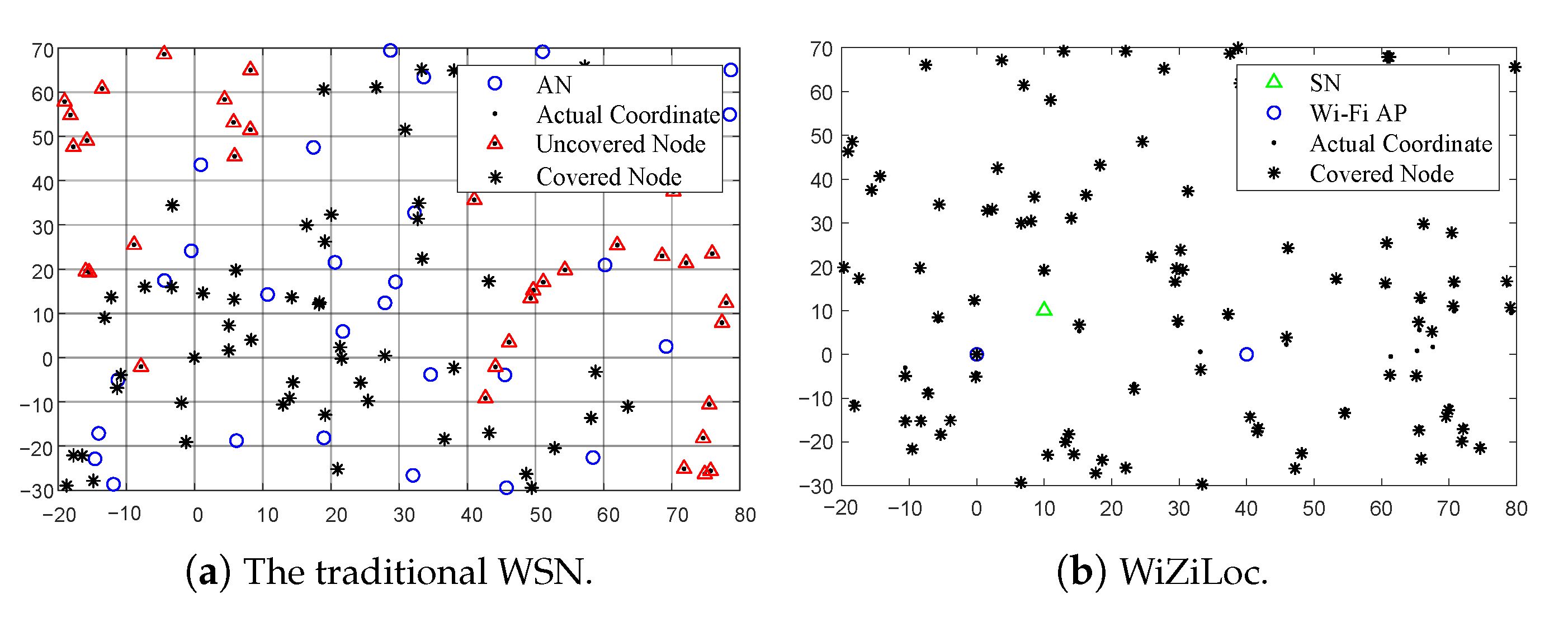
Limited by the coverage of ZNs, the conventional WSN needs a large number of ANs to enlarge the network coverage. In practical, the number of ANs cannot be unlimited, and evenly distributed in the monitoring area, thus a blind area will be appeared when positioning. The main contributions of WiZiLoc is to leverage the high-power Wi-Fi instead of the ANs to improve the network coverage. Hence, we investigate the coverage of WiZiLoc based on the simulations, as the simulation map with an area of 100 × 100 square meters illustrated in Figure 20. The x-axis is length and the y-axis is width. For comparison, we also depict the coverage of the traditional WSN. There are 30 ANs and 100 UZNs. It can be seen from the Figure 20a that even if arranged AN accounts for 30% of UZN, there are still a large number of dead corners causing node uncovered.
Compared with the WSN localization system, which requires a large number of ANs to achieve a certain coverage, WiZiLoc can achieve full coverage without any AN. As can be seen from Figure 20b where there are also 100 UZNs, WiZiLoc can achieve almost 100% coverage without deploying any AN in advance.
4.4. The Broadcasting Period
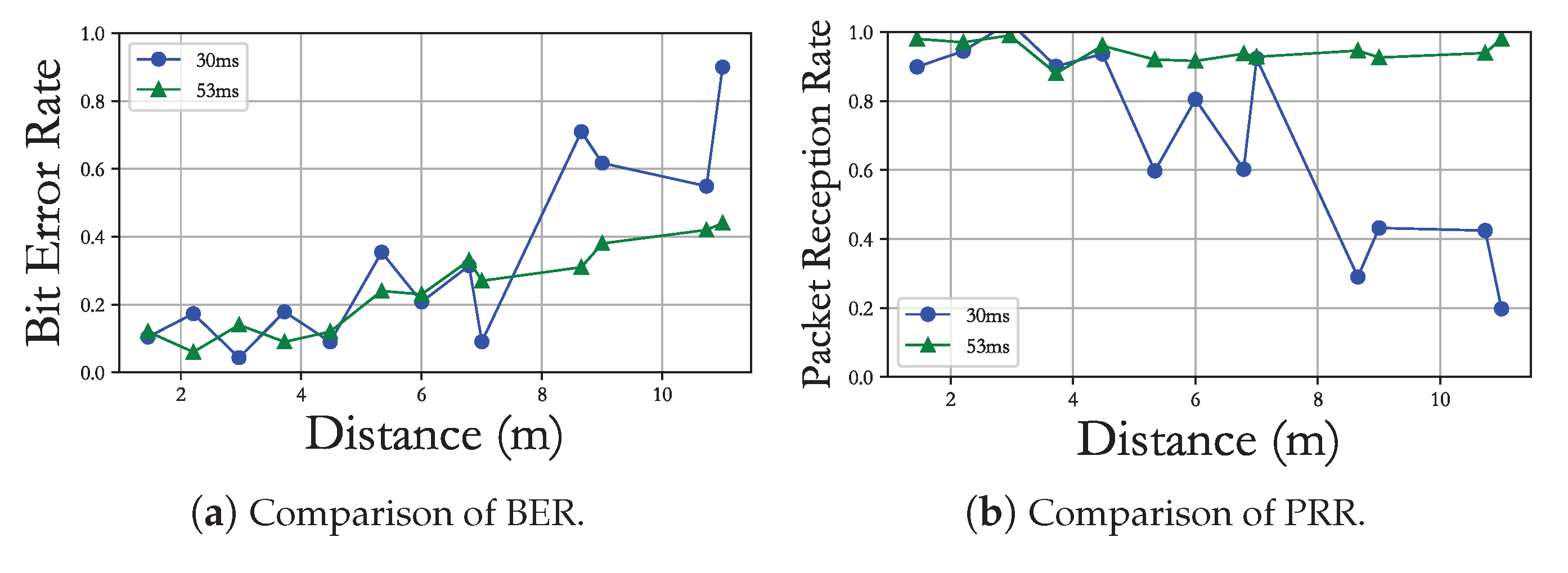
In order to reduce the impact of Wi-Fi interference on the communication among ZNs, we design a broadcasting period of Wi-Fi APs by choosing a prime number which is larger than the maximum wake-up period of ZNs. To verify the effectiveness of the design, we conduct experiments in the corridor under NLOS ambient environment. One USRP is deployed as the ZN sender with wake-up period 12 ms, and another USRP is placed beside to broadcast CTC packets with period 30 ms and 53 ms, respectively. A commodity CC2530 is used to be a ZigBee receiver.
Since there are multiple common divisors between 12 and 30, such as 2, 3, 4 and 6, according to our broadcast period analysis, this multiple common divisor situation will lead to relatively serious packet collisions, which will lead to poor communication performance (BER and PRR). For example, 53 is a prime number significantly larger than 12, so it is reasonable to get better communication performance. However, the broadcast period should not be too large, otherwise the throughput and system efficiency will be reduced. The experimental results are shown in Figure 21.
It can be seen from the Figure 21 that when the broadcasting period of CTC is the prime number 53 ms, the BER of ZNs is stable at 0.4 and the PPR is no less than 0.85. However, when the broadcasting period of CTC is 30 ms, the BER of ZNs degrades greatly when the distance beyond 7 m. By comparison, we find that the proposed prime number broadcasting period can improve the communication performance of ZNs in the network without affecting CTC packets reception.
4.5. Comparison
This paper compares WiZiLoc and the existing WSN localization system from four aspects: system structure, localization precision, system cost and algorithm complexity. The comparison results are shown in Table 1. Obviously, WiZiLoc outperforms the other methods in aspect of precision, cost and complexity.
5. Conclusions
In this paper, we propose WiZiLoc, an anchor-free, distributed localization system for WSN with decimeter accuracy. The main contribution of WiZiLoc is that no ANs are required. WiZiLoc leverage physical-level CTC to achieve localization in WSN system for the first time. To address the asymmetric coverage and Wi-Fi interference problems, a new progressive self-positioning method, ONION, is proposed. The CTC broadcasting period is designed to be the maximum prime number of the wake-up cycle of ZNs in the network. Extensive experiments and simulations have been performed on the prototype of WiZiLoc, the localization accuracy can be up to 0.6m, 0.8m in the presence of Wi-Fi interference and 1m in NLOS scenario. Experimental results show that the proposed WiZiLoc can achieve better performance than the conventional anchor-based WSN in terms of accuracy, robustness, coverage and cost, etc.
Because of the anchor-free characteristic, the cost of arranging anchor nodes in all kinds of traditional WSN application scenarios can be reduced (such as factory warehouse management, terminal container monitoring, etc.). CTC technology for localization is only a modest display of a master. If CTC is applied beyond positioning, such as real-time interaction, giving instructions and supervisory control, a greater vision can be achieved. However, the security of CTC communication needs attention. To resist illegal invasion, the information encryption and identity authentication of CTC need to be deliberated.
Author Contributions
Conceptualization, N.J. and B.Z.; methodology, B.Z.; software, B.Z.; validation, N.J. and L.W.; formal analysis, N.J. and B.Z.; investigation, B.Z.; resources, L.W.; data curation, B.Z.; writing—original draft preparation, B.Z.; writing—review and editing, N.J.; visualization, L.W.; supervision, N.J.; project administration, L.W.; funding acquisition, N.J. All authors have read and agreed to the published version of the manuscript.
Funding
This work was funded in part by the National Natural Science Foundation of China [Grant No. 61772453], the Natural Science Foundation of Hebei Province [Grant No. F2020203074, F2022203045].
Acknowledgments
Our grateful thanks go to the anonymous referees for detailed reviews and insightful comments that have helped to improve this article substantially. The funding’s support for our work is greatly appreciated.
Conflicts of Interest
The authors declare no conflict of interest.
References
- Shahraki, A.; Taherkordi, A.; Haugen, Ø.; Eliassen, F. A survey and future directions on clustering: From wsns to iot and modern networking paradigms. IEEE Trans. Netw. Serv. Manag. 2021, 18, 2242–2274. [Google Scholar] [CrossRef]
- Akyildiz, I.F.; Su, W.; Sankarasubramaniam, Y. Wireless sensor networks: A survey. Comput. Netw. 2002, 38, 393–422. [Google Scholar] [CrossRef] [Green Version]
- Souza, F.L.; Nakamura, E.F.; Pazzi, R.W. Target tracking for sensor networks: A survey. ACM Comput. Surv. 2016, 49, 1–31. [Google Scholar] [CrossRef] [Green Version]
- Annepu, V.; Rajesh, A.; Bagadi, B. Radial basis function-based node localization for unmanned aerial vehicle-assisted 5g wireless sensor networks. Neural Comput. Appl. 2021, 33, 12333–12346. [Google Scholar] [CrossRef]
- Yassin, A.; Nasser, Y.; Awad, M.; Al-Dubai, A.; Liu, R.; Yuen, C.; Raulefs, R.; Aboutanios, E. Recent advances in indoor localization: A survey on theoretical approaches and applications. IEEE Commun. Surv. Tutor. 2016, 19, 1327–1346. [Google Scholar] [CrossRef] [Green Version]
- He, W.; Cheng, R.; Mao, K.; Yan, K.; Wei, J.; Xu, Y. A novel anchorless node positioning method for wireless sensor network. J. Sens. 2022, 2022, 5385393. [Google Scholar] [CrossRef]
- Liu, W.; Luo, X.; Wei, G.; Liu, H. Node Localization Algorithm for Wireless Sensor Networks Based on Static Anchor Node Location Selection Strategy, Computer Communications. Available online: https://www.sciencedirect.com/science/article/pii/S0140366422002122 (accessed on 1 August 2022). [CrossRef]
- Huang, H.; Miao, W.; Min, G.; Huang, C.; Wang, C. Resilient range-based d-dimensional localization for mobile sensor networks. IEEE/ACM Trans. Netw. 2020, 28, 2037–2050. [Google Scholar] [CrossRef]
- Singh, S.P.; Sharma, S. Range free localization techniques in wireless sensor networks: A review. Procedia Comput. Sci. 2015, 57, 7–16. [Google Scholar] [CrossRef] [Green Version]
- Zhao, S.; Zhang, X.-P.; Cui, X.; Lu, M. A new toa localization and synchronization system with virtually synchronized periodic asymmetric ranging network. IEEE Internet Things J. 2021, 8, 9030–9044. [Google Scholar] [CrossRef]
- Sun, Y.; Zhang, F.; Wan, Q. Wireless sensor network-based localization method using tdoa measurements in mpr. IEEE Sens. J. 2019, 19, 3741–3750. [Google Scholar] [CrossRef]
- Liu, J.; Hu, M.; Zhou, M.; Ding, Z. Performance analysis and comparison for tdoa and dtdoa. In Proceedings of the 2021 3rd International Conference on Information Technology and Computer Communications, Shanghai, China, 23–25 April 2021; pp. 103–108. [Google Scholar]
- Vashistha, A.; Law, C.L. E-dtdoa based localization for wireless sensor networks with clock drift compensation. IEEE Sens. J. 2019, 20, 2648–2658. [Google Scholar] [CrossRef]
- Zheng, Y.; Sheng, M.; Liu, J.; Li, J. Exploiting aoa estimation accuracy for indoor localization: A weighted aoa-based approach. IEEE Wirel. Commun. Lett. 2019, 8, 65–68. [Google Scholar] [CrossRef]
- Sahota, H.; Kumar, R. Maximum-likelihood sensor node localization using received signal strength in multimedia with multipath characteristics. IEEE Syst. J. 2016, 6, 1–10. [Google Scholar] [CrossRef]
- Xie, Y.; Xiong, J.; Li, M.; Jamieson, K. md-track: Leveraging multi-dimensionality in passive indoor wi-fi tracking. In Proceedings of the 25th Annual International Conference, Athens, Greece, 15–18 May 2019; pp. 1–16. [Google Scholar]
- Costa, M.S.; Tomic, S.; Beko, M. An socp estimator for hybrid rss and aoa target localization in sensor networks. Sensors 2021, 21, 1731. [Google Scholar] [CrossRef]
- Panwar, K.; Katwe, M.; Babu, P.; Ghare, P.; Singh, K. A majorization-minimization algorithm for hybrid toa-rss based localization in nlos environment. IEEE Commun. Lett. 2022, 26, 1017–1021. [Google Scholar] [CrossRef]
- Panwar, K.; Fatima, G.; Babu, P. Optimal sensor placement for hybrid source localization using fused toa-rss-aoa measurements. arXiv 2022, arXiv:2204.06198. [Google Scholar] [CrossRef]
- Panwar, K.; Babu, P. Majorization-minimization based hybrid localization method for high precision localization in wireless sensor networks. arXiv 2022, arXiv:2205.03881. [Google Scholar]
- Hosseinianfar, H.; Brandt-Pearce, M. Performance limits for fingerprinting-based indoor optical communication positioning systems exploiting multipath reflections. IEEE Photonics J. 2020, 12, 1–16. [Google Scholar] [CrossRef]
- Kaur, A.; Kumar, P.; Gupta, G.P. A weighted centroid localization algorithm for randomly deployed wireless sensor networks. J. King Saud Univ. Comput. Inf. Sci. 2019, 31, 82–91. [Google Scholar] [CrossRef]
- Chen, T.; Hou, S.; Sun, L. An enhanced dv-hop positioning scheme based on spring model and reliable beacon node set. Comput. Netw. 2022, 209, 108926. [Google Scholar] [CrossRef]
- Shen, S.; Yang, B.; Qian, K.; Wang, W.; Jiang, X.; She, Y.; Wang, Y. An improved amorphous localization algorithm for wireless sensor networks. In Proceedings of the 2016 International Conference on Networking and Network Applications (NaNA), Hokkaido, Japan, 23–25 July 2016; pp. 69–72. [Google Scholar] [CrossRef]
- Liu, J.; Wang, Z.; Yao, M.; Qiu, Z. Vn-apit: Virtual nodes-based range-free apit localization scheme for wsn. Wirel. Netw. 2016, 22, 867–878. [Google Scholar] [CrossRef]
- Saeed, N.; Nam, H.; Al-Naffouri, T.Y.; Alouini, M.S. A state-of-the-art survey on multidimensional scaling-based localization techniques. IEEE Commun. Surv. Tutor. 2020, 21, 3565–3583. [Google Scholar] [CrossRef] [Green Version]
- Zhang, S.; Liu, X.; Wang, J.; Cao, J.; Min, G. Accurate range-free localization for anisotropic wireless sensor networks. ACM Trans. Sens. Netw. 2015, 11, 1–28. [Google Scholar] [CrossRef]
- Savarese, C.; Rabaey, J.M.; Beutel, J. Location in distributed ad-hoc wireless sensor networks. In Proceedings of the 2001 IEEE International Conference on Acoustics, Speech, and Signal Processing (Cat. No. 01CH37221), Salt Lake City, UT, USA, 7–11 May 2001; Volume 4, pp. 2037–2040. [Google Scholar]
- Priyantha, N.B.; Balakrishnan, H.; Demaine, E.; Teller, S. Anchor-free distributed localization in sensor networks. In Proceedings of the 1st International Conference on Embedded Networked Sensor Systems, Los Angeles, CA, USA, 5–7 November 2003; pp. 340–341. [Google Scholar]
- Shang, Y.; Ruml, W.; Zhang, Y.; Fromherz, M.P.J. Localization from mere connectivity. In Proceedings of the 4th ACM International Symposium on Mobile Ad Hoc Networking and Computing, Annapolis, MD, USA, 1–3 June 2003; pp. 201–212. [Google Scholar]
- Benbadis, F.; Friedman, T.; De Amorim, M.D.; Fdida, S. Gps-free-free positioning system for wireless sensor networks. In Proceedings of the Second IFIP International Conference on Wireless and Optical Communications Networks, Dubai, United Arab Emirates, 6–8 March 2005; pp. 541–545. [Google Scholar]
- Qu, H.; Wicker, S.B. Anchor-free localization in rapidly-deployed wireless sensor networks. In Proceedings of the 2006 IEEE International Conference on Mobile Ad Hoc and Sensor Systems, Vancouver, BC, Canada, 9–12 October 2006; pp. 627–632. [Google Scholar]
- Fang, L.; Du, W.; Ning, P. A beacon-less location discovery scheme for wireless sensor networks. In Proceedings of the IEEE 24th Annual Joint Conference of the IEEE Computer and Communications Societies, Miami, FL, USA, 13–17 March 2005; pp. 161–171. [Google Scholar]
- Fuiorea, D.; Gui, V.; Pescaru, D.; Toma, C. Using registration algorithms for wireless sensor network node localization. In Proceedings of the 2007 4th International Symposium on Applied Computational Intelligence and Informatics, Timisoara, Romania, 17–18 May 2007; pp. 209–214. [Google Scholar]
- He, Y.; Guo, X.; Zheng, X.; Yu, Z.; Zhang, J.; Jiang, H.; Na, X.; Zhang, J. Cross-technology communication for the internet of things: A survey. ACM Comput. Surv. 2023, 55, 1–29. [Google Scholar] [CrossRef]
- Li, Z.; Tian, H. Webee: Physical-layer cross-technology communication via emulation. In Proceedings of the 23rd Annual International Conference, Staten Island, NY, USA, 7–9 June 2017; pp. 2–14. [Google Scholar]
- He, Y.; Guo, X.; Zhang, J.; Jiang, H. Wide: Physical-level ctc via digital emulation. IEEE/ACM Trans. Netw. 2021, 29, 1567–1579. [Google Scholar] [CrossRef]
- Xia, D.; Zheng, X.; Liu, L.; Wang, C.; Ma, H. c-chirp: Towards symmetric cross-technology communication over asymmetric channels. IEEE/ACM Trans. Netw. 2021, 29, 1169–1182. [Google Scholar] [CrossRef]
- Zheng, X.; Xia, D.; Guo, X.; Liu, L.; Ma, H. Portal: Transparent cross-technology opportunistic forwarding for low-power wireless networks. In Proceedings of the Mobihoc’20: The Twenty-first ACM International Symposium on Theory, Algorithmic Foundations, and Protocol Design for Mobile Networks and Mobile Computing, , Boston, MA, USA, 11–14 October 2020; pp. 241–250. [Google Scholar]
- Jing, N.; Zhang, B.; Liu, G.; Yang, L.; Wang, L. Anchor-Free Self-Positioning in Wireless Sensor Networks via Cross-Technology Communication. In Proceedings of the 2021 IEEE 27th International Conference on Parallel and Distributed Systems (ICPADS), Beijing, China, 14–16 December 2021; pp. 915–922. [Google Scholar]
- Kristalina, P.; Pratiarso, A.; Badriyah, T.; Putro, E.D. A wireless sensor networks localization using geometric triangulation scheme for object tracking in urban search and rescue application. In Proceedings of the 2016 2nd International Conference on Science in Information Technology (ICSITech), Yogyakarta, Indonesia, 27–28 October 2016; pp. 254–259. [Google Scholar]
- Dutta, S.; Obaidat, M.S.; Dahal, K.; Giri, D.; Neogy, S. M-memhs: Modified minimization of error in multihop system for localization of unknown sensor nodes. IEEE Syst. J. 2019, 13, 215–225. [Google Scholar] [CrossRef] [Green Version]
- Kumar, A. Karampal, Optimized range-free 3d node localization in wireless sensor networks using firefly algorithm. In Proceedings of the 2015 International Conference on Signal Processing and Communication (ICSC), Singapore, 25–27 February 2015; pp. 14–19. [Google Scholar] [CrossRef]
Figure 1.
The architecture of WEBee.

Figure 2.
WiZiLoc overview.

Figure 3.
Technical challenges of WiZiLoc.

Figure 4.
Performance of ZigBee and CTC in presence of interference.

Figure 5.
Workflow of WiZiLoc.

Figure 6.
Basic idea of ONION.

Figure 7.
Inherent errors of ONION.

Figure 8.
Cause of the error near x-axis.

Figure 9.
CDF of actual scene localization error.

Figure 10.
Cause of the error in the random area around the x-axis.

Figure 11.
Enhanced ONION after modifications.

Figure 12.
Time coordinate axis model.

Figure 13.
Example that ZNs cannot receive CTC packets.

Figure 14.
Example with prime number design.

Figure 15.
Schematic diagram of the environment.

Figure 16.
Performance with interference.

Figure 17.
Density vs. accuracy.

Figure 18.
LOS vs. NLOS.

Figure 19.
Location errors in canteen and laboratory corridor.

Figure 20.
Coverage comparison of WSN and WiZiLoc.

Figure 21.
Performance with different broadcasting period.


Publisher’s Note: MDPI stays neutral with regard to jurisdictional claims in published maps and institutional affiliations. |
© 2022 by the authors. Licensee MDPI, Basel, Switzerland. This article is an open access article distributed under the terms and conditions of the Creative Commons Attribution (CC BY) license (https://creativecommons.org/licenses/by/4.0/).
Share and Cite
MDPI and ACS Style
Jing, N.; Zhang, B.; Wang, L. A Novel Anchor-Free Localization Method Using Cross-Technology Communication for Wireless Sensor Network. Electronics 2022, 11, 4025. https://doi.org/10.3390/electronics11234025
AMA Style
Jing N, Zhang B, Wang L. A Novel Anchor-Free Localization Method Using Cross-Technology Communication for Wireless Sensor Network. Electronics. 2022; 11(23):4025. https://doi.org/10.3390/electronics11234025
Chicago/Turabian StyleJing, Nan, Bowen Zhang, and Lin Wang. 2022. "A Novel Anchor-Free Localization Method Using Cross-Technology Communication for Wireless Sensor Network" Electronics 11, no. 23: 4025. https://doi.org/10.3390/electronics11234025
Note that from the first issue of 2016, this journal uses article numbers instead of page numbers. See further details here.