
AIoT Precision Feeding Management System


1
Department of Engineering Science, National Cheng Kung University, Tainan 701401, Taiwan
2
Department of Telecommunication Engineering, National Kaohsiung University of Science and Technology, Kaohsiung 811213, Taiwan
*
Author to whom correspondence should be addressed.
Electronics 2022, 11(20), 3358; https://doi.org/10.3390/electronics11203358
Submission received: 29 August 2022
/
Revised: 9 October 2022
/
Accepted: 10 October 2022
/
Published: 18 October 2022
(This article belongs to the Topic Artificial Intelligence in Sensors)
Abstract
:Different fish species and different growth stages require different amounts of fish pellets. Excessive fish pellets increase the cost of aquaculture, and the leftover fish pellets sink to the bottom of the fish farm. This causes water pollution in the fish farm. Weather changes and providing too many or too little fish pellets affect the growth of the fish. In light of the abovementioned factors, this article uses the artificial intelligence of things (AIoT) precision feeding management system to improve an existing fish feeder. The AIoT precision feeding management system is placed on the water surface of the breeding pond to measure the water surface fluctuations in the area of fish pellet application. The buoy, with s built-in three-axis accelerometer, senses the water surface fluctuations when the fish are foraging. Then, through the wireless transmission module, the data are sent back to the receiver and control device of the fish feeder. When the fish feeder receives the signal, it judges the returned value to adjust the feeding time. Through this system, the intelligent feeding of fish can be achieved by adjusting the amount of fish pellets in order to reduce the cost of aquaculture.
1. Introduction
At present, different automatic fish feeders are in use, and they mainly be divided into three types: automatic fish feeders for fish farms on large ponds, cage culture, and industrial fish farms [1,2,3].
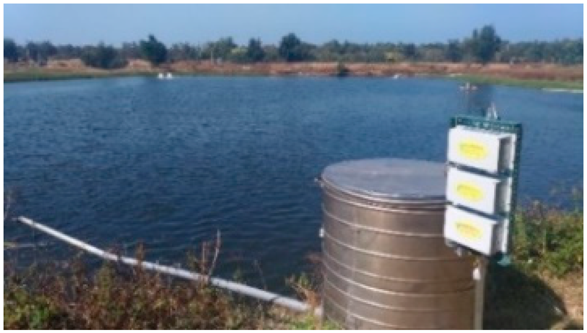
1.1. Automatic Fish Feeders for Fish Farms on Large Ponds
This automatic fish feeder has a general throwing area of 10–50 square meters, while the motor power is 30–100 watts and the throwing distance is 2–18 m, as shown in Figure 1. The volume of the feeding box can hold 60–120 kg of fish pellets, and the area that can be fed evenly by each unit is 5–15 mu. This type of automatic fish feeder is currently the most frequently used among fish farmers.
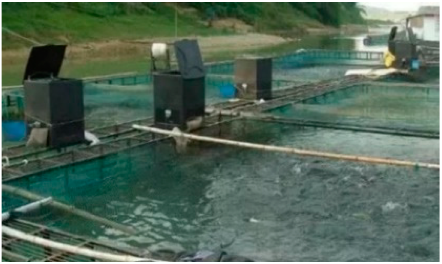
1.2. Automatic Fish Feeders for Cage Culture
According to the different conditions of the cages, they can be divided into deep-water cage fish feeders and water surface cage fish feeders, as shown in Figure 2. The deep-water cage fish feeder directly transports the fish pellets to the center of the cage at a depth of 1–2 m from the water surface. The water surface cage fish feeder throws the fish pellets onto the water surface in the center of the 25-square-meter cages, and the throwing area is 2.8–3.2 square meters.
1.3. Automatic Fish Feeders for Industrial Fish Farms
This fish feeder is commonly used in greenhouse fish farms and industrial fish farms, as shown in Figure 3. The amount of fish pellets thrown by the fish feeder each time is not great, but it is very uniform. Generally, the throwing area is 0.8–1.2 square meters.
In the study reported in this article, it was found that the automatic fish feeder used in aquaculture feeds fish using a time-controlled method. However, the types of fish and the growth stages of the fish are different, and the amounts of fish pellets they eat are also be different. If the fish pellets are added in quantities too great, it will affect the water quality of the breeding pond and then deteriorate the growing environment of the fish [4]. This will cause the fish farmer to lose fingerlings and cause a substantial increase in costs [5]. Although there are automatic feeding products on the market, they are all automatically timed, quantitative and immovable fish feeders. They cannot spread the fish pellets evenly over the entire breeding pond [6]. Although it is possible to install several fish feeders around the pond to increase the feed range, this method increases the labor costs when replenishing the fish pellets [7]. Another method is to centrally control a single feed bucket and use automated equipment to deliver fish pellets over a long distance and a wide range. However, the feed delivery method and the uniformity of the feed spraying are still problems to be overcome [8]. In addition, the abovementioned method still has two main disadvantages. Firstly, as far as the actual breeding site is concerned, the aisle around the pond usually adopts the form of a single walking space, allowing one member of staff at most to enter and exit with a small cart. Therefore, there may not be enough space to install a fish feeder system or a large fish feeder. If the equipment is designed to be suspended above the pond, the actual cost may be too high.
The second disadvantage is that, if an automated system is used, additional machinery and lines must be set up for each pond, resulting in lower convenience and high installation costs. The abovementioned traditional feeding methods all involve feeding in large quantities, which leads to the overcrowding of aquatic products [9]. The leftover fish pellets that are not eaten in time pollute the water, which leads to the outbreak of aquatic infectious diseases [10]. To solve the problem of fish feeding in high densities or traditional aquaculture, our method uses a three-axis accelerometer to measure the water surface fluctuations. When the feeding starts, the fish pellets are placed near the artificial intelligence of things (AIoT) precision feeding management system to detect the water surface fluctuations when the fish are rushing for food. When the hunger of the fish gradually decreases, the level of competition for food will also decrease, so that the water surface fluctuations will be reduced. This allows us to control the fish feeder so as to reduce the deterioration of the water quality and the cost of fish pellets [11]. In this article, the motor torque controller is accounted for in order to develop a more intelligent feeding method for the AIoT precision feeding management system, which can control the feed amount.
2. Motivation
According to the statistics of the Fisheries Agency, Council of Agriculture, Executive Yuan, although the production of aquaculture in Taiwan is smaller than that of deep-sea fishing, this production still accounts for 25% of the total production and increases year by year [12]. It can be seen that the economy of aquaculture has an important position. In recent years, intelligent aquaculture has gradually risen in importance. However, in terms of the improvement of the feeding strategies, only the simple timing-control feeding can replace the artificial feeding method used at present. An insufficient fish pellet input leads to malnutrition, while excessive fish pellets can result in wasted costs and contaminate the water in the fish farm. The purpose of this article is to solve the problems of insufficient or excessive, wasted fish pellets in aquaculture. In addition to the difference in the amount of fish pellets eaten due to the growth of the fish, changes in the weather or water temperature also affect the appetite of the fish. Therefore, it is more important to consider how to design a set of AIoT precision feeding management systems that can effectively and intelligently control the length of the feeding time [13].
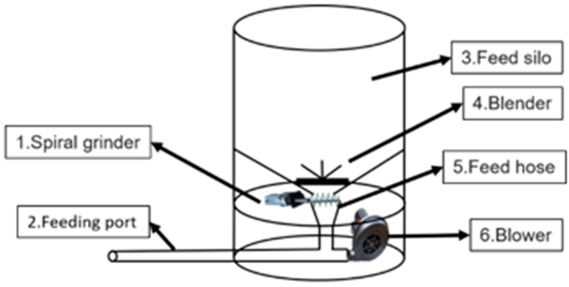
Figure 4 shows a diagram of the commercially available fish feeder. The fish pellets fall from the feed silo through the copper opening. Then, the small motor of the grinder pushes the spiral grinding rod to release the grinded fish pellets into the blower port. In addition, the copper opening can be fine-tuned through the adjustment rod of the grinder in order to achieve the purpose of controlling the rate of baiting. The fish pellets are stored in the feed silo, and then the fish pellets are blown out by the blower after the fish pellets are dropped through the abovementioned mechanism.
In fact, the spiral grinding rod of the automatic fish feeder cannot prevent the fish pellets from falling. It can only stop the feeding action by stopping the blower from blowing out the fish pellets or closing the bottom opening under the stirring rod in order to stop the feeding. In addition, the volume of air blown out by the blower can be fully opened. If one wants to achieve the results gained by controlling the feeding location, one must be able to control the air volume. We will discuss the two abovementioned points.
3. System Design
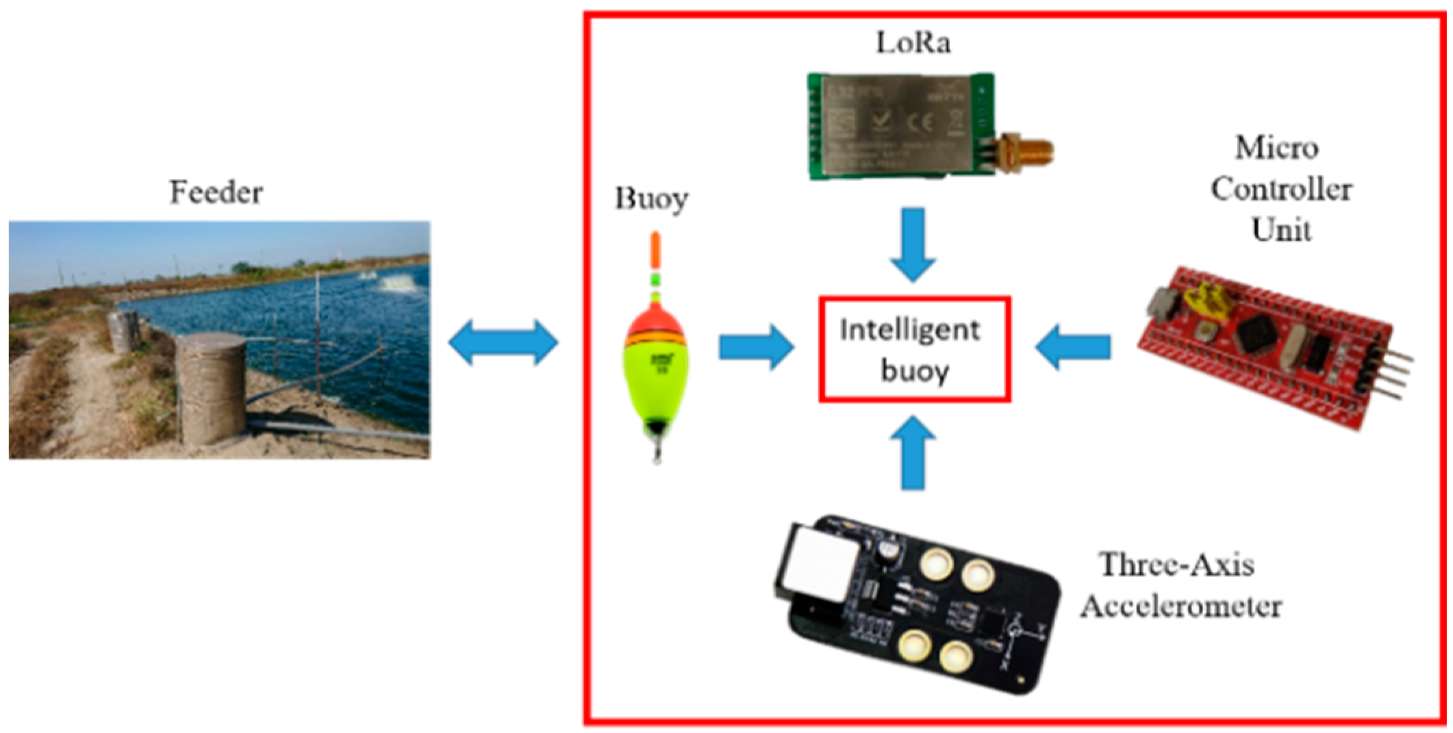
In the process of surveying the fish farms, the breeders know that the fish have the habit of competing for food when feeding. As shown in Figure 5, the fish will concentrate in the spraying area and grab the fish pellets, which will cause the water surface to fluctuate violently. The three-axis accelerometer is suitable for measuring the water surface fluctuations. Therefore, our method uses the buoy’s built-in, three-axis accelerometer and wireless transmission module to establish the spraying area of the fish feeder in order to sense the water surface fluctuations caused by the competition for food. We then compare these with the water surface fluctuations when the fish are full so as to judge the change in the water surface fluctuations. The data are then sent back to the receiver in the fish feeder on the shore through the wireless transmission module. The system is mainly composed of an intelligent fish feeder and a customized buoy system, as shown in Figure 6. When the scheduled feeding time is reached, the AIoT precision feeding management system will start the fish feeder and send a signal to the buoy system for analysis. If the water surface fluctuations are small, the fish feeder will reduce the voltage of its internal grinder motor. This will cause the fish pellets to be crushed more slowly, which in turn reduces the amount of fish pellets being sprayed. If the water surface fluctuations tend to be stable, the fish feeder will stop spraying and wait for the next feeding session.
3.1. Customized Buoy System
At present, the fish feeder used in aquaculture is to set the time for feeding. Although it can solve the problem of personnel cost, it cannot control the increase or decrease in the amount of fish pellets as the fish grow and the water temperature changes. The fish have the habit of competing for food during the feeding process, and this habit affects the water surface fluctuations [14,15]. Therefore, a three-axis accelerometer is added to the buoy. We can use the X, Y, and Z axes of the three-axis accelerometer to sense the water surface fluctuations during the feeding. According to the data detected by the three-axis accelerometer and wireless transmission technology, the system adjusts the action of the fish feeder and decides to extend the feeding time or to end it early.
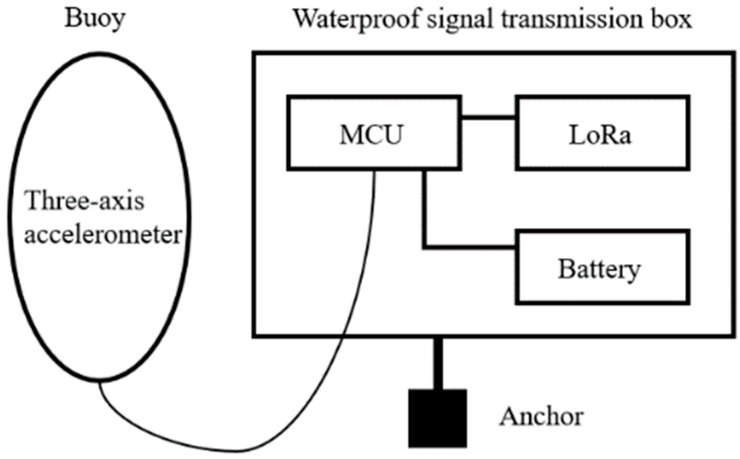
A three-axis accelerometer is placed in the customized buoy, which is used to sense the water surface fluctuations caused by the competition for food [16,17]. Information is transmitted to the waterproof signal transmission box through inter-integrated circuit, and the value is returned by the three-axis accelerometer, integrated with a single low-cost chip. Then, the data are sent back to the shore through the wireless transmission module. The architecture of the custom buoy and controller is shown in Figure 7. The system uses a waterproof box to prevent water from entering the electronic components and transmission modules inside. The bottom of the waterproof box is anchored to prevent the AIoT precision feeding management system from being pushed away from the sensing area due to strong winds or excessive competition for food.
3.2. Three-Axis Accelerometer
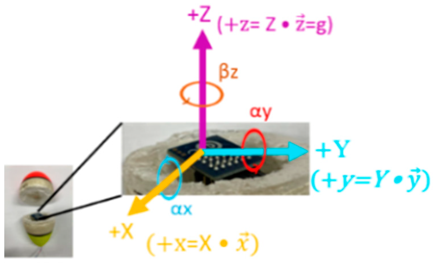
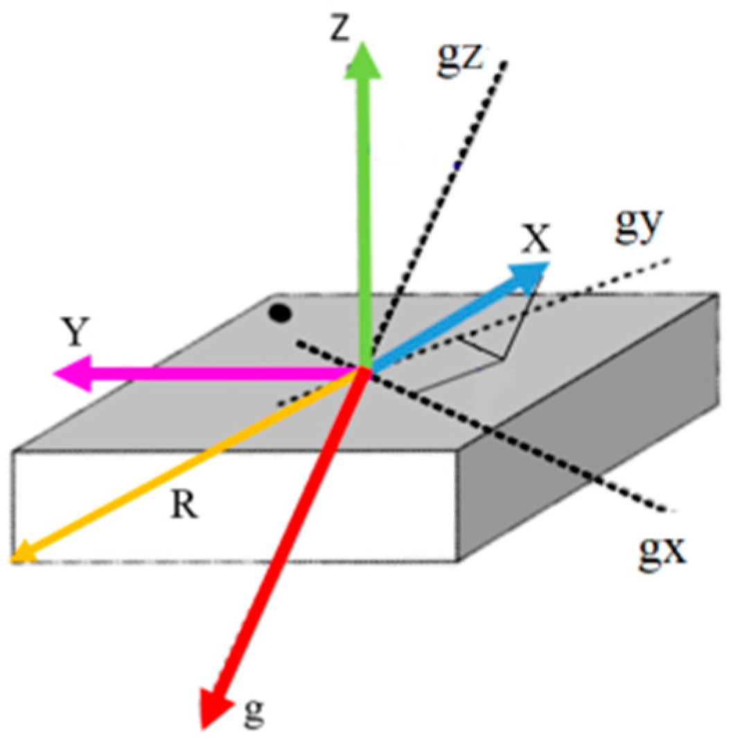
The measurement method records the response and the rotation angle of the three-axis accelerometer. The device under test (DUT) is separately rotated in the direction of the +X, +Y, and +Z. The planes of rotation perpendicular to the three orthogonal axes are αx, αy, and βz, as shown in Figure 8. Yellow, blue, and purple arrows represent the orthogonal unit vectors +x, +y, and +z in the stationary position, which is defined as the dot product of the unit vectors (+X, +Y, +Z) in the stationary position and the variation in the vectors (, , ) [18].
3.3. Wireless Transmission Module
The low-power wide-area network (LPWAN) is a high-performance communication technology that enables a low power consumption and long distances. In this study, cellular networks were used to replace existing communication architectures. Examples are Bluetooth, Wi-Fi, NB-IoT, Sigfox, and LoRaWAN. Table 1 is the data table of each transmission module. These wireless transmission techniques are common methods used for reading and controlling sensors. The transceiver that covers the two-way communication is useful for data collection and transmission packets. In addition, these transceivers have interesting features that can be used to build protocol elements, in contrast to the traditional transceivers used in IoT networks. We selected the 4G communication module to transmit data to the server. LoRa was used as a communication system for the data transfer between the buoy system and AIoT precision feeding management system [19,20].
Recent decades have witnessed the rapid development of mobile communication technology. The development of the wireless broadband technologies is a response to the growing demand for mobile internet and wireless multimedia applications. Mobile communications play an important role in the telecommunication industry. Both LTE and WiMAX use the highly efficient orthogonal frequency division multiple access (OFDMA) technology architecture for downloading; thus, the download speeds of both are roughly the same. However, the upload speeds of the two are not the same. WiMAX upload adopts the OFDMA architecture, but LTE adopts the single carrier frequency division multiple access (SC-FDMA) technology architecture. The two technologies are integrated into the network architecture described in this article. In 4G mobile communication technology, high mobility is guaranteed by high levels of data rates and applications.
3.4. Optocoupler AC Voltage Controller
A voltage controller is an electronic module mounted on a thyristor, SCR, TRIAC, or IGBT. It can convert the input of a fixed frequency, or fixed voltage alternating current (AC), to acquire the variable voltage in the output provided to a resistive load. Such variable voltage outputs are used to dim streetlamps, change industrial heating levels and the speed of winding machines, and many other applications. It is possible to sense the zero-voltage crossing of AC voltage by rectifying it with a full-wave rectifier. Then, we can use an optocoupler that turns off and on at zero-voltage crossings and past zero-voltage crossings [21].
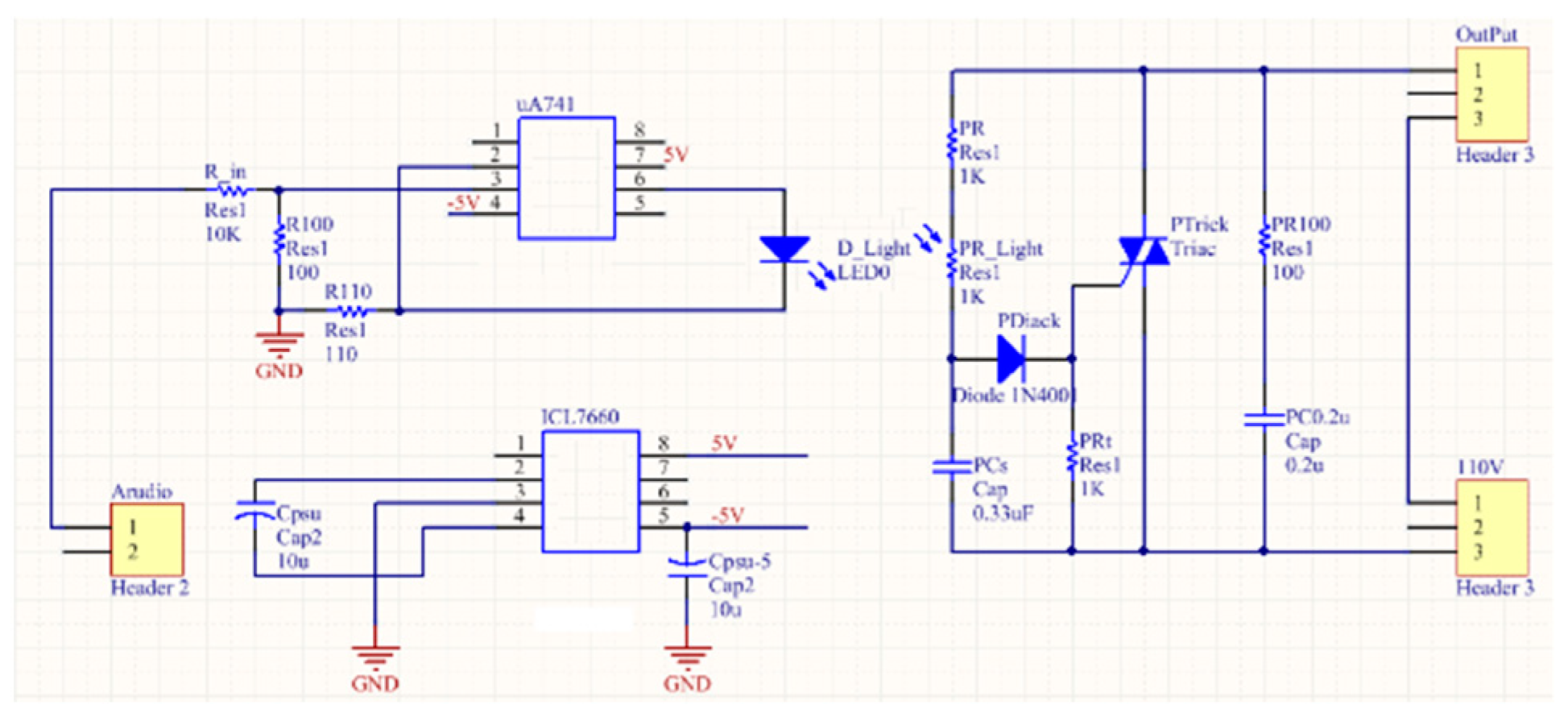
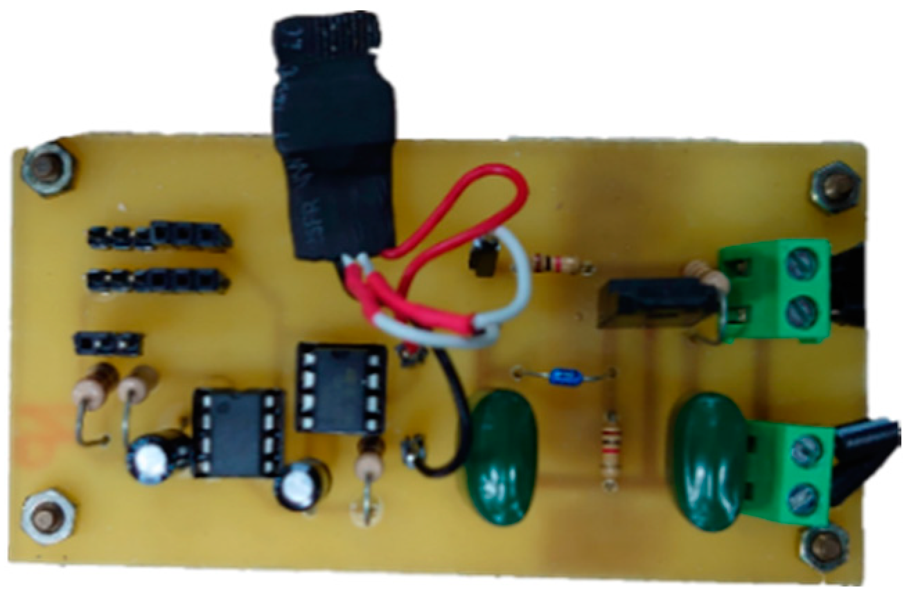
This system is an optocoupler voltage controller parallel-connected AC busbar system [22,23] using the DC 5 V PWM signal to control the 110 V AC system. here, a new control method for controlling the voltage is proposed. The control law is to sense the ratio of the input voltage to the output voltage and use the two sensed loops to correct the input current after the calculation. The input voltage can change the power according to the output ratio. The main purpose is automatic operation in the open and closed circuit, which means switching the circuit state to a high speed to reduce the AC voltage. This can reduce the total current harmonic distortion rate and improve the power factor. Figure 9 shows the optocoupler AC voltage controller circuit designed for this system, in which an µA741 is used as the stable input voltage. Since the µA741 requires positive and negative 5 volts DC, an ICL7660 is used to convert the positive 5 volts to negative 5 volts. Figure 10 depicts the actual circuit board. The part on the left shows the 5 V power input and the 5 V PWM control signal input. The part on the right shows the AC 110 V input and the AC voltage output after the voltage modulation.
3.5. Design of the Intelligent Fish Feeder
The system is designed to control the feeding time and fish pellet application. During the feeding process, the system judges whether the fish are full according to the received data. If the fish are still active, the fish feeder will not slow down. If the received data indicate that the fish’s action has gradually eased, the single-chip control optocoupler controller will be activated. In this way, the speed of the grinder inside the fish feeder is reduced to slow down the rate of spraying of the fish pellets. If the feeding upper limit time is reached, the control system will stop the action of the fish feeder.
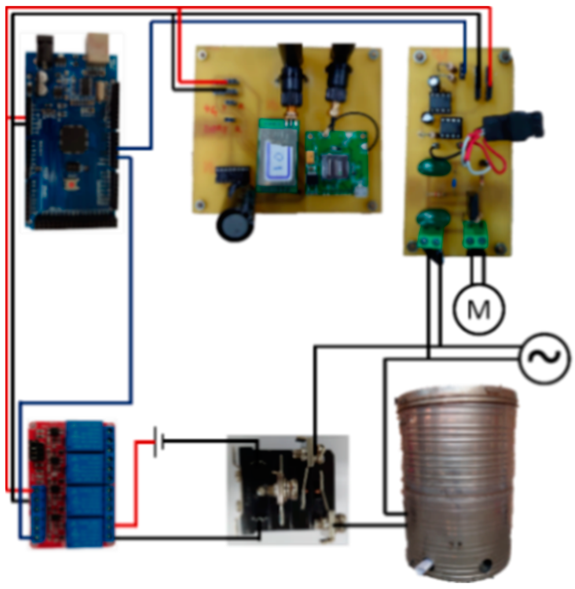
The current of the blower inside the fish feeder is great. Thus, the system uses a relay that can withstand a large current as the switch circuit of the blower. Since the relay needs a larger voltage in order to function than the general relay, this system connects the general relay through series in the front end of the relay to increase the voltage. At the same time, it can protect the single chip from being damaged by the counter EMF of the coil in the relay [24]. Figure 11 depicts the controller architecture of the fish feeder used for this system.
3.6. The Flow of the Fish Feeder Control System
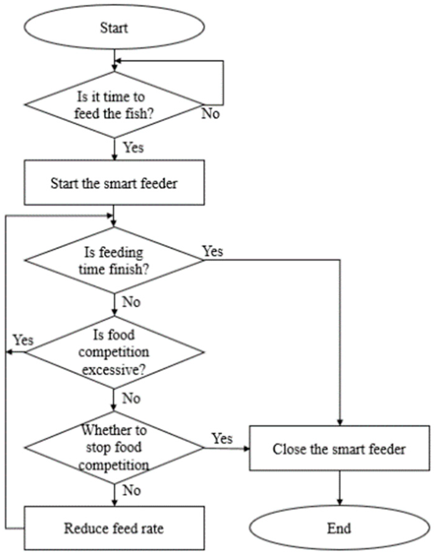
The control circuit in the fish feeder, which is placed on the shore, is used as the main control terminal, and the buoys placed in each fish farm are the signal terminals. This system uses a single chip to process the control of the fish feeder connected to each fish farm. The signals sent by the intelligent buoy are processed through the program, as shown in Figure 12. When the system starts to automatically produce fish pellets, the fish feeder will start to calculate the speed of the automatic feeding and will start to measure the feeding time. If the time reaches the preset maximum feeding time, the fish feeder will stop. If the maximum feeding time is not reached, the fish feeder will continue to run. About every 10 s, the fish feeder will send a signal to the AIoT precision feeding management system for measurement and then send the data back to the fish feeder for data analysis. If the level of competition for food has not slowed down, the fish feeder will continue to add fish pellets and continue to detect whether the maximum time for feeding has been reached. If the level of competition for food has slowed down, the system will determine whether the fish have stopped competing for food. If the fish have stopped competing for food, the fish feeder is turned off.
3.7. The Algorithm of the Three-Axis Accelerometer
To realize the implementation of the intelligent buoy system, we calculated the acceleration state of the three-axis accelerometer when it was horizontally stationary. The gravity component of the Z axis is the gravitational acceleration, while the gravity components of X and Y axes are 0 g. If there is an angle with a horizontal line, an acceleration vector will be generated, the vector of which is evaluated using the product rule [25].
3.7.1. When the X axis acceleration is gx, the angle between the horizontal line and the X-axis is . The angle with the gravitational acceleration is .
3.7.2. When the Y axis acceleration is gy, the angle between the horizontal line and the Y-axis is . The angle with the gravitational acceleration is .
3.7.3. When the Z axis acceleration is gz, the angle between the horizontal line and the Z-axis is . The angle with the gravitational acceleration is .
Therefore, the components of the gravitational acceleration in the directions of each axis are:
The gravitational acceleration and components form a right triangle, as shown in Figure 13. The third side of the right triangle is formed by the gravitational acceleration, and the component gx is . The third side of the right triangle is formed by the gravitational acceleration, and the component gy is . The third side of the right triangle is formed by the gravitational acceleration, and the component gz is . According to the Pythagorean theorem, this can be expressed as:
Therefore,
From (1) and (7), we get (10). From (2) and (8), we get (11). From (3) and (9), we get (12):
Therefore, when using the three-axis accelerometer to measure the acceleration values gx, gy, and gz on the three axes, the values of x1, y1, and z1 can be calculated through the inverse trigonometric function. We can use the average values of Δx, Δy, and Δz to find the intensity of the competition for food.
4. Presentation
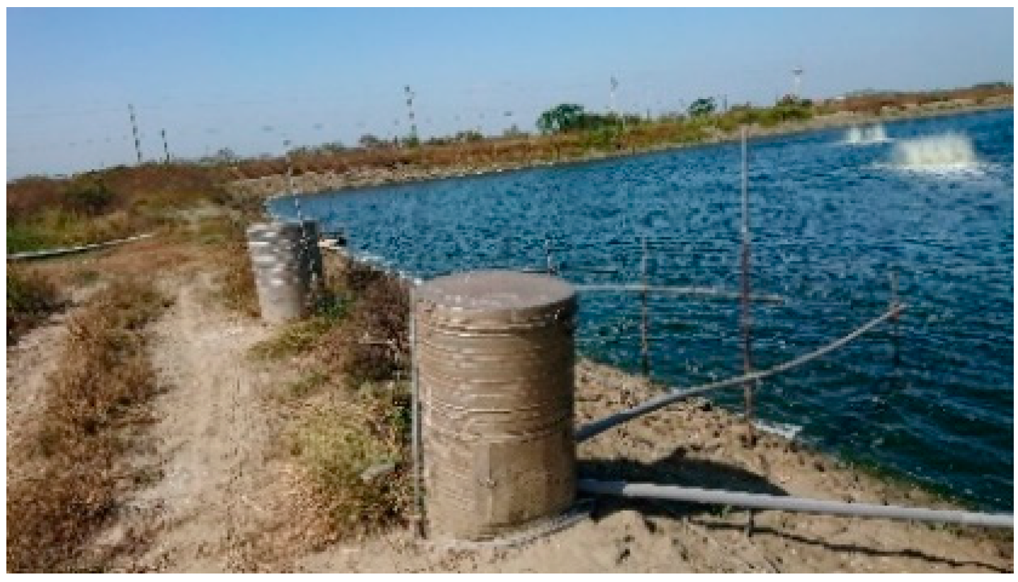
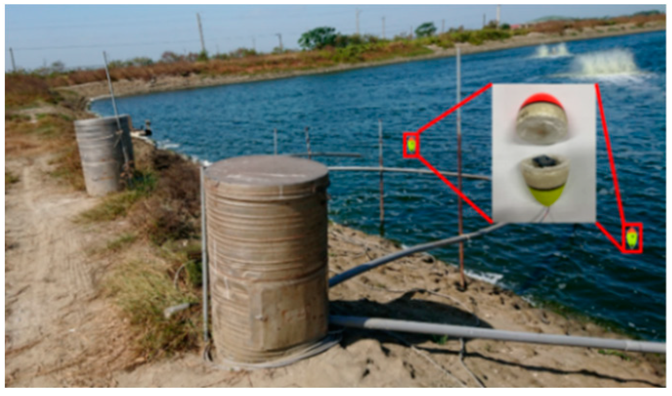
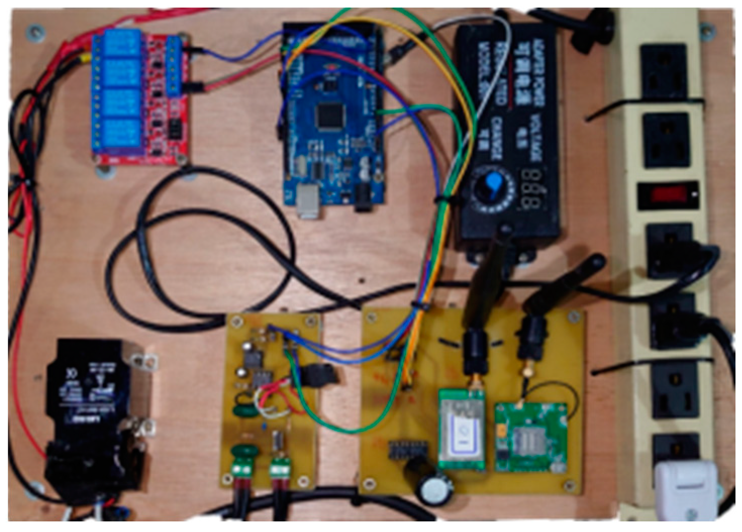
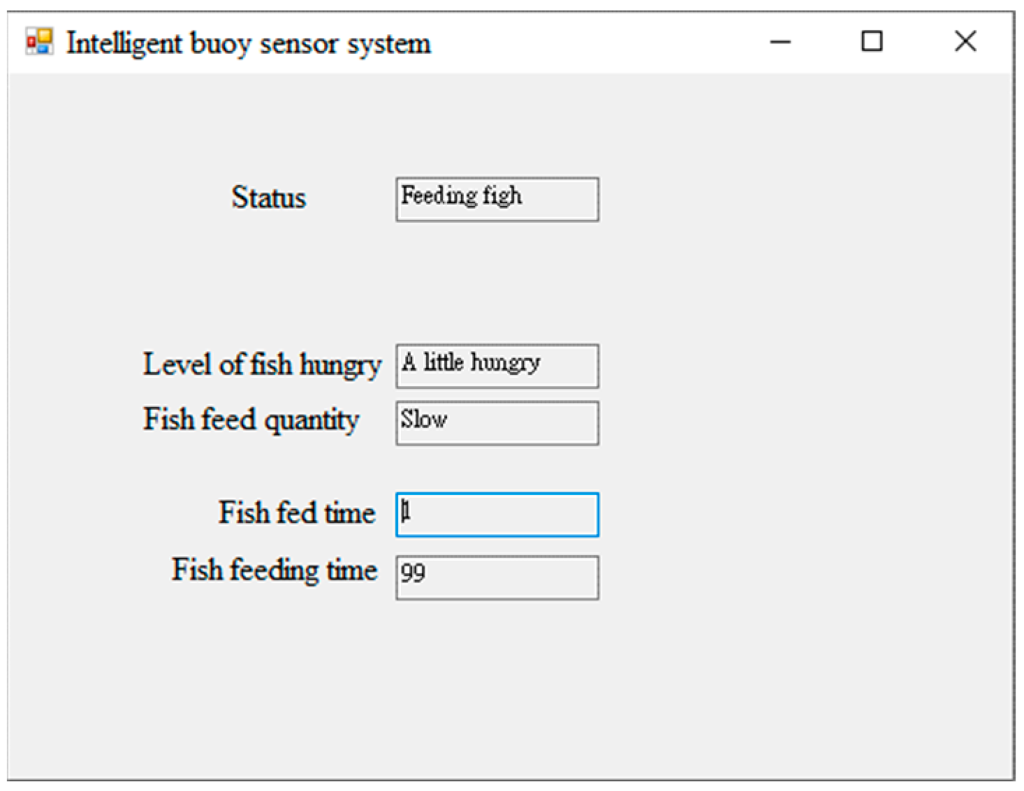
The purpose of this article is to propose an AIoT precision feeding management system to improve on the existing automatic feeding system on the market. It can achieve the effect of reducing the costs of labor and fish pellets [26,27]. Moreover, the AIoT precision feeding management system also has the advantage of being easy to install, allowing the fish farmer to easily replace or move the equipment. This system can help the fish farmer to fully achieve intelligent feeding and use the sensing circuit to remind the feed silo of insufficient fish pellets. The AIoT precision feeding management system is placed in the spraying area in order to measure the intensity of the water surface fluctuations when the competition for food starts, as shown in Figure 14. The LoRa is used to transmit data to the control circuit of the fish feeder, as shown in Figure 15. Through the control circuit of the fish feeder, the system can judge the degree of competition for food and control the switch of the fish feeder to adjust the speed of feeding. The state of the AIoT precision feeding management system, the intensity of the fish pellet spraying, the fish feeding time, and the maximum amount of time remaining for feeding can also be monitored by the computer, as shown in Figure 16 [28,29].
5. Conclusions
Table 2 shows a comparison between the AIoT precision feeding management system and other similar products on the market. In this study, a self-designed intelligent buoy with a three-axis accelerometer was used to detect the water surface fluctuations caused by competition for food. The installation cost of this system is lower than that of other fish feeders. Only one induction circuit is needed to receive the intelligent buoy signals and cooperate with the special feeding bucket. It is easy to use and does not require much technical knowledge. In terms of the feeding accuracy, there is a chance that the infrared fish feeder will misfeed the fish with the pellets, and the image recognition may be affected by the water clarity. We aimed to slow down the feeding speed of the fish feeder by detecting the water surface fluctuations. Therefore, the feed loss rate of this system is lower than that of other fish feeders. However, it is possible that the level of water surface fluctuation will be reduced because most of the fish are full. Thus, the fish feeder will stop and a few fish will not get enough to eat. In addition, when the underwater image is clear, the accuracy cannot be compared with the image recognition. The cage culture cannot employ this system because it is located at sea. Figure 17 shows the AIoT precision feeding management system placed in the fish farms for the measurements. The location is Care Food Farms in Yong’an, Kaohsiung, Taiwan.
Author Contributions
Methodology, C.-H.C.; software, S.-E.K.; validation, S.-E.K.; formal analysis, T.-L.L.; data curation, C.-C.C.; writing—original draft preparation, C.-C.C.; writing—review and editing, C.-H.C.; supervision, T.-L.L. All authors have read and agreed to the published version of the manuscript.
Funding
This research received no external funding.
Institutional Review Board Statement
Not applicable.
Informed Consent Statement
Not applicable.
Data Availability Statement
Not applicable.
Acknowledgments
I express my thanks to the instructor for assisting and the students participating in the national college students’ thematic competition. We would like to take this opportunity to apply the work to aquaculture and derive correct data and correct sensor parameters.
Conflicts of Interest
The authors declare no conflict of interest.
References
- El Shal, A.M.; El Sheikh, F.M.; Elsbaay, A.M. Design and Fabrication of an Automatic Fish Feeder Prototype Suits Tilapia Tanks. Fishes 2021, 6, 74. [Google Scholar] [CrossRef]
- Chen, C.-H.; Wu, Y.-C.; Li, H.; Chen, J.-J. Net Cage with “Nervous System” for Offshore Aquaculture. Sens. Mater. 2022, 34, 1771–1777. [Google Scholar] [CrossRef]
- Bador, R.; Blyth, P.; Dodd, R. Acoustic Control Improves Feeding Productivity at Shrimp Farms. Available online: https://www.globalseafood.org/advocate/acoustic-control-improves-feeding-productivity-at-shrimp-farms/ (accessed on 20 September 2020).
- Mannan, M.; Islam, S.; Rimi, R.H.; Meghla, N. Impact of Water Quality on Fish Growth and Production in Semi-Intensively Managed Aquaculture Farm. Bangladesh J. Environ. Sci. 2012, 23, 108–113. [Google Scholar]
- Racioppo, A.; Speranza, B.; Campaniello, D.; Sinigaglia, M.; Corbo, M.R.; Bevilacqua, A. Fish Loss/Waste and Low-Value Fish Challenges: State of Art, Advances, and Perspectives. Foods 2021, 10, 2725. [Google Scholar] [CrossRef]
- Osueke, O.C.; Olayanju, T.M.A.; Onokwai, A.O.; Uzendu, P. Design and construction of an automatic fish fish feeder machine. Int. J. Mech. Eng. Technol. 2018, 9, 1631–1645. [Google Scholar]
- Ali, M.A.; Rahman, M.M.; Hasan, M.N.; Galib, S.M. Time controlled automatic fish fish feeder for indoor aquarium. Bangladesh J. Sci. Ind. Res. 2020, 55, 289–300. [Google Scholar] [CrossRef]
- Noor, M.Z.H.; Hussian, A.K.; Saaid, M.F.; Ali, M.S.A.M.; Zolkapli, M. The Design and Development of Automatic Fish Feeder System Using PIC Microcontroller; Control and System Graduate Research Colloquium: Shah Alam, Malaysia, 2012. [Google Scholar]
- Ullman, C.; Rhodes, M.A.; Davis, D.A. Feed management and the use of automatic feeders in the pond production of Pacific white shrimp Litopenaeus vannamei. Aquaculture 2019, 498, 44–49. [Google Scholar] [CrossRef]
- Namulawa, V.T.; Mutiga, S.; Musimbi, F.; Akello, S.; Ngángá, F.; Kago, L.; Kyallo, M.; Harvey, J.; Ghimire, S. Assessment of Fungal Contamination in Fish Feed from the Lake Victoria Basin, Uganda. Toxins 2020, 12, 233. [Google Scholar] [CrossRef] [PubMed] [Green Version]
- FahMy, M.M.; Mahmoud, N.E.; Mousa, M.R.; Zaki, M.M.; Ismael, E.; Abuowarda, M. Influence of Parasite Infestation and Water Quality Deterioration During Mass Fish Mortality Event in Manzala Lake and its Corresponding Fish Farms. Adv. Anim. Vet. Sci. 2022, 10, 955–966. [Google Scholar] [CrossRef]
- Allison, E.H. Aquaculture, Fisheries, Poverty and Food Security; The World Fish Center: Penang, Malaysia, 2011. [Google Scholar]
- Chang, C.M.; Fang, W.; Jao, R.C.; Shyu, C.Z.; Liao, I.C. Development of an intelligent feeding controller for indoor intensive culturing of eel. Aquac. Eng. 2005, 32, 343–353. [Google Scholar] [CrossRef] [Green Version]
- Oribhabor, B.J.; Akpan, A.E.; David, G.S. The Food and Feeding Habits of Fishes of a Coastal Nigeria River. Sci. Res. J. 2019, 7, 43–63. [Google Scholar] [CrossRef]
- Idrus, F.A.; Aziz, F.; Lee, A.C. Length-Weight Relationship, Condition Factor and Feeding Habit of Fishes from Mangrove of Santubong Estuary, Sarawak, Malaysia. Borneo J. Resour. Sci. Technol. 2021, 11, 10–18. [Google Scholar] [CrossRef]
- Kozlov, A.V. Calibration of a Three-Axis Accelerometer Unit on a Centrifuge. J. Math. Sci. 2021, 253, 875–880. [Google Scholar] [CrossRef]
- Ankit, S.A. Accelerometer-Based Hand Gesture Control Robot Using Arduino and 3-Axis Accelerometer. In Smart Technologies for Energy, Environment and Sustainable Development; Springer: Singapore, 2022; Volume 2, pp. 687–698. [Google Scholar]
- Geist, J.; Afridi, M.Y.; McGray, C.D.; Gaitan, M. Gravity-Based Characterization of Three-Axis Accelerometers in Terms of Intrinsic Accelerometer Parameters. J. Res. Natl. Inst. Stand. Technol. 2017, 122, 1. [Google Scholar] [CrossRef] [PubMed]
- Won, C.; Lee, B.; Park, K.; Kim, M.-J. Eager Data Transfer Mechanism for Reducing Communication Latency in User-Level Network Protocols. J. Inf. Process. Syst. 2008, 4, 133–144. [Google Scholar] [CrossRef] [Green Version]
- Tran, H.P.; Jung, W.-S.; Yoo, D.-S.; Oh, H. Design and Implementation of a Multi-Hop Real-Time LoRa Protocol for Dynamic LoRa Networks. Sensors 2022, 22, 3518. [Google Scholar] [CrossRef]
- Rajat, R.; Aditya, S.; Divye, S.; Sanat, K.S. Arduino Based AC Voltage Control Using Zero Voltage Crossing Detection. Available online: https://www.engineersgarage.com/arduino-based-ac-voltage-control-using-zero-voltage-crossing-detection/ (accessed on 10 August 2020).
- Olubiwe, M.; Obichere, J. Voltage Control Mangement. Int. J. Eng. Tech. Res. 2013, 2, 1341–1343. [Google Scholar]
- Wang, K.; Yuan, X.; Zhang, Y.; Li, X. Analysis of virtual inductances on the stability of the voltage control loops for LC-filtered voltage-controlled voltage-source inverters in microgrids. IET Renew. Power Gener. 2021, 15, 2270–2285. [Google Scholar] [CrossRef]
- Kambara, Y.; Uozumi, S.; Nozaki, T.; Ohnishi, K. Position-Sensorless Motion Control of DC Motor. IEEJ Trans. Ind. Appl. 2015, 135, 205–211. [Google Scholar]
- Liu, W.-C.; Huang, W.-C. Development of a three-axis accelerometer and large-scale particle image velocimetry (LSPIV) to enhance surface velocity measurements in rivers. Comput. Geosci. 2021, 155, 104866. [Google Scholar] [CrossRef]
- Balaji, A.S.; Prabhakar, V.; Kumar, R.K. Automatic Fish Feeding and Monitoring System for Aquarium Using 555 Timers. Int. J. Tech. Res. Sci. 2020, 5, 20–23. [Google Scholar] [CrossRef]
- Zhang, W.; Li, Y. Design of Automatic Feeding Control System in Tank Area Based on WinCC Configuration Software. In Proceedings of the 2020 Chinese Control and Decision Conference, Hefei, China, 22–24 August 2020. [Google Scholar]
- Sukor, M.A.; Salleh, S.M.; Yusoff, A.H.M.; Mahmud, W.M.A.W. Design Improvement of an Automatic Fish Feeding Machine. J. Comput. Theor. Nanosci. 2020, 17, 1183–1188. [Google Scholar] [CrossRef]
- Karningsih, P.D.; Kusumawardani, R.; Syahroni, N.; Mulyadi, Y. Automated fish feeding system for an offshore aquaculture unit. IOP Conf. Ser. Mater. Sci. Eng. 2021, 1072, 012073. [Google Scholar] [CrossRef]
- Nuevo, K.R.C. Automated Fish Feeder and Web-Based Monitoring System. Bachelor’s Thesis, University of Mindanao, Davao, Philippines, March 2019. [Google Scholar]
- Parra, L.; Garcıa, L.; Sendra, S.; Lloret, J. The Use of Sensors for Monitoring the Feeding Process and Adjusting the Feed Supply Velocity in Fish Farms. J. Sens. 2018, 2018, 1060987. [Google Scholar] [CrossRef]
- Liu, H.; Xu, L.; Li, D. Detection and recognition of uneaten fish food pellets in aquaculture using image processing. In Proceedings of the Sixth International Conference on Graphic and Image Processing, Beijing, China, 24–26 October 2014. [Google Scholar]
- O’Donncha, F.; Stockwell, C.L.; Planellas, S.R.; Micallef, G.; Palmes, P.; Webb, C.; Filgueira, R.; Grant, J. Data Driven Insight into Fish Behaviour and Their Use for Precision Aquaculture. Front. Anim. Sci. 2021, 2, 30. [Google Scholar] [CrossRef]
Figure 1.
The automatic fish feeders for fish farms on large ponds.

Figure 2.
The automatic fish feeders for cage culture.

Figure 3.
The automatic fish feeders for industrial fish farming.

Figure 4.
The diagram of the fish feeder.

Figure 5.
The situation of the competition for food.

Figure 6.
The system architecture.

Figure 7.
The architecture of the custom buoy and controller.

Figure 8.
Stationary coordinate system of the DUT.

Figure 9.
The optocoupler AC voltage control circuit.

Figure 10.
The optocoupler AC voltage control circuit board.

Figure 11.
The controller architecture of the fish feeder.

Figure 12.
The flow chart of the AIoT precision feeding management system.

Figure 13.
Determine the x, y, and z axes of the three-axis accelerometer.

Figure 14.
The buoy is placed in the breeding pond.

Figure 15.
The physical diagram of the control circuit of the fish feeder.

Figure 16.
User interface.

Figure 17.
The AIoT precision feeding management system placed in the fish farm.


Table 1.
The data table of each transmission module.
| Attribute | Bluetooth | Wi-Fi | NB-IoT | Sigfox | LoRaWAN |
|---|---|---|---|---|---|
| Range | 10 m~1.5 km | 15~100 m | 1~10 km | 3~50 km | 2~20 km |
| Throughput (bps) | 125 k~2 M | 54 M~1.32 G | Up to 200 k | Up to 100 k | 10 k~50 k |
| Power Consumption | Low | Medium | Low | Low | Low |
| Ongoing Cost | One-time | One-time | Recurring | Recurring | One-time |
| Module Cost | Under $5 | Under $5 | $8~$20 | Under $5 | $8~$15 |
| Topology | P2P, Star, Mesh, Broadcast | Star, Mesh | Star | Star | Star |
Table 2.
Comparison of the existing feeding systems.
| Types of Fish Feeder | Stop Feeding Method | Erection Requirements |
|---|---|---|
| Automated Fish Feeder and Web-Based Monitoring system [30] | Timing control | Timer |
| The Use of Sensor for Monitoring the Feeding Process and Adjusting the Feeder Supply Velocity in Fish Farms [31] | Infrared sensor | Infrared sensor and timer |
| Detection and Recognition of Uneaten Fish Food Pellets in Aquaculture Using Image Processing [32] | Image recognition | Clear camera |
| Data Driven Insight into Fish Behavior and Their Use for Precision Aquaculture [33] | Many sensor | Many sensor and database |
| AIoT Precision Feeding Management System | Three-axis accelerometer | Intelligent buoy and timer |
Publisher’s Note: MDPI stays neutral with regard to jurisdictional claims in published maps and institutional affiliations. |
© 2022 by the authors. Licensee MDPI, Basel, Switzerland. This article is an open access article distributed under the terms and conditions of the Creative Commons Attribution (CC BY) license (https://creativecommons.org/licenses/by/4.0/).
Share and Cite
MDPI and ACS Style
Chiu, C.-C.; Liao, T.-L.; Chen, C.-H.; Kao, S.-E. AIoT Precision Feeding Management System. Electronics 2022, 11, 3358. https://doi.org/10.3390/electronics11203358
AMA Style
Chiu C-C, Liao T-L, Chen C-H, Kao S-E. AIoT Precision Feeding Management System. Electronics. 2022; 11(20):3358. https://doi.org/10.3390/electronics11203358
Chicago/Turabian StyleChiu, Cheng-Chang, Teh-Lu Liao, Chiung-Hsing Chen, and Shao-En Kao. 2022. "AIoT Precision Feeding Management System" Electronics 11, no. 20: 3358. https://doi.org/10.3390/electronics11203358
Note that from the first issue of 2016, this journal uses article numbers instead of page numbers. See further details here.