
Asset Administration Shell Design Methodology Using Embedded OPC Unified Architecture Server


Faculty of Electrical Engineering and Information Technology, Slovak University of Technology in Bratislava, 812 19 Bratislava, Slovakia
*
Author to whom correspondence should be addressed.
Electronics 2021, 10(20), 2520; https://doi.org/10.3390/electronics10202520
Submission received: 6 September 2021
/
Revised: 6 October 2021
/
Accepted: 11 October 2021
/
Published: 15 October 2021
(This article belongs to the Special Issue Digitization of Mechatronic Systems Using Modern Information and Communication Technologies)
Abstract
:This article captures the current trends in the development of communication interoperability and common data modelling for the integration of devices into Industry 4.0 networks. The use of open standards such as the Open Platform Communications Unified Architecture (OPC UA) or the Asset Administration Shell (AAS) concept is the only way to achieve global communication and semantic interoperability. This article presents an original methodology of AAS implementation into an embedded system, dramatically reducing system requirements. The proposed workflow of the I4.0 component creation includes a procedure for the implementation of the AAS in the OPC UA information model. This methodology was verified by creating an intelligent sensor as a specific I4.0 cyber-physical system based on the 32 bit Arm Cortex Microcontroller. The outcome is the AAS as an “Embedded Industry 4.0 Component” hosted by a minimalist hardware; this is the very first design and implementation of a device with such parameters. Compared to recent studies (which implement certain types of AAS devices), the system requirements of the proposed embedded AAS are in the order of hundreds lower. The presented novel methodology enables developers and industrial manufacturers to implement relatively simple devices (e.g., smart sensors or actuators) as I4.0 Components.
1. Introduction
The spread of the Internet into devices brought a huge number of devices capable of communicating over the internet to the market. These Internet of Things (IoT) devices could utilize communication protocols compliant with Industry 4.0 (MQTT, REST, AMQP, etc. [1,2,3]); however, without their interoperability, an effort to integrate all of them with various data structures is significant and their potential is not fully exploited [4].
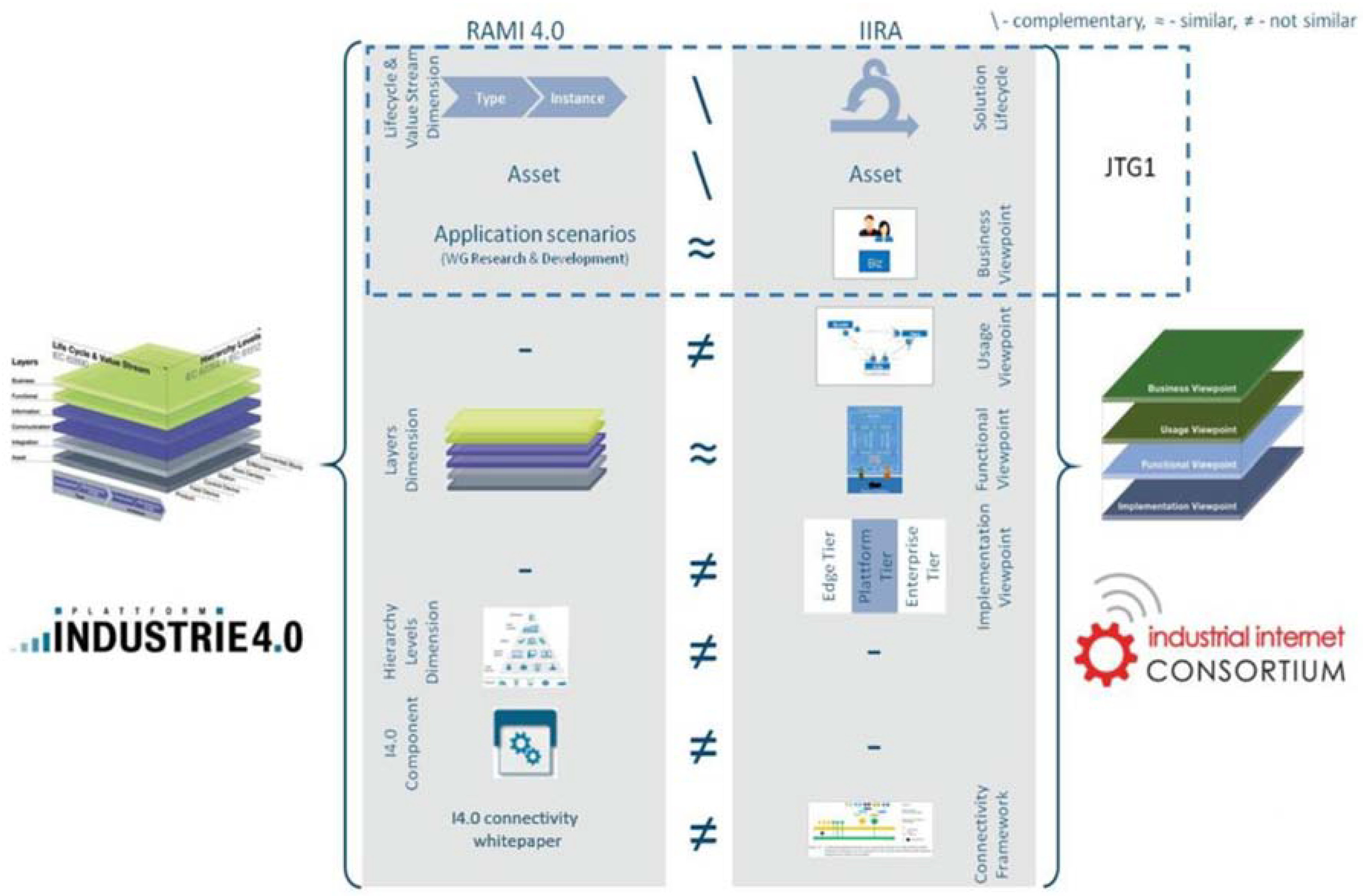
Two key industry consortia (the “German Platform Industrie 4.0” and the global not-for-profit partnership of industry—Industrial Internet Consortium (IIC)) built their reference architecture models for Industry 4.0, respectively, for industrial internet. Though their reference models differ from each other, they are interoperable [5]. A common goal of both reference models and a cooperation between the “Platform Industrie 4.0” and IIC represents an important step in global industrial digitalization process [6].
One important difference which needs to be highlighted is that the “Platform Industrie 4.0” defines the Industry 4.0 (I4.0) Component (Figure 1). This component is a kind of standardized refined IoT or industrial IoT (IIoT) device which fulfils Industry 4.0 requirements [7]. This could significantly reduce the effort to integrate such a device into I4.0 infrastructure. More about architecture alignment and interoperability between these two concepts can be find in [6].
All of this is not meant to neglect the other initiatives worldwide: the “Nouvelle France Industrielle” in France, the Connected Industry 4.0 in Spain, China Manufacturing 2025 in China, the Smart Manufacturing Leadership Coalition in the US, and the Japanese Robot Revolution Initiative. All of these initiatives have agreed to cooperate in the field of IoT/Industry 4.0 with the German initiative [8]. This fact, as well as the definition of the I4.0 Component, were the reasons why the “German Industrie 4.0” was chosen as a reference course for holistic approaches in the world of Industry 4.0.
This article understands the Industry 4.0 Component as defined by the “Platform Industrie 4.0” [5] as a reference for building I4.0 cyber-physical systems. By encapsulating the asset in an administrative shell, the asset becomes an Industry 4.0 Component. The AAS concept is based on the need for information exchange in the value chain among partners (suppliers, engineering partners, system integrators, operators and service partners) [9,10].
The main contribution of this study is the identification of the gap in the design and the implementation of embedded I4.0 Components. They are then filled by a procedure that has turned into an innovative methodology. This methodology allows developers and industrial manufacturers to implement assets (e.g., intelligent sensors, actuators, etc.) as embedded I4.0 Components, which can be easily integrated into a I4.0 network and current communication infrastructures.
2. Asset Administration Shell as Industry 4.0 Component
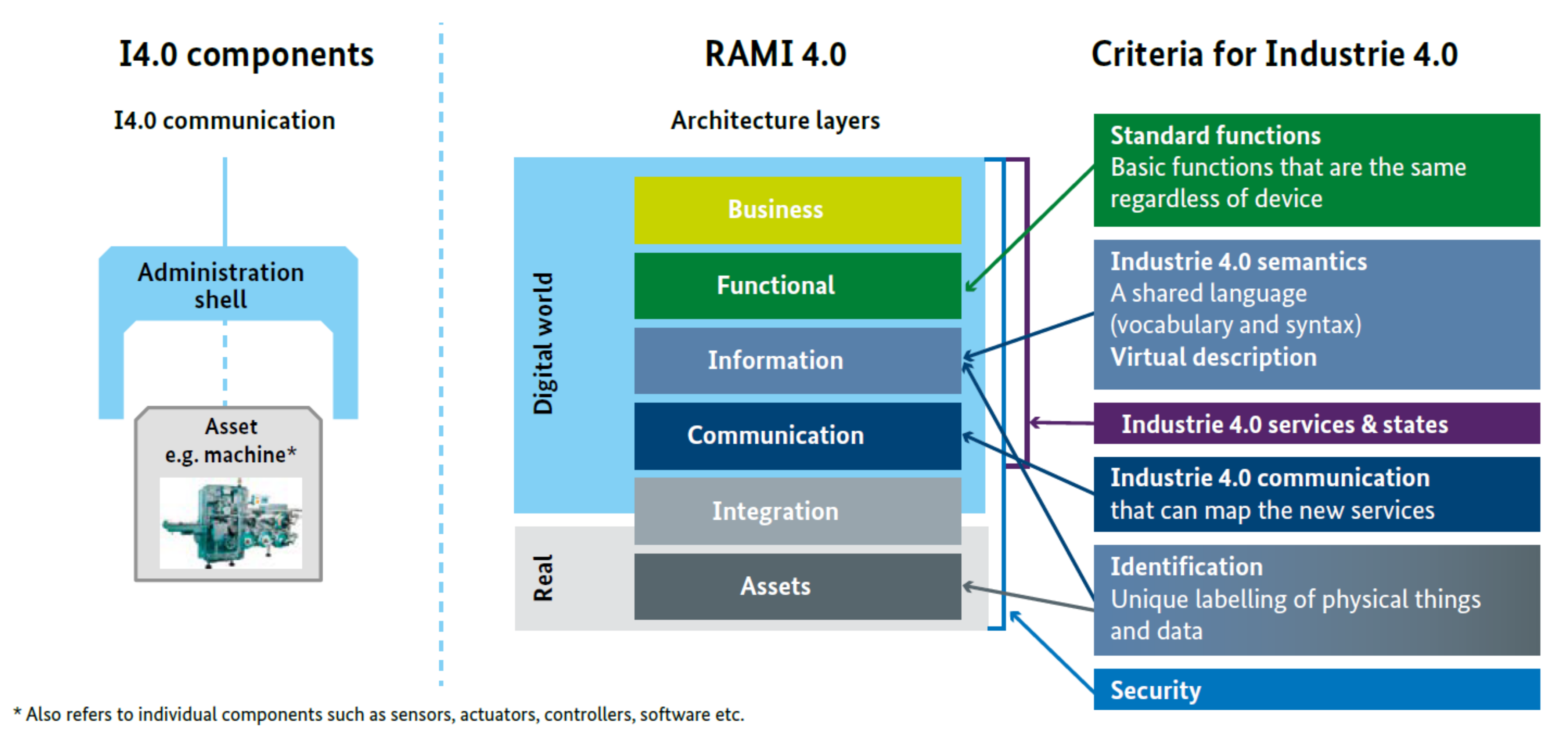
The text “An administration shell turns an object into an Industrie 4.0 component” comes from the document Implementation Strategy Industrie 4.0. This document deeply explains the Industry 4.0 Component concept in the perspective of the “Industrie 4.0” strategy and presents it as a specific case of a cyber-physical system [11]. Figure 2 depicts how criteria for “Industrie 4.0” are mapped over the RAMI 4.0 into the Asset Administration Shell [7].
The design of the administration shell is in compliance with general principles of the Digital Factory framework in accordance with IEC 62832-1 standard. Additionally, it could act as a digital twin at smart factories and deliver such advanced techniques as plug and produce [12,13].
A detailed overview about technology called digital twin (DT) is found in [12], where the lack of reference model for DT is recognized as one of the biggest challenges in DT research. This lack could be eliminated by AAS, since the AAS can implement a digital twin [14]. Another study [15] takes advantage of the AAS standardized abstract model to create a DT used in predictive maintenance. The very relevant research [13] discusses the utilization of AAS in combination with AutomationML and OPC UA to achieve the plug and produce functionality.
The main intention of this paper is to introduce the methodology for creating an embedded (or stand-alone) asset administration shell where the asset carries the administration shell and provides its information via communication that is compliant with I4.0. The main difference from the previously mentioned research is the direct usage of the OPC UA information model for modelling AAS and embedding the whole implementation of the OPC UA server, the core of the AAS, directly into the device, which operates with the real time operating system (RTOS). The embedded OPC UA server which carries the AAS could be for instance a 32 bit Arm Cortex M microcontroller. This enables creation of the “Embedded Industry 4.0 Component” for smaller and simpler devices. Obviously, this approach does not fit all applications [16], but generally it could simplify and accelerate the digitization process.
2.1. A Survey of Asset Administration Shell Tools Based on Practical Experiments
The specification in [9] refers to several tools for creation of an Asset Administration Shell. The most relevant opensource solutions for implementing an AAS are as follows:
By considering aspects (such as system requirements, interoperability and applicability) identified by authors as key factors, an evaluation was performed, the results of which are summarized in Table 1.
2.2. System Requirements
Owing to the .NET Core Framework and dockerizing, all solutions are platform neutral and are limited only by system requirements for the hosting device. The minimal system requirements are: 2 CPU Cores and 4 GB RAM for .NET Core, or 8 GB RAM for docker engine. Docker images size are between 200 and 700 MB, depending on the solution.
The testing aspect “Test hosting environment” provides information about the runtime environment where the AAS solution was deployed. The MS Windows environment was hosting AASX Server as the .Net Core application. Meanwhile, for the Ubuntu 18.04, the docker technology was used.
2.3. Interoperability
Interoperability is currently one of the crucial demands on communication and, in an asset administration shell, it is ensured by the AAS concept. The AAS model can be shared over the network via the Asset Administration Shell Package File Format (AASX) file or by application programming interface (API) [9,24]. The AASX file could be used for an initialization of the AAS server or for a static data exchange (as the AAS template, recipe, etc.); on the other hand, API can be used for creating an AAS on runtime or for updating variables’ values. Not having a possibility of using directly the AASX file is considered to be a disadvantage that decreases the overall interoperability. The AASX can be internally encoded in XML or JSON formats. The data encoded in XML or JSON and API are defined according to the specification in [9,24]. The communication interoperability is an aspect considered in “Natively supported API” (Table 1).
The NOVAAS solution offers publishing over MQTT, but to allow it, its own specific JSON encoding in AASX file is required. Thus, it cannot be considered as fully interoperable in MQTT.
The AASX Server offers MQTT as well. However, the .Net Core application does not start publishing over the MQTT automatically; from the available documentation, it is not clear if there is any application command to start publishing at the application runtime. The MQTT publishing was tested using AASX Package Explorer and it was discovered that whole submodels are published as one bulk JSON string. Moreover, topics are not generated to allow for submodel elements to be addressed individually, which seems to be a significant disadvantage in MQTT communication. The AASX Server also offers OPC UA communication, which extends its interoperability capabilities. However, if the value of an element is changed over OPC UA and the same element is observed via REST interface, the value change is not recognized by the REST API. Thus, it seems that the AASX Server has two servers’ instances: one for REST and one for OPC UA, and they are not interconnected for data exchange.
The MQTT publishing inside the Basyx solution seems not to publish the model automatically. Therefore, it was not possible to evaluate this communication. From the user point of view, the SAP I4.0 AAS solution complexity is high, and its documentation is not rich enough to explain how to use it. Thus, its communication was not tested.
The next evaluated aspect for the interoperability is the “Compatible with AASX Package Explorer” Table 1. The ASX Package Explorer contains a graphic user interface for designing AAS models which is a great benefit for the user who needs to create a model from the scratch. The NOVAAS solution is considered partially compatible because its MQTT publisher needs a specific internal JSON format of the AASX file. For the SAP I4.0 AAS solution, this evaluation is not applicable because it does not offer the possibility to load the AASX file. The other two solutions are compliant with the AASX file generated by AASX Package Explorer.
The last aspect from this group is “Has Web interface”. From the human point of view, it is nice to have this feature, but for machine communication it does not play a significant role.
2.4. Applicability
Another crucial aspect of the evaluation is unquestionably the solutions’ real-life applicability or in industrial production. The note “DOCKER image available” means that a compiler for creating a docker image is available directly in the AAS solution repository, which makes the solution deployment to a platform very handy.
Basyx and SAP I4.0 AAS have made great strides in this field because their solutions can be deployed as a platform, which includes components (or application adapters) to cover whole infrastructure [18,19]. Both solutions incorporate a database to store AAS models. In this manner, an asset administration shell can be available during its whole life cycle. The database also offers wide possibilities to digitize non-intelligent assets (electrical components, screws, etc.). The common grey field for all the above listed solutions is the Integration layer in RAMI 4.0 Architecture layers (Figure 2). A realization of data exchange between the real world or the field devices and the AAS is left on system integrators. However, OPC UA is strongly recommend.
2.5. Accessing Operational Values
All solutions offer the REST API to access AAS elements for reading and writing. However, the specification [24] defines standards for the API, the realization of which could require an additional application layer that could route semantic id of an API to its function call. Consequently, each solution has its own REST API routing, which requires additional integration effort if two AAS’s from different solutions need to communicate directly. Table 2 surveys the current state of the compatibility between the REST API calls.
If a third-party application needs to request data from AAS servers based on different solutions (NOVAAS, Basyx, AASX Server, etc.), then that application has to know what the destination server is based on and build the request accordingly.
2.6. Summary
All of the above solutions offer functional communication over REST API, which can be understood as a IoT or IIoT compliant communication. According to Table 2 there are differences in the REST GET requests’ syntax and in the request results. In terms of I4.0 interoperability, the solutions cannot be considered compatible. Based on overall results, the Basyx solution seems to be the most suitable candidate for a real application and is well documented. However, all solutions are portable as a docker image (similar to .NET Core); system requirements for its operation are counted in orders of gigabytes for RAM and disk space and in orders of gigahertz for the CPU. These system requirements could be considered as unreasonable or infeasible for low-cost automation intelligent sensors or actuators. To address this challenge, an innovative approach was proposed, which resulted into an original Asset Administration Shell design methodology.
3. Asset Administration Shell Design Methodology
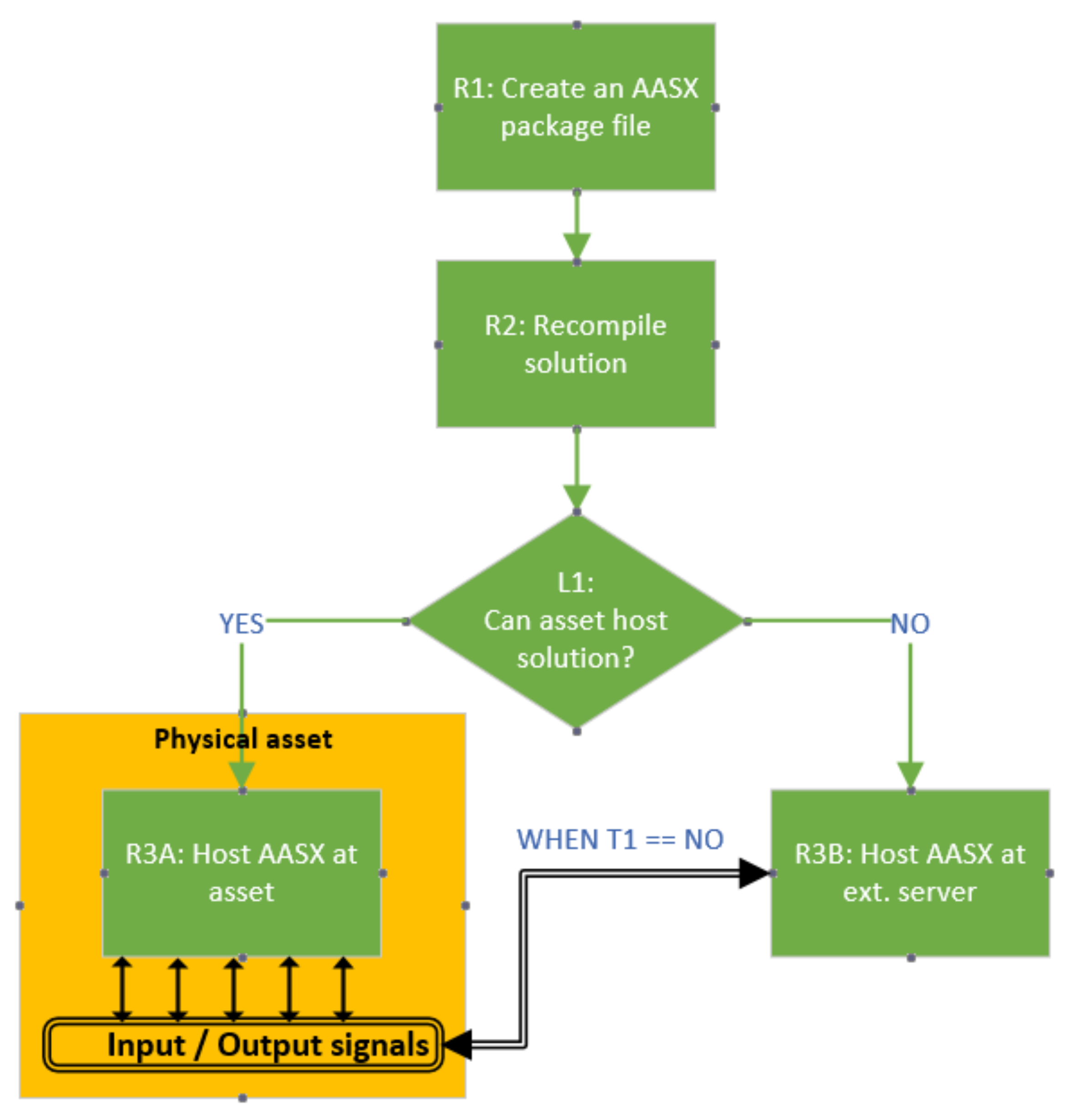
The proposed original AAS design methodology uses the asset administration shell package file and is mainly concerned with intelligent assets (i.e., assets with a connection to a network (e.g., intelligent sensors and actuators)). Before discussing challenges and limitations of available AAS opensource solutions, let us first describe the simplified workflow for AAS creation and deployment (Figure 3).
The challenge is to minimize the cost (which is the sum of the effort and the required computing power (Table 3)).
By introducing an embedded Industry 4.0 Component, it is possible to meet R3A (Table 3) and thus reduce the overall effort. Moreover, the use case discussed in this text reflects a demand for the Industry 4.0 Component, which is modular, small and affordable. These requirements run into the L1 limitation (Table 3). The use case describes the environmental sensor which provides three process values (ambient temperature, atmospheric pressure and relative humidity). The system requirements are 2 CPU cores, 8 GB RAM and tens of GB hard disk capacities, all of which are at least slightly exaggerated to provide just three values for the network. Certainly, with AAS manifest there are more data than three values. However, this cannot be an excuse for such invasive system requirements. To meet these requirements, we can benefit from the fact that administration shell is an abstract concept that can be described by UML, JSON, XML, AutomationML or a OPC UA information model [9,17,26,27,33].
3.1. OPC Unified Architecture as Asset Administrative Shell Realization Platform
The flexibility of the OPC UA address space concept [32] allows for the implementation of the AAS as an OPC UA information model [27,28,29,33]. The most advanced opensource development toolkits for OPC UA are UA-.NETStandard from OPC Foundation [34] and open62541 SDK [35]. While the former one relies on .NET technology (which requires Windows or Linux based operating system and adequate system resources), the latter one offers pure C language implementation (which requires only standard C libraries, TCP/IP and threading functions layers). Naturally, the open62541 SDK is a preferable choice if one of the implementation objectives is the minimization of system requirements.
The open62541 SDK declares that an OPC UA server with a minimized configuration can require less than 100kB of RAM and ROM [35], although the OPC UA server’s address space (which can cover the complexity of the AAS information model) requires much more. The OPC UA address space is composed of nodes and their relations [32]. Node relations provide a semantic description of the node and have the biggest memory footprint. For demonstration, the full namespace zero (which contains definitions from all OPC UA specifications [36]) requires around 4 MB of RAM. The open62541 SDK offers reduced namespace zero (which requires around 170 kB of RAM), but this namespace does not include definitions required by AAS. Therefore, a design of an on-chip embedded OPC UA server that serves a more complex AAS with some additional resource files (pictures or documentations, for instance) will eventually hit the limits of the space required for the memory on the silicon area of the chip. Therefore, it makes perfect sense to utilize external memories for storing program and runtime data.
3.2. Interoperability Provided by AAS Implemented in OPC UA Server
The virtual representation of an asset provided by administration shell contains the manifest, which can be regarded as a directory of the individual data contents. It therefore contains what is known as meta-information [11]. These meta-information data can serve as semantic meaning for data provided by AAS.
For operation values (ambient temperature, atmospheric pressure and relative humidity), concept descriptions [9] were defined to describe and identify them in AAS. The concept description can be extended with IEC61360 data specification content which allows for standardized semantic description of an AAS element. AAS offers several types of identifiers [9] which can be used for the unambiguous addressing of an element in the scope of administration shell, network or worldwide, depending on the purpose.
A notable identifier is the semantic id. For different AAS elements it has a slightly different function. In the case of a submodel, it points to semantic definitions (or concept description). A semantic definition can also be defined externally and can be referable by a global well-known semantic id. A good example is ECLASS, which contains a database of globally unique identifiers known as the International Registration Data Identifier (IRDI) [37].
4. Realization of the Embedded Asset Administration Shell
This section deals with the implementation of the embedded system as a component of I4.0 by utilizing AAS in combination with minimalist STM32 hardware, which is the first design and implementation of a device with such parameters. To achieve this objective, the above-mentioned methodology (where AAS is realized in OPC UA information model) has been applied.
According to the previous section, the hardware for the embedded AAS requires external memories to hold the program, runtime data and environmental sensors to gather data about ambient temperature, atmospheric pressure and relative humidity. The basic characteristics of hardware components are listed in Table 4.
The designed AAS describes the asset composed of the discovery board, which has the expansion board mounted on ARDUINO Uno connector.
4.1. Memory Organization of the Embedded OPC UA Server
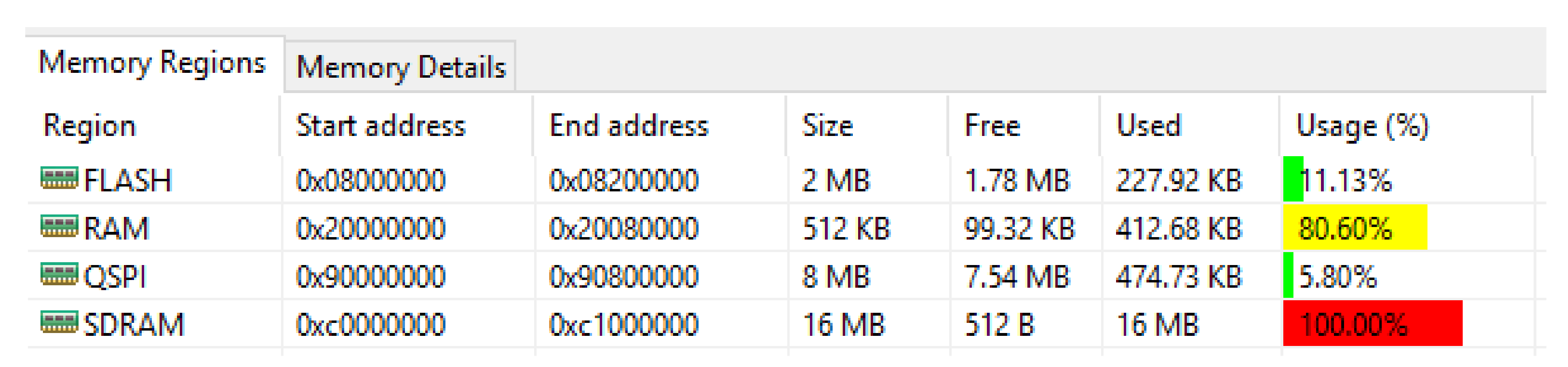
The open62541 reduced namespace zero was chosen as the base information model for the OPC UA server. This information model was extended to cover definitions required by the AAS information model. The extended information model with the actual OPC UA server implementation is amalgamated into a single C language source code. The AAS information model needs to be compiled into the C language source file as well. All C language source files are compiled using GNU compiler collection (GCC). GCC compiles C language source code to a binary file–program data, which are stored in the FLASH memory. During the program runtime, the program responsible for the address space creation runs and creates the OPC UA server address space in the heap memory stored in the RAM. Memory regions defined in GCC linker file are depicted in Figure 4.
The idea here is to store the OPC UA server and the AAS information model program data in external QSPI flash memory and create the OPC UA server address space in the heap memory, which is allocated in external SDRAM memory. The external SDRAM is slower, as the on-chip RAM it is used for storing the address space (which is not so dynamic as other processes). The overall OPC UA server address space, including the AAS information model takes around 640 kB only. The usage of RAM and SDRAM in the Figure 4 reflects only allocated addresses for heap memories.
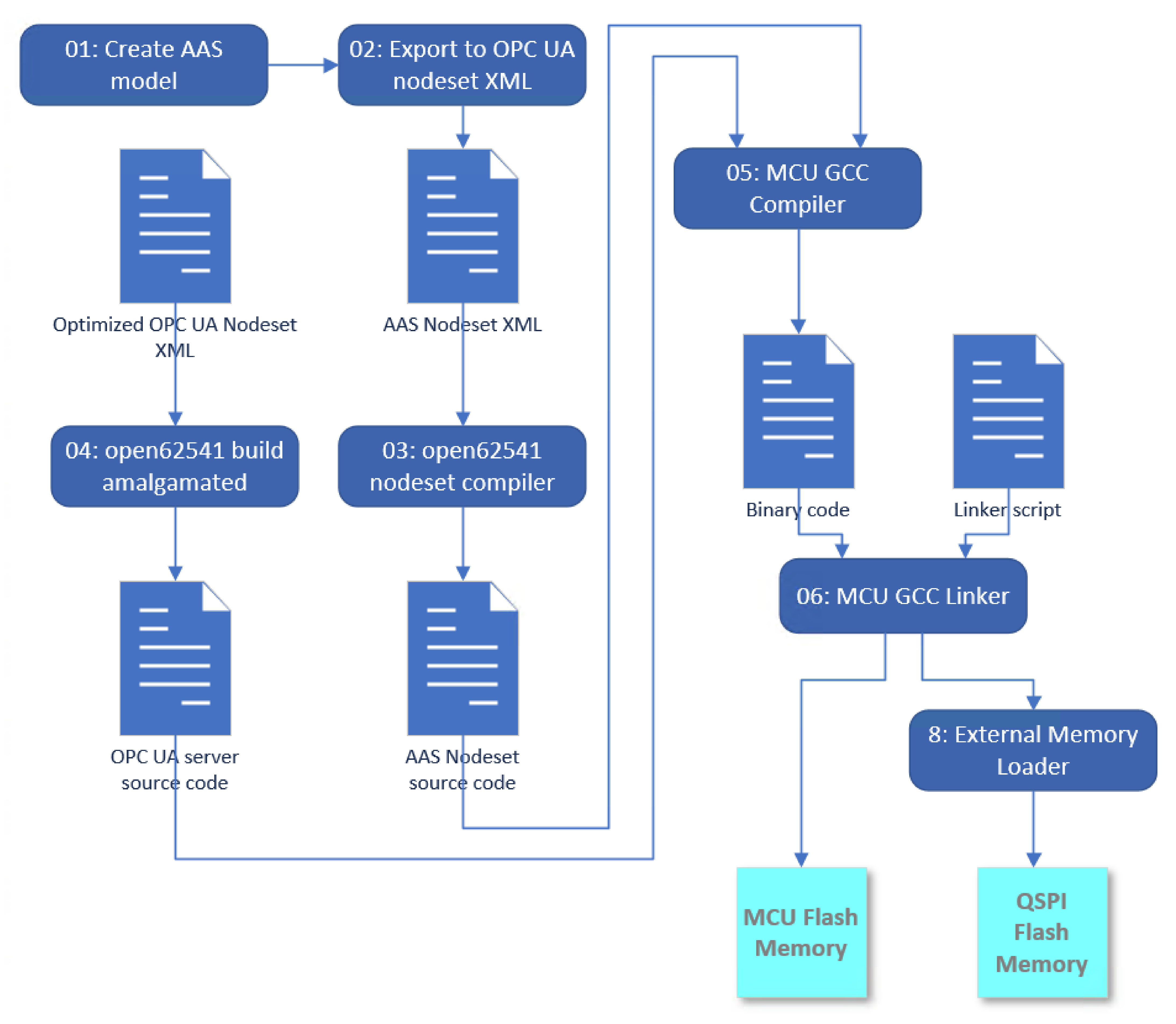
4.2. The Program Assembly Workflow
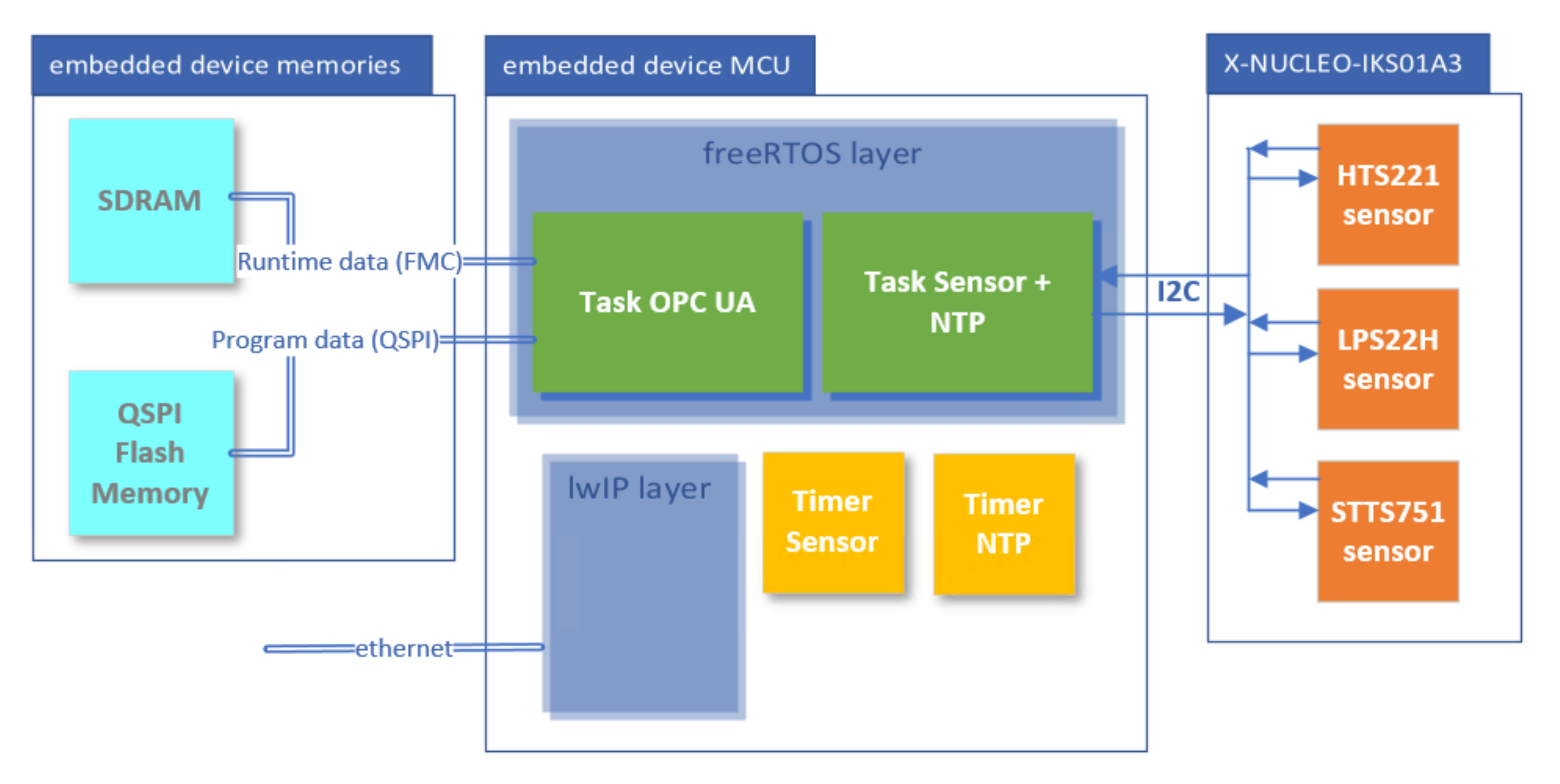
4.3. Thre Realization Workflow
The freeRTOS layer (Figure 6) is a middleware that implements the real time operating system in STM32 and enables multitasking. The Task OPC UA runs the OPC UA server. Program data are stored in the external Flash memory and are accessible over QSPI bus. The program creates the OPC UA address space in SDRAM, which is accessible over a flexible memory controller (FMC).
The Task Sensor + NTP (Figure 6) is dedicated to handling events raised by Timer Sensor and Timer NTP. When the Timer NTP is set, the task synchronizes the time of the OPC UA server with the network time protocol (NTP) server [41]. When the Timer Sensor is set then the task reads values from sensors and updates values of appropriate nodes in the address space. The communication between MCU and the environmental sensor is carried out over inter-integrated circuit (I2C) protocol.
The lightweight IP (lwIP) middleware (Figure 6) implements TCP/IP stack in STM32 and enables the communication over the network required for the OPC UA server and for the communication with the NTP server.
4.4. Summary
The presented methodology significantly reduces the integration effort and computing power requirements. The embedded device offers an advantage in that the data exchange between sensors or actuators can be performed directly at the device. By implementing the OPC UA server at the embedded device, the grey layer integration in Figure 2 is cleared up because the OPC UA is recognized as a communication device for Industry 4.0 and its address space can realize the administration shell.
5. Experimental Verification
The objective of this experiment is to prove that the embedded Industry 4.0 Component is built according to the proposed methodology works as designed, fulfilling the following points:
- offering a communication compliant with I4.0.
- providing data in AAS data structures, including measurements.
- providing AAS unambiguous identifier.
- using minimalistic hardware.
- operating reliably.
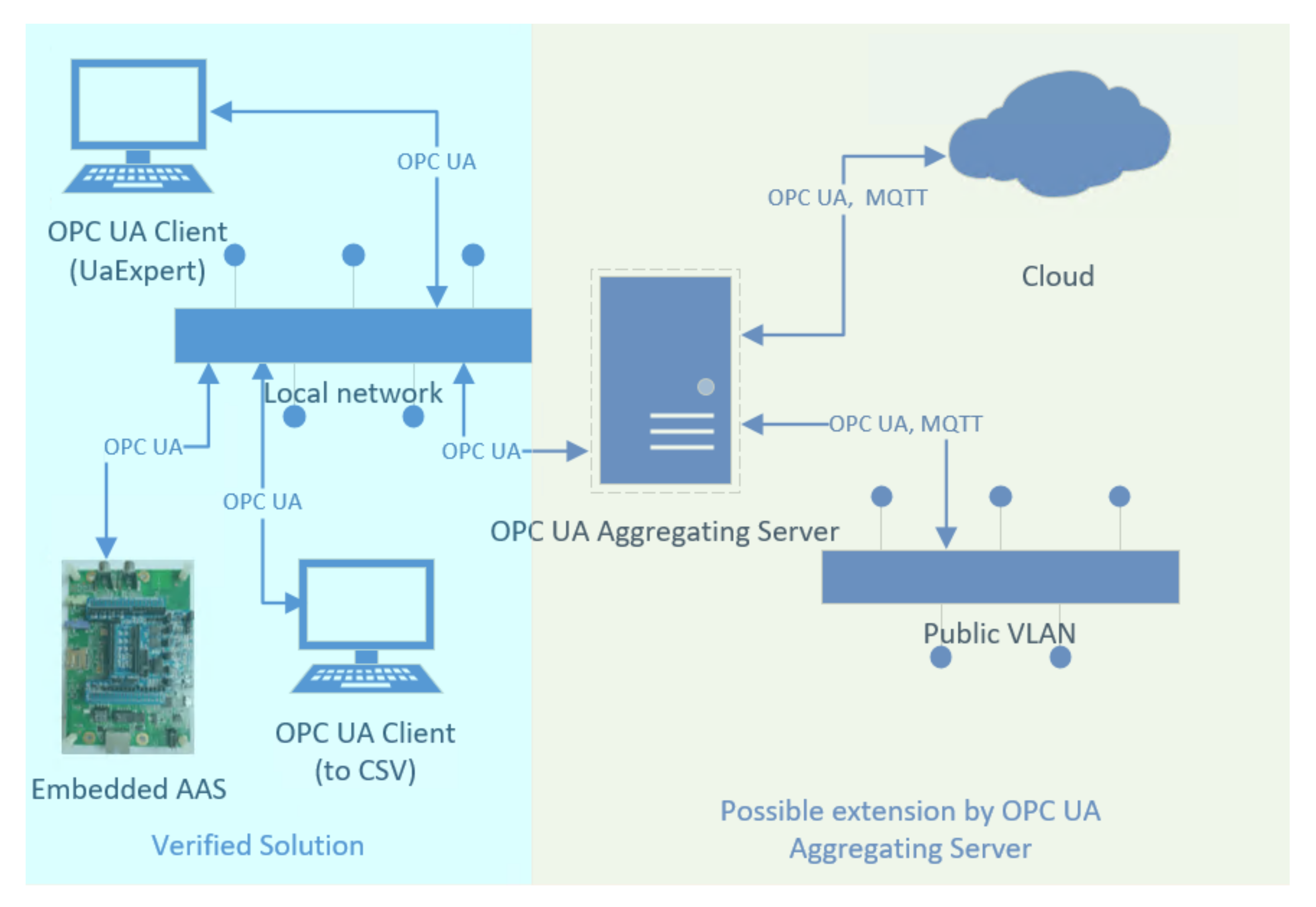
For these purposes, the testing environment based on the local network was established as depicted at the left-hand side of the Figure 7. Two OPC UA clients–the UaExpert [42], and the simple OPC UA Client based on open62541 SDK [35]—are connected with the Embedded AAS described in the previous section. The simple OPC UA Client labelled as “to CSV” writes operation data (temperature, relative humidity and atmospheric pressure) from embedded AAS into a comma separated values (CSV) file every 5 min.
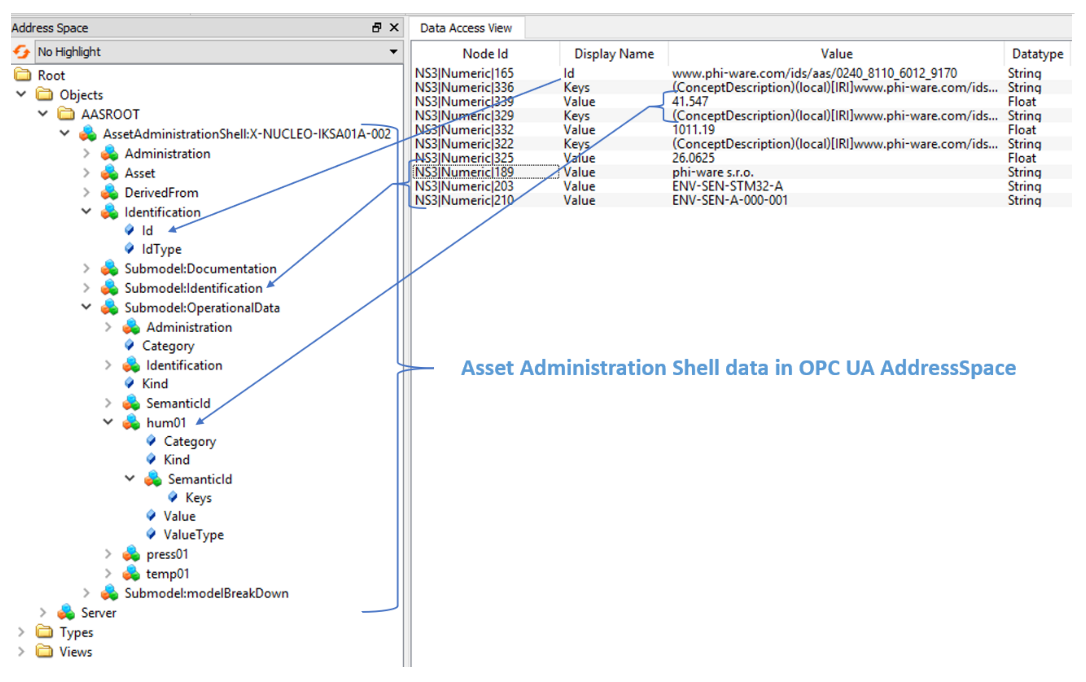
Figure 8 shows the UaExpert view demonstrating that operational data have a standardized format and are fully transparent for any OPC UA client. Each value can be identified by its semantic id. The AAS does not contain all submodels as listed in [38]; for our experimental purposes, the Documentation, Identification, modelBreakDown and OperationalData submodels are sufficient. The Documentation submodel carries documentation data, the Identification submodel contains data that identify the device in the I4.0 network (e.g., manufacturer, product code and serial number of the asset), the OperationData submodel provides runtime data and their identification (value and keys in Figure 8) and the modelBreakDown submodel represents the bill of materials. Finally, the value of Id (Figure 8) provides the unambiguous AAS identifier.
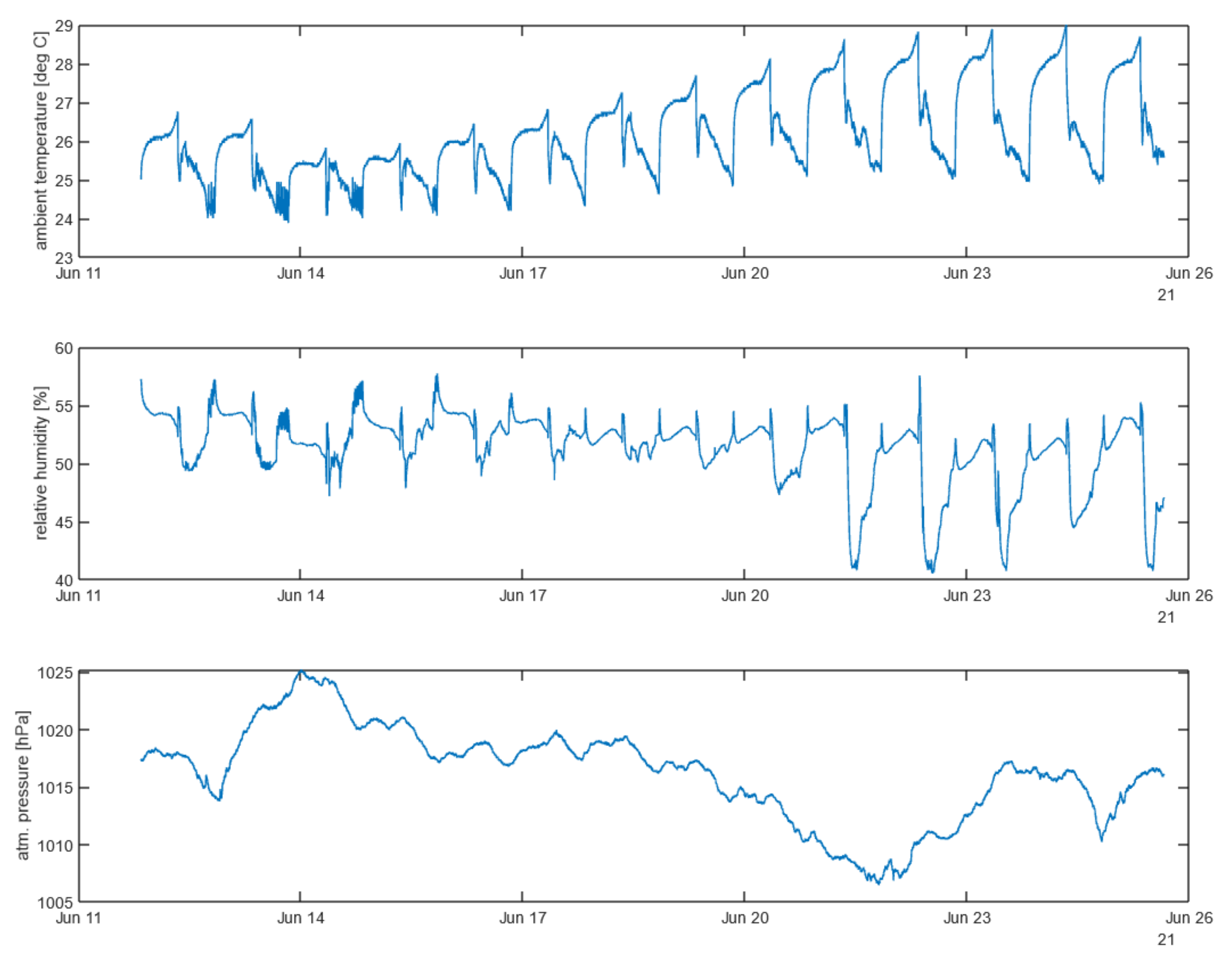
Figure 9 visualizes data acquired using the OPC UA Client (to CSV) according to Figure 7. Data acquisition had been continuously running in laboratory environment for more than 2 weeks (temperature peaks correspond to switching on/off the air conditioning in the laboratory).
The experimental verification proved that the proposed methodology guarantees a minimization of system requirements by implementing the AAS into the embedded device while maintaining interoperability and applicability.
6. Discussion
The presented methodology offers a possibility to implement the embedded AAS (or embedded I4.0 components). Compared with recent studies [13,28,29] (which implement a certain type of embedded AAS device), the system requirements of the embedded AAS proposed in this work are in the order of hundreds lower. This was achieved by utilizing freeRTOS in combination with ARM Cortex M7 MCU and the customized open62541 SDK memory management. This allows for the creation of a unique type of intelligent sensor that bears its AAS implementation. This is unlike the mentioned AAS realizations studies where the AAS is hosted by an external system or on embedded hardware that is significantly more powerful. Table 6 summarizes the highlighted properties of existing studies and solutions obtained from publicly available sources.
The aim of this summarization is to emphasize that the embedded AAS built according to proposed methodology differs from present implementations. For instance, to achieve comparable parameters in terms of providing AAS, solutions in [16,17,18,19,2828,29] require incomparably more powerful hardware or the actual AAS being implemented outside of the asset.
On the other hand, the study [13] is aimed at the deterministic communication achieved by the time sensitive networking (TSN), which is not the objective of semantic communication. In [30], the “Nano Embedded Device 2017 Server Profile” [31] is implemented even closer to bare metal in terms of hardware, but the system resources are not sufficient for AAS implementation in OPC UA server. For the moment, no AAS has been implemented at the commercial solution from Hilscher [43], but from the hardware perspective (and considering the fact that it uses the same SDK [35] as the methodology presented in this paper), it seems to be a promising candidate for an evaluation platform or AAS implementation in a production.
Limitations of proposed solution:
- Limited number of connected clients:The designed embedded AAS device is still limited by its performance which could be a drawback for its utilization (e.g., limited number of clients to connect).
- PubSub communications at the expense of losing service oriented architecture:OPC UA offers the PubSub communication model [44], which can solve the issue with a limited number of clients at the expense of losing service-oriented architecture.
Both previously mentioned limitations can be eliminated by introducing an OPC UA aggregating server as outlined in Figure 7.
The next objective of our research is to extend our study [41] to cover the situation wherein an aggregating OPC UA server aggregates OPC UA servers in a network. The challenge here is to provide a feature to enable querying a value by the semantic id. This could allow to query the value of OPC UA Aggregation Server Figure 7 by a semantic id without the necessity to know which AAS provides this value. In a broader sense, the value will be provided by a network rather than by the AAS. Practically, we are speaking about achieving plug-and-produce enabling in order to exchange a device for another without disturbing the upstream system.
7. Conclusions
The paper compares available opensource tools for AAS creation based on practical research and presents an original methodology for design and implementation of embedded AAS with an emphasis on minimizing computing power and effort.
In accordance with this methodology, the embedded AAS (which can be considered as an embedded I4.0 Component) was created using a OPC UA Micro Embedded Device 2017 Server profile [31] with the address space realizing the administration shell.
The developed method combined with the hardware (32 bit Arm Cortex M microcontroller) and OS (freeRTOS) make this device pioneering and the first embedded AAS with comparable parameters to our knowledge.
Thanks to the OPC UA architecture and the AAS concept in terms of communication and semantics, the presented methodology allows to create an embedded device that is interoperable in the network with I 4.0 components and meets I 4.0 requirements for data exchange. The realization of the embedded AAS described in this work can be valuable for manufacturers in designing intelligent sensors as embedded Industry 4.0 components; in this way, it can contribute to further accelerating the overall digitization of the industry.
Author Contributions
Conceptualization, R.P. and P.D.; methodology, R.P.; software, R.P.; validation, R.P. and L.B.; writing—original draft preparation, R.P.; writing—review and editing R.P., L.B. and P.D.; funding acquisition, P.D. All authors have read and agreed to the published version of the manuscript.
Funding
This research was funded by the Slovak Research And Development Agency, grant No. APVV-17-0190 and the Slovak Cultural Educational Grant Agency, grant No. 039STU-4/2021.
Data Availability Statement
Not applicable.
Acknowledgments
The paper was partially supported by the Slovak Research and Development Agency, grant No. APVV-17-0190 and the Slovak Cultural Educational Grant Agency, grant No. 039STU-4/2021. We would like to thank the phi-ware s.r.o. (which provided resources for virtual servers required for development and testing environments) and STM32 hardware.
Conflicts of Interest
The authors declare no conflict of interest.
References
- Jaloudi, S. Communication Protocols of an Industrial Internet of Things Environment: A Comparative Study. Future Internet 2019, 11, 66. [Google Scholar] [CrossRef] [Green Version]
- Cunha, M.J.; Almeira, M.B.; Júnior, R.F.F.; Carrijo, R.S. Proposal for an IoT architecture in industrial processes. In Proceedings of the 2016 12th IEEE International Conference on Industry Applications (INDUSCON), Curitiba, PR, Brazil, 20–23 November 2016. [Google Scholar]
- Rocha, M.S.; Sestito, G.S.; Dias, A.L.; Turcato, A.C.; Brandão, D.; Ferrari, P. On the performance of OPC UA and MQTT for data exchange between industrial plants and cloud servers. ACTA IMEKO 2019, 8, 80–87. [Google Scholar] [CrossRef]
- Jacoby, M.; Usländer, T. Digital Twin and Internet of Things—Current Standards Landscape. Appl. Sci. 2020, 10, 6519. [Google Scholar] [CrossRef]
- Pedone, G.; Mezgár, I. Model similarity evidence and interoperability affinity in cloud-ready Industry 4.0 technologies. Comput. Ind. 2018, 100, 278–286. [Google Scholar] [CrossRef] [Green Version]
- Lin, S.; Murphy, B.; Clauer, E.; Loewen, U.; Neubert, R.; Bachmann, G.; Pai, M.; Hankel, M.; Mellor, S. An Industrial Internet Consortium and Plattform Industrie 4.0 Joint Whitepaper Architecture Alignment and Interoperability 2017. Available online: https://www.plattform-i40.de/PI40/Redaktion/DE/Downloads/Publikation/whitepaper-iic-pi40.pdf?__blob=publicationFile&v=7 (accessed on 22 July 2021).
- Federal Ministry for Economic Affairs and Energy (BMWi). Which Criteria do Industrie 4.0 Products Need to Fulfil? 2019. Available online: https://www.plattform-i40.de/PI40/Redaktion/EN/Downloads/Publikation/criteria-industrie-40-products_2020.html (accessed on 23 July 2021).
- González, I.; Calderón, A.J.; Figueiredo, J.; Sousa, J.M.C. A Literature Survey on Open Platform Communications (OPC) Applied to Advanced Industrial Environments. Electronics 2019, 8, 510. [Google Scholar] [CrossRef] [Green Version]
- Platform Industrie 4.0. Details of the Asset Administration Shell—Part 1. 2020. Available online: https://www.zvei.org/en/press-media/publications/details-of-the-asset-administration-shell/ (accessed on 23 July 2021).
- Mendhurwar, S.; Mishra, R. ‘Un’-blocking the industry 4.0 value chain with cyber-physical social thinking. Enterp. Inf. Syst. 2021, 1–48. [Google Scholar] [CrossRef]
- Bitkom; VDMA; ZVEI. Implementation Strategy Industrie 4.0: Report on the Results of the Industrie 4.0 Platform; Bitkom: Berlin, Germany; VDMA: Berlin, Germany; ZVEI: Berlin, Germany, 2016; pp. 1–104. Available online: https://www.bitkom.org/Bitkom/Publikationen/Implementation-Strategy-Industrie-40-Report-on-the-results-of-the-Industrie-40-Platform.html (accessed on 23 July 2021).
- Lu, Y.; Liu, C.; Wang, K.I.K.; Huang, H.; Xu, X. Digital Twin-driven smart manufacturing: Connotation, reference model, applications and research issues. Robot. Comput. Integr. Manuf. 2020, 61, 101837. [Google Scholar] [CrossRef]
- Ye, X.; Jiang, J.; Lee, C.; Kim, N.; Yu, M.; Hong, S.H. Toward the Plug-and-Produce Capability for Industry 4.0: An Asset Administration Shell Approach. IEEE Ind. Electron. Mag. 2020, 14, 146–157. [Google Scholar] [CrossRef]
- Details of the Asset Administration Shell: From Idea to Implementation. Plattform Industrie 4.0, Ed. Available online: https://www.plattform-i40.de/PI40/Redaktion/EN/Downloads/Publikation/vws-in-detail-presentation.html (accessed on 22 July 2021).
- Cavalieri, S.; Salafia, M.G. A Model for Predictive Maintenance Based on Asset Administration Shell. Sensors 2020, 20, 6028. [Google Scholar] [CrossRef] [PubMed]
- Jacoby, M.; Jovicic, B.; Stojanovic, L.; Stojanović, N. An Approach for Realizing Hybrid Digital Twins Using Asset Administration Shells and Apache StreamPipes. Information 2021, 12, 217. [Google Scholar] [CrossRef]
- Admin-Shell-io/Aasx-Server. Available online: https://github.com/admin-shell-io/aasx-server (accessed on 23 July 2021).
- Eclipse BaSyx. Available online: https://www.eclipse.org/basyx/ (accessed on 23 July 2021).
- SAP/i40-aas. Available online: https://github.com/SAP/i40-aas (accessed on 23 July 2021).
- NOVA Asset Administration Shell. Available online: https://gitlab.com/novaas/catalog/nova-school-of-science-and-technology/novaas (accessed on 23 July 2021).
- Docker hub Stubafeirupr/Aasxserver-stm32. Available online: https://hub.docker.com/r/stubafeirupr/aasxserver-stm32 (accessed on 23 July 2021).
- Docker Hub Stubafeirupr/Basyx-stm32. Available online: https://hub.docker.com/r/stubafeirupr/basyx-stm32 (accessed on 23 July 2021).
- Docker Hub Stubafeirupr/Novaas-stm32. Available online: https://hub.docker.com/r/stubafeirupr/novaas-stm32 (accessed on 23 July 2021).
- Platform Industrie 4.0. Details of the Asset Administration Shell—Part 2. 2020. Available online: https://www.plattform-i40.de/PI40/Redaktion/EN/Downloads/Publikation/Details_of_the_Asset_Administration_Shell_Part2_V1.html (accessed on 23 July 2021).
- Admin-Shell-io/Aasx-Package-Explorer. Available online: https://github.com/admin-shell-io/aasx-package-explorer (accessed on 23 July 2021).
- Pribiš, R.; Beňo, L.; Drahoš, P. An Industrial Communication Platform for Industry 4.0—case study. In Proceedings of the 2020 Cybernetics & Informatics (K&I), Velke Karlovice, Czech Republic, 29 January–1 February 2020; p. 19472801. [Google Scholar]
- Cavalieri, S.; Salafia, M.G. Insights into Mapping Solutions Based on OPC UA Information Model Applied to the Industry 4.0 Asset Administration Shell. Computers 2020, 9, 28. [Google Scholar] [CrossRef] [Green Version]
- Arm, J.; Benesl, T.; Marcon, P.; Bradac, Z.; Schröder, T.; Belyaev, A.; Werner, T.; Braun, V.; Kamensky, P.; Zezulka, F.; et al. Automated Design and Integration of Asset Administration Shells in Components of Industry 4.0. Sensors 2021, 21, 2004. [Google Scholar] [CrossRef] [PubMed]
- Cavalieri, S.; Giuseppe, M.G. Asset administration shell for PLC representation based on IEC 61131-3. IEEE Access 2020, 8, 142606–142621. [Google Scholar] [CrossRef]
- Imtiaz, J.; Jasperneite, J. Scalability of OPC-UA Down to the Chip Level Enables “Internet of Things”. In Proceedings of the 2013 11th IEEE International Conference on Industrial Informatics (INDIN), Bochum, Germany, 29–31 July 2013; pp. 500–505. [Google Scholar] [CrossRef]
- OPC Foundation. OPC UA Profiles. Available online: https://profiles.opcfoundation.org/v104/reporting/ (accessed on 28 July 2021).
- OPC Foundation. OPC Unified Architecture Part 3: Address Space Model. Available online: https://opcfoundation.org/developer-tools/specifications-unified-architecture/part-3-address-space-model/ (accessed on 23 July 2021).
- Fuchs, J.; Schmidt, J.; Franke, J.; Rehman, K.; Sauer, M.; Karnouskos, S. I4.0-compliant integration of assets utilizing the Asset Administration Shell. In Proceedings of the 2019 24th IEEE International Conference on Emerging Technologies and Factory Automation (ETFA), Zaragoza, Spain, 10–13 September 2019; pp. 1243–1247. [Google Scholar]
- OPCFoundation/UA-. NETStandard. Available online: https://github.com/OPCFoundation/UA-.NETStandard (accessed on 26 July 2021).
- open62541. Available online: https://open62541.org/ (accessed on 26 July 2021).
- OPC Unified Architecture Specification. Available online: https://opcfoundation.org/developer-tools/specifications-unified-architecture (accessed on 26 July 2021).
- ECLASS. Available online: https://www.eclass.eu/en/standard/introduction.html (accessed on 27 July 2021).
- Admin-Shell-io/Questions-and-Answers. Available online: https://github.com/admin-shell-io/questions-and-answers (accessed on 26 July 2021).
- OPC Foundation. OPC Unified Architecture Part 6: Mappings. Available online: https://opcfoundation.org/developer-tools/specifications-unified-architecture/part-6-mappings/ (accessed on 23 July 2021).
- STMicroelectronics. Quad-SPI Interface on STM32 Microcontrollers and Microprocessors AN4760 Application Note. Available online: https://www.st.com/content/ccc/resource/technical/document/application_note/group0/b0/7e/46/a8/5e/c1/48/01/DM00227538/files/DM00227538.pdf/jcr:content/translations/en.DM00227538.pdf (accessed on 23 July 2021).
- Pribiš, R.; Beňo, L.; Drahoš, P. Implementation of Micro embedded OPC Unified Architecture server-client. IFAC-PapersOnLine 2019, 52, 114–120. [Google Scholar]
- Unified Automation. UaExpert. Available online: https://www.unified-automation.com/products/development-tools/uaexpert.html (accessed on 30 July 2021).
- Hilscher NETX 90. Available online: https://www.hilscher.com/products/product-groups/network-controller/asics/netx-90/ (accessed on 5 August 2021).
- OPC Foundation. OPC Unified Architecture Part 14: PubSub. Available online: https://opcfoundation.org/developer-tools/specifications-unified-architecture/part-14-pubsub/ (accessed on 28 July 2021).
Figure 1.
Differences between the “Platform Industrie 4.0” RAMI 4.0 and ICC IIRA reference models [6].
Figure 1.
Differences between the “Platform Industrie 4.0” RAMI 4.0 and ICC IIRA reference models [6].

Figure 2.
Mapping criteria of “Industrie 4.0” over the RAMI 4.0 into the Asset Administration Shell [7].
Figure 2.
Mapping criteria of “Industrie 4.0” over the RAMI 4.0 into the Asset Administration Shell [7].

Figure 3.
Workflow for AAS creation and deployment.

Figure 4.
The embedded OPC UA Server memory organization.

Figure 5.
Program assembly workflow.

Figure 6.
The realization workflow.

Figure 7.
Experimental environment layout.

Figure 8.
Embedded AAS OPC UA address space viewed by UA Expert OPC UA Client.

Figure 9.
Ambient temperature, relative humidity and atmospheric pressure gathered by embedded AAS.


Table 1.
Evaluated aspects of the AAS opensource solutions.
| Solution: | AASX Server | Eclipse Basyx | SAP I4.0 AAS | NOVAAS |
|---|---|---|---|---|
| Aspect: | ||||
| Host platform | Platform neutral, DOCKER image available [21] | Platform neutral, DOCKER image available [22] | Platform neutral, DOCKER image available | Platform Neutral, DOCKER image available [23] |
| Implementation technology | .Net Framework, .Net Core | JAVA, .Net Core, C++ | JavaScript, TypeScript, Go | Node RED |
| Test hosting environment | MS Windows | Ubuntu 18.04 | Ubuntu 18.04 | Ubuntu 18.04 |
| AASX package type | XML | XML/JSON | not available | JSON |
| Natively supported API | REST 1, MQTT 2, OPC UA 3 | REST 1, MQTT 2, OPC UA | REST 1, HTTP | REST 1, MQTT 2 |
| Compatible with AASX Package Explorer | yes | yes | not available | partially |
| Has Web interface | yes | no | no | yes |
| Database for storing AAS | no | yes | yes | no |
| Infrastructure | no | yes | yes | no |
1 REST get and set requests are not compatible between solutions or return different set of data. 2 MQTT slightly differs for individual solutions. 3 update of a variable over the OPC UA is not reflected in the variable value obtained by REST get request.
Table 2.
REST GET requests and results.
| Solution | REST GET Request | Result |
|---|---|---|
| NOVAAS | /aasServer/shells/{aasId}/aas/submodels/{submodelID}/submodel/submodelElements/{elementID}/ | The lowest level is a submodel element—a property in this solution. From the property’s JSON string, a value must be parsed out. |
| Basyx | /aasServer/shells/{aasId}/aas/submodels/{submodelId}/submodel/submodelElements/{seId}/value | The request can address the value directly. |
| AASX Server | aas/{aasId}/submodels/{submodelId}/elements/{seId}/value | The request can address the value directly. The {aasId} supports only the shortId. This is a drawback, because normally a shortId should be used only in the scope of AAS and not globally. |
Table 3.
Workflow description for AAS creation and deployment.
| Requirement/Limitation | Description | Cost: Effort  Computing Power  |
|---|---|---|
| Requirement R1 | Creation of the AASX package file (e.g., using the AASX Package Explorer [25]). This file will represent the asset, and in a broader context, could also be considered a digital twin. |  |
| Requirement R2 | Recompilation of the docker image or the solution source code in order to encapsulate the AASX file. |  |
| Limitation L1 | The asset sufficient computing power to host the AAS solution requires 2 CPU cores and 4 GB RAM for .NET Core, or 8 GB RAM for docker engine, and sufficient disk space ≈ 101 GB. | |
| Requirement alternative R3A | Hosting AAS solution directly at the asset requires L1 fulfilment. This is an advantage because I/O signals do not need to be transferred and can be processed directly at the asset. |  |
| Requirement alternative R3B | If the AAS solution needs to be hosted by an external server, then I/O signals need to be transferred over the network. This requires additional integration effort on the physical asset side and at the AAS side as well. |   |
Table 4.
Embedded Asset Administration Shell materials.
| Material | |
|---|---|
| STM32F769I-DISC1 STM32 discovery board | X-NUCLEO-IKS01A3 expansion board for STM32 |
| Features: 32 bit Arm Cortex-M7 MCU STM32F769NI 2 MB of Flash memory 512 KB of RAM Ethernet connection ARDUINO Uno connector 512-Mbit Quad-SPI Flash memory (on board embedded) 128-Mbit SDRAM (on board embedded) | Features: HTS221 humidity and temperature sensor LPS22HH pressure sensor STTS751 temperature sensor ARDUINO Uno connector |
Table 5.
Program assembly workflow description.
| Program Assembly Workflow Description (Figure 5) | |
|---|---|
| 01 | Create AAS model |
| The AASX Package Explorer is likely the most advanced opensource AASX editor with a graphic user interface. The AAS model was created in accordance with online guidance [38], as no official guidance exists. | |
| 02 | Export to OPC UA nodeset XML |
| The AASX Package Explorer offers the functionality to export AAS to OPC UA nodeset XML [39]. Currently, the export functionality has issues with exporting some types of AAS elements and their relations (ranges, entities, etc.) to OPC UA nodeset XML. Before compiling the nodeset into a C source code, some manual interventions are required. Adding missing AAS elements is beyond the scope of this work. | |
| 03 | open62541 nodeset compiler |
| The open62541 SDK contains a tool to compile the OPC UA XML nodeset to a C source file which contains a code to create AAS objects in the OPC UA address space [32]. | |
| 04 | open62541 build amalgamated |
| The open62541 SDK can amalgamate all functions and definitions required by the OPC UA server into a single source file which is ideal for embedded systems. The OPC UA server needs its nodeset to create the OPC UA server address space. The modified reduced namespace zero was used for this purpose. | |
| 05 | MCU GCC Compiler |
| It is important to use the GCC compiler containing all definitions required by the MCU. For this purpose, the STM32 Cube IDE was used. The STM32 Cube IDE includes the GCC toolchain suitable for this task. The MCU GCC Compiler compiles source files into the binary code. | |
| 06 | MCU GCC Linker |
| The Linker links object modules in the binary code into an executable program. It also loads the executable program into the memory in according to the Linker script file. Program parts residing in MCU memories are loaded by an internal memory loader. | |
| 07 | External Memory Loader |
| The part of the program which contains the OPC UA server and the AAS nodeset needs to be loaded to the external memory. For this purpose, the external memory loader is required. In this case, it is a separate program that communicates with the external memory over a quad serial peripheral interface (QSPI) bus [40]. | |
Table 6.
Studies and tools comparison.
| System Requirements (or Hardware) | AAS Embedded at Device | Available Communication | SOA 1 | Determ. Real Time 2 | OS | |
|---|---|---|---|---|---|---|
| Eclipse Basyx [18] | Raspberry Pi or equivalent | yes | REST, MQTT, OPC UA | yes | no | Independent |
| SAP I4.0 AAS [19] | Raspberry Pi or equivalent | yes | REST, HTTP | no | no | Independent |
| NOVAAS [20] | Raspberry Pi or equivalent | yes | REST, MQTT | no | no | Independent |
| AASX server [17] | Raspberry Pi or equivalent | yes | REST, MQTT, OPC UA | yes | no | Independent |
| Xun Ye [13] | n/a | no | OPC UA | n/a | yes | Linux |
| Arm Jakub [28] | Raspberry Pi or equivalent | yes | OPC UA | yes | no | n/a |
| Cavalieri Salvatore [29] | Raspberry Pi or equivalent | no | OPC UA, REST | yes | no | n/a |
| Jahanzaib Imtiaz [30] | TPS-1, <64 KB RAM | no | OPC UA | n/a | no | embOS |
| Embedded AAS (this paper) | 32 bit Arm Cortex M, <16 MB RAM, <4 MB disk | yes | OPC UA | yes | no | freeRTOS |
| Hilscher [43] | netX 90 scalable | ready3 | OPC UA | yes | no | n/a |
1 Service oriented architecture (SOA). 2 Deterministic real time communication. 3 The solution provides different hardware including external resources which are capable to carry on also AAS.
Publisher’s Note: MDPI stays neutral with regard to jurisdictional claims in published maps and institutional affiliations. |
© 2021 by the authors. Licensee MDPI, Basel, Switzerland. This article is an open access article distributed under the terms and conditions of the Creative Commons Attribution (CC BY) license (https://creativecommons.org/licenses/by/4.0/).
Share and Cite
MDPI and ACS Style
Pribiš, R.; Beňo, L.; Drahoš, P. Asset Administration Shell Design Methodology Using Embedded OPC Unified Architecture Server. Electronics 2021, 10, 2520. https://doi.org/10.3390/electronics10202520
AMA Style
Pribiš R, Beňo L, Drahoš P. Asset Administration Shell Design Methodology Using Embedded OPC Unified Architecture Server. Electronics. 2021; 10(20):2520. https://doi.org/10.3390/electronics10202520
Chicago/Turabian StylePribiš, Rudolf, Lukáš Beňo, and Peter Drahoš. 2021. "Asset Administration Shell Design Methodology Using Embedded OPC Unified Architecture Server" Electronics 10, no. 20: 2520. https://doi.org/10.3390/electronics10202520
Note that from the first issue of 2016, this journal uses article numbers instead of page numbers. See further details here.