
Multi-Domain Time-Sensitive Networks—Control Plane Mechanisms for Dynamic Inter-Domain Stream Configuration


Research Group Communication Systems, Ostfalia University of Applied Sciences, Salzdahlumer Str. 46/48, 38302 Wolfenbüttel, Germany
*
Author to whom correspondence should be addressed.
Electronics 2021, 10(20), 2477; https://doi.org/10.3390/electronics10202477
Submission received: 31 August 2021
/
Revised: 5 October 2021
/
Accepted: 6 October 2021
/
Published: 12 October 2021
(This article belongs to the Special Issue Emerging Technologies in Industrial Communication II)
Abstract
:Inter-domain communication in time-sensitive networks (TSN) has been identified as a requirement for various use cases. The TSN Toolbox provides standards for dynamic stream reservations, which is needed for, e.g., batch size 1 production, but these standards do not support the interaction on the control plane between multiple TSN domains. This paper presents control plane mechanisms for multi-domain time sensitive networks (MDTSNs) integrating an east–westbound protocol in the existing TSN control plane, in order to achieve multi-domain on-demand end-to-end bounded-latency TSN streams. Solutions for issues resulting from MDTSN, particularly the inter-domain forwarding offset, are presented. A proof of concept has been implemented and evaluated in a physical MDTSN test environment in order to prove the viability of the mechanisms developed.
1. Introduction
The IEEE 802.1 TSN Toolbox is rapidly growing. TSN extends Ethernet, as a pervasive networking technology, with features, such as bounded low-latency communication, time-synchronization, and on-demand stream reservation and configuration [1]. Currently, TSN profiles are specified describing combinations and configurations of TSN standards for various application areas (automotive, aerospace, etc.). In a use case specification of the IEC/IEEE 60802 TSN Profile for Industrial Automation (TSN-IA Profile) [2], the need for interconnecting TSN domains has been identified. One use case is described in which preconfigured industrial machines connected to one TSN domain require communication with devices located in other TSN domains. Each machine, production cell, production line, and production plant is located in its own interconnected TSN domain.
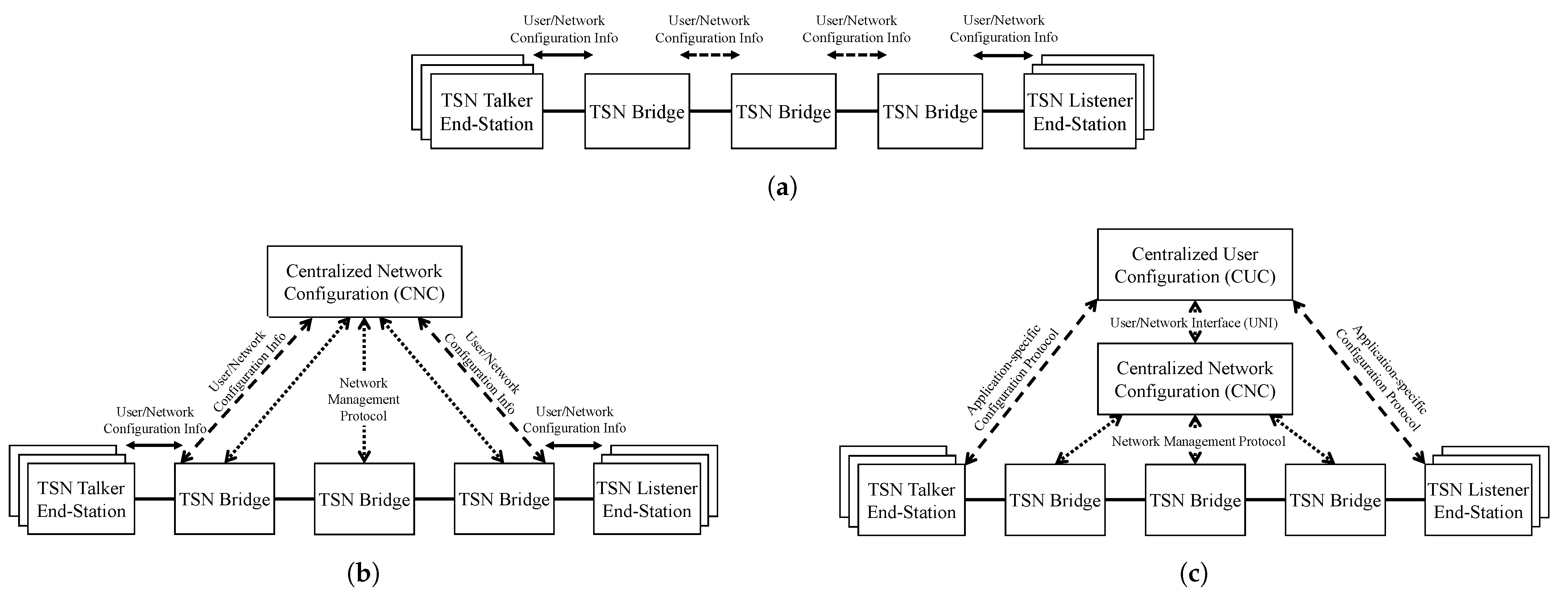
Wollschlaeger et al. pointed out that the manufacturing industry is expected to shift towards the distributed organization of production [3]. This requires highly manageable infrastructure components, which are deployed and changed on demand. Towards batch size 1 production, new challenges for network technologies emerge. Currently, real-time communication networks are engineered and statically configured to provide deterministic communications for one specific task. With changing communication requirements, the reconfiguration must occur in runtime. The IEEE 802.1Qcc [4] standard introduces three different configuration models for TSN; see Figure 1. The fully centralized model, which is in the focus of this work, describes a centralized user configuration (CUC) for dynamic stream requests and end-station configuration, while a centralized network configuration (CNC) calculates and configures network configurations (e.g., gate control lists) for all related TSN bridges.
Separating the data plane and the control plane, as inherited from software-defined networking (SDN) [5], the TSN control plane includes the CUC and the CNC, which configure the TSN data plane comprising the end-stations and the TSN bridges. The coalescing of information technology (IT) and operational technology (OT) to the Industrial Internet of Things (IIoT) requires an interface between the networks’ control plane [6]. Thus far, TSN standards describe domain boundaries, while the interaction of between different TSN domains has not been addressed yet.
Focusing on the fully centralized model of the IEEE 802.1Qcc standard, this work presents control plane mechanisms for multi-domain time-sensitive network (MDTSN) to provide multi-domain on-demand end-to-end bounded-latency TSN streams. We present a use case in which machines of different Manufacturing as a Service (MaaS) providers, located in their own interconnected TSN domains, perform physically cooperative tasks requiring communication between their robot control, dynamically established between the TSN domains using an east–westbound protocol. In [7], we presented an early-stage east–westbound protocol for the MDTSN control plane.
The work presented here addresses requirements for the realization of MDTSN and develops control plane mechanisms. In summary, each TSN domain configures a stream to the border TSN bridge of the next domain, while the east–westbound protocol is used to transmit the stream information to the next domain. Mechanisms for, e.g., sharing the requested maximum latency between all involved TSN domains within stream requests, are presented. A proof of concept (PoC) of the developed MDTSN control plane mechanisms has been implemented and tested in an MDTSN test environment, which shows the viability of the concept. Resulting issues are elaborated.
This paper is structured as follows: first, in Section 2, dynamic stream reservation in TSN is described. MDTSN use cases are presented in Section 3, while Section 4 presents related work. Section 5 presents the idea behind MDTSN and gives important aspects. Our concept for control plane mechanisms for the integration of an east–westbound protocol is presented in Section 6. Section 7 investigates the impact of MDTSN on the data plane. Section 8 introduces the PoC implementation used for the evaluation of the MDTSN control plane mechanisms developed. Section 9 evaluates the developed architecture and mechanisms. Section 10 concludes the paper and identifies future work.
2. Dynamic Stream Reservations in Time-Sensitive Networking
TSN specifies enhancements for IEEE 802 networks to guarantee deterministic communications. The standards can be combined in different ways. Low packet loss, low jitter, and a bounded latency are achieved using time slots (IEEE 802.1Qbv—Enhancements for Scheduled Traffic [8]). Traffic is divided into traffic classes (TC), which are assigned to time slots with cyclical repetition. A device configuration is specified in a gate control list (GCL), also called a schedule. The GCL defines the time-based opening and closing of gates of queues. An end-to-end connection in TSN is called a stream, which can be identified by, e.g., MAC addresses or IP addresses. All devices in a TSN network have to be configured properly to transfer frames of a TC in the exact time slot. This requires precise, network-wide time synchronization (IEEE 802.1AS-rev—Timing and Synchronization for Time-Sensitive Applications [9]). The IEEE 802.1AS-rev standard specifies the generalized precision time protocol (gPTP), which is based on the precision time protocol (PTP) [10], in the context of TSN.
2.1. Stream Reservation Protocol
In 2010, the Stream Reservation Protocol (SRP) (IEEE 802.1Qat—Stream Reservation Protocol) was published. The SRP describes an end-to-end stream reservation between end-stations with QoS guarantees. The protocol works on OSI layer 2, registers streams, and reserves resources along a path. Later, an amendment to SRP was published (IEEE 802.1Qcc—Stream Reservation Protocol (SRP) Enhancements and Performance Improvements). Besides performance improvements, the standard introduces three different architectural models, which will be described shortly.
Figure 1a shows a TSN network working in a decentralized manner, without any centralized configuration entities. Applications request their streams directly over the network by propagating the stream request along the topology using an user network interface (UNI). Each bridge along a path configures itself with the communication information provided in the request.
Figure 1b shows the centralized network/distributed user model. Due to rising complexities with the amount of devices and streams, a centralized network configuration (CNC) is introduced. With a global view on its domain, it has access to the network’s topology. Similar to the fully distributed model, streams are requested directly over the network using the UNI. The first bridge that detects a request forwards it to the CNC. This is responsible for path finding, schedule calculation and the configuration of all related bridges.
The fully centralized model, depicted in Figure 1c, focuses on complex use cases in which the talker and listener require configuration. Here, a centralized user configuration (CUC) is introduced that is able to discover end-stations and their capabilities. The CUC can also configure TSN features in the end-stations. Streams are requested directly at the CUC using an application-specific configuration protocol. The CUC translates stream requirements and communicates them to the CNC using the UNI. The CUC and the CNC are explained below in more detail.
2.2. Centralized User Configuration (CUC)
As a logical centralized entity, the main tasks of the CUC are to retrieve end-station capabilities, handle application stream requirements, communicate stream requests with the CNC, and configure end-stations according to scheduling results. Within a TSN domain, there may be multiple CUCs [11].
While the communication between the CUC and CNC is standardized by the IEEE, the communication between the end-stations and the CUC, addressed as the application-specific configuration protocol, is beyond their scope. OPC UA, as a machine-to-machine (M2M) communication protocol, developed by the OPC Foundation, already specified their PubSub architecture to be compatible with TSN [12]. They also specified an OPC UA-specific CUC called PubSub TSN Configuration Broker (PTCB) [13].
2.3. Centralized Network Configuration (CNC)
The CNC has a global view on the data plane of its domain and, therefore, knows all end-stations and network devices in its domain. It detects changes in the network (e.g., new end-stations). It receives stream requirements from the CUC to establish TSN streams between end-stations. For scheduled traffic, as described in IEEE 802.1Qbv [8], it performs path finding while computing schedules (shaper configuration) for each device on a path for each requested stream. Traffic scheduling is an NP-complete problem and has been the focus of research for many years [1,14,15,16]. Whenever the CNC finds a feasible configuration, which satisfies the stream request communication parameter with all its constraints (including the current configuration of all TSN bridges), it uses a management protocol, such as NETCONF, RESTCONF, or SNMP, to configure the new configuration to all related devices. It also provides a configuration to the CUC for the talker and listener of a stream. Other TSN features, such as the configuration of a credit-based shaper, frame preemption, per-stream filtering and policing, and the configuration of frame preemption, are also part of the CNC. Compared to the CUC, where multiple CUCs may exist within a TSN domain, there may only be one active CNC in a TSN domain [11].
In the TSN-IA Profile, the Industrial Automation Management Entity (IA-ME) as an adapted version of the fully centralized model is described. Besides the CUC and the CNC, it adds a Topology Discovery Engine (TDE), an Industrial Automation Path Establishment Entity (IA-PE) for the establishment and control of explicit paths through the network. Furthermore, a Best Management Entity Algorithm (BMEA) for the management of multiple IA-ME for, e.g., failover, is described, too. A Query Stream Server (QSS) handles stream requests, which are forwarded to the CUC. As the authors of the profile note, it is arguable that the TDE and the IA-PE can be considered part of the CNC and the QSS can be part of the CUC. In this document, the architecture described in IEEE 802.1Qcc is assumed.
2.4. Stream Request Procedure
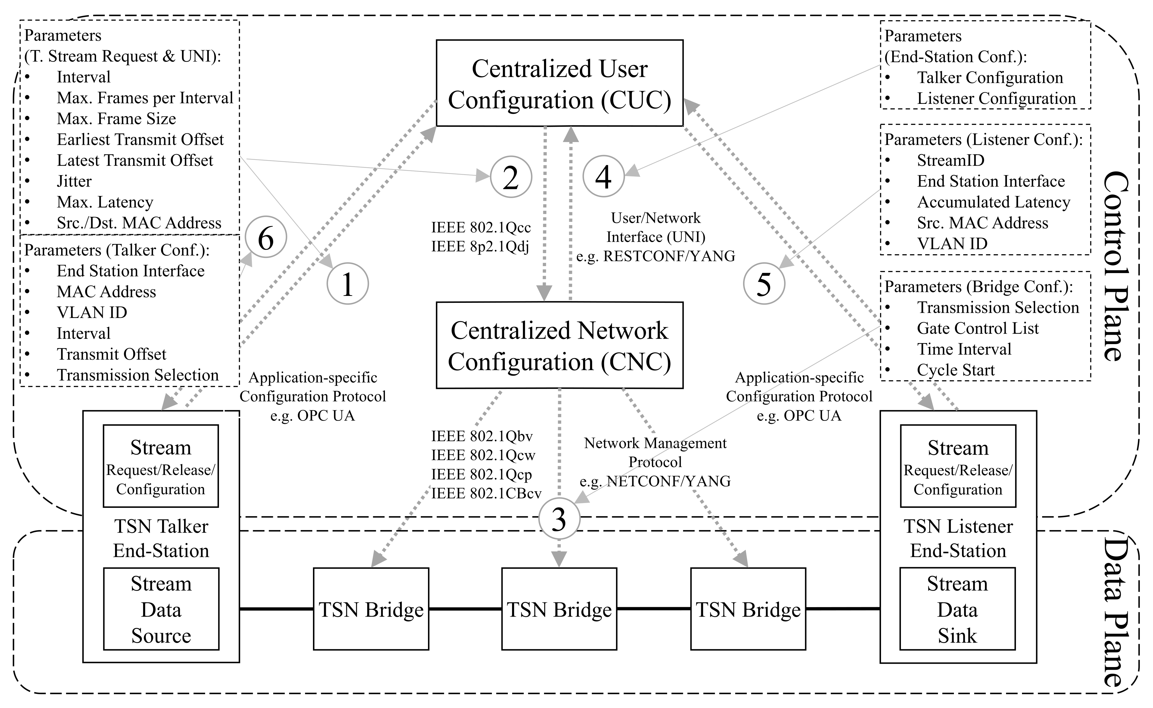
The fully centralized model separates the data plane and the control plane, an approach inherited from SDN [5]. Figure 2 depicts the separation, while showing the stream request procedure for a TSN stream in the TSN control plane. For each control plane message exchanged in the sequence, it shows most relevant parameters, as described in IEEE 802.1Qcc. Some parameters will further be described.
In a talker’s stream request, the time interval for the transmission of frames, the maximum number of frames per interval, and the maximum frame size are specified. The Earliest Transmit Offset (ETO) and the Latest Transmit Offset (LTO) specify the earliest and the latest offset within the network cycle (repetitive pattern of time slots) at which the talker is capable of transmitting its data. The Maximum Latency specifies the requested maximum latency from talker to listener for a single frame. For the talker configuration, after a successful stream request, a Transmit Offset is specified whose value is between the requested ETO and LTO.
For the listener configuration, the Accumulated Latency is used, which provides the achieved latency between a talker and a listener along the path. The CNC adds up the configured Bridge Delay and Propagation Delay of each bridge along the path to compute the accumulated latency. For a successful stream request, it must be lower than the requested maximum latency.
The reference plane specifies the boundary between the network media and the physical medium, as specified in IEEE 802.1AS [9]. Timing considerations in this work refer to this reference plane.
2.5. Traffic Types
In the current draft (1.2) of the TSN-IA Profile, different TCs and their communication requirements have been specified in the context of industrial automation [2]. The TC with the strictest communication requirements is isochronous traffic, used particularly for control-loop communications. This periodic traffic type, with typical fixed application data sizes of 30–100 bytes, has an application cycle (data transmission interval) from 2 ms down to under 100 s for, e.g., motion control. The maximum latency for the data delivery is usually within one application cycle. For this TC, the end-stations (applications) are required to be synchronized to the network clock and the network cycle for consistent delivery. The jitter must be minimal, which requires the TC to not interfere with other TCs. Isochronous traffic has a strict deadline (point of time), and messages may be discarded if they arrive too late.
The next TC in the profile is cyclic–synchronous, which has slightly less strict communication requirements. This periodic TC has a fixed application data size of 50–1000 bytes, with a period length between 500 s and 1 ms. The maximum end-to-end latency is also usually within a period, while this TC can handle a small jitter.
The remaining TCs target traffic for alarms and events, configuration and diagnostics, network control, audio, video, and best effort. All of them have less strict communication requirements. They can be implemented within TSN using strict priority from IEEE 802.1Q. Isochronous traffic and cyclic–synchronous traffic require exclusive gating within IEEE 802.1Qbv, as well as IEEE 802.1AS-rev, for time synchronization [17]. Furthermore, this document focuses on these two TCs.
To reduce latency for these very time critical TCs, OSI Layer 7 application data can be transferred as direct payload of OSI Layer 2 frames, so as to eliminate the increased latency caused by OSI Layer 3 and higher. In this case, IP addresses are not available. OPC UA supports the transport of OPC UA messages as direct payload of OSI Layer 2 frames [18], as further focused on in this document.
3. Use Cases
This section describes use cases that have been identified by the IEC/IEEE 60802 project, while another use case, identified by the authors, is described in more detail. The use cases have different requirements, which are highlighted at the end of the section.
In the IEC/IEEE 60802 project, which specifies the TSN-IA Profile, over 35 industrial use cases have been identified [19]. One use case is described in which preconfigured machines of one TSN domain, whose internal communication has been tested and approved, are required to communicate with devices located in other TSN domains. Each machine, production cell, production line, and production plant is located in its own interconnected TSN domain. Technically, one or more TSN domains may be part of an OSI layer 2 broadcasting domain, which may share a common time domain.
“Manufacturing processes are provided as a service when offering “Manufacturing as a Service”: the machine does not change ownership, and only the service of the machine is paid for (for example in the form of a cost-per-uptime model). What applies to complete production systems will, in the future, also hold true for individual elements within a manufacturing facility—for robots, for example.”[20]
Within MaaS, companies can outsource the manufacturing process of their product to a MaaS provider. These providers may use, e.g., predictive maintenance, for their systems in order to reduce down time by making use of monitored data from their customers’ robots. Relying on a single MaaS provider may lead to a vendor lock-in. Furthermore, different MaaS providers may have different specialities and pricing for certain production tasks. To remain independent, a combination of multiple MaaS providers should be intended. The use of open standard solutions (e.g., TSN, OPC UA, and AutomationML [21]) offers interoperability and allows communication between machines of different vendors.
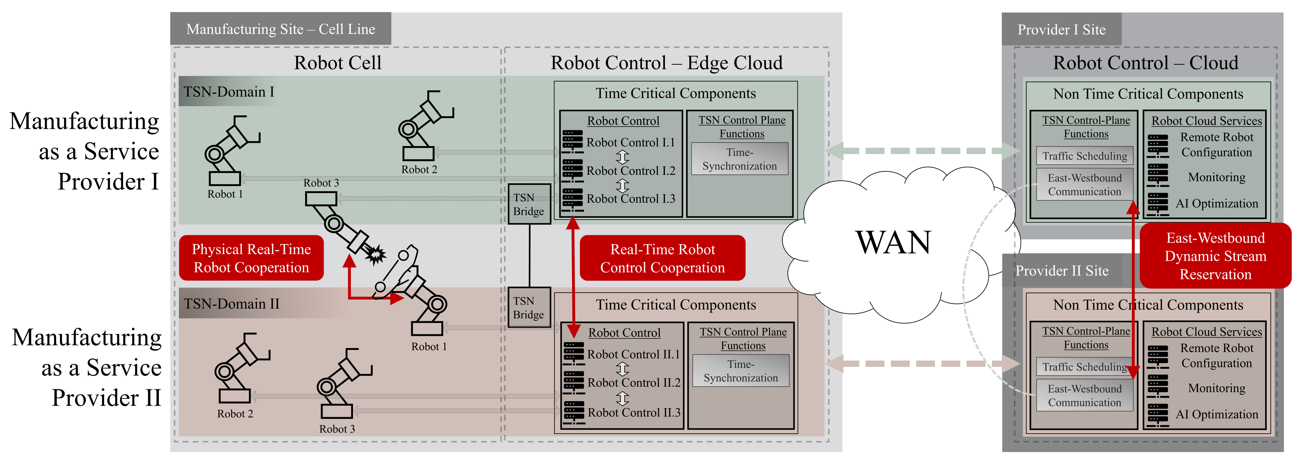
The use of multiple MaaS providers is visualized in Figure 3. The scenario takes place in a manufacturing site, in a production cell line. The network communication is based on TSN. Each MaaS provider brings its own individual solution. This includes robots located in the robot cell. The control of these robots requires on-demand end-to-end real-time communication, which is located in an on-premise edge cloud. Other time-critical components, such as time synchronization are located there, too. The edge cloud is configured and controlled from the MaaS providers’ robot cloud, connected via WAN, where all non-time-critical components are located. This includes the configuration of the local robot control and the traffic scheduling and configuration of the network. The cloud may also be used for monitoring the production systems, while the collected data are used to train a provider-specific AI optimization, for example, predictive maintenance. The overall concept and implementation of the service provider is part of their business secrets and are kept confidential. Therefore, each provider is located in its own TSN domain.
When combining multiple MaaS providers, they need to interact at different points, as highlighted in red color in Figure 3. In the robot cell, there is a physical real-time cooperation required between robots when producing a product in cooperation. The physical cooperation requires communication streams between the robot control systems of the providers. Due to the fact that each of the components of the providers is located in its own TSN domain, a physical connection between the domains is required. Within the connected TSN domains, communication streams with a bounded latency can be configured between the cooperating robot controls. The dynamic configuration of the streams is implemented using an east–westbound communication protocol located in the control plane, where stream reservations are negotiated between the TSN domains.
Compared to the use cases presented in IEC/IEEE 60802, this use case has different requirements. The internal TSN domain configuration must stay hidden, i.e., topology hiding. Multiple TSN domains can, therefore, not form an OSI layer 2 broadcast domain. Each multi-domain stream has to be requested and configured separately, as further described in this document.
4. Related Work
For SDN, several interfaces are defined [5]. One of them is the southbound interface, which handles the communication between the control plane and the data plane for, e.g., pushing forwarding rules to SDN switches. The defacto standard protocol here is OpenFlow. For the communication between distributed controllers, east–westbound protocols are used for, e.g., network state synchronization. In 2012, an east–westbound protocol for SDN, called SDNi, was presented [22]. The expired IETF draft specified a message exchange protocol across multiple SDN domains. The sketched protocol proposed domain-specific policies, reachability information exchange, and coordinated flow setups including QoS. Since then, there has been a great deal of research on east–westbound communication in SDN [23,24], focusing on topics, such as fault tolerance, high availability, or load balancing. Nonetheless, there is no standardized protocol, which is needed for compatibility and interoperability.
Phemius et al., for example, proposed DISCO (DIstributed Sdn COntrol plane) [25], where multiple SDN controllers from different SDN domains exchange topology information for an aggregated network view on each controller. They differentiate between intra-domain functionalities, responsible for the local domain, and inter-domain functionalities for, e.g., flow configuration between domains. Bagci et al. [26] extended an SDN controller with multi-domain controller-to-controller features. They implemented end-to-end service-level management supporting three different service levels (guaranteed quality, best effort plus, best effort), which were used for end-to-end service negotiation.
In the context of the TSN control plane, Schriegel et al. proposed a distributed SDN control plane for heterogeneous TSN (integration of PROFINET and TSN into SDN) requiring inter-domain communication [6]. Cascaded CNCs enable communication across multiple domains. The authors pointed out that, without any communication between the cascaded CNCs, which do not exchange timing and scheduling information, the end-to-end latency increases. Besides the idea of cascaded CNCs, their work did not cover how the cascaded CNCs can achieve an end-to-end stream.
There have been some contributions within the IEC/IEEE 60802 working group. Chen et al. proposed CCP (Config-entity to Config-entity Protocol alternatively CNC to CNC Protocol), as an idea for a protocol between CNCs. The authors mentioned that protocols, procedures, and managed objects for CCP need to be specified [27].
Steindl et al. consider TSN domains as black boxes, where each domain is responsible for stream establishment and teardown within its domain. They propose a domain management function (DMF) entity, which establishes TSN inter-domain streams from domain to domain, while it has no knowledge about internal domain information, e.g., bridges, streams, and resources. The DMF also has domain discovery and path computation functions [28].
Similar to the mechanisms presented in Reference [25], in cluster based routing for ad hoc networks, it is differentiated between intra-cluster and inter-cluster routing [29]. Clusters are organized by cluster heads, which are interconnected via border nodes. Cluster based routing does not focus on real-time communication and, therefore, does not exchange timing information when establishing inter-domain connections.
While the need for inter-domain communication in TSN has already been addressed, besides some ideas, to the best of our knowledge, there have not been any concrete protocols or procedures published yet.
5. Multi-Domain Time-Sensitive Networks (MDTSNs)
A TSN domain specifies a set of network bridges and end-stations that support a set of common TSN standards, sharing a common management model within one administrative domain [2]. In the context of this work, a TSN stream refers to an end-to-end communication using the IEEE 802.1Qbv standard for scheduled traffic. In the IEEE 802.1BA standard for audio video bridging, the use of multiple AVB domains is described [30]. End-stations within one AVB domain, which utilize the fully distributed TSN configuration model, can communicate with each other. The standard states that domain boundaries are detected automatically, when a network port of a station detects a different SRP domain. In the fully centralized model of the IEEE 802.1Qcc standard, TSN domains are formed by connecting TSN bridges to the respective CNC.
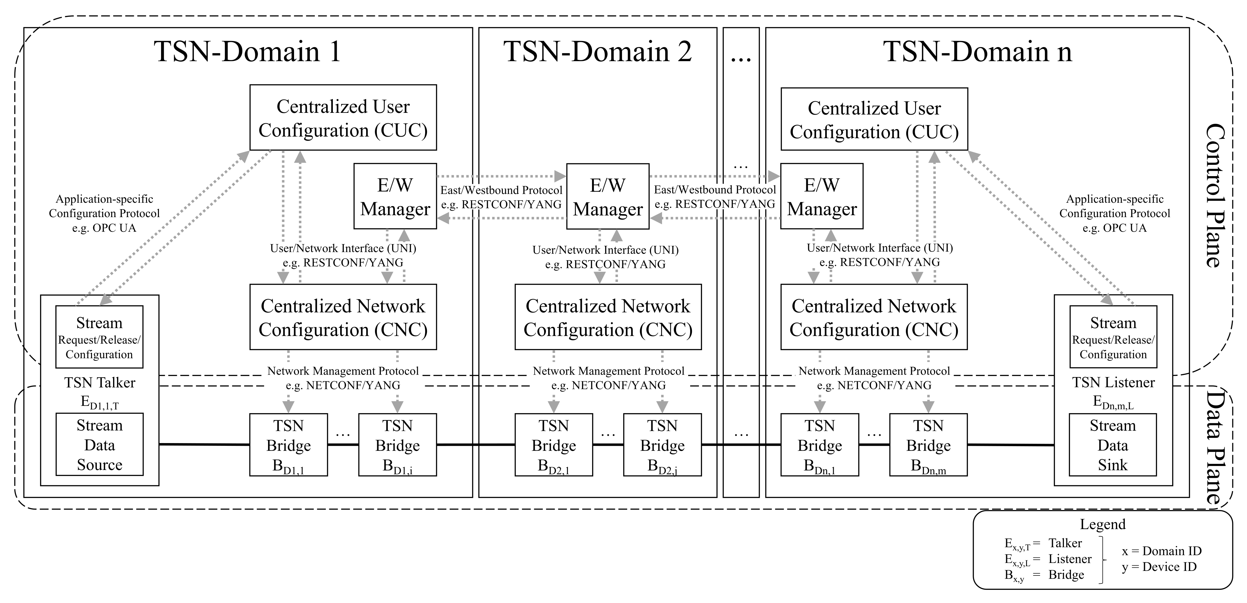
MDTSN on-demand end-to-end TSN streams have to be set up between end-stations of different TSN domains. Therefore, the interconnection mechanisms between the control plane network elements of the different domains, as well as the interaction between the data plane network elements of the different domains, have to be defined. The control plane architecture for multiple domains can be divided into the horizontal architecture, where controllers of different domains communicate directly with each other, also known under the term peer-to-peer, and the hierarchical architecture, where a root controller handles all inter-domain events [24]. The solution elaborated here focuses on the horizontal architecture, particularly because of its advantages with respect to topology hiding. Figure 4 depicts an MDTSN in a horizontal architecture. In the MDTSN control plane, domains are connected via east/westbound managers communicating over an east–westbound protocol. Different from east–westbound communication in SDN, an east–westbound protocol for TSN also requires the exchange of timing information for dynamic stream configurations.
Important aspects for MDTSNs are as follows:
- Concepts for MDTSNs should preferably be developed in a way that existing TSN standards need not to be modified, but MDTSN extensions build on it. The MDTSN concept presented here fulfills this requirement.
- TSN domains require an unique identifier [28].
- All stream requests of end-stations have to be sent to their local CUC, independent of the domain in which the destination end-station of the stream request is located, i.e., end-stations need not to know in which domain other end-stations are located.
- Broadcast traffic has to remain inside a domain to maintain topology hiding.
- Time synchronization between different TSN domains is required for MDTSNs.
6. Control Plane Mechanisms for MDTSN
This section proposes an east–westbound protocol to be integrated into the fully centralized MDTSN control plane. The presented control plane mechanisms enable stream configurations between two end-stations located in different TSN domains.
Three different roles of domains can be identified in a stream request. The source domain is the domain in which the talker is located. The forwarding domain is a domain in which neither the talker nor the listener is located. In the event that this domain type has no end-stations, its only purpose is interconnecting other TSN domains. The destination domain is the domain in which the listener of a stream request is located.
Each domain involved in an MDTSN stream request provides a TSN stream as a segment of the MDTSN end-to-end stream. The source domain provides a stream between the talker and the boundary port. Boundary ports are network ports of TSN bridges that interconnect two domains. Each forwarding domain provides a stream between the boundary ports, and the destination domain provides a stream between the boundary port and the listener. Each domain passes the timing information of that stream to the next domain.
6.1. Reachability Information Exchange
In TSN, only the CNC has information about the network’s topology. For MDTSN stream requests, the E/W Manager, as a separate entity, needs reachability information, which has to be exchanged using an east–westbound protocol. On the other hand, exchanged information should be limited as far as possible to achieve topology hiding. The following information is required:
- Topology of domain interconnections.
- MAC addresses of boundary ports of directly connected domains.
- List of local end-stations, which are made visible for multi-domain communication.
- List of (disclosed) end-stations of directly or indirectly connected domains.
6.2. Inter-Domain Path Finding
In more complex MDTSN scenarios with multiple forwarding domains and path alternatives, the need for inter-domain path finding emerges. This requires the exchange of existing domain interconnections. Exchanging information, such as the utilization of domains, may lead to a more optimal paths with an increased probability of a successful MDTSN stream setup. However, the east–westbound protocol presented here is agnostic to path finding algorithms.
6.3. Stream Parameter Determination
Section 2.4 presented the parameters involved in a local stream request. For MDTSN stream requests, some parameters have to be determined for each domain involved. While parameters, e.g., the source and destination address, the interval, the maximum frames per interval, and the frame size, stay end-to-end unchanged for an MDTSN stream request, parameters for time awareness must be individually determined per domain passed through.
Traffic scheduling, as a task of the CNC, can be computationally complex, depending particularly on the number of bridges and currently configured streams in the domain. Unsuccessful stream requests may occur, when the traffic schedule utilization in the respective domain is high and the stream request requirements are strict, e.g., small requested maximum end-to-end latency. For multi-domain stream setups, after one domain in the end-to-end path finds a feasible configuration, timing information, including the remaining maximum latency, is passed to the next domain. For each domain, it may be the case that no configuration meeting the stream request requirements can be found, resulting in a rejection of the stream request.
In order to reduce the computational load on the control plane, an appropriate mechanism to share the requested maximum latency of a stream request needs to be used. The later in the chain of domains that a rejection happens, the more resources on the control plane have been wasted. The heuristic approach selected in this work is to calculate for each domain on the end-to-end path its maximum latency by dividing the remaining maximum latency for the end-to-end stream by the number of remaining domains.
In a stream request, the ETO and the LTO specify a range for the offset in the network cycle, in which the talker is capable of transmitting data. While the ETO and the LTO increase the flexibility for scheduling, for MDTSN, only the first domain can make use of this flexibility. As soon as a stream is scheduled to the border of the next domain, the arrival time is fixed, i.e., the ETO and LTO are identical for the next and further domains.
6.4. Boundary Network Ports
Streams are typically configured between two end-stations of one domain by the CNC using the source and destination MAC address of a stream request. Due to the distinct broadcast domains in MDTSN, the CNC has no information about the end-stations of other domains.
Thus, two new parameters are introduced for stream requests: ingress MAC address and egress MAC address. The ingress MAC address is the MAC address of the ingress boundary network port of a border TSN bridge, where the traffic of two adjacent domains enters a domain. The egress MAC address is the MAC address of the egress boundary network port of a TSN bridge, where traffic leaves a domain and is transferred to the next adjacent domain. The E/W Manager can send two different types of stream requests: local stream requests (to local CNC) and multi-domain stream requests to the E/W Manager of other domains. For a local stream request within the source domain of a request, where the source end-station is located, but the destination end-station is unknown for the CNC, the E/W Manager adds an egress MAC address to the local stream request. The CNC tries to establish a stream between the source MAC address and the egress MAC address. The source and destination MAC addresses are still required for frame matching in the TSN bridges. For the multi-domain stream request created by the E/W Manager, within the source domain, it adds the ingress MAC address for the next domain. In forwarding domains, the CNC is requested to establish streams between the ingress MAC address and the egress MAC address. In destination domains, the CNC is requested to establish streams between the ingress MAC address and the destination MAC address.
6.5. Stream Status
A stream in TSN is identified by the Stream ID, while TSN domains should be identified by an universally unique identifier (UUID), as proposed in Reference [28]. Each E/W Manager holds the states of all active MDTSN streams within its domain. The current status may be one of the following states: wait for schedule calculation, wait for confirmation, wait for configuration, timeout, running, closing, or error. Furthermore, if present, the previous domain and the next domain of an MDTSN stream must be monitored for, e.g., stream releases.
6.6. Time Synchronization
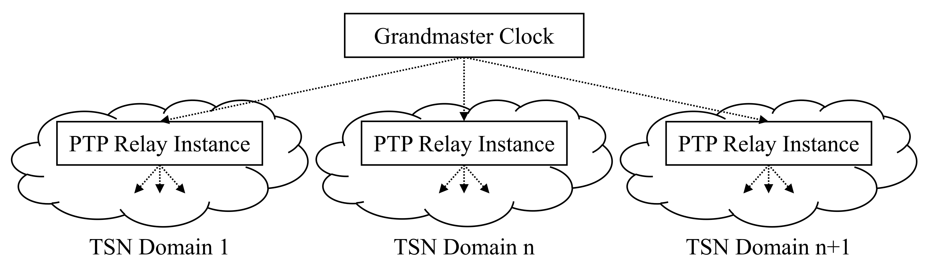
As defined in the TSN-IA Profile, for isochronous and cyclic–synchronous traffic, all network devices (TSN bridges and end-stations) are required to be synchronized to the network clock and network cycle. Timing information is exchanged in an MDTSN stream request, requiring a common time reference for the domains. Figure 6 shows an architecture for integrating time synchronization in MDTSN, implemented as a single gPTP domain. A centralized Grandmaster Clock serves time for all domains resulting in the same working clock for all participants. Steindl et al. suggested a division into sync domains [28]. Domains from different sync domains can, therefore, not communicate with isochronous or cyclic–synchronous traffic. Gutiérrez et al. evaluated the quality of time synchronization of IEEE 802.1AS in large-scale industrial automation networks [31]. They simulated different topologies using OMNeT++. Their simulation showed a precision of 1 s for time-aware systems that are 30 hops away from the Grandmaster.
6.7. Cycle Times
This approach assumes the use of identical network cycles for all TSN domains within MDTSN. The network cycle describes a repetitive time interval used in the network (e.g., opening and closing of gates of queues). Different network cycles increase the complexity of MDTSN control plane mechanisms. The application cycles, used for IO data transfer, and the application time for executing a function (e.g., control loop) are not affected. For network cycles that are multiples of each other or have fractions of a common base, the complexity is manageable. In Reference [19], a reduction ratio (RR) is specified, which defines the number of network cycles between two consecutive transmits.
6.8. Stream Request
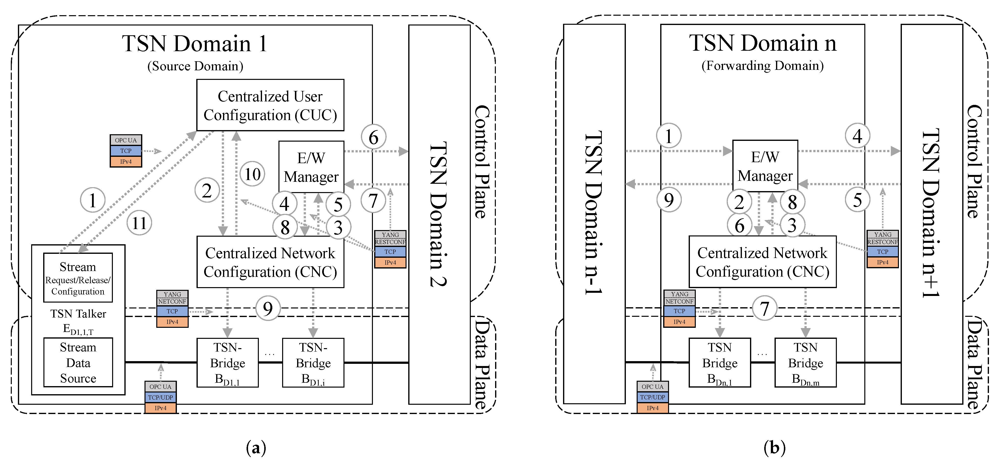
Figure 7a illustrates the procedure for the source domain of a TSN stream request in an MDTSN initiated by a talker (source domain), while showing the interaction with the first forwarding domain:
- End-to-end stream request by a talker to the CUC (using, e.g., OPC UA).
- Stream request of CUC to CNC (UNI).
- Stream request to a locally unknown destination forwarded by the CNC to the E/W Manager.
- Local stream request for the stream segment from talker to boundary network port by the E/W Manager to the CNC (UNI). New parameters: maximum latency, egress MAC address, reservation only (configuration is requested later, after successful stream negotiation).
- Local stream confirmation by the CNC to the E/W Manager (UNI). Parameters: accumulated latency (from talker to boundary network port of the next domain), transmit offset.
- Stream continuation request by the E/W Manager to neighbor E/W Manager (E/W). Adjusted parameters: ETO, LTO, maximum latency (remaining), ingress MAC address.
- Stream confirmation (or rejection) by neighboring E/W Manager to E/W Manager after all domains on the path to the listener have confirmed stream segments with requested parameters (E/W).
- Stream segment confirmation by E/W Manager to CNC (UNI). Parameters: reservation confirmation.
- Data plane configuration by CNC (e.g., NETCONF/YANG).
- Stream confirmation by CNC to CUC (UNI). Parameters: talker configuration (e.g., transmission offset).
- Talker configuration by CUC (using, e.g., OPC UA).
Figure 7b illustrates the procedure for the forwarding domain of a TSN stream request in MDTSN. It shows the interaction between the previous domain and the next domain:
- Stream continuation request by neighboring E/W Manager (E/W).
- Local stream request for the stream segment from ingress boundary network port to egress boundary network port by the E/W Manager (UNI). New parameters: maximum latency, ingress MAC address, egress MAC address, reservation only (configuration is requested later, after successful stream negotiation).
- Local stream confirmation by the CNC to the E/W Manager (UNI). Parameters: accumulated latency (from ingress boundary network port to egress boundary network port), transmit offset.
- Stream continuation request by the E/W Manager to neighbor E/W Manager (E/W). Adjusted parameters: ETO, LTO, maximum latency (remaining), ingress MAC-address.
- Stream confirmation (or rejection) by neighboring E/W Manager to E/W Manager after all domains on the path to the listener have confirmed stream segments with requested parameters (E/W).
- Stream segment confirmation by E/W Manager to CNC (UNI). Parameters: reservation confirmation.
- Data plane configuration by CNC (e.g., NETCONF/YANG).
- Stream configuration confirmation by CNC to E/W Manager (UNI).
- Stream confirmation (or rejection) to previous neighboring E/W Manager by E/W Manager (E/W).
For destination domains, the E/W Manager requests local streams with direct configuration. A prior reservation for later configuration for destination domains is not necessary as the last domain of an MDTSN stream request. The CNC also provides a listener configuration to the CUC. When multiple CUCs exist per domain, information which CUC a listener belongs to is required for the CNC. When a domain is not able to provide a stream configuration, the stream request is rejected, and previous domains are informed. The stream reservation in the CNCs is canceled.
6.9. Stream Releases
TSN streams are stateful and must be released properly. A stream release can be initiated by different entities. When the release is requested by a talker or a listener, the end-station contacts the CUC, which initiates the release at the CNC. For MDTSN, the E/W Managers must be informed when streams are released in order to notify neighboring domains. A stream release can also be initiated by problems in the network, e.g., outage of a TSN domain.
6.10. Internal Architecture of an East/Westbound Manager
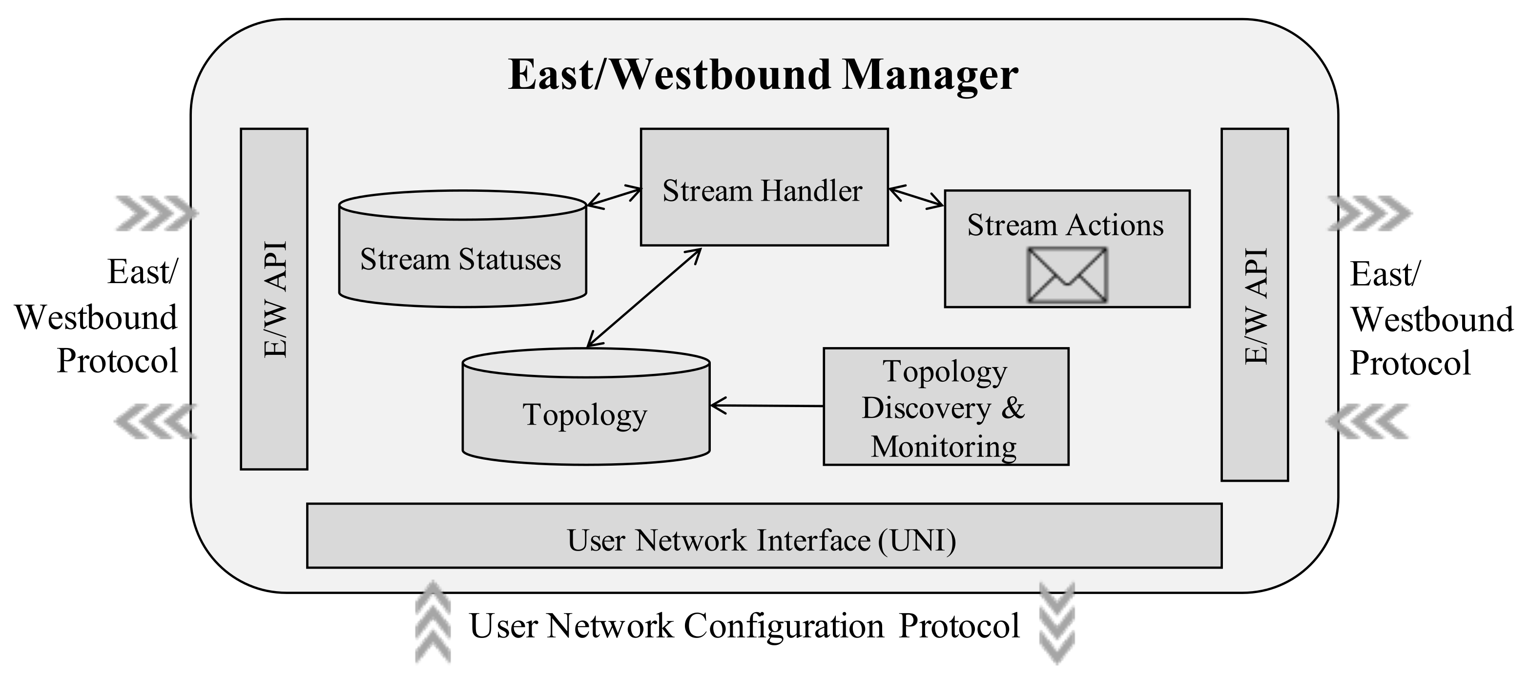
Figure 8 depicts a possible internal structure of an E/W Manager. The Stream Statuses of all multi-domain streams are tracked (e.g., established, waiting for CNC, waiting for neighbors, etc.). Furthermore, the ingress and or egress neighbor domain is stored for each stream. The Stream Handler handles the requests, releases, and failures of streams. Tasks are device lookup, path selection, border bridge selection, intra-domain stream request parameter determination, and inter-domain stream request parameter determination. The Stream Actions module sends and receives Protocol Data Units (PDU) for stream requests, releases, and failures. The Topology module stores reachability information, as presented in Section 6.1. Topology Discovery and Monitoring provides the reachability information to the Topology database. This module exchanges the reachability information for other E/W Manager using the east–westbound protocol, while monitoring other domains to, e.g., react on unavailable domains. With the User Network Interface (UNI), the E/W Manager exchanges stream requests, reservation confirmations, releases, and failures with the CNC. The east–westbound API enables the exchange of message between E/W Managers for, e.g., stream interactions, topology exchange, and domain monitoring.
7. MDTSN Data Plane Issues
This section investigates the impact of MDTSN streams on the data plane. One of the main challenges is the Inter-Domain Forwarding Offset (IDFO), in which its impact on the MDTSN end-to-end latency is investigated.
7.1. Inter-Domain Forwarding Offset
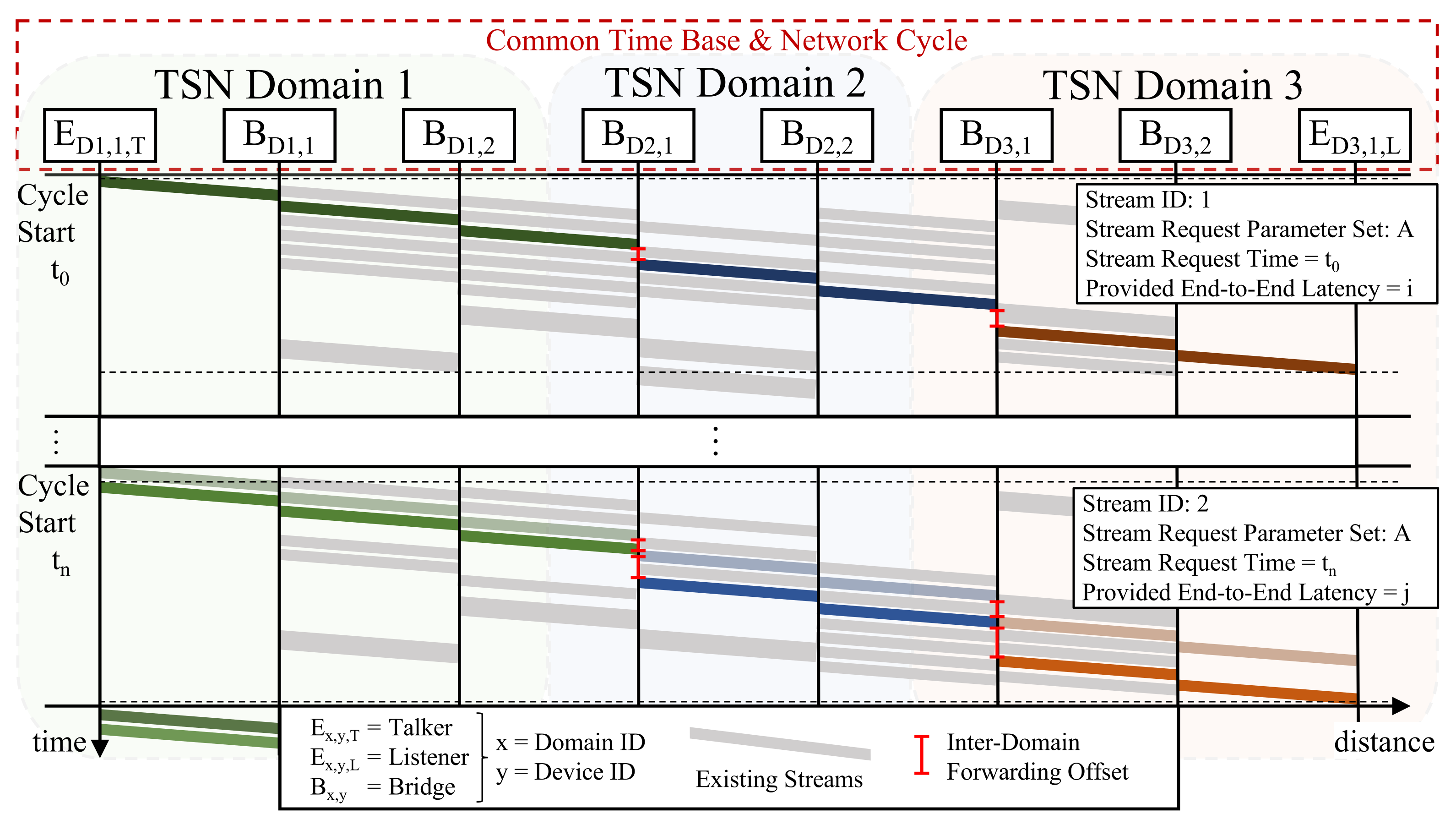
Figure 9 shows the MDTSN data plane stream configuration for identical Stream Request Parameter Sets (SRPS) at different points in time (Stream Request Time (SRT)). Between the two SRTs, other streams have been configured, while some streams have been released, i.e., the network load has changed. Even though both streams use the same SRPS, they actually achieve different end-to-end latencies. IDFOs are the main reason for different end-to-end latencies when setting up streams with identical SRPS at different times. After reserving resources for a stream, the IDFO on the data plane remains unchanged for the lifetime of this stream. Each domain is responsible for the proper scheduling of the respective segment of an end-to-end, while notifying the next domain about the exact periodic arrival time in order to continue the end-to-end stream setup. Depending on the utilization of TSN bridges in a TSN domain at the respective point in time, the IDFO may be higher or lower, resulting in a different provided end-to-end latency. In particular, when TSN domains have high traffic loads, this may even lead to unsuccessful stream requests, where the requested maximum end-to-end latency cannot be achieved.
7.2. Calculation of End-to-End Stream Latency in MDTSN
As previously described, the IDFO is a main reason for different end-to-end latencies when setting up MDTSN streams.
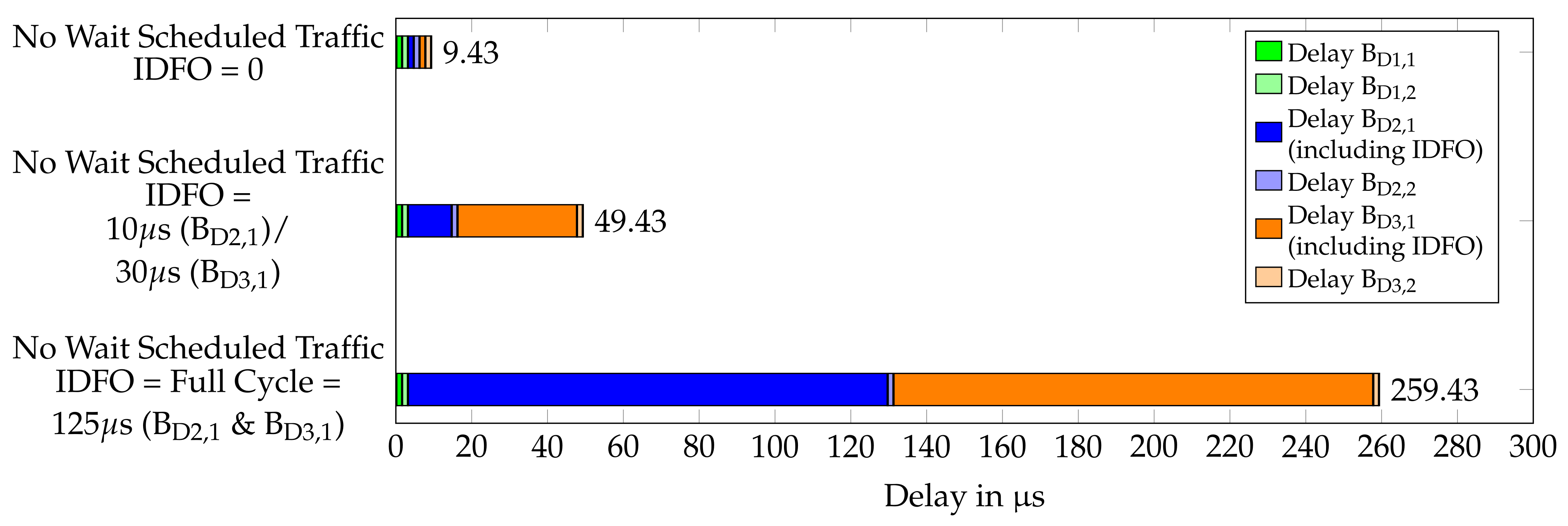
Figure 10 shows three streams with identical SRPS, but with different end-to-end latencies. The calculation is based on the architecture shown in Figure 4 with three TSN domains (n = 3). The TSN bridges run with 1 Gbit/s (Tb = time to transmit a byte) using store and forward. Streams are scheduled with no-wait scheduled traffic [32], where gates of queues are properly opened and closed to avoid queuing delay. An internal processing delay (Tp = time for internal bridge processing) of 480 ns per TSN bridge is assumed [33]. The physical medium with a distance of 50 m between devices is twisted-pair copper wire. The stream are configured with a payload of 100 bytes (including Preamble/SFD, Header, Payload, FCS) (Nb = number of bytes), a cycle time of 125 s and 1 frame per cycle. This results in an optimal bridge delay of 1.28 s and a physical propagation delay of 0.25 s for each link. The end-to-end latency is measured between the reference plane of the talker and the listener, as introduced in Section 2.4. Each stream has different IDFOs considered as part of the latency of the ingress bridge. While the first stream has an optimal end-to-end latency of 9.43 s, the second stream has an end-to-end latency of 49.43 s due to a sum of 40 s IDFOs. The last stream shows a configuration where each IDFO has the size of a full cycle length, i.e., 125 s. The end-to-end latency here is 259.43 s. Depending on the requested maximum latency, this stream configuration may have been unsuccessful.
The size of the IDFO is not limited, and it may have the size of multiple network cycles. For cyclic–synchronous traffic, where the end-to-end latency is a multiple of the network cycle, a large IDFO may work. For isochronous traffic, where the end-to-end latency is shorter than the network cycle, large IDFOs lead to unsuccessful stream requests.
8. Proof of Concept Implementation
In order to prove the viability of the presented concept for MDTSN control plane mechanisms, a PoC has been implemented. As a basis for this PoC, operational single TSN domains, including TSN bridges and end-stations on the data plane, as well as CUC and CNC as part of the control plane, are needed.
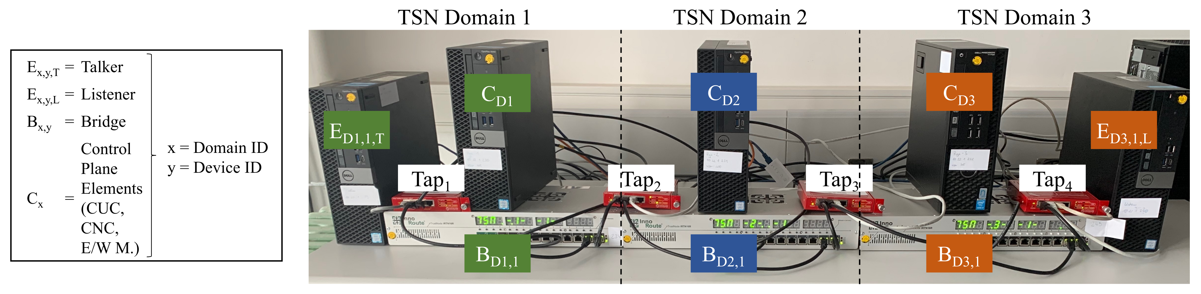
Figure 11 gives a photo of the PoC implementation, similar to the architecture of Figure 4. For the evaluation of MDTSN control plane mechanisms developed, each domain needs an ingress network port and an egress network port on the data plane. Therefore, a single TSN bridge per domain is sufficient. Operational implementations of CUCs and CNCs are currently not available on the market. The technical basis had to be implemented as further described.
8.1. Technical Basis for Evaluation of MDTSN Concept
The implementation of the technical basis for the evaluation of the MDTSN concept partly implements the following standards:
- IEEE 802.1AS for time-synchronization;
- IEEE 802.1Qbv for scheduled traffic;
- IEEE 802.1Qcc for dynamic stream configuration.
For the data plane, TSN bridges (“TrustNodes”) of the vendor InnoRoute are chosen because they support the required standards. The TSN bridges use the open source PTP implementation ptp4l for time synchronization. The chosen TSN bridges have a mechanism to support synchronization of cycle starting times (called basetime in Reference [34]).
For measurements on the data plane, in order to validate the configurations applied from the control plane, network taps (Datacom CTP-1000) mirror the traffic between the links on the data plane. A measurement system using a 4-port network card (Napatech NT40A01 SmartNIC) with hardware acceleration for high-accuracy time stamping is used.
For the control plane, the open-source SDN controller Ryu [35], written in Python, has been extended with a Ryu application to add functionality of the CUC and the CNC.
8.1.1. CNC Implementation
The PoC implementation of the CNC supports the reservation and configuration of unidirectional TSN streams. Each stream is configured with exclusive gating, i.e., each stream is assigned to its own queue. The CNC implementation supports stream reservations to a granularity of 1 s. The ETO and LTO are defined in s of the network cycle. The network cycle length can be set at the start of the CNC (e.g., 125 s).
Depending on the number of frames and the frame size, the size of the reservation is calculated (minimum 1 s). The bridge delay and the propagation delay are also required for the schedule calculation. Bridge delays are specified for each network port pair combination. The time a frame takes to pass through the bridge’s relay has to be determined. Furthermore, the propagation delay between an egress network port and the next ingress network port has to be defined. The determination of these delays is not part of this work. The values are agnostic to the east–westbound protocol. Using the calculated optimal bridge delay of 1.28 s and propagation delay of 0.25 s, as presented in Section 7.2, a delay of 2 s between two devices has been set. The schedule calculation uses first free subsequent time slot (s) that fit into the schedule and satisfy the time-aware stream request parameters.
A GCL is generated as a YANG configuration file in XML format for TSN bridges and configured using Netconf. The OpenFlow protocol is used to match traffic to queues by the source and destination MAC address of the streams. YANG configurations for end-stations are provided to the CUC.
8.1.2. CUC Implementation
The interface of the CUC for stream requests and releases by end-stations is implemented as a REST API using the Python-based micro web framework flask. The messages are encoded using JSON. End-stations network configurations are provided by the CNC and are configured by the CUC using Netconf and OpenFlow protocol. The communication between the CUC and the CNC (UNI) is implemented using the Python API.
8.2. East/Westbound Implementation
The PoC implementation of the E/W Manager, implemented as a Ryu-application, supports stream requests and releases. The communication between E/W Managers is implemented as a REST API using JSON encoding. The communication between the E/W Manager and the CNC (UNI) uses the provided Python API of the CNC. An automatic topology exchange and domain monitoring has not been implemented because it is not relevant for evaluation of the stream setup mechanisms. For this PoC implementation, topology information is set manually. This includes a list of local devices, remote devices, and their domains, directly and indirectly connected domains, and their boundary network ports, as well as contact information for the other domain’s E/W Manager.
9. Evaluation
In order to make the evaluation better understandable, stream request scenarios are presented in detail in Section 9.1. In Section 9.2, control plane mechanisms are evaluated, considering different aspects.
9.1. MDTSN Stream Request Scenarios
Streams with different stream parameters have been requested to achieve a broad test coverage for different kinds of scenarios. Selected stream requests to illustrate specific aspects for the evaluation in Section 9.2 are given in Table 1.
Table 1 shows a list of unidirectional stream requests and their communication parameters, which have been consecutively requested and configured within the MDTSN test environment. The streams are requested from different source domains. The listener remains unchanged for all stream requests. The requested streams with ID4 and ID7 have failed during the stream setup process.
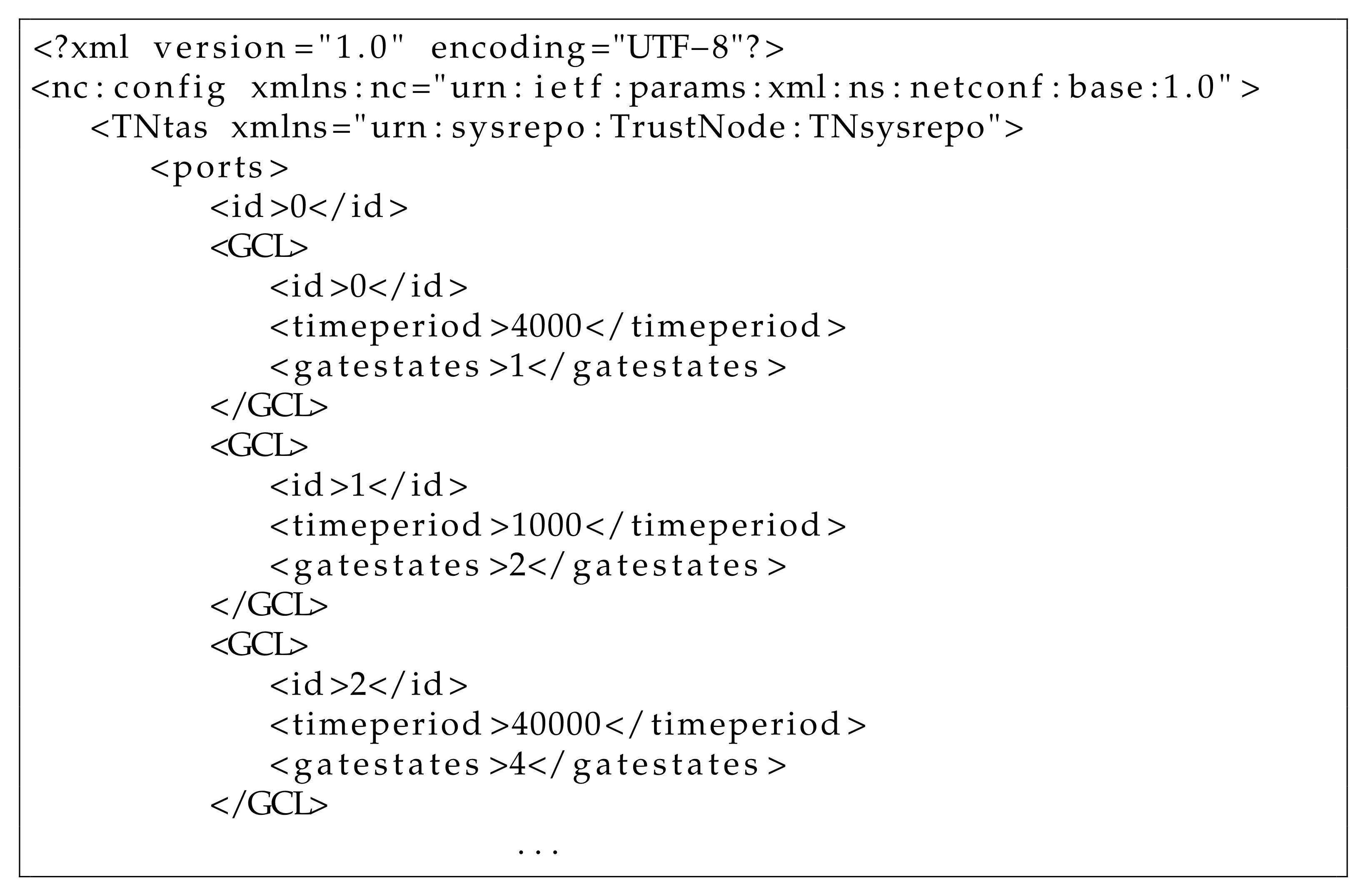
In order to illustrate implementation and operation of the PoC, as explained in Section 8, Figure 12 shows a part of the GCL as a YANG configuration model encoded in XML. The GCL is generated by the CNC of TSN domain 2 as initiated by the E/W Manager of the respective domain, as a consequence of the stream requests given in Table 1. It is applied by the CNC to TSN bridge BD2,1 of this domain using the Netconf protocol. The effect of this configuration on the data plane can be seen in Figure 13b in the beginning of line BD2,1.
The configuration as illustrated in Figure 12 is separated by the TSN bridges’ network ports. Each port has a list of GCL entries, which includes an ID, a time period (in ns) to open gates and gatestate value which specify gates to be opened, e.g., the second entry with an ID of 1 opens the gate of queue 1 (Binary 00000010 = Decimal 2) for 1 s.
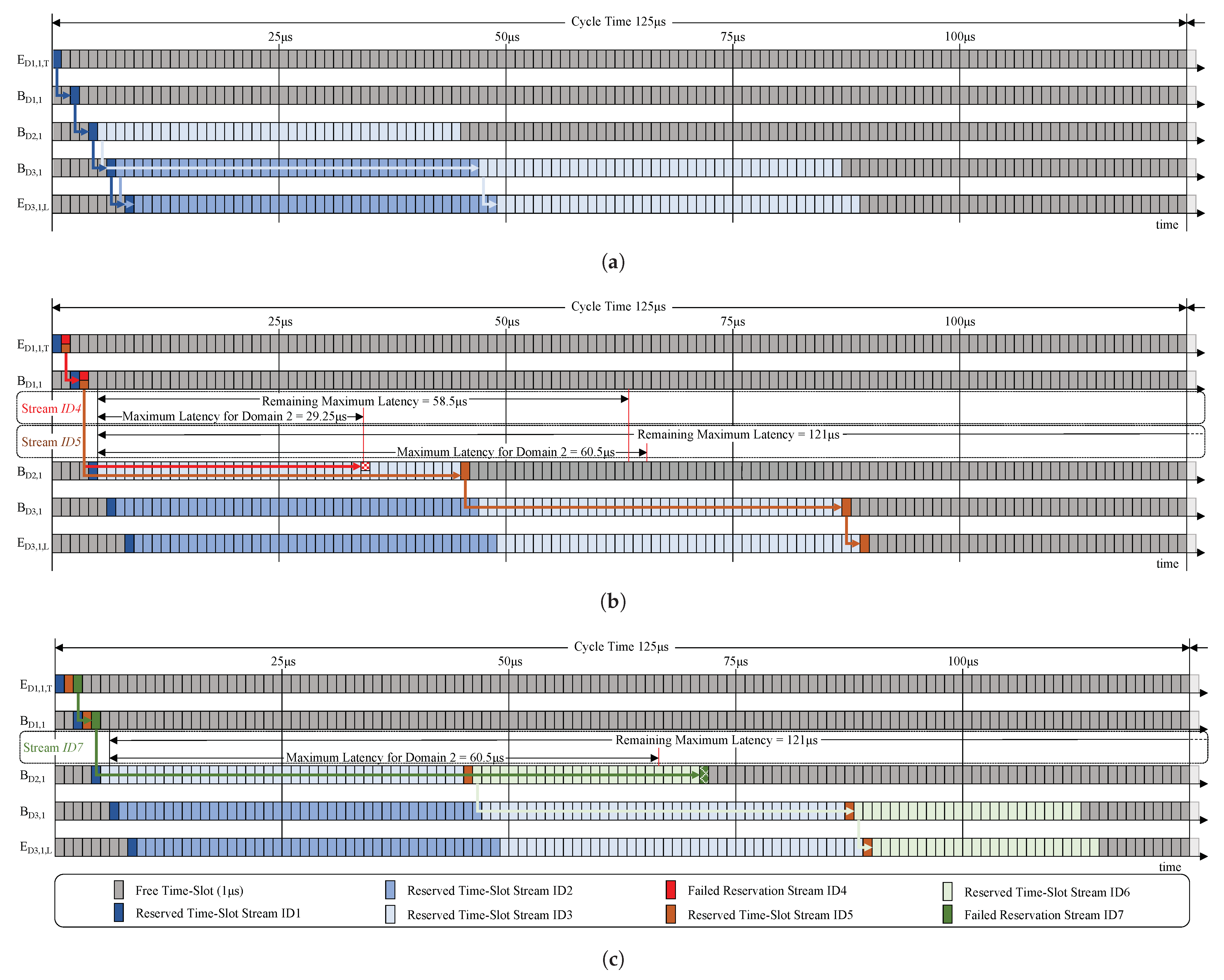
Figure 13 shows one TSN network cycle on the data plane when the configuration of stream requests as given in Table 1 are processed step by step.
Figure 13a shows the configured and operational streams after successful stream requests for streams ID1, ID2, and ID3. While stream ID1 is assigned a single time slot of 1 s, stream requests ID2 (domain 3 internal) and ID3 (domain 2 to domain 3) each resulted in the reservation of a time slot with the length of 40 s.
Figure 13b provides a more detailed view on the process of stream requests for streams ID4 and ID5. The stream request with ID4 has failed during the configuration process. It has been requested with a maximum latency of 62.5 s. Frames would arrive at BD2,1 after a total of 4 s, leaving a remaining maximum latency of 58.5 s. Due to the latency sharing mechanism, domain 2 is requested a maximum latency of 29.25 s. The resources needed to fulfill this request are already assigned for streams ID1 and ID3, and the request process is rejected. However, without the chosen sharing mechanism, the stream request would have been rejected later by domain 3. Thus, the load on the control plane is reduced. Stream ID5, with a requested maximum latency of 125 s, is successfully configured.
Figure 13c shows the newly configured and operational stream ID6. Stream request ID7, with a requested maximum latency of 125 s, failed during the stream configuration in domain 2, due to the maximum latency given by the latency sharing mechanism.
9.2. Concept Evaluation
The integration of east–westbound communication into MDTSN has been achieved using the presented control plane mechanisms. End-to-end MDTSN streams with bounded latency requirements are set up and released successfully. This has been shown with a large set of representative stream setups. A selected subset is given in Section 9.1.
The presented concept is based on existing TSN standards, particularly IEEE 802.1Qcc. The IDFO is considered on the ingress side of forwarding domains by setting identical values for ETO and LTO, i.e., reusing the standardized stream request mechanisms between talker and single domain control plane. An important advantage of the control plane mechanisms developed is that converting these mechanisms into standards would require additions to existing standards or additional standards but not a single modification of the existing standards.
A further advantage is that bounded-latency end-to-end streams in multi-domain scenarios can be set up, without disclosing the internal topology of TSN domains to other connected TSN domains, i.e., topology hiding is achieved.
The heuristic per domain sharing mechanism for the requested end-to-end maximum latency of a stream requested, as presented in Section 6.3, has significant advantages. The calculation and interaction complexity on the control plane is comparably simple, and, besides the maximum end-to-end latency, only the number of domains on the path is required as input. Moreover, the mechanism fits to the peer-to-peer cooperation between E/W Managers in the horizontal architecture chosen for the MDTSN control plane.
However, in case of high traffic loads in data planes of domains on the path of an end-to-end stream, MDTSN stream requests may be rejected, although a more complex sharing mechanism could successfully set up an end-to-end stream. A more complex sharing mechanism would iteratively request CNCs of the domains on the path to reduce achieved latencies per domain so as to redistribute the shares of the maximum end-to-end latency. The calculation effort for the CNC of a domain significantly increases when the absolute minimum possible end-to-end latency is to be determined, compared to only fulfilling a defined maximum bounded latency [16]. Therefore, CNCs will typically schedule streams so as to fulfill the maximum requested latency for their domain but not necessarily deliver the minimum possible latency on that segment. With respect to this tradeoff between the overall control plane computational effort for an end-to-end stream as opposed to reducing the probability of rejecting MDTSN stream requests, the heuristic approach proposed by us delivers a reasonable compromise.
10. Conclusions and Future Work
Inter-domain communication in TSN has been identified to be required for various use-cases. On-demand end-to-end bounded-latency stream reservation and configuration in MDTSN has been achieved. Control plane mechanisms for the integration of an east–westbound protocol in the standardized TSN control plane for single domains (fully centralized model [4]) are developed, implemented in a PoC, and evaluated in an MDTSN test environment. Results show the viability of the concept. The MDTSN control plane concept presented has significant advantages. It can be implemented without modifying existing TSN standards, considers topology hiding, and applies an efficient mechanism for sharing the maximum end-to-end latency between domains on the path.
There are a number of aspects that should be addressed in future work. MDTSN control plane mechanisms can be extended to support, e.g., differing network cycles of TSN domains on the data plane and multi-cast streams, as well as Frame Replication and Elimination for Reliability (FRER) [36]. Topology hiding provided by the MDTSN concept presented here improves security. However, further security consideration are recommendable. For use cases with frequent setting up and release of MDTSN streams, control plane performance should be analyzed.
Author Contributions
Conceptualization, M.B.; Funding acquisition, D.W.; Investigation, M.B. and D.W.; Methodology, M.B.; Project administration, D.W.; Resources, M.B.; Software, M.B.; Supervision, D.W.; Validation, M.B.; Visualization, M.B.; Writing—original draft, M.B.; Writing—review & editing, M.B. and D.W. All authors have read and agreed to the published version of the manuscript.
Funding
This work was funded by the Federal Ministry for Education and Research within the KMU-innovativ program as a part of MONAT (16KIS0782) and the Ministry for Science and Culture of Lower Saxony as a part of the research project SecuRIn (VWZN3224).
Conflicts of Interest
The authors declare no conflict of interest.
Abbreviations
The following abbreviations are used in this manuscript:
| TSN | Time-Sensitive Networks |
| MDTSN | Multi-Domain Time-Sensitive Networks |
| TSN-IA Profile | TSN Profile for Industrial Automation |
| IDFO | Inter-Domain Forwarding Offset |
| SRP | Stream Reservation Protocol |
| GCL | Gate Control List |
| TC | Traffic Class |
| ETO | Earliest Transmit Offset |
| LTO | Latest Transmit Offset |
| FPI | Frames Per Interval |
| MaaS | Manufacturing as a Service |
| PTP | Precision Time Protocol |
| gPTP | generalized Precision Time Protocol |
| PoC | Proof of Concept |
| PDU | Protocol Data Unit |
References
- Bello, L.L.; Steiner, W. A perspective on IEEE time-sensitive networking for industrial communication and automation systems. Proc. IEEE 2019, 107, 1094–1120. [Google Scholar] [CrossRef]
- IEEE 802.1 Working Group. IEC/IEEE 60802 TSN Profile for Industrial Automation. Available online: https://1.ieee802.org/tsn/iec-ieee-60802/ (accessed on 13 July 2021).
- Wollschlaeger, M.; Sauter, T.; Jasperneite, J. The future of industrial communication: Automation networks in the era of the internet of things and industry 4.0. IEEE Ind. Electron. Mag. 2017, 11, 17–27. [Google Scholar] [CrossRef]
- IEEE Standard for Local and Metropolitan Area Networks—Bridges and Bridged Networks—Amendment 31: Stream Reservation Protocol (SRP) Enhancements and Performance Improvements; IEEE Std 802.1Qcc-2018 (Amendment to IEEE Std 802.1Q-2018 as Amended by IEEE Std 802.1Qcp-2018); IEEE: Piscataway, NJ, USA, 2018; pp. 1–208. [CrossRef]
- Haleplidis, E.; Pentikousis, K.; Denazis, S.; Salim, J.H.; Meyer, D.; Koufopavlou, O. Software-Defined Networking (SDN): Layers and Architecture Terminology. RFC 2015, 7426, 1–35. [Google Scholar]
- Schriegel, S.; Kobzan, T.; Jasperneite, J. Investigation on a distributed SDN control plane architecture for heterogeneous time sensitive networks. In Proceedings of the 14th IEEE International Workshop on Factory Communication Systems (WFCS), Imperia, Italy, 13–15 June 2018; pp. 1–10. [Google Scholar] [CrossRef]
- Böhm, M.; Ohms, J.; Wermser, D. Multi-Domain Time-Sensitive Networks-An East-Westbound Protocol for Dynamic TSN-Stream Configuration Across Domains. In Proceedings of the 2019 24th IEEE International Conference on Emerging Technologies and Factory Automation (ETFA), Zaragoza, Spain, 10–13 September 2019; pp. 1363–1366. [Google Scholar] [CrossRef]
- IEEE Standard for Local and Metropolitan Area Networks—Bridges and Bridged Networks—Amendment 25: Enhancements for Scheduled Traffic; IEEE Std 802.1Qbv-2015; IEEE: Piscataway, NJ, USA, 2016; pp. 1–57. [CrossRef]
- IEEE Standard for Local and Metropolitan Area Networks—Timing and Synchronization for Time-Sensitive Applications; IEEE 802.1AS-2020; IEEE: Piscataway, NJ, USA, 2020; pp. 1–421. [CrossRef]
- IEEE Standard Profile for Use of IEEE 1588 Precision Time Protocol in Power System Applications; IEEE Std C37.238-2017 (Revision of IEEE Std C37.238-2011); IEEE: Piscataway, NJ, USA, 2017; pp. 1–42. [CrossRef]
- Bridges and Bridges Networks—Amendment: Configuration Enhancements for Time-Sensitive Networking; IEEE P802.1Qdj/D.01; IEEE: Piscataway, NJ, USA, 2020; pp. 1–30.
- OPC Foundation. OPC Unified Architecture Specification, Part 14: Pubsub, Draft 1.04.21 2017. Available online: https://opcfoundation.org/developer-tools/specifications-unified-architecture/part-14-pubsub/ (accessed on 15 July 2021).
- Bruckner, D.; Blair, R.; Stanica, M.; Ademaj, A.; Skeffington, W.; Kutscher, D.; Schriegel, S.; Wilmes, R.; Wachswender, K.; Leurs, L.; et al. OPC UA TSN—A New Solution for Industrial Communication. Available online: https://cdn.weka-fachmedien.de/whitepaper/files/OPC_UA_TSN_-_A_new_Solution_for_Industrial_Communication.pdf (accessed on 15 July 2021).
- Craciunas, S.S.; Oliver, R.S.; Chmelík, M.; Steiner, W. Scheduling real-time communication in IEEE 802.1 Qbv time sensitive networks. In Proceedings of the 24th International Conference on Real-Time Networks and Systems, Brest, France, 19–21 October 2016; pp. 183–192. [Google Scholar] [CrossRef]
- Gavriluţ, V.; Pop, P. Scheduling in time sensitive networks (TSN) for mixed-criticality industrial applications. In Proceedings of the 2018 14th IEEE International Workshop on Factory Communication Systems (WFCS), Imperia, Italy, 13–15 June 2018; pp. 1–4. [Google Scholar] [CrossRef]
- Li, Q.; Li, D.; Jin, X.; Wang, Q.; Zeng, P. A simple and efficient time-sensitive networking traffic scheduling method for industrial scenarios. Electronics 2020, 9, 2131. [Google Scholar] [CrossRef]
- Industrial Internet Consortium (IIC). Time Sensitive Networks for Flexible Manufacturing Testbed Characterization and Mapping of Converged Traffic Types. Available online: https://iiconsortium.org/pdf/IIC_TSN_Testbed_Char_Mapping_of_Converged_Traffic_Types_Whitepaper_20180328.pdf (accessed on 13 July 2021).
- Bruckner, D.; Stănică, M.P.; Blair, R.; Schriegel, S.; Kehrer, S.; Seewald, M.; Sauter, T. An introduction to OPC UA TSN for industrial communication systems. Proc. IEEE 2019, 107, 1121–1131. [Google Scholar] [CrossRef]
- IEC CD/IEEE 802.1 TSN TG Ballot. Use Cases IEC/IEEE 60802. Available online: https://www.ieee802.org/1/files/public/docs2018/60802-industrial-use-cases-0918-v13.pdf (accessed on 2 July 2021).
- KUKA Systems GmbH. Hello Industry 4.0. Available online: https://www.kuka.com/en-de/future-production/industrie-4-0 (accessed on 11 June 2021).
- AutomationML e.V. Magdeburg. AutomationML. Available online: https://www.automationml.org/ (accessed on 20 July 2021).
- Yin, H.; Xie, H.; Tsou, T.; Lopez, D.; Aranda, P.; Sidi, R. Sdni: A Message Exchange Protocol for Software Defined Networks (SDNS) Across Multiple Domains; IETF: Fremont, CA, USA, 2012. [Google Scholar]
- Kreutz, D.; Ramos, F.M.; Verissimo, P.E.; Rothenberg, C.E.; Azodolmolky, S.; Uhlig, S. Software-defined networking: A comprehensive survey. Proc. IEEE 2014, 103, 14–76. [Google Scholar] [CrossRef] [Green Version]
- Zhang, Y.; Cui, L.; Wang, W.; Zhang, Y. A survey on software defined networking with multiple controllers. J. Netw. Comput. Appl. 2018, 103, 101–118. [Google Scholar] [CrossRef]
- Phemius, K.; Bouet, M.; Leguay, J. Disco: Distributed multi-domain sdn controllers. In Proceedings of the 2014 IEEE Network Operations and Management Symposium (NOMS), Krakow, Poland, 5–9 May 2014; pp. 1–4. [Google Scholar] [CrossRef] [Green Version]
- Bagci, K.T.; Yilmaz, S.; Sahin, K.E.; Tekalp, A.M. Dynamic end-to-end service-level negotiation over multi-domain software defined networks. In Proceedings of the 2016 IEEE Sixth International Conference on Communications and Electronics (ICCE), Ha-Long, Vietnam, 27–29 July 2016; pp. 33–39. [Google Scholar] [CrossRef]
- Chen, L. TSN Configuration Interaction. Available online: https://www.ieee802.org/1/files/public/docs2019/new-chen-TSN-Configuration-Interaction-0719-v01.pdf (accessed on 26 July 2021).
- Steindl, G. Inter TSN Domain Communication Concept. Available online: https://www.ieee802.org/1/files/public/docs2020/60802-Steindl-et-al-InterTsnDomainCommunication-0620-v3.pdf (accessed on 26 July 2021).
- Huang, Y.; Ge, H.; Lee, J.; Dai, Y.; Xu, D.; Zhang, J.; Gao, Q.; Zhao, S. Cluster-Head and Border-Node Based Cluster Routing Protocol for LR-WPAN. In Proceedings of the 2016 IEEE 30th International Conference on Advanced Information Networking and Applications (AINA), Crans-Montana, Switzerland, 23–25 March 2016; pp. 132–139. [Google Scholar]
- IEEE Standard for Local and Metropolitan area Networks—Audio Video Bridging (AVB) Systems; IEEE Std 802.1BA-2011; IEEE: Piscataway, NJ, USA, 2011; pp. 1–45. [CrossRef]
- Gutiérrez, M.; Steiner, W.; Dobrin, R.; Punnekkat, S. Synchronization quality of IEEE 802.1 AS in large-scale industrial automation networks. In Proceedings of the 2017 IEEE Real-Time and Embedded Technology and Applications Symposium (RTAS), Pittsburgh, PA, USA, 18–21 April 2017; pp. 273–282. [Google Scholar] [CrossRef]
- Dürr, F.; Nayak, N.G. No-wait packet scheduling for IEEE time-sensitive networks (TSN). In Proceedings of the 24th International Conference on Real-Time Networks and Systems, Brest, France, 19–21 October 2016; pp. 203–212. [Google Scholar] [CrossRef]
- Woods, J. Cut-Through Considerations and Impacts to Industrial Networks. Available online: https://www.ieee802.org/1/files/public/docs2017/new-woods-cutthroughconsiderations-0518-v01.pdf (accessed on 23 July 2021).
- IEEE Standard for Local and Metropolitan Area Network–Bridges and Bridged Networks; IEEE Std 802.1Q-2018 (Revision of IEEE Std 802.1Q-2014); IEEE: Piscataway, NJ, USA, 2018; pp. 1–1993. [CrossRef]
- Community, R.S.F. Ryu SDN Framework. Available online: https://ryu-sdn.org/ (accessed on 4 August 2021).
- IEEE Standard for Local and Metropolitan Area Networks—Frame Replication and Elimination for Reliability; IEEE Std 802.1CB-2017; IEEE: Piscataway, NJ, USA, 2017; pp. 1–102. [CrossRef]
Figure 1.
Architectural models presented in IEEE 802.1Qcc for single Time Sensitive Networking (TSN) domains [4]. (a) Time Sensitive Networking (TSN) in the fully distributed model; (b) TSN with centralized network/distributed model; (c) TSN in the fully centralized model.
Figure 1.
Architectural models presented in IEEE 802.1Qcc for single Time Sensitive Networking (TSN) domains [4]. (a) Time Sensitive Networking (TSN) in the fully distributed model; (b) TSN with centralized network/distributed model; (c) TSN in the fully centralized model.

Figure 2.
Time-sensitive stream request procedure in the fully centralized model, as described in IEEE 802.1Qcc [4].
Figure 2.
Time-sensitive stream request procedure in the fully centralized model, as described in IEEE 802.1Qcc [4].

Figure 3.
Interaction of Manufacturing as a Service (MaaS) providers with cooperating robots in interconnected TSN domains.
Figure 3.
Interaction of Manufacturing as a Service (MaaS) providers with cooperating robots in interconnected TSN domains.

Figure 4.
East–westbound control plane communication in multi-domain time-sensitive networks (MDTSN).
Figure 4.
East–westbound control plane communication in multi-domain time-sensitive networks (MDTSN).

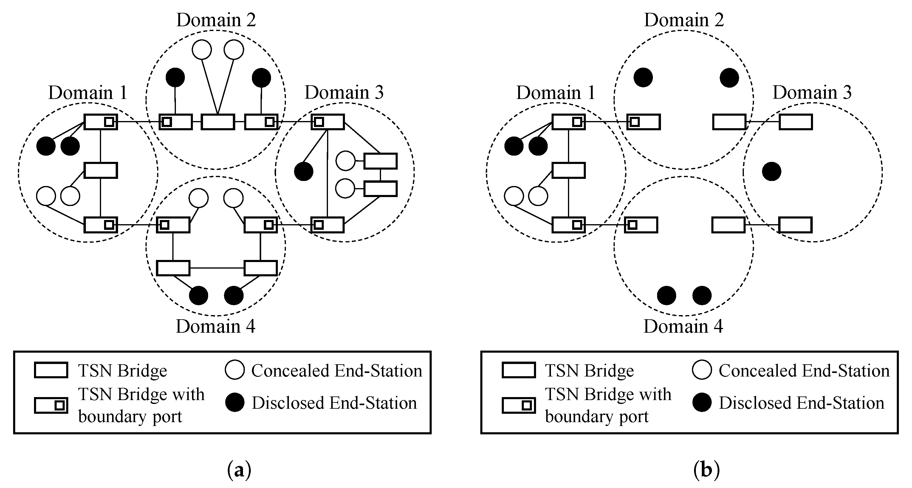
Figure 5.
Visibility of the data plane topology to the control plane in MDTSN, topology hiding. (a) Entire data plane topology; (b) Partially hided data plane topology as visible for E/W Manager of domain 1
Figure 5.
Visibility of the data plane topology to the control plane in MDTSN, topology hiding. (a) Entire data plane topology; (b) Partially hided data plane topology as visible for E/W Manager of domain 1

Figure 6.
MDTSN in a single generalized precision time protocol (gPTP) domain.

Figure 7.
MDTSN stream request procedure (for explanation of indices Figure 4). (a) MDTSN stream request—source domain; (b) MDTSN stream request—forwarding domain.
Figure 7.
MDTSN stream request procedure (for explanation of indices Figure 4). (a) MDTSN stream request—source domain; (b) MDTSN stream request—forwarding domain.

Figure 8.
East/westbound manager in the MDTSN control plane.

Figure 9.
Data plane configuration for two MDTSN streams setups with identical Stream Request Parameter Sets (SRPSs) at different times, i.e., different existing traffic loads; scenario with three TSN domains.
Figure 9.
Data plane configuration for two MDTSN streams setups with identical Stream Request Parameter Sets (SRPSs) at different times, i.e., different existing traffic loads; scenario with three TSN domains.

Figure 10.
Comparison of three MDTSN stream end-to-end latencies with identical Stream Request Parameter Sets requested at different times. Calculations are based on three TSN domains, 1 Gbit/s TSN-Bridges using store and forward, 480 ns internal processing delay [33], cyclic traffic with a PDU of 100 bytes (including preamble), and cycle time of 125 s, 50 m copper wire links. (For explanation of indices Figure 4).

Figure 11.
MDTSN test environment.

Figure 12.
YANG data model of the gate control list for BridgeD2,1 (XML encoded) after requesting and configuring streams, as shown in Table 1.
Figure 12.
YANG data model of the gate control list for BridgeD2,1 (XML encoded) after requesting and configuring streams, as shown in Table 1.

Figure 13.
Example stream configurations generated by the MDTSN control plane of the PoC implementation for stream requests shown in Table 1 (smallest time slot size for streams is 1 μs; network cycle is 125 μs). (a) Operational streams after successful stream requests ID1, ID2, and ID3 (Table 1); (b) Illustration of unsuccessful stream request ID4; operational stream after successful stream request ID5 (Table 1); (c) Operational stream after successful stream request ID6; illustration of unsuccessful stream request ID7 (Table 1).


Table 1.
Example stream requests.
| Stream Data Frame Specification | Stream Time Aware Specification | Stream Request Result | ||||||||||
|---|---|---|---|---|---|---|---|---|---|---|---|---|
| Stream- ID | Src- Addr. | Src- Dom. | Dst- Addr. | Dst- Dom. | Cycle | Frame Size | FPI | ETO | LTO | Max. Lat. | Status | Prov. E2E Lat. |
| ID1 | ::01:10 | 1 | ::03:10 | 3 | 125 s | 100 B | 1 | 0 s | 125 s | 125 s | 🗸 | 8 s |
| ID2 | ::03:10 | 3 | ::03:10 | 3 | 125 s | 100 B | 50 | 0 s | 125 s | 125 s | 🗸 | 4 s |
| ID3 | ::02:10 | 2 | ::03:10 | 3 | 125 s | 100 B | 50 | 0 s | 125 s | 125 s | 🗸 | 6 s |
| ID4 | ::01:10 | 1 | ::03:10 | 3 | 125 s | 100 B | 1 | 0 s | 125 s | 65.5 s | ✗ | ✗ |
| ID5 | ::01:10 | 1 | ::03:10 | 3 | 125 s | 100 B | 1 | 0 s | 125 s | 125 s | 🗸 | 88 s |
| ID6 | ::02:10 | 2 | ::03:10 | 3 | 125 s | 100 B | 25 | 0 s | 125 s | 125 s | 🗸 | 46 s |
| ID7 | ::01:10 | 1 | ::03:10 | 3 | 125 s | 100 B | 1 | 0 s | 125 s | 125 s | ✗ | ✗ |
Publisher’s Note: MDPI stays neutral with regard to jurisdictional claims in published maps and institutional affiliations. |
© 2021 by the authors. Licensee MDPI, Basel, Switzerland. This article is an open access article distributed under the terms and conditions of the Creative Commons Attribution (CC BY) license (https://creativecommons.org/licenses/by/4.0/).
Share and Cite
MDPI and ACS Style
Böhm, M.; Wermser, D. Multi-Domain Time-Sensitive Networks—Control Plane Mechanisms for Dynamic Inter-Domain Stream Configuration. Electronics 2021, 10, 2477. https://doi.org/10.3390/electronics10202477
AMA Style
Böhm M, Wermser D. Multi-Domain Time-Sensitive Networks—Control Plane Mechanisms for Dynamic Inter-Domain Stream Configuration. Electronics. 2021; 10(20):2477. https://doi.org/10.3390/electronics10202477
Chicago/Turabian StyleBöhm, Martin, and Diederich Wermser. 2021. "Multi-Domain Time-Sensitive Networks—Control Plane Mechanisms for Dynamic Inter-Domain Stream Configuration" Electronics 10, no. 20: 2477. https://doi.org/10.3390/electronics10202477
Note that from the first issue of 2016, this journal uses article numbers instead of page numbers. See further details here.