Article

Generator Design Considering Mover Action to Improve Energy Conversion Efficiency in a Free-Piston Engine Generator

1
Faculty of Engineering, Shinshu University, Nagano 380-8553, Japan
2
College of Engineering, Kanazawa Institute of Technology, Nonoichi 921-8501, Japan
*
Author to whom correspondence should be addressed.
Electronics 2021, 10(17), 2142; https://doi.org/10.3390/electronics10172142
Submission received: 3 August 2021 / Revised: 27 August 2021 / Accepted: 31 August 2021 / Published: 3 September 2021

Abstract

:
In a free-piston engine generator (FPEG), the power of the engine can be directly regenerated by linear generators without a crank. The mover motion of this system is interrelated with engine and power generation efficiencies due to the direct connection between the mover of the generator and the piston of the engine. The generator should be designed to improve the overall energy conversion efficiency. The dimensions and mass of the mover limit its operating stroke and drive frequency. Herein, we propose a method for designing linear generators and constructing FPEG systems, considering the mover operation to improve engine efficiency. We evaluated the effect of mover operation on the engine and generation efficiencies using thermal and electromagnetic field analysis software. The proposed design method improves the overall energy conversion efficiency compared with a generator that considers only the maximization of generation efficiency. Setting the mover operation for higher engine efficiency and designing a linear generator to realize the operation can effectively improve the energy conversion efficiency of FPEGs.

1. Introduction

Linear generators that directly convert energy without a linear motion conversion mechanism are used for ocean and vibration power generation [1,2,3,4,5]. The input energy of the systems has a random waveform with nonconstant cycles and amplitudes. The design and control of linear generators considering the characteristics of ocean power generation and vibration power generation have been proposed [6,7,8,9].
A free-piston engine generation system (FPEG) recovers the combustion energy of the engine with a linear generator [10,11,12,13,14,15,16]. This system requires a highly efficient linear generator design, considering that almost the same combustion energy not randomly but repeatedly acts on the generator. High efficiency is achieved using a linear generator that uses permanent magnets with a Halbach structure [17,18]. A cylindrical linear generator has been designed for the free piston, and the output density has been improved for automobiles [19,20,21,22].
FPEG is a power generation system without the crank mechanism, meaning the piston of the engine and the mover of the linear generator are connected. The operation of the piston (movable element) is adjusted using a power generation control with the inverter [23,24]. Setting the proper mover motion improves the thermal efficiency of the engine and the power generation efficiency of the linear generator. Delaying piston operation immediately after combustion can improve the engine thermal efficiency of the engine [25]. Extending the stroke with a single engine type using a spring suppresses the maximum braking force of the linear generator and reduces copper loss [15]. To maximize the energy conversion efficiencies of FPEGs, minimizing the engine and generator losses, the relevance of motor movement, engine efficiency, and generator efficiency need to be considered.
A design that considers only the high efficiency of the linear generator limits the operating range of the mover, making it difficult to improve the thermal efficiency of the engine. In particular, improving engine efficiency by ~40% more effectively improves the energy conversion efficiency than improving the power generation efficiency by 90%. To design a linear generator, a mover operation that can improve engine efficiency needs to be considered. Herein, we propose a procedure for constructing a system with high energy conversion efficiency, which considers all engine specifications, the setting of the mover motion history, and the design of the linear generator.
This paper mainly proposes a method for designing linear generators and constructing systems considering a mover operation that maximizes the engine efficiency. In Section 2, we describe how the application of ROD to dual engine type is also effective for continuous operation only by power generation. Section 3 reports the existence of the mover stroke and frequency to minimize engine loss in dual engine types using thermal analysis software. The stroke and driving frequency in a dual engine are directly affected by the specifications of the mover, unlike the single type with springs. We describe the importance of designing a mover that considers improvement in engine efficiency for higher overall energy conversion efficiency. Therefore, we propose a procedure for constructing a power generation system to improve overall efficiency with consideration of the mover size. In Section 4, the effectiveness of the proposed method for improving energy conversion efficiency is evaluated by comparing the movable range of the mover with a linear generator that considers the improvement of generation efficiency with the same external dimensions.

2. Features of FPEG

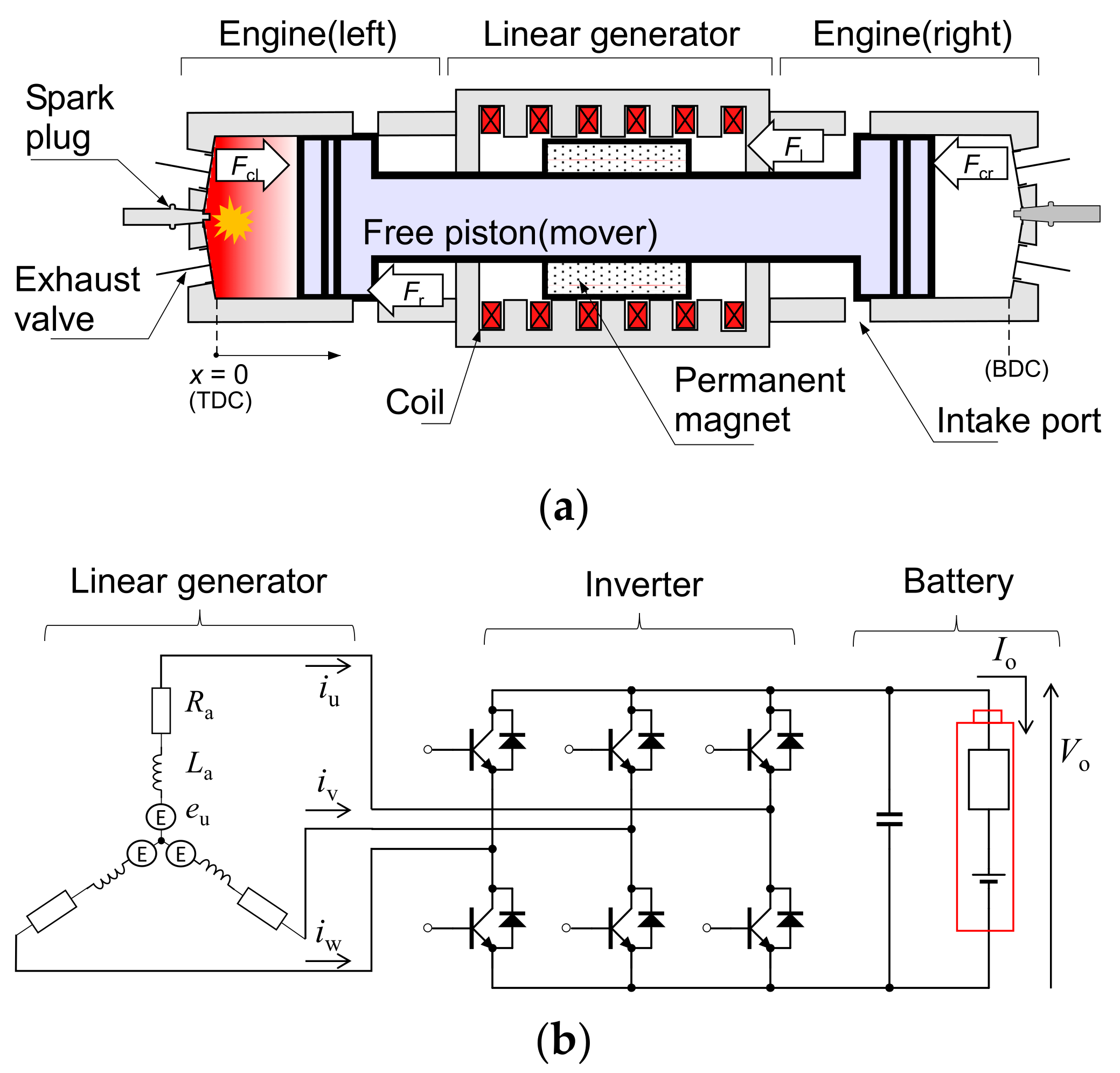
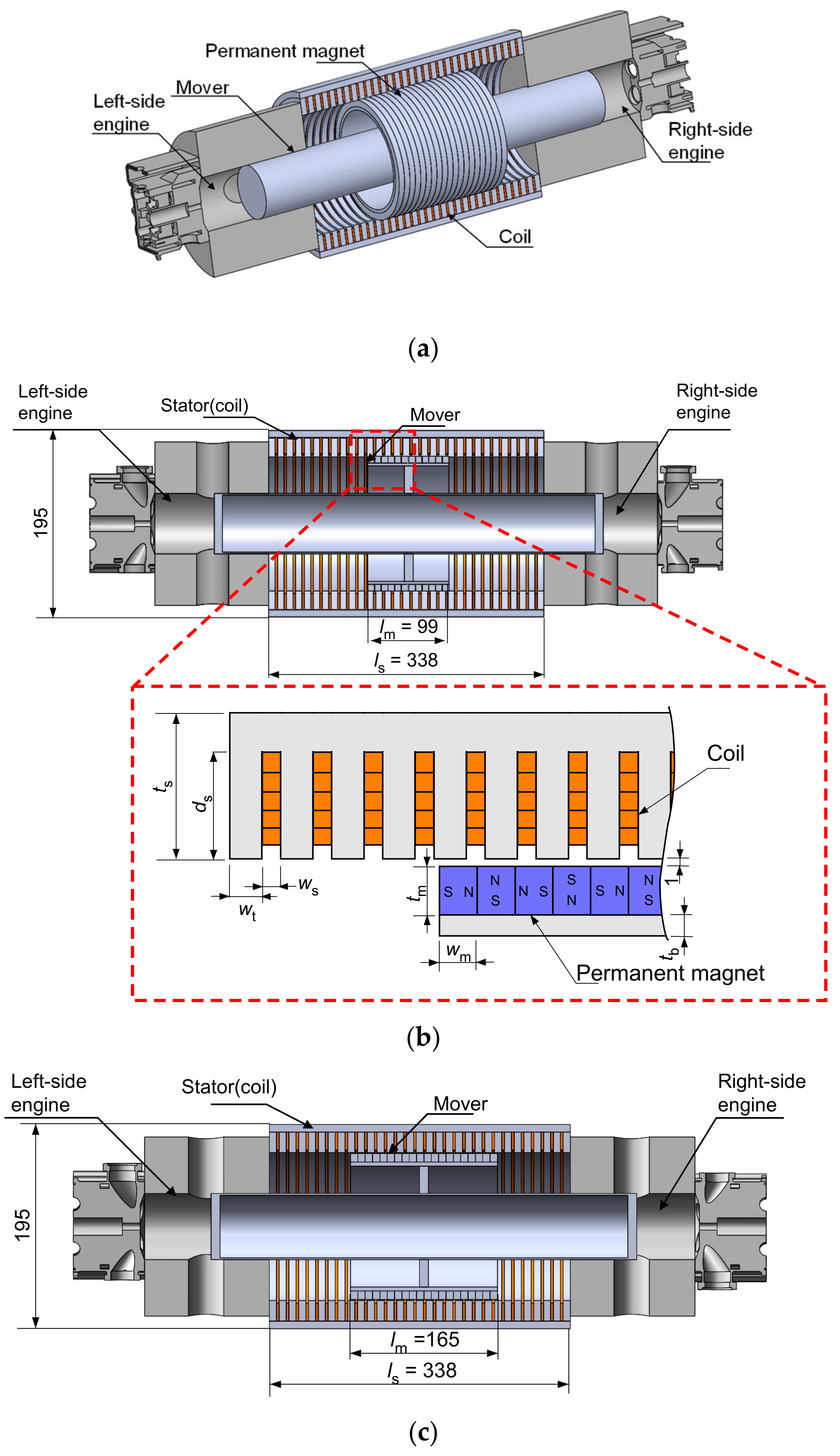
2.1. Structure of FPEG

Figure 1a shows the basic structure of the dual-engine-type FPEG, which has engines facing each other on both sides, sandwiching a linear generator [26,27]. The left and right engines burn alternately, and the combustion force acts on the piston, causing the mover to reciprocate. The equation of motion is given by Equation (1), where m is the mass of the mover. The position x = 0 corresponds to the top dead center (TDC), which is the leftmost end of the mover action. The position x = xb corresponds to the bottom dead center (BDC), which is the rightmost end of the mover action. A permanent magnet is attached to the mover, and the coil is wound in a cylindrical shape, constituting a magnetic movable linear generator [19,22]. The combustion power of the left and right engines is Fcl and Fcr, respectively. The braking thrust Fl acts during power generation. The left- and right-side engines support the mover of the linear generator; thus, a frictional force Fr is generated at the interface between the piston and the cylinder on both sides.
m d 2 x d t 2 = F cl F cr F l F r   ( N )
where m is the piston mass (kg), x is the piston position (m), Fcl is the left-side combustion thrust (N), Fcr is the right-side combustion thrust (N), Fl is the generation braking thrust (N), Fr is the friction thrust (N).
An inverter and a battery are connected to the linear generator, as shown in Figure 1b. The electric power generated by the reciprocating motion of the mover charges the battery through the inverter. The power generation control of the inverter adjusts the power generation current, resulting in variable braking thrust Fl [25,28]. FPEGs without a linear rotation conversion mechanism can easily change the stroke and frequency of piston operation by using power generation control.

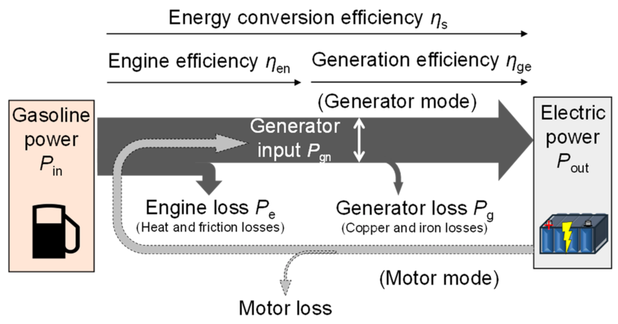
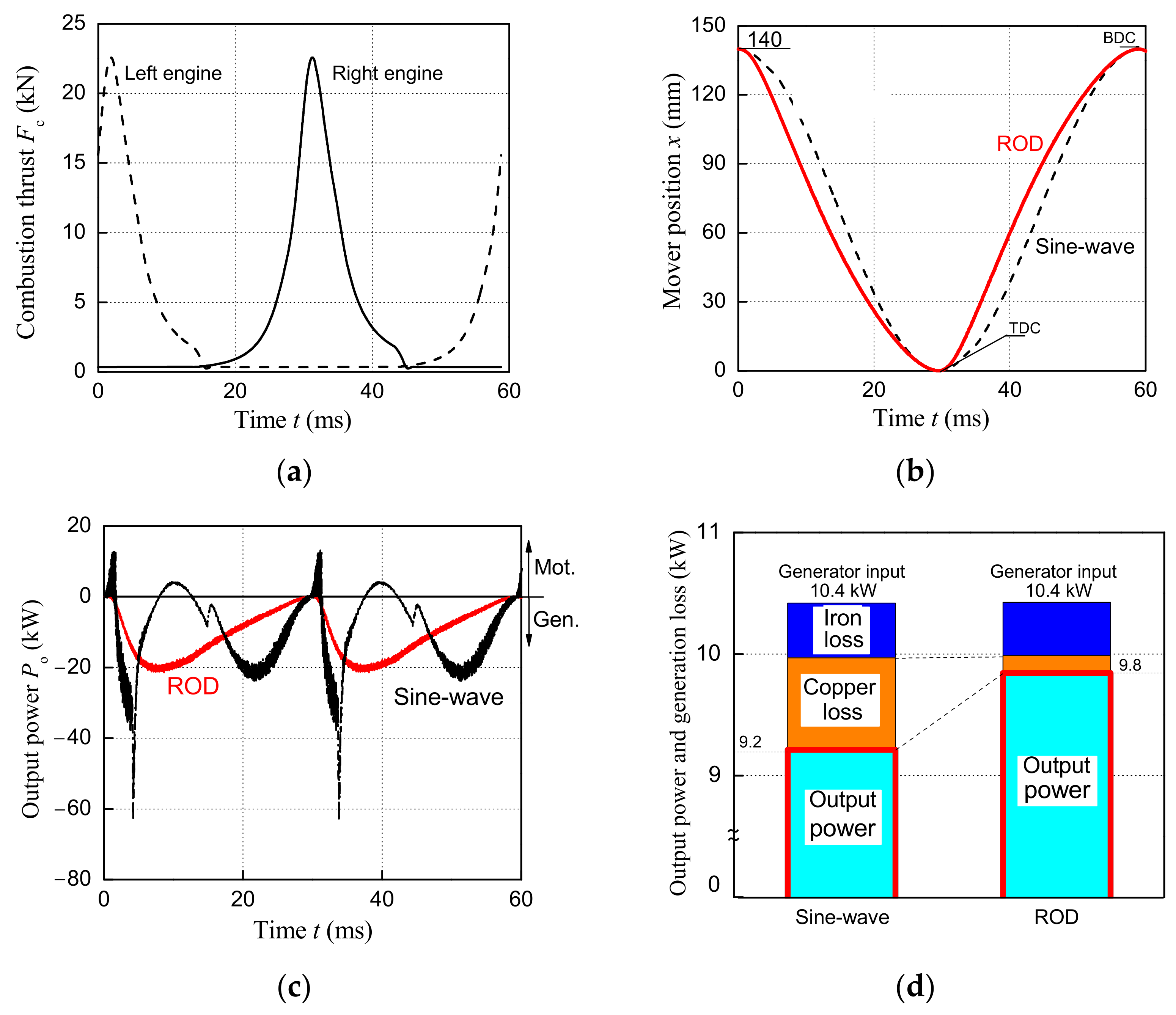
2.2. Energy Flow of FPEG

Figure 2 depicts the energy flow of an FPEG. The rate of heat generation due to gasoline combustion is an input, and the power stored in the battery is output after the loss of the engine and power generation. Energy conversion efficiency ηs herein is defined as the product of engine efficiency ηen and power generation efficiency ηge, which is expressed by Equation (2). Engine efficiency is expressed as the ratio of the gasoline heat generation rate to the generator input, which considers the engine loss (engine heat and friction losses) as expressed by Equation (3). The generation efficiency is the ratio of the output power to the battery to the generator input, which considers the generator loss (iron and copper losses) as expressed by Equation (4). Although a series hybrid battery is connected to a motor for vehicle propulsion, herein, we consider only the powertrain from the engine to the battery through the linear generator.
η s = η en 100 × η ge 100 × 100   %
η en = P in P e P in × 100 = P gn P in × 100   %
η ge = P gn P g P gn × 100 = P out P gn × 100   %
where ηs is the energy conversion efficiency (%), ηen is the engine efficiency (%), ηge is the generation efficiency (%), Pin is the gasoline power (W), Pe is the engine loss (W), Pgn is the generator input (W), Pg is the generator loss (W), and Pout is the system output (W).
The engine loss comprises engine cooling, exhaust, and friction losses. Cooling loss is the heat released from the cylinder interface, and exhaust loss is generated based on thermodynamics due to combustion. The friction loss is due to the contact between the piston ring and the cylinder interface to support the mover. The power generation loss is the sum of the copper and iron losses in the linear generator. Inverter loss is not considered because the effect of the mover operation is small. To improve the energy conversion efficiency, the interrelationship between the efficiency of engine and linear generator should be considered, which is affected by the mover action.
Energy flow is determined by solving the block diagram of Figure 3, which links three software. The mover action is obtained by solving Equation (1) using MATLAB-Simulink (The MathWorks, Inc., Natick, MA, USA), which contains the speci fications of the linear generator designed by JMAG-Designer (JSOL Corporation, Tokyo, Japan) and vector control [15,24]. The combustion thrust, considering the engine loss, is simulated using GT-SUITE (Gamma Technologies, LLC, Westmont, IL, USA).
The air–fuel ratio of the engine simulation is 14.7, which is the theoretical air–fuel ratio of gasoline [28]. The bore diameter of the engine is 50 mm, and the compression ratio is 13, which are assumed to have an output of 11 kW. In addition, the ignition timing is unified so that the combustion thrust is maximized under all conditions. Friction is calculated using the coefficient of friction from the Stribeck curve [14,29].

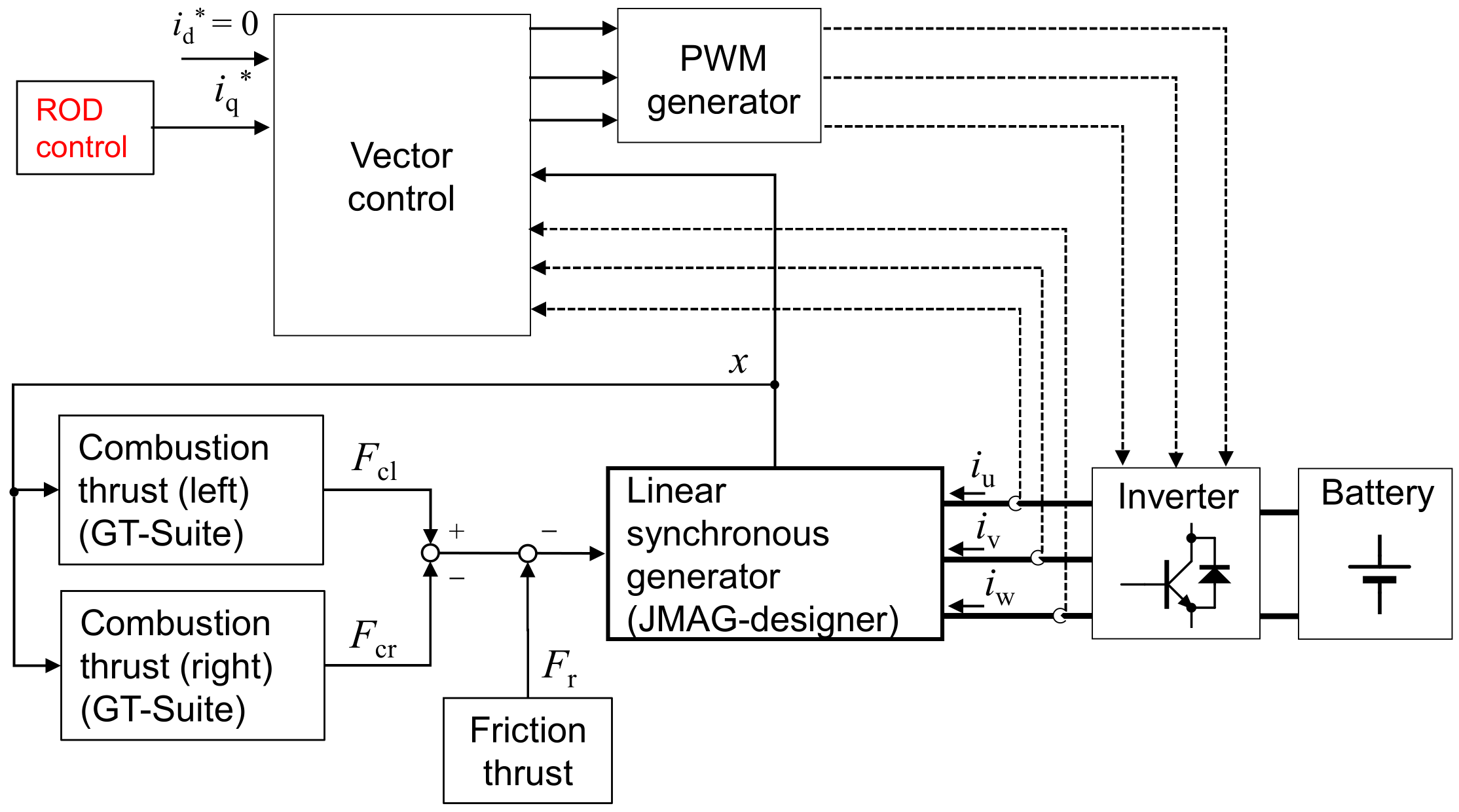
2.3. Braking Thrust Control
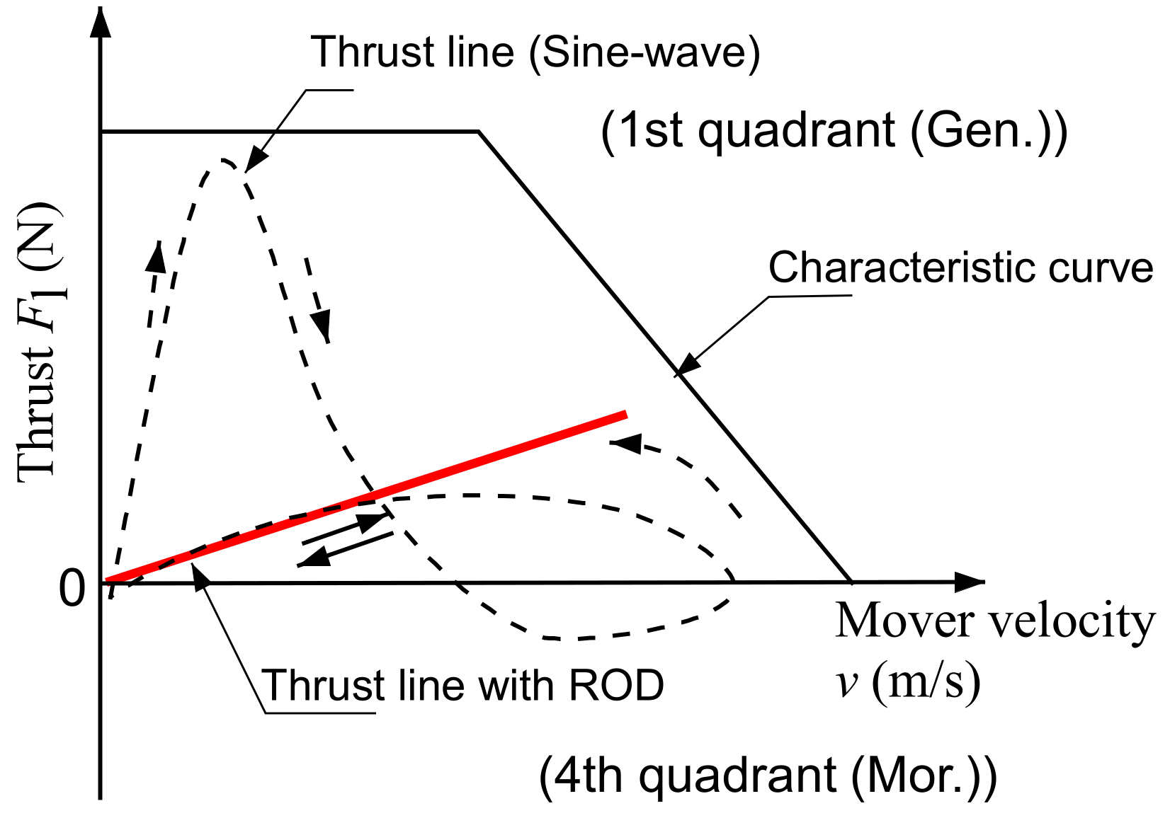
Figure 4 shows the characteristic curve of a linear generator. The movement of the mover from the left to the right engines is a positive speed. Braking thrust acts as a generator in the first quadrant, and the driving thrust acts as a motor in the fourth quadrant. The broken line represents the locus of the power generation braking thrust on the sinusoidal mover displacement. The sinusoidal movement requires a large braking thrust to suppress the acceleration of the mover immediately after combustion. In addition, the driving thrust acts as a motor to match the speed of the sine-wave operation.
Herein, we adopt the resonant output distribution control (ROD), which is based on applying a braking thrust in proportion to the mover velocity, as in a damping system [15], as expressed by Equation (5). The ROD operation with the appropriate setting of braking coefficient can reciprocate with only the braking thrust, which can lead to only the generation mode, as shown by the red line in Figure 4. In addition, suppressing the braking thrust immediately after combustion reduces the maximum current flowing through the linear generator, which improves the generation efficiency.
F l = K l v   ( N )
where Fl is the generation braking thrust (N), Kl is the braking thrust constant (N/(m/s)); v is the mover velocity (m/s).

2.4. Effect of ROD

Figure 5a–c shows the combustion thrust, mover operating waveform, and output power with the application of ROD, respectively. The waveform of the ROD mover motion is distorted compared with a sine-wave because the velocity is not excessively suppressed immediately after combustion. Sine-wave operation requires a large braking thrust, and the maximum output power becomes large to receive the impulse-like combustion thrust. Furthermore, the braking thrust on the sine-wave has a negative region, implying that power is consumed by using the linear generator as the motor. The sine-wave requires driving thrust to accelerate the mover because its speed is maximized at the center of the range of motion. On the contrary, the ROD is driven only in the regenerative mode, and the maximum braking thrust is also suppressed.
Figure 5d compares sine waves and RODs for losses and outputs at the same generator input. Generation loss with ROD is reduced by 50% compared with the sinusoidal operation, and the output power is also increased. In addition, the ROD improved the engine loss through the reduced cooling loss due to the difference in mover speed immediately after combustion, which has a high heat transfer coefficient [28].

3. System Construction Method

This section describes the effects of changing the stroke and the drive frequency of the mover operation under the application of ROD on engine efficiency, considering friction and heat losses. We also propose a method for constructing a system with high energy conversion efficiency by designing a linear generator to improve engine efficiency.

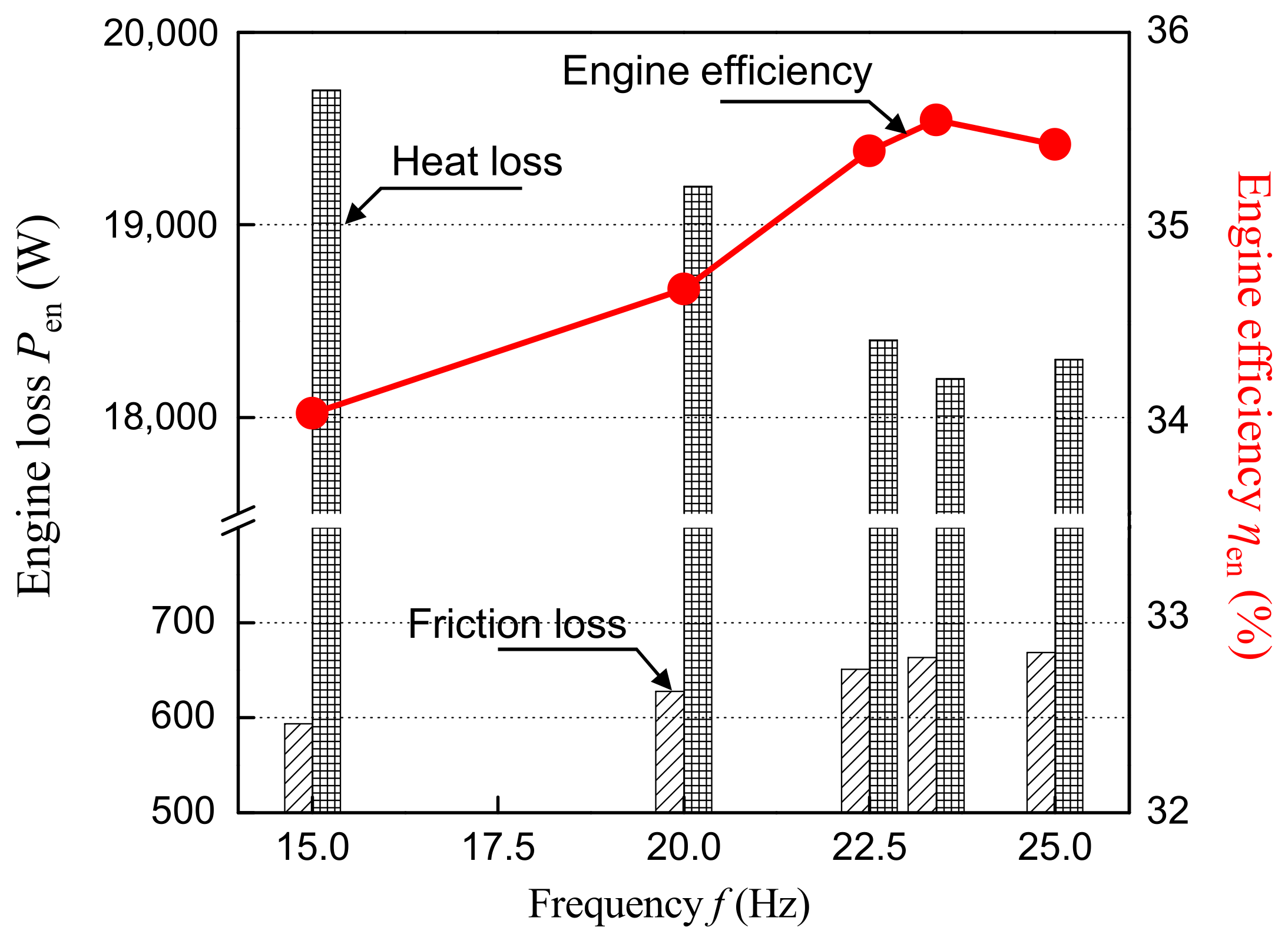
3.1. Effect of Mover Drive Frequency on Engine Efficiency

Figure 6 shows the relationship between the motion frequency of the mover, heat loss, friction loss, and engine efficiency. Equation (6) expresses the amount of heat supplied in one combustion and heat generation rate per second in joules and watts. Increasing the drive frequency reduces heat generation associated with one combustion to obtain the same heat generation rate. The cooling loss is reduced due to the reduction in the amount of heat generated in one combustion and the increase in the average speed due to the increase in frequency. We set the drive frequency as 23 Hz, considering that the decrease in heat loss is a little above 22.5 Hz. Friction is affected by the velocity and magnitude of the combustion thrust, but the former has the greatest effect [14]. Therefore, an increase in the drive frequency increases the average speed, leading to a large friction loss. The trade-off between frequency-dependent heat loss and friction loss provides the maximum range of thermal efficiency. Therefore, the generator design should be considered to satisfy the mover drive frequency for maximum thermal efficiency.
The engine efficiency increases between 15 and 25 Hz, but the improvement effect of the heat loss is small at frequencies above 22.5 Hz. This is because the effect of increasing friction loss is greater than that for improving heat loss above 22.5 Hz.
P in = Q in f   ( W )
where Pin is the heat generation rate per second (W), Qin is the heat supplied in one combustion (J), and f is the mover action frequency (Hz).

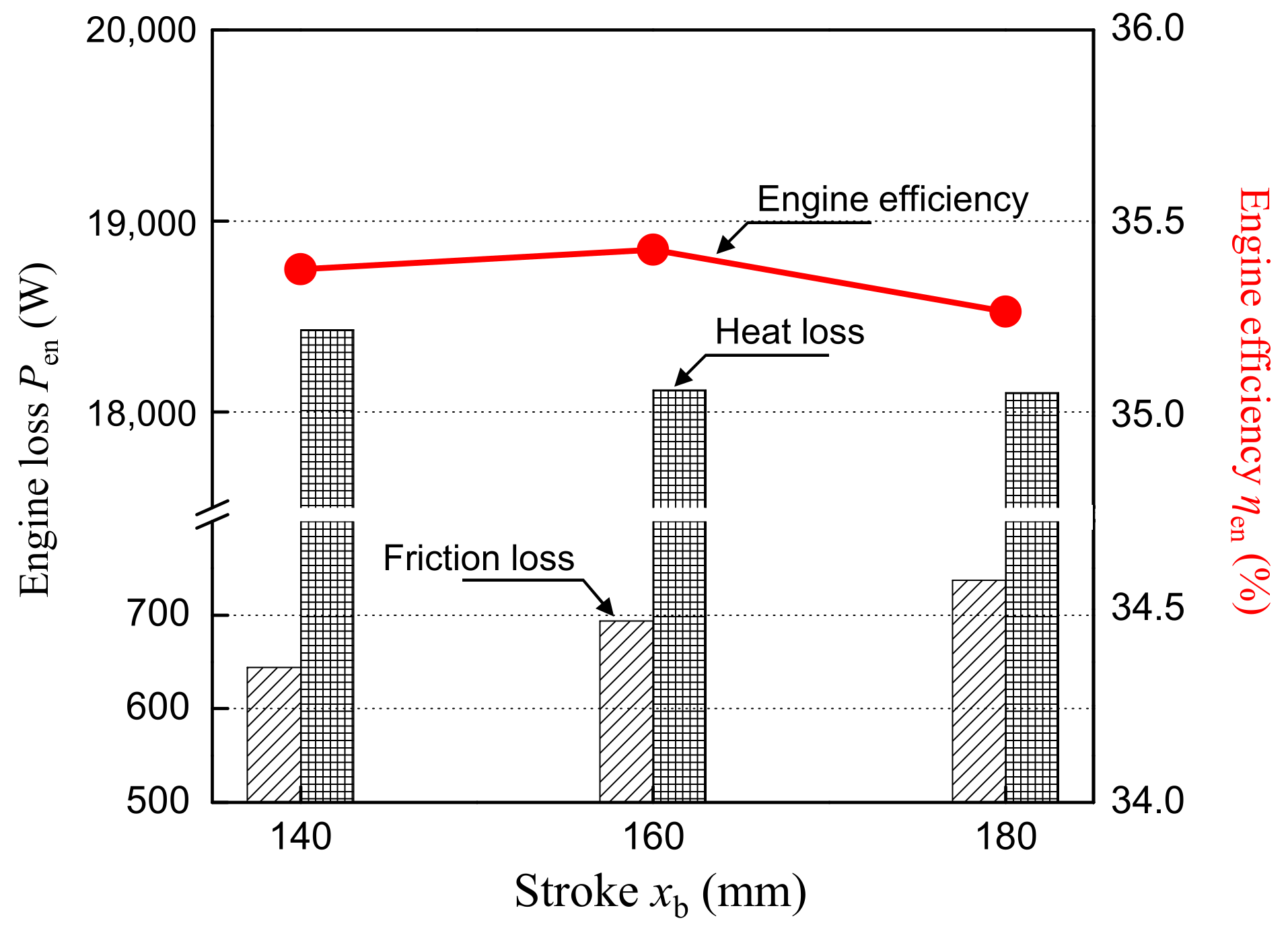
3.2. Effect of Mover Drive Stroke on Engine Efficiency

Figure 7 shows the relationship between the drive stroke of the mover and heat loss, friction loss, and engine efficiency. Stroke extension reduces heat loss, which implies lower exhaust loss, by providing a distance to convert thermal energy into kinetic energy for driving the mover. However, extending the stroke increases the operating range, increasing the friction loss.
Engine efficiency is maximized at a stroke of 160 mm due to the contradictory effects of reducing heat loss and increasing friction loss. The trade-off between stroke-dependent heat loss and friction loss provides the maximum range of thermal efficiency. Therefore, the generator design should be considered to satisfy the mover drive stroke for maximum thermal efficiency.

3.3. Relationship between the Mass and Movement of the Mover

This section summarizes the relationship between the length and mass of the mover for higher engine efficiencies. Extending of the mover length limits the movement stroke and frequency of the mover due to the large mass.
The drive frequency is considered by an impulse response similar to the combustion operation of this system [15]. Equation (7) expresses the motion of the mover given the external force of the impulse under ROD without considering friction. Only a combustion thrust acts like an impulse in the process from the left to the right side, as shown in Figure 5a. The solution of Equation (7) is expressed by Equation (8), which is a similar form of mover motion with ROD, as shown in Figure 5b. The increase in the mover mass requires time to reach BDC, resulting in a lower frequency.
m d 2 x d t 2 = δ t K l d x d t   N
x t = 1 K l 1 e K l m t   m
where m is the piston mass (kg), x is the piston position (m), Kl is the braking thrust constant (N/(m/s)), and δ(t) is the impulse function (N).

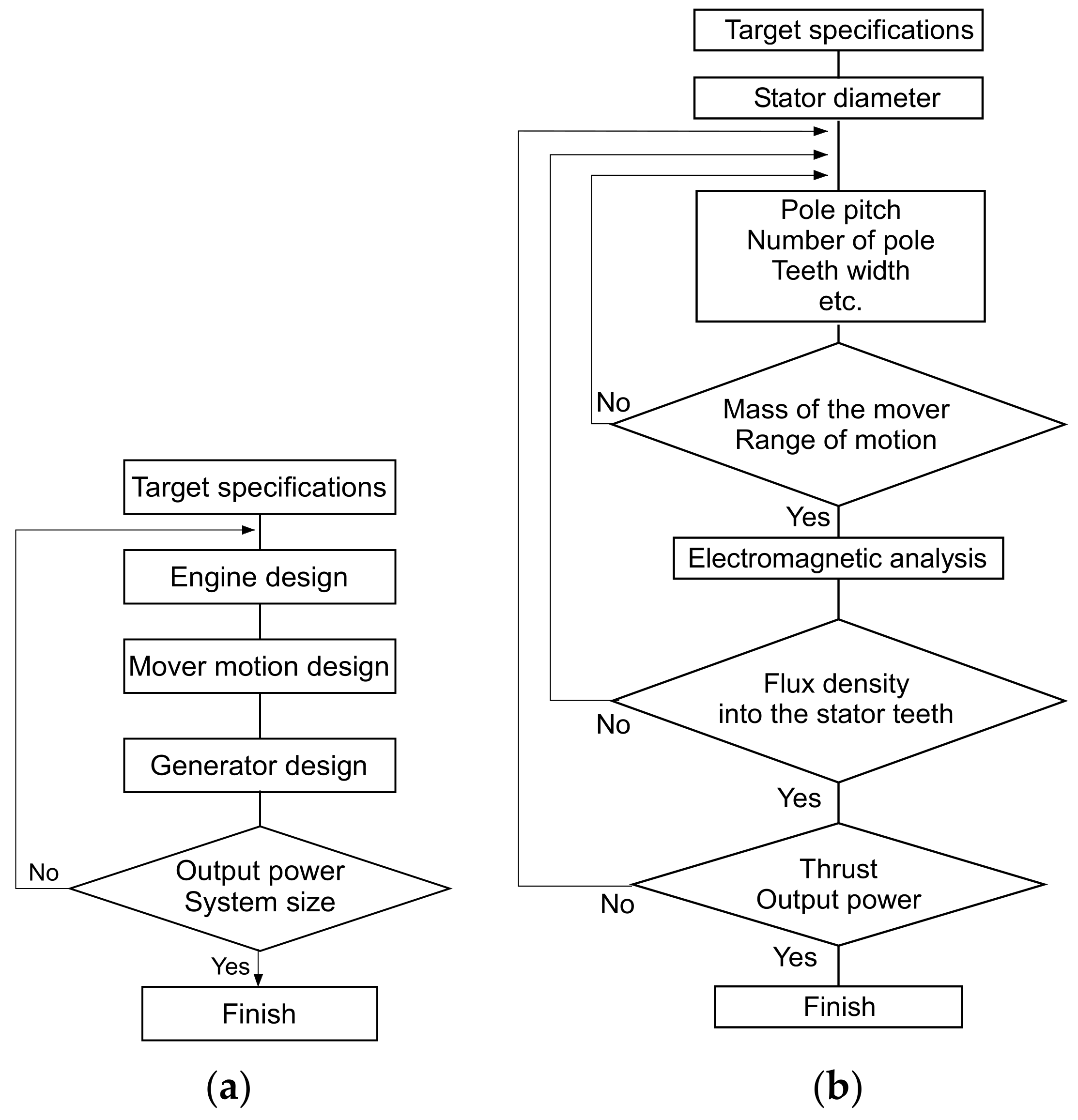
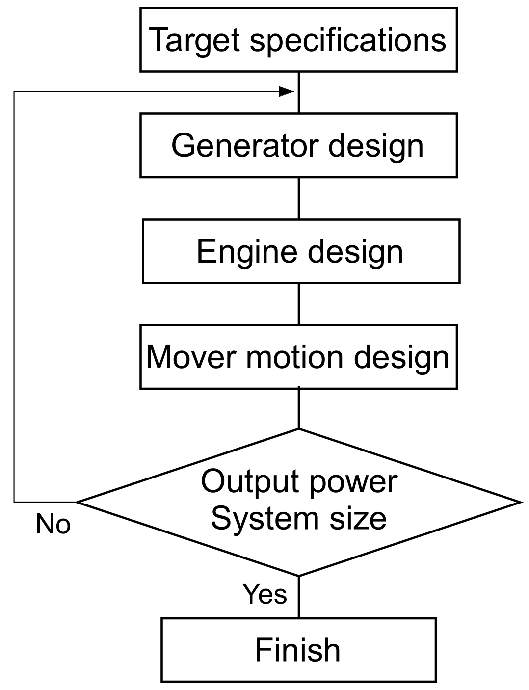
3.4. FPEG Construction Procedure

Section 3.1 and Section 3.2 show the conditions for operating the mover with maximum engine efficiency, and Section 3.3 shows that the length and mass of the mover affect its operation. Figure 8a depicts procedure I for the system construction to realize the mover operation, considering the maximum thermal efficiency. First, the engine and generator dimensions are given as target conditions, considering the output power and output density. Subsequently, the engine specifications are determined considering the output, and the mover motion history for maximum thermal efficiency is set. Next, the specifications of the linear generator, considering the external dimensions, are set to realize the mover motion for maximum thermal efficiency. If the target output is not achieved, the procedure returns to the determination of engine specifications. This procedure builds an FPEG with high energy conversion efficiency by realizing a generator specification that considers the history of mover motion to improve engine efficiency.
Figure 8b shows the design procedure for a cylindrical linear generator for high output density. The diameter of the stator is set within the external dimensions allowable for the linear generator. The allowable operating stroke and mass of the mover are determined by setting the dimensions of the permanent magnet, the number of poles, and the tooth width of the stator, considering the diameter of the mover. The feasibility of the mover operation to improve engine efficiency is confirmed, considering that the length and mass of the mover determines its action range. In addition, the magnetic unsaturation of the stator teeth is confirmed based on the results of electromagnetic field analyses. The design procedure ends when the output of the linear generator meets the target value. If the target output is not achieved, the procedure returns to the determination of engine specifications. Procedure I can design a linear generator that realizes a mover operation for higher engine efficiency, considering that the mover is shared by the engine and the linear generator.

4. Effect of Improving Energy Conversion Efficiency

Section 3 describes the effect of piston operation on engine efficiency and presents the system construction procedure. The engine efficiency is improved by making the motion frequency and stroke of the mover as close as possible to 22 Hz and 160 mm, respectively. This section calculates the energy conversion efficiency of the system construction procedure, considering only the improvement of the power generation efficiency of the linear generator. The proposed method is effective in improving energy conversion efficiency.

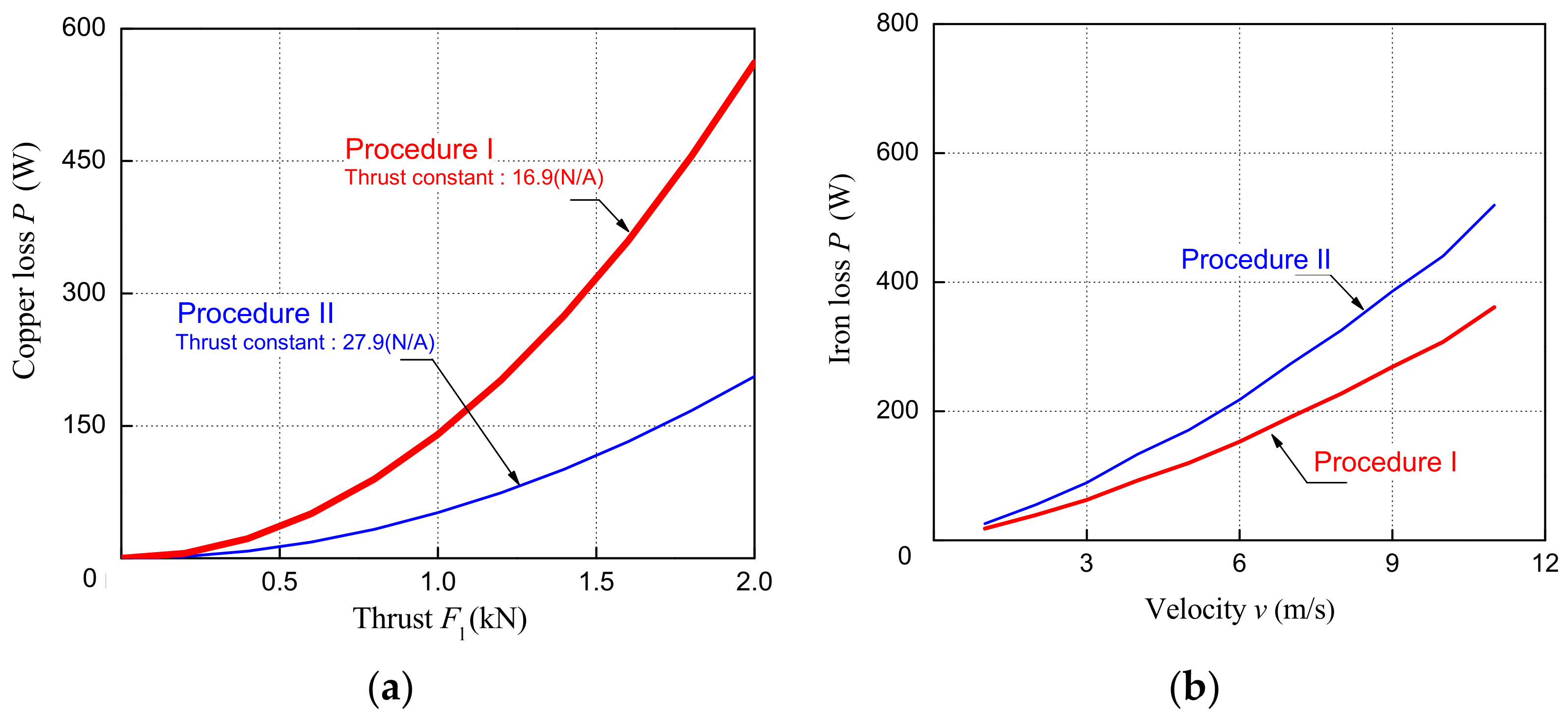
4.1. Differences in Linear Generators for Each Procedure

Figure 9 shows procedure II, which begins with the design of the linear generator. This method limits the operating range of the mover because the mover is too long to maximize the efficiency of the linear generator within the same external dimensions. The extension of the mover results in a larger mass, leading to a lower drive frequency.
Figure 10a shows the structure of the reference linear generator, and Figure 10b,c shows the cross-sectional configuration of the generator designed using procedures I and II, respectively. The linear generator for an 11 kW output is cylindrical to improve the output density, and the stator has the same external dimensions (diameter of 195 mm and length of 338 mm) [22]. Permanent magnets use the Halbach array to improve the thrust constant [17]. Electromagnetic field analyses of a two-dimensional cylindrical coordinate system with a mesh size of 0.2 mm revealed power generation loss and thrust characteristics. Table 1 lists the specifications of the two types of generators. The linear generator in procedure I corresponds to the operating stroke and drive frequency of the mover to improve engine efficiency. The length of the mover and the thickness of the magnet are reduced to lower the weight. However, the linear generator in procedure II is designed with a longer mover within the operable range of the engine, considering only high generation efficiency. Increasing the mover length limits the movable range of the piston and the drive frequency due to the increase in mass.
Figure 11a,b shows the generator efficiency map for procedures I and II, respectively. Figure 12a,b indicates the copper and iron losses for procedures I and II, respectively. Generators with long movers exhibit reduced copper loss due to the higher thrust constant based on the increase in the number of magnet poles. The maximum efficiencies in the efficiency map are 96% and 97% for procedure I and II, respectively, and the high efficiency range of over 96% is wider for procedure II, attributed to the reduction in copper loss. The operating range of the mover, considering the mover size in procedure I, is limited to 16 Hz.
The high efficiency area of the generator in procedure II increases due to the improvement of the thrust constant. On the other hand, the mass of the mover increases as the amount of magnet increases. Therefore, the target drive frequency of the mover cannot be achieved, resulting in a decrease in thermal efficiency.

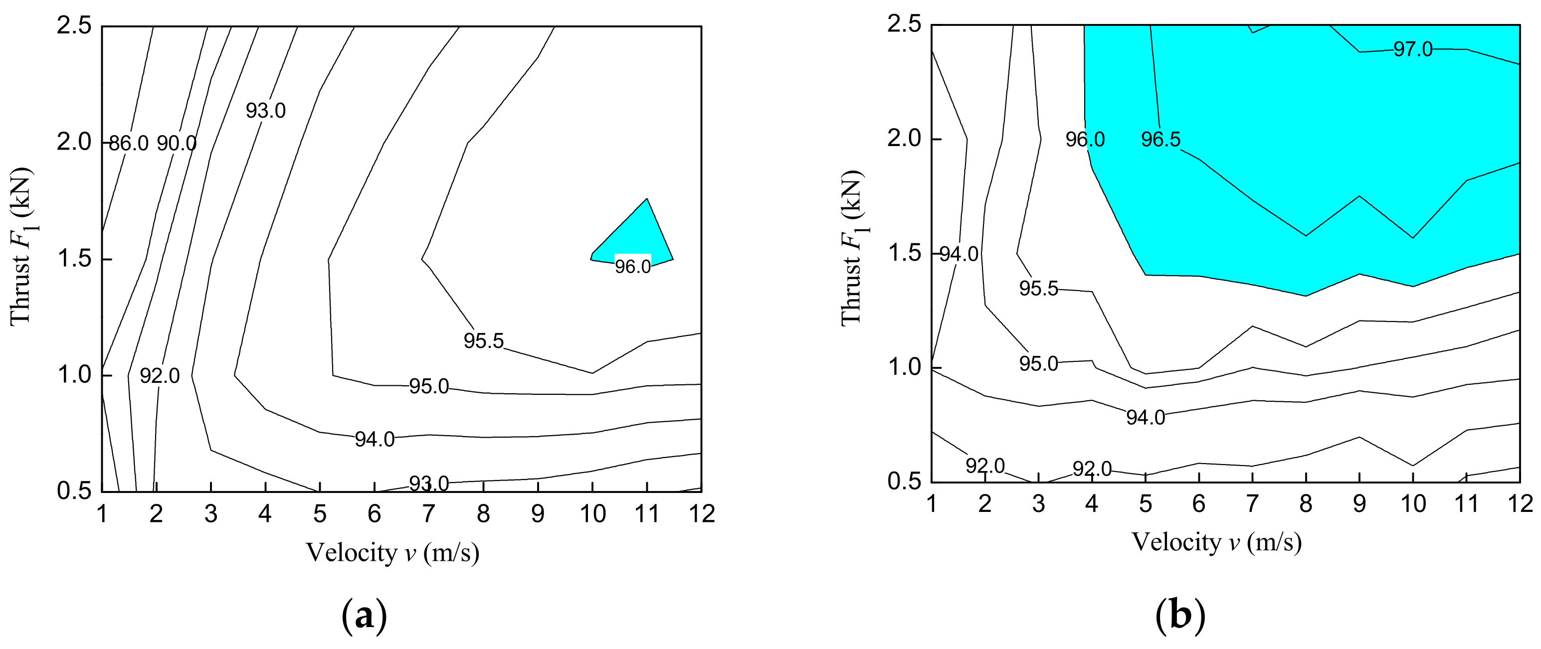
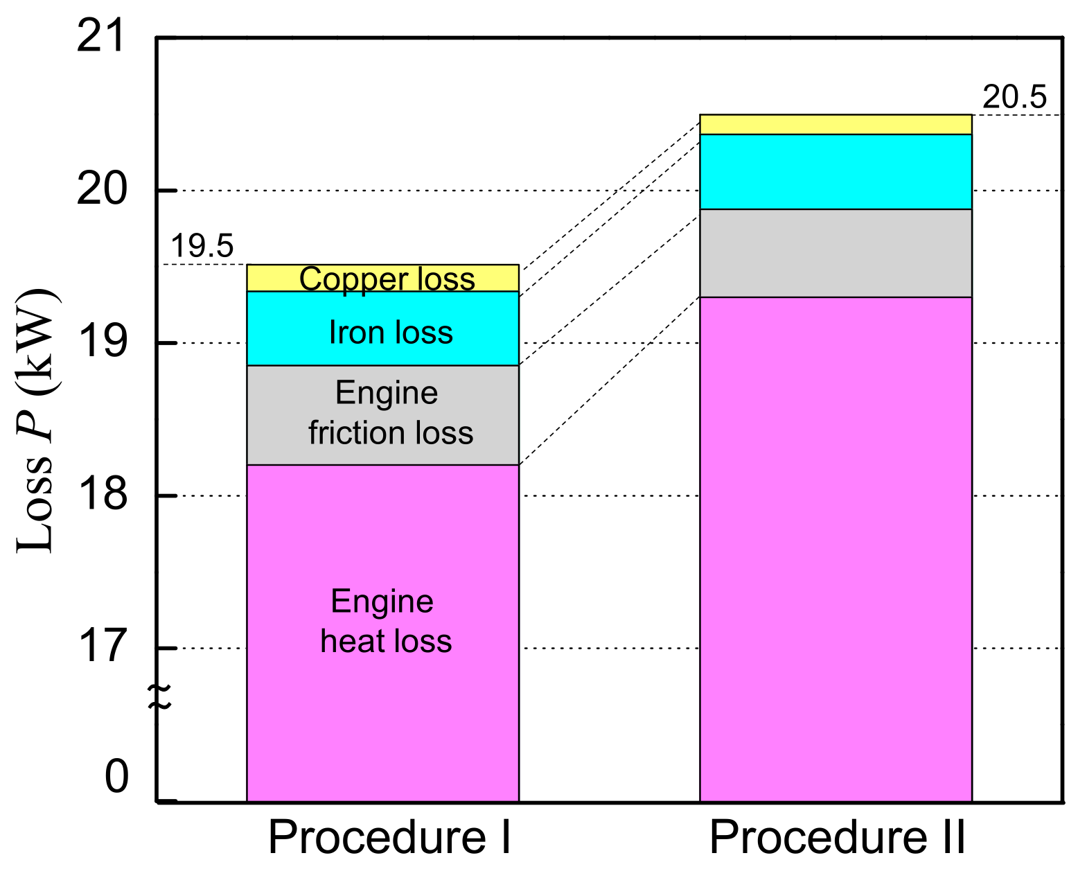
4.2. Effectiveness of the Proposed Procedure

Energy conversion efficiency is estimated based on the setting of the operation history of the mover, considering the difference described in Section 4.1. Table 2 and Figure 13 show the efficiencies and losses for procedures I and II at approximately 10 kW output, respectively, under ROD application at 160 mm stroke. In procedure 2, the power generation efficiency is high by 0.4%, but the engine efficiency is low by 1.1% due to the limitation of the mover operation, which decreases energy conversion efficiency. On the contrary, although the power generation efficiency is low, high engine efficiency is realized in procedure I, improving energy conversion efficiency by 0.9% compared with procedure II. In FPEGs, a large amount of energy is input to the engine, and more than half of the input energy is consumed as heat losses. A return occurs in the output judgment in procedure II shown in Figure 9, and the number of times for redesignation of the generator increases since output does not satisfy the target due to the increase in engine loss. Therefore, setting the mover operation for higher engine efficiency and designing a linear generator to realize the operation can improve the energy conversion efficiency of the FPEG.

5. Conclusions

In FPEGs without a crank, the piston of the engine and the mover of the linear generator are directly connected. The efficiency of the engine and linear generator is affected by the movement of the mover. The mover movement is important for improving overall energy conversion efficiency. Herein, we propose a linear generator design procedure to increase the energy conversion efficiency of FPEG, considering the mover operation. The ROD operation, which acts as a braking thrust similar to the damping system, effectively improves the power generation loss by 50%. Varying the stroke and drive frequency of the mover operation under ROD effectively improves engine efficiency. The procedure for designing generators is effective for improving thermal efficiency, considering the effect of mover length for the operating stroke and drive frequency. The overall efficiency of the proposed procedure is 0.9% higher than that of a generator designed to consider only the improvement of power generation. Designing a linear generator that can realize mover operation that improves engine efficiency effectively reduces the total loss of FPEGs.

Author Contributions

Conceptualization and methodology, M.S. and K.N.; software, S.I., J.Z., and F.N.; validation, S.I. and J.Z.; writing—original draft preparation, M.S. and S.I.; supervision, T.M. and K.N.; funding acquisition, M.S. All authors have read and agreed to the published version of the manuscript.

Funding

This work was supported by JSPS KAKENHI Grant Number 20K14714 and partially by the Nagamori Foundation research grant 2020.

Data Availability Statement

The data presented in this study are available on request from the corresponding author. The data are not publicly available due to large amount of data.

Conflicts of Interest

The authors declare no conflict of interest.

References

  1. Harischandrappa, N.; Bhat, A.K.S. A 10 kW ZVS Integrated Boost Dual Three-Phase Bridge DC–DC Resonant Converter for a Linear Generator-Based Wave-Energy System: Design and Simulation. Electronics 2019, 8, 115. [Google Scholar] [CrossRef] [Green Version]
  2. Liu, C.; Rui, D.; Zhu, H.; Fu, W. Multi-Physical Coupling Field of a Permanent Magnet Linear Synchronous Generator for Wave Energy Conversion. IEEE Access 2021, 9, 85738–85747. [Google Scholar] [CrossRef]
  3. Chen, M.; Huang, L.; Hu, M.; Hu, B.; Ahmad, G. A Spiral Translator Permanent Magnet Transverse Flux Linear Generator Used in Direct-Drive Wave Energy Converter. IEEE Trans. Magn. 2021, 57, 8204705. [Google Scholar] [CrossRef]
  4. Friedrich, L.A.J.; Paulides, J.J.H.; Lomonova, E.A. Modeling and Optimization of a Tubular Generator for Vibration Energy Harvesting Application. IEEE Trans. Magn. 2017, 53, 8209804. [Google Scholar] [CrossRef]
  5. Lee, J.; Chun, Y.; Kim, J.; Park, B. An Energy-Harvesting System Using MPPT at Shock Absorber for Electric Vehicles. Energies 2021, 14, 2552. [Google Scholar] [CrossRef]
  6. Huang, L.; Liu, J.; Yu, H.; Qu, R.; Chen, H.; Fang, H. Winding Configuration and Performance Investigations of a Tubular Superconducting Flux-Switching Linear Generator. IEEE Trans. Appl. Supercond. 2015, 25, 5202505. [Google Scholar] [CrossRef]
  7. Oh, Y.J.; Park, J.S.; Hyon, B.J.; Lee, J. Novel Control Strategy of Wave Energy Converter Using Linear Permanent Magnet Synchronous Generator. IEEE Trans. Appl. Supercond. 2018, 28, 5204705. [Google Scholar] [CrossRef]
  8. Liu, C.; Yu, H.; Hu, M.; Liu, Q.; Zhou, S. Detent Force Reduction in Permanent Magnet Tubular Linear Generator for Direct-Driver Wave Energy Conversion. IEEE Trans. Magn. 2013, 49, 1913–1916. [Google Scholar] [CrossRef]
  9. Huang, W.; Yang, J. A Novel Piecewise Velocity Control Method Using Passivity-Based Controller for Wave Energy Conversion. IEEE Access 2020, 8, 59029–59043. [Google Scholar] [CrossRef]
  10. Xu, Z.; Chang, S. Prototype testing and analysis of a novel internal combustion linear generator integrated power system. Appl. Energy 2010, 87, 1342–1348. [Google Scholar] [CrossRef]
  11. Goto, S.; Moriya, K.; Kosaka, H.; Akita, T.; Hotta, Y.; Umeno, T.; Nakakita, K. Development of Free Piston Engine Linear Generator System Part 2—Investigation of Control System for Generator; SAE International: Warrendale, PA, USA, 2014. [Google Scholar]
  12. Yan, H.; Xu, Z.; Lu, J.; Liu, D.; Jiang, X. A Reciprocating Motion Control Strategy of Single-Cylinder Free-Piston Engine Generator. Electronics 2020, 9, 245. [Google Scholar] [CrossRef] [Green Version]
  13. Hu, Y.; Xu, Z.; Yang, L.; Liu, L. Electromagnetic Loss Analysis of a Linear Motor System Designed for a Free-Piston Engine Generator. Electronics 2020, 9, 621. [Google Scholar] [CrossRef] [Green Version]
  14. Jia, B.; Mikalsen, R.; Smallbone, A.; Roskilly, A.P. A study and comparison of frictional losses in free-piston engine and crankshaft engines. Appl. Ther. Eng. 2018, 140, 217–224. [Google Scholar] [CrossRef]
  15. Sato, M.; Nirei, M.; Yamanaka, Y.; Murata, H.; Bu, Y.; Mizuno, T. Operation Range of Generation Braking Force to Achieve High Efficiency Considering Combustion in a Free-Piston Engine Linear Generator System. IEEJ J. Ind. Appl. 2018, 7, 343–350. [Google Scholar] [CrossRef]
  16. Lu, J.; Xu, Z.; Liu, L. Compression Ratio Control of an Opposed-Piston Free-Piston Engine Generator Based on Artificial Neural Networks. IEEE Access 2020, 8, 107865–107875. [Google Scholar] [CrossRef]
  17. Wang, J.; Howe, D. Tubular modular permanent-magnet machines equipped with quasi-Halbach magnetized magnets-part I: Magnetic field distribution, EMF, and thrust force. IEEE Trans. Magn. 2005, 41, 2470–2478. [Google Scholar] [CrossRef] [Green Version]
  18. Díaz-Pérez, L.C.; Albajez, J.A.; Torralba, M.; Yagüe-Fabra, J.A. Vector Control Strategy for Halbach Linear Motor Implemented in a Commercial Control Hardware. Electronics 2018, 7, 232. [Google Scholar] [CrossRef] [Green Version]
  19. Kosaka, H.; Akita, T.; Moriya, K.; Goto, S.; Hotta, Y.; Umeno, T.; Nakakita, K. Development of Free Piston Engine Linear Generator System Part 1—Investigation of Fundamental Characteristics; SAE Technical Papers 2014-01-1203; SAE International: Warrendale, PA, USA, 2014. [Google Scholar]
  20. Wang, J.; West, M.; Howe, D.; Zelaya-De La Parra, H.; Arshad, W.M. Design and Experimental Verification of a Linear Permanent Magnet Generator for a Free-Piston Energy Converter. IEEE Trans. Energy Convers. 2007, 22, 299–306. [Google Scholar] [CrossRef]
  21. Sato, M.; Nirei, M.; Yamanaka, Y.; Bu, Y.; Mizuno, T. High Power Density by Combining of a Double Stator and an Opposite-magnets Linear Generator in a Dual-type Free-piston Engine Generator. Int. J. Appl. Electromagn. Mech. 2021, 65, 355–370. [Google Scholar] [CrossRef]
  22. Yamanaka, Y.; Nirei, M.; Sato, M.; Murata, H.; Bu, Y.; Mizuno, T. Design of a Linear Synchronous Generator and Examination of the Driving Range for a Free-Piston Engine Linear Generator System. IEEJ J. Ind. Appl. 2018, 7, 351–357. [Google Scholar] [CrossRef] [Green Version]
  23. Moriya, K.; Goto, S.; Akita, T.; Kosaka, H.; Hotta, Y.; Nakakita, K. Development of Free Piston Engine Linear Generator System Part 3—Novel Control Method of Linear Generator for to Improve Efficiency and Stability; SAE Technical Papers 2016-01-0685; SAE International: Warrendale, PA, USA, 2016. [Google Scholar]
  24. Sato, M.; Goto, T.; Zheng, J.; Irie, S. Resonant Combustion Start Considering Potential Energy of Free-Piston Engine Generator. Energies 2020, 13, 5754. [Google Scholar] [CrossRef]
  25. Sato, M.; Naganuma, K.; Nirei, M.; Yamanaka, Y.; Suzuki, T.; Goto, T.; Bu, Y.; Mizuno, T. Improving the Constant-Volume Degree of Combustion Considering Generatable Range at Low-speed in a Free-Piston Engine Linear Generator System. IEEJ Trans. Electr. Electron. Eng. 2019, 14, 1703–1710. [Google Scholar] [CrossRef]
  26. Li, Q.; Xiao, J.; Huang, Z. Simulation of a Two-Stroke Free-Piston Engine for Electrical Power Generation. Energy Fuels 2008, 22, 3443–3449. [Google Scholar] [CrossRef]
  27. Jia, B.; Mikalsen, R.; Smallbone, A.; Zuo, Z.; Feng, H.; Paul, R.A. Piston motion control of a free-piston engine generator: A new approach using cascade control. Appl. Energy 2016, 179, 1166–1175. [Google Scholar] [CrossRef] [Green Version]
  28. Irie, S.; Zheng, J.; Sato, M.; Mizuno, T.; Nishimura, F.; Naganuma, K. Loss-Reduction Effect of Varying the Mover Motion in a Dual-Sided Free-Piston Engine Generator System. In Proceedings of the 13th International Symposium on Linear Drives for Industry Applications (LDIA), Wuhan, China, 1–3 July 2021. [Google Scholar]
  29. Stanley, R.; Taraza, D.; Henein, N.; Bryzik, W. A Simplified Friction Model of the Piston Ring Assembly; SAE Technical Paper 1999-01-0974; SAE International: Warrendale, PA, USA, 1999. [Google Scholar] [CrossRef]
Figure 1. Basic structure of the dual-engine-type FPEG: (a) motion model, (b) circuit model.
Electronics 10 02142 g001
Figure 2. Energy flow of FPEG.
Electronics 10 02142 g002
Figure 3. Block diagram for energy flow simulation.
Electronics 10 02142 g003
Figure 4. Characteristic curve of a linear generator.
Electronics 10 02142 g004
Figure 5. Difference between sine-waves and ROD: (a) combustion thrust (input), (b) piston movement, (c) output electric power, (d) losses.
Electronics 10 02142 g005
Figure 6. Relationship between the action frequency of the mover, thermal loss, friction loss, and engine efficiency.
Electronics 10 02142 g006
Figure 7. Relationship between the mover action stroke, heat loss, friction loss, and engine efficiency.
Electronics 10 02142 g007
Figure 8. FPEG construction procedure: (a) procedure I, (b) linear generator design.
Electronics 10 02142 g008
Figure 9. FPEG construction procedure II (for comparison).
Electronics 10 02142 g009
Figure 10. Structure of the dual-engine-type FPEG (unit: mm): (a) overview, (b) cross-sectional configuration of procedure I, (c) cross-sectional configuration of procedure II.
Electronics 10 02142 g010
Figure 11. Efficiency map of linear generators: (a) procedure I, (b) procedure II.
Electronics 10 02142 g011
Figure 12. Loss of linear generators: (a) copper loss, (b) iron loss.
Electronics 10 02142 g012
Figure 13. Simulation results of losses.
Electronics 10 02142 g013
Table 1. Specifications of generators.
ItemProcedure IProcedure II
Dimensions of stator (mm)195 × 338
    Radial thickness of stator ts (mm)31.5
    Depth of slot ds (mm)23
    Width of slot ws (mm)3
    Width of teeth wt (mm)8.0
    Number of slots30
    Armature core material20HX1200
(Nippon Steel Corporation, Tokyo, Japan)
Dimensions of mover (mm)130 × 165130 × 99
    Number of poles53
    Width of magnet wm (mm)8.25
    Thickness of magnet tm (mm)10.58.25
    Thickness of back yoke tb (mm)4.53.5
    Air gap (mm)1
    Mover bake yoke material20HX1200
(Nippon Steel Corporation, Tokyo, Japan)
    Permanent magnet materialNEOMAX-42AH
(Hitachi Metals, Ltd., Tokyo, Japan)
Resistance of armature coil Ra (mW/Phase)40.1
Inductance of armature coil La (mH/Phase)0.68
Thrust constant Kf (N/A)27.916.9
Mass of mover m (kg)7.213.68
Table 2. Simulation results for energy conversion efficiency.
ItemProcedure IProcedure II
Mover action frequency (Hz)22.014.7
Engine efficiency ηen (%)35.534.4
Generation efficiency ηge (%)93.694.0
Energy conversion efficiency ηen (%)33.232.3
Publisher’s Note: MDPI stays neutral with regard to jurisdictional claims in published maps and institutional affiliations.

