
Performance Evaluation of Solar PV Inverter Controls for Overvoltage Mitigation in MV Distribution Networks


Abstract
:1. Introduction
2. Research Method
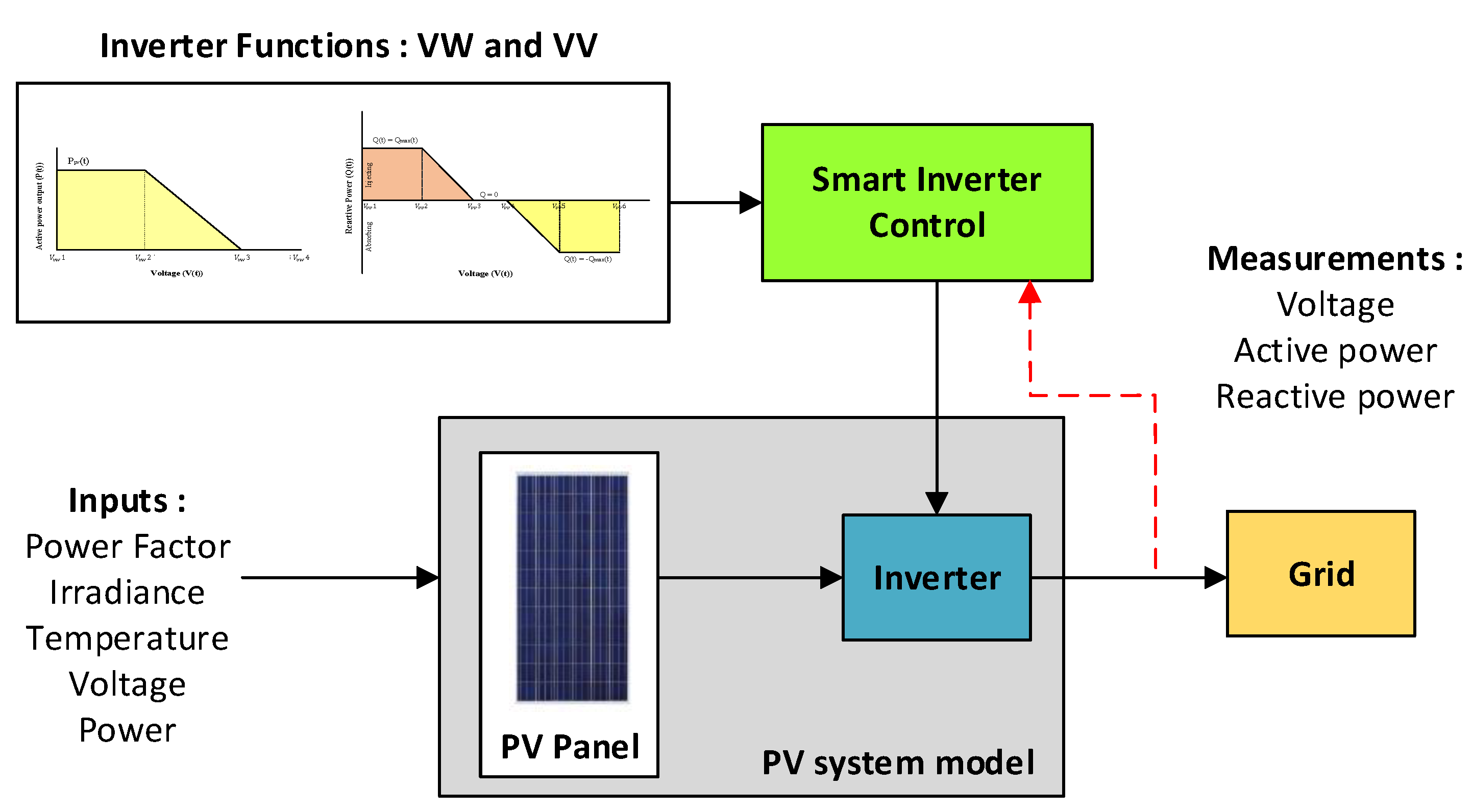
2.1. Voltage Control Functionalities of Solar PV Inverters
2.1.1. Active Power Curtailment of Solar PV Inverters
2.1.2. Reactive Power Absorption of Solar PV Inverters
2.2. Methodology
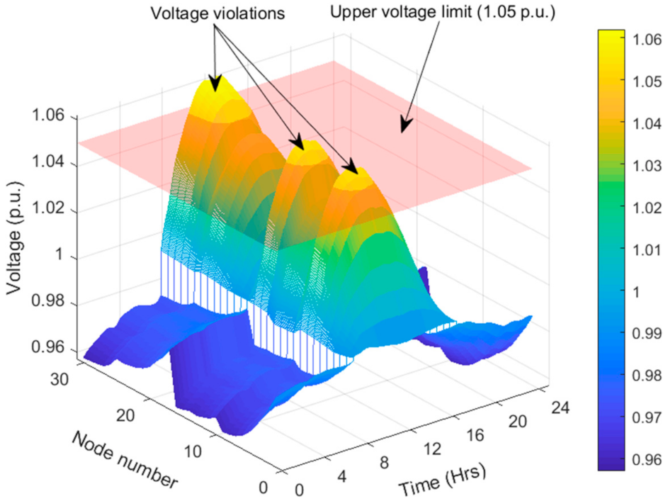
- Number of nodes with voltage infringements: The daily voltage profiles of all nodes after the implementation of inverter controllers were evaluated for conformity with the local voltage limits, and the number of nodes that do not meet with permissible limits was obtained. According to the statutory limits specified by the Malaysian electric utility, Tenaga Nasional Berhad (TNB) for voltages in MV networks, the maximum and minimum voltage levels are 1.05 and 0.95 p.u., respectively.
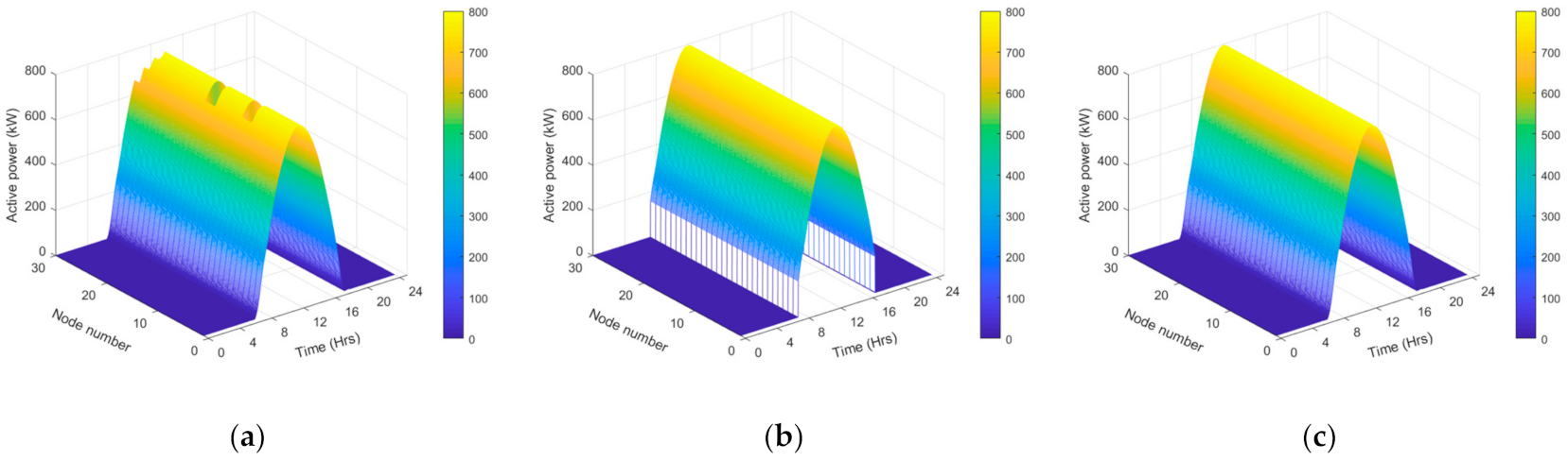
- Total daily average APC: The total daily average difference between the uncontrolled active power output at a unity power factor and the active power output of inverters with respective inverter controllers was computed.
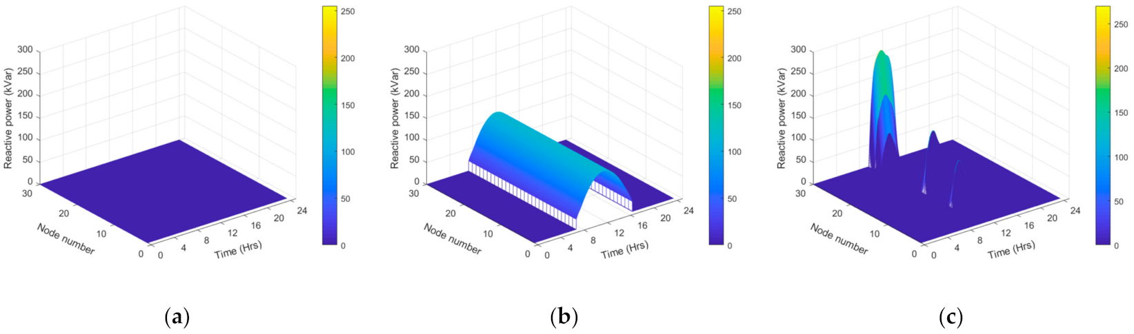
- Total daily average RPA: The daily average reactive power absorption with respective inverter controllers was computed.
- Total daily average network loss: The daily average network loss of the entire system with respective inverter controllers was computed.
3. Case Study
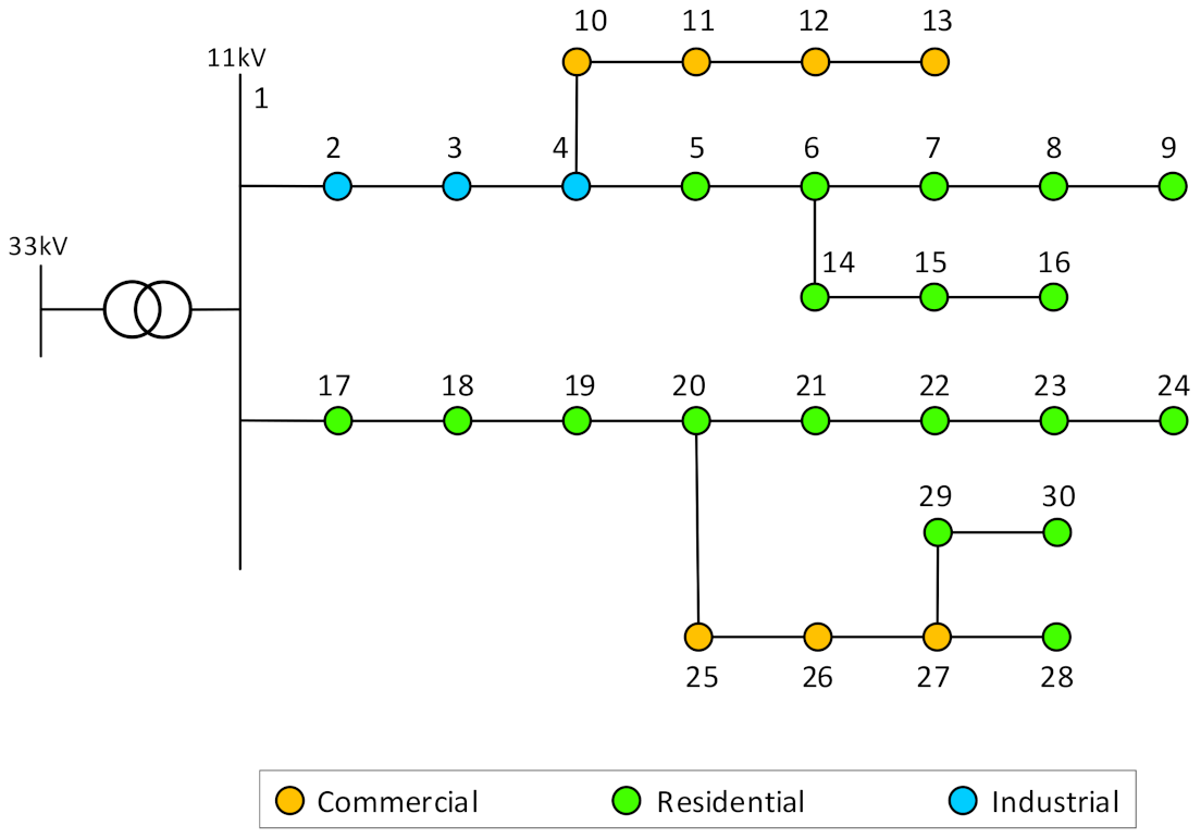
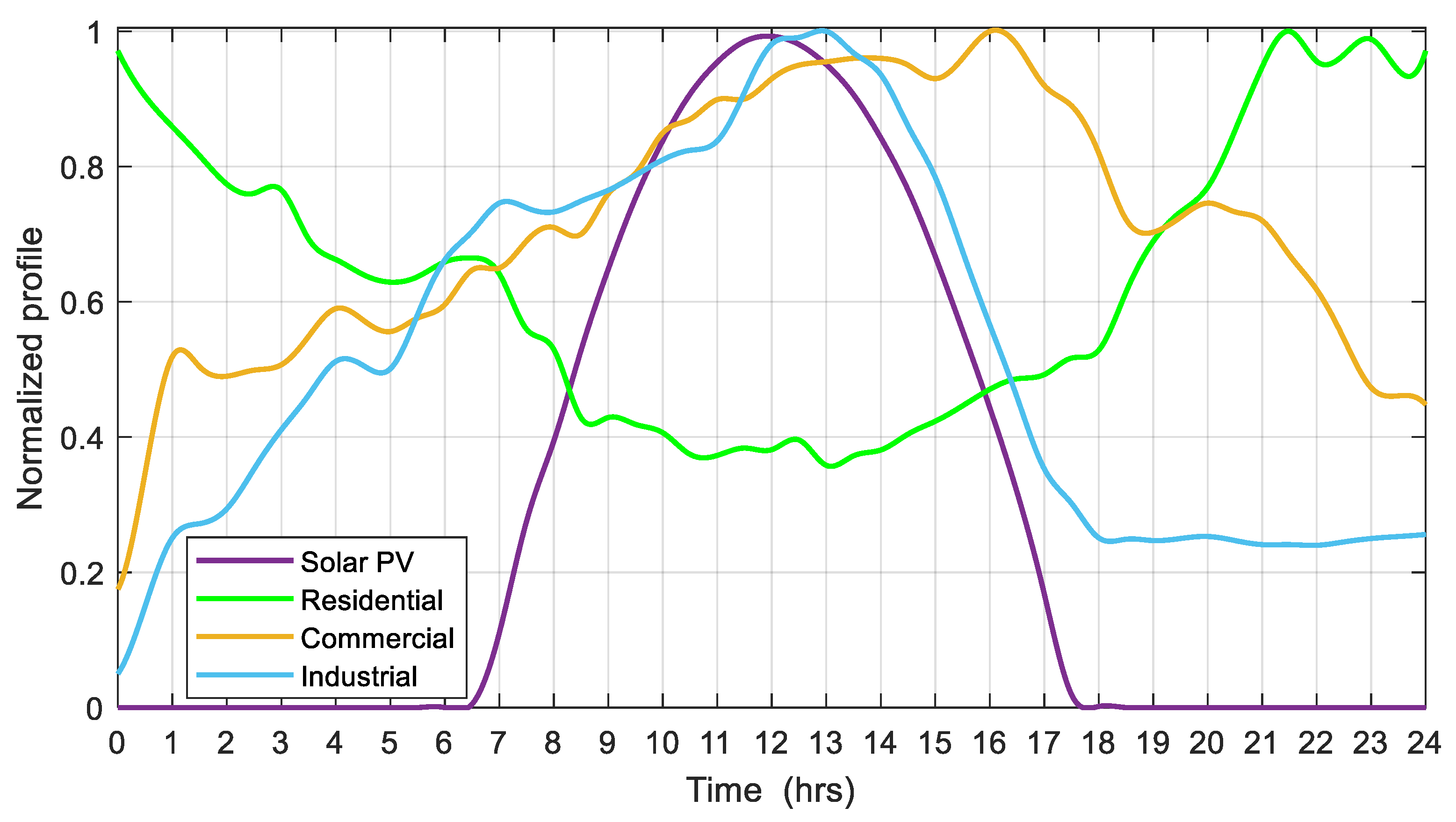
3.1. Test Network
3.2. Controller Parameter Settings
- Base Case: The power factor of all solar PV inverters connected to the network was set to unity (the reactive power in-feed from the PV was 0).
- Volt–Watt control: The voltage setpoints were adjusted to commence the active power curtailment at 1.048 p.u. and to completely curtail the generation when the voltage reached the Malaysian upper voltage statutory limit for the MV distribution networks (1.05 p.u.).
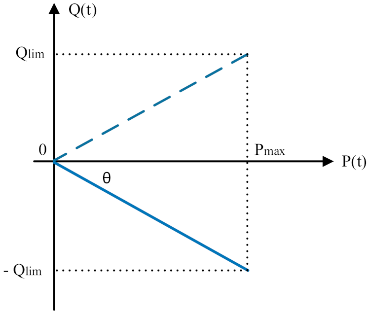
- Fixed power factor control: The power factor of all solar PV inverters connected to the network was fixed at 0.98 (leading).
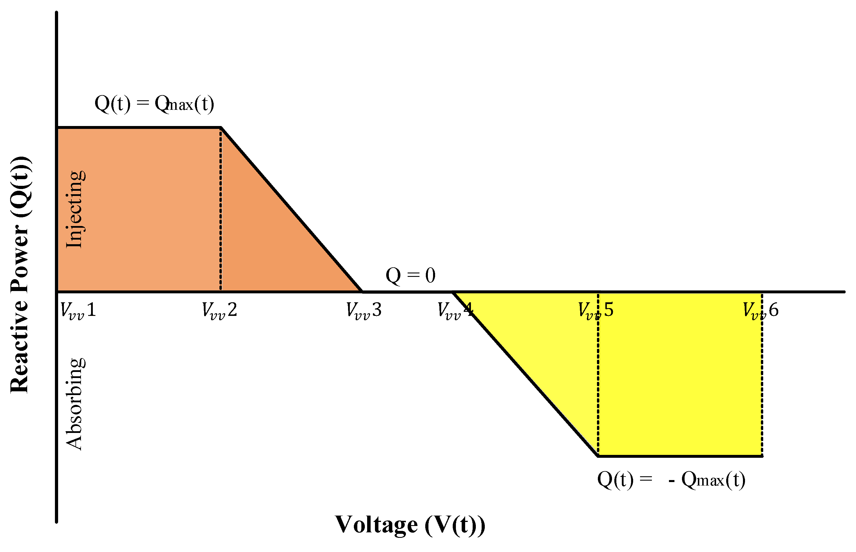
- Volt–Var control: The and setpoints (Figure 3) were adjusted to the lower and upper Malaysian statutory voltage limits for the MV distribution networks (0.95 and 1.05 p.u.). The and voltage setpoints were adjusted to enable the inverter to inject reactive power until the voltage reached 0.955 p.u. and to start to absorb reactive power when the voltage reached 1.045 p.u.
4. Results
5. Discussion
6. Conclusions
Author Contributions
Funding
Acknowledgments
Conflicts of Interest
Abbreviations
| PV | Photovoltaic |
| MV | Medium Voltage |
| DERs | Distributed Energy Resources |
| DNOs | Distribution Network Operators |
| APC | Active Power Curtailment |
| RPA | Reactive Power Absorption |
| PCC | Point of Common Coupling |
| Computed active power output by Volt–Watt control | |
| Terminal voltage | |
| Voltage setpoint 1 of Volt–Watt control | |
| Voltage setpoint 2 of Volt–Watt control | |
| Voltage setpoint 3 of Volt–Watt control | |
| Voltage setpoint 4 of Volt–Watt control | |
| Apparent power rating of the PV inverter | |
| Active power output of the PV inverter | |
| , | Reactive power capability of the PV inverter |
| Maximum possible reactive power of the PV inverter | |
| Maximum active power generation of the PV inverter | |
| Computed reactive power injection by Volt–Var control | |
| Voltage setpoint 1 of Volt–Var control | |
| Voltage setpoint 2 of Volt–Var control | |
| Voltage setpoint 3 of Volt–Var control | |
| Voltage setpoint 4 of Volt–Var control | |
| Voltage setpoint 5 of Volt–Var control | |
| Voltage setpoint 6 of Volt–Var control |
Appendix A

| Line Segment | Length (km) | Impedance (Ω/km) | |
|---|---|---|---|
| From Bus | To Bus | ||
| 1 | 2 | 1.7 | 0.08 + j0.0949 |
| 2 | 3 | 1.6 | |
| 3 | 4 | 1.9 | |
| 4 | 5 | 1.7 | 0.1609 + j0.1524 |
| 5 | 6 | 1.5 | |
| 6 | 7 | 2.4 | |
| 7 | 8 | 1.9 | |
| 8 | 9 | 2.7 | |
| 4 | 10 | 2.5 | |
| 10 | 11 | 1.3 | |
| 11 | 12 | 1.0 | |
| 12 | 13 | 1.7 | |
| 6 | 14 | 2.3 | |
| 14 | 15 | 2.6 | |
| 15 | 16 | 2.5 | |
| 1 | 17 | 1.5 | 0.08 + j0.0949 |
| 17 | 18 | 2.0 | |
| 18 | 19 | 1.5 | |
| 19 | 20 | 2.0 | |
| 20 | 21 | 2.0 | 0.1609 + j0.1524 |
| 21 | 22 | 2.0 | |
| 22 | 23 | 1.5 | |
| 23 | 24 | 2.5 | |
| 20 | 25 | 2.0 | |
| 25 | 26 | 2.5 | |
| 26 | 27 | 2.0 | |
| 27 | 28 | 2.0 | |
| 27 | 29 | 2.0 | |
| 29 | 30 | 2.0 | |
References
- Karimi, M.; Mokhlis, H.; Naidu, K.; Uddin, S.; Bakar, A.H.A. Photovoltaic penetration issues and impacts in distribution network—A review. Renew. Sustain. Energy Rev. 2016, 53, 594–605. [Google Scholar] [CrossRef]
- Alboaouh, K.A.; Mohagheghi, S. Impact of rooftop photovoltaics on the distribution system. J. Renew. Energy 2020, 2020, 1–23. [Google Scholar] [CrossRef]
- Almeida, D.; Abeysinghe, S.; Ekanayake, M.P.; Godaliyadda, R.I.; Ekanayake, J.; Pasupuleti, J. Generalized approach to assess and characterise the impact of solar PV on LV networks. Int. J. Electr. Power Energy Syst. 2020, 121, 106058. [Google Scholar] [CrossRef]
- Aziz, T.; Ketjoy, N. PV penetration limits in low voltage networks and voltage variations. IEEE Access 2017, 5, 16784–16792. [Google Scholar] [CrossRef]
- Yan, R.; Saha, T.K. Investigation of voltage stability for residential customers due to high photovoltaic penetrations. IEEE Trans. Power Syst. 2012, 27, 651–662. [Google Scholar] [CrossRef]
- Zhao, J.; Wang, C.; Zhao, B.; Lin, F.; Zhou, Q.; Wang, Y. A review of active management for distribution networks: Current status and future development trends. Electr. Power Compon. Syst. 2014, 42, 280–293. [Google Scholar] [CrossRef]
- National Renewable Energy Laboratory. Advanced Inverter Functions to Support High Levels of Distributed Solar: Policy and Regulatory Considerations; National Renewable Energy Laboratory: Golden, CO, USA, 2014. [Google Scholar]
- Xavier, L.S.; Cupertino, A.F.; Pereira, H.A. Ancillary services provided by photovoltaic inverters: Single and three phase control strategies. Comput. Electr. Eng. 2018, 70, 102–121. [Google Scholar] [CrossRef]
- Pierno, A.; Di Noia, L.P.; Rubino, L. Ancillary services provided by PV power plants. Leonardo Electron. J. Pract. Technol. 2016, 15, 57–76. [Google Scholar]
- Almeida, D.; Pasupuleti, J.; Ekanayake, J. Assessing the performance of smart inverter functionalities in PV-Rich LV distribution networks. In Proceedings of the 2020 IEEE Student Conference on Research and Development (SCOReD), Batu Pahat, Johor, Malaysia, 27–29 September 2020; pp. 90–95. [Google Scholar] [CrossRef]
- Lemkens, K.; Geth, F.; Vingerhoets, P.; Deconinck, G. Reducing overvoltage problems with active power curtailment—Simulation results. In Proceedings of the 2013 4th IEEE/PES Innovative Smart Grid Technologies Europe, ISGT Europe 2013, Lyngby, Denmark, 6–9 October 2013; pp. 1–5. [Google Scholar]
- Tonkoski, R.; Lopes, L.A.C.; EL-Fouly, T.H.M. Droop-based active power curtailment for overvoltage prevention in grid connected PV inverters. IEEE Int. Symp. Ind. Electron. 2010, 2388–2393. [Google Scholar] [CrossRef]
- Alyami, S.; Wang, Y.; Wang, C.; Zhao, J.; Zhao, B. Adaptive real power capping method for fair overvoltage regulation of distribution networks with high penetration of PV systems. IEEE Trans. Smart Grid 2014, 5, 2729–2738. [Google Scholar] [CrossRef]
- Gómez-González, J.F.; Cañadillas-Ramallo, D.; González-Díaz, B.; Méndez-Pérez, J.A.; Rodríguez, J.; Sánchez, J.; Guerrero-Lemus, R. Reactive power management in photovoltaic installations connected to low-voltage grids to avoid active power curtailment. Renew. Energy Power Qual. J. 2018, 1, 5–11. [Google Scholar] [CrossRef]
- Almeida, D.; Pasupuleti, J.; Ekanayake, J.; Karunarathne, E. Mitigation of overvoltage due to high penetration of solar photovoltaics using smart inverters volt/var control. Indones. J. Electr. Eng. Comput. Sci. 2020, 19, 1259–1266. [Google Scholar] [CrossRef]
- Smith, J.W.; Sunderman, W.; Dugan, R.; Seal, B. Smart inverter volt/var control functions for high penetration of PV on distribution systems. In Proceedings of the 2011 IEEE/PES Power Systems Conference and Exposition, PSCE 2011, Phoenix, AZ, USA, 20–23 March 2011; pp. 1–6. [Google Scholar]
- Demirok, E.; González, P.C.; Frederiksen, K.H.B.; Sera, D.; Rodriguez, P.; Teodorescu, R. Local reactive power control methods for overvoltage prevention of distributed solar inverters in low-voltage grids. IEEE J. Photovolt. 2011, 1, 174–182. [Google Scholar] [CrossRef]
- Reno, M.J.; Broderick, R.J.; Grijalva, S. Smart inverter capabilities for mitigating over-voltage on distribution systems with high penetrations of PV. In Proceedings of the IEEE Photovoltaic Specialists Conference, Tampa, FL, USA, 20–25 June 2013; pp. 3153–3158. [Google Scholar]
- IEEE Standard Association. IEEE Std. 1547-2018. Standard for Interconnection and Interoperability of Distributed Energy Resources with Associated Electric Power Systems Interfaces; IEEE: Piscataway, NJ, USA, 2018. [Google Scholar]
- California Public Utilities Commission. Rule 21 Generating Facility Interconnections; California Public Utilities Commission: San Francisco, CA, USA, 2014. [Google Scholar]
- Hawaii Public Utility Commission. Revised Rule 14H; Hawaii Public Utility Commission: Honolulu, HI, USA, 2018. [Google Scholar]
- Farkas, C.; Tóth, A.; Orlay, I. Voltage control methods in the MV grid with a large share of PV. Int. J. Emerg. Electr. Power Syst. 2019, 20, 1–12. [Google Scholar] [CrossRef]
- Adiguno, F.K.; Mai, T.T.; Nguyen, P.H. Mitigation impact of large-scale PV integration on MV distribution network with sequential control functions: A case of study in Noordwolde grid, the Netherlands. In Proceedings of the 25th International Conference and Exhibition on Electricity Distribution, Madrid, Spain, 3–6 June 2019; pp. 1–5. [Google Scholar] [CrossRef]
- Shi, Q.; Feng, W.; Zhang, Q.; Wang, X.; Li, F. Overvoltage mitigation through Volt-VAR control of distributed PV systems. In Proceedings of the 2020 IEEE/PES Transmission and Distribution Conference and Exposition, Chicago, IL, USA, 12–15 October 2020; pp. 1–5. [Google Scholar] [CrossRef]
- Kryonidis, G.C.; Demoulias, C.S.; Papagiannis, G.K. A probabilistic evaluation of voltage control strategies in active MV networks. In Proceedings of the 2017 52nd International Universities Power Engineering Conference, Heraklion, Greece, 28–29 August 2017; pp. 1–6. [Google Scholar] [CrossRef]
- Hoke, A. Fast Grid Frequency Support from Distributed Inverter-Based Resources; National Renewable Energy Laboratory: Golden, CO, USA, 2018. [Google Scholar]


| Parameter | Value | |
|---|---|---|
| Capacity | 30 MVA | |
| Voltage | 33/11 kV | |
| Number of feeders | 2 | |
| Number of nodes | 30 | |
| Load connected | Feeder 1 | 3.47 MW |
| Feeder 2 | 2.53 MW | |
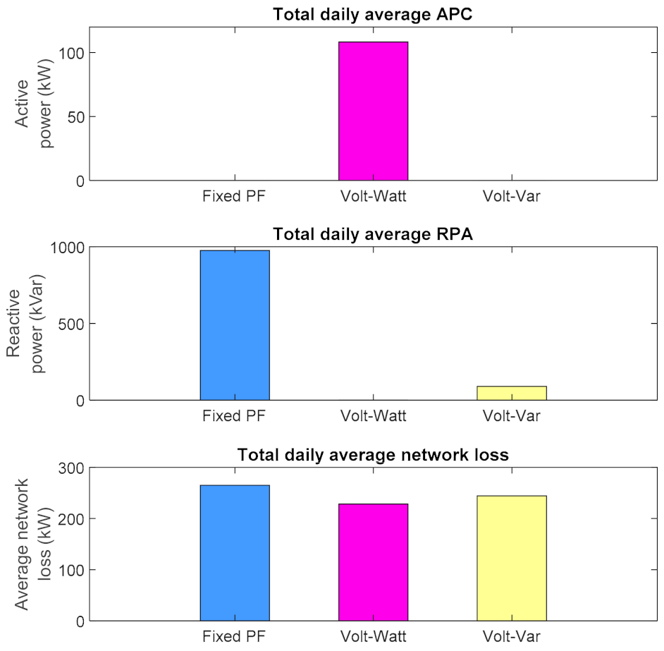
| Parameter | Base Case | Advanced Inverter Functionality | ||
|---|---|---|---|---|
| Volt–Watt Control | Fixed Power Factor Control | Volt–Var Control | ||
| Number of nodes with voltage infringements | 7 | 0 | 0 | 0 |
| Total daily average APC (kW) | - | 108.238 | - | - |
| Total daily average RPC (kVar) | - | - | 975.244 | 89.098 |
| Total daily average network loss (kW) | 242.857 | 228.234 | 264.971 | 244.319 |
Publisher’s Note: MDPI stays neutral with regard to jurisdictional claims in published maps and institutional affiliations. |
© 2021 by the authors. Licensee MDPI, Basel, Switzerland. This article is an open access article distributed under the terms and conditions of the Creative Commons Attribution (CC BY) license (https://creativecommons.org/licenses/by/4.0/).
Share and Cite
Almeida, D.; Pasupuleti, J.; Raveendran, S.K.; Basir Khan, M.R. Performance Evaluation of Solar PV Inverter Controls for Overvoltage Mitigation in MV Distribution Networks. Electronics 2021, 10, 1456. https://doi.org/10.3390/electronics10121456
Almeida D, Pasupuleti J, Raveendran SK, Basir Khan MR. Performance Evaluation of Solar PV Inverter Controls for Overvoltage Mitigation in MV Distribution Networks. Electronics. 2021; 10(12):1456. https://doi.org/10.3390/electronics10121456
Chicago/Turabian StyleAlmeida, Dilini, Jagadeesh Pasupuleti, Shangari K. Raveendran, and M. Reyasudin Basir Khan. 2021. "Performance Evaluation of Solar PV Inverter Controls for Overvoltage Mitigation in MV Distribution Networks" Electronics 10, no. 12: 1456. https://doi.org/10.3390/electronics10121456