Article

Electromechanical Coupling Parameter Identification for Flexible Conductor Wire Interconnection Considering Interaction Effect in Microwave Circuits

1
Key Laboratory of Electronic Equipment Structure Design, Xidian University, Ministry of Education, Xi’an 710071, China
2
Xi’an Institute of Space Radio Technology, Xi’an 710100, China
3
CETC No.38 Research Institute, Hefei 230088, China
*
Author to whom correspondence should be addressed.
Electronics 2021, 10(4), 464; https://doi.org/10.3390/electronics10040464
Submission received: 20 January 2021 / Revised: 10 February 2021 / Accepted: 11 February 2021 / Published: 14 February 2021
(This article belongs to the Section Microwave and Wireless Communications)

Abstract

:
With the huge requirement of high frequency, multi-function and high reliability, the quality of microwave circuit interconnection has become an important factor that significantly affects the improvement of microwave electronic system performance. This paper has presented an identification method for flexible conductor wire interconnection (FCWI) electromechanical coupling parameters in microwave circuits with the consideration of their interaction effect. First, a parametric characterization cascade function has been proposed to design the FCWI, and consequently, a three-dimensional electromagnetic structure model of FCWI has been developed and verified. In order to identify the electromechanical coupling parameters of the flexible interconnection considering the interaction effect effectively, this paper has used the range multi-objective function to select the optimal level of the configuration parameter of the flexible interconnection that affects the signal transmission loss. Based on the variance analysis and range analysis of the experimental results, the comprehensive judgment criterion of electromechanical coupling parameters of flexible interconnection can be defined, and therefore, the calculation of electromechanical coupling degree can be derived and the electromechanical coupling property identification of flexible interconnection has been obtained. An example has been used afterwards to verify the accuracy of the proposed method. The method proposed in this paper can be a promising tool for microwave circuit comprehensive design and the optimization of its interconnection, considering both mechanical reliability and electrical performance.

1. Introduction

Microwave circuits are widely used in the fields of Internet of Things (IOT) communication, radar detection, electronic countermeasures and so on. As the key component of a high frequency electronic system, the development of the microwave integrated circuit is developing towards high speed, high reliability, multi-function and miniaturization [1,2,3]. In the microwave circuit, on one hand, with the increase in the electromagnetic transmission frequency, the influence of the structure of the microwave circuit interconnection on the signal transmission is becoming more and more intensified. At the same time, the interconnection configuration will be forced to deform under the influence of the environmental stress load, which will further affect the electrical signal transmission. The superposition of the two parts can cause the failure of the electrical transmission function of the module in some extreme cases [4,5]. On the other hand, mechanical reliability problems in the process of design, manufacture and operation of the microwave circuit interconnection can directly cause circuit function failure [6]. Therefore, in order to improve the quality of microwave circuit development, the impact of the circuit interconnection on signal transmission should be considered.
For the study of microwave circuit interconnection in a harsh environment, it is usually necessary to characterize the mechanical, electrical and thermal characteristics of the interconnection. Based on the multi physical field model, the influence of interconnection structure and environmental load on the transmission performance of the circuit can be analyzed effectively [7]. When the interconnection structure is complex, it is necessary to extract the parameters to characterize the interconnection geometry accurately. Then, full wave analysis, neural network or equivalent circuit method can be used to further develop the correlation model between configuration parameters and electrical parameters [8,9]. In order to improve the electromagnetic transmission performance, a 3D coaxial interconnection has been designed in [10], which was applied to die-to-die interconnection in system-in-package (SiP). By reducing the impedance discontinuity, the signal transmission performance can be significantly improved. For the determined structure of circuit interconnection, such as the coaxial-to-microstrip transitions, the high frequency transmission performance of interconnection can be improved by changing the surrounding structure of interconnection to suppress the electromagnetic radiation of the interconnection, or adding a metal ring around the interconnection as the electromagnetic mutation buffer [11,12]. However, these studies have not considered the influence of interconnection parameters on signal transmission, nor do they consider the reliability of interconnection under extreme environmental conditions. The mechanical connection of microwave circuit interconnection should have good reliability, which is a prerequisite for excellent interconnection signal transmission performance. In [13], a robust principle component analysis (RPCA) based inspection model for the appearance of integrated circuit solder joints has been proposed, and the solder joint quality was evaluated accordingly. Wang, et al [14] has developed a three-dimensional electromagnetic field model and a distributed circuit model of bonding wire, and combined with an experimental test, the impact of bonding wire interconnection failure on signal transmission in an a radio frequency (RF) circuit was studied. A coupling analysis method based on an equivalent circuit to analyze the performance of lead wire interconnects with defects has been proposed in [15], and by developing an equivalent circuit for lead wire interconnects with cracks, the prediction of transmission loss of interconnects with defects is obtained. However, there is a lack of research that considers both improving the mechanical reliability of the microwave circuit interconnection and maintaining the robustness of signal transmission performance, and the degree of influence of the interconnection configuration parameters on signal transmission loss is not clear.
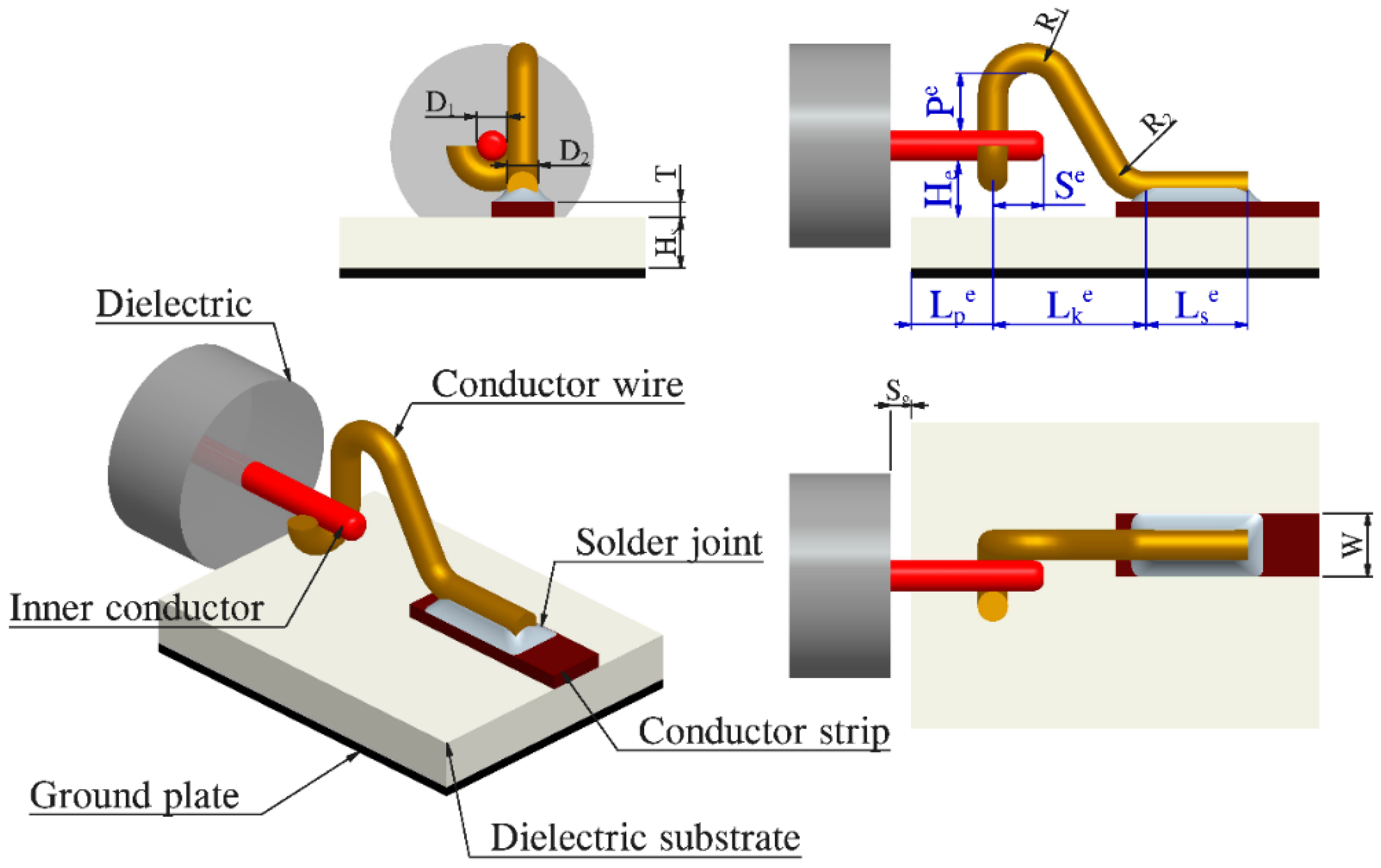
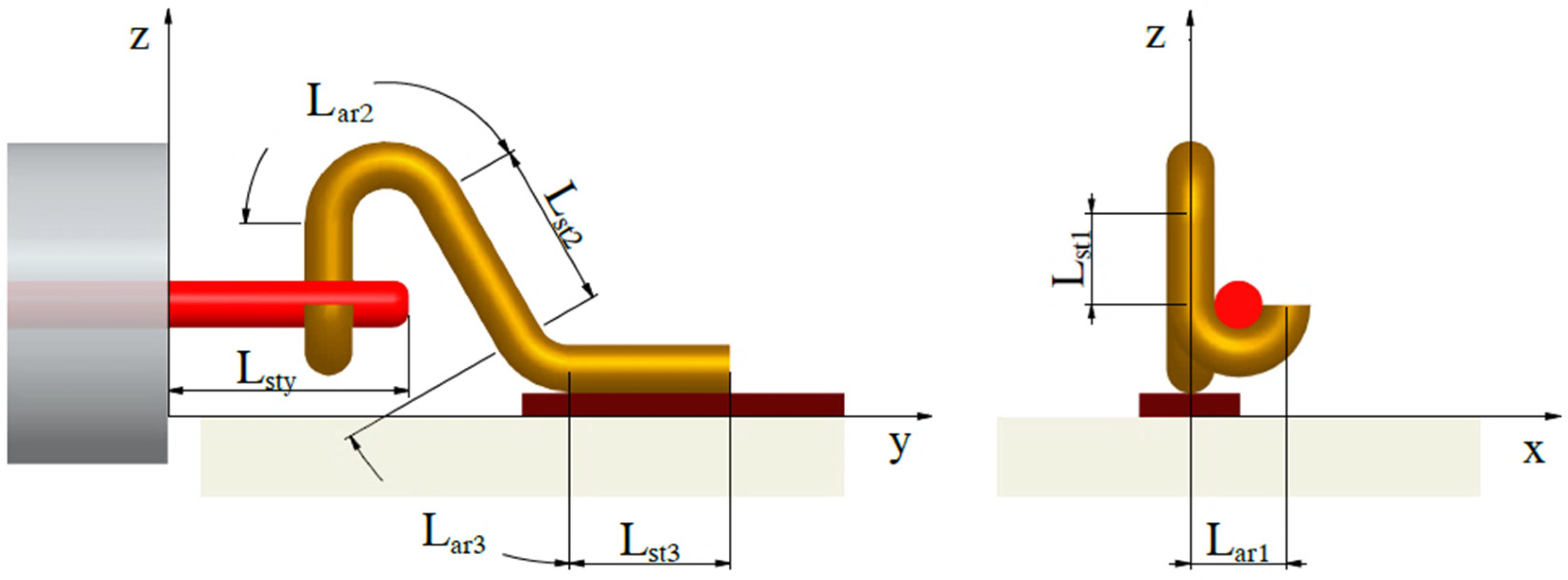
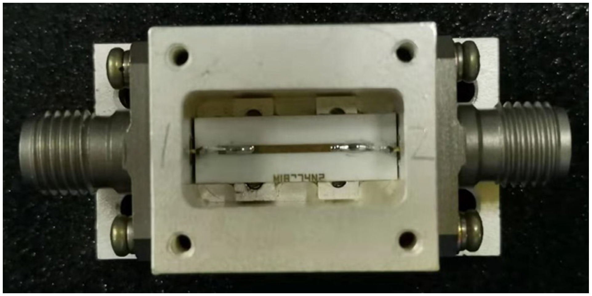
In this paper, the typical coaxial to microstrip conversion structure in a microwave circuit has been analyzed. By using flexible conductor wire interconnection (FCWI) instead of the rigid connection of traditional solder, the internal stress and external load of interconnection can be buffered, and the reliability of interconnection has been improved. However, the interconnection configuration of flexible conductor wires changes the discontinuity of the signal transmission path, which can have a significant impact on the transmission performance of high frequency microwave signals. Therefore, this paper proposed a method to identify the electromechanical coupling parameters of FCWI in a microwave circuit, considering the interaction effect. Based on this method, the interconnection configuration can be parameterized and accurately characterized, the electromechanical coupling parameters can be identified, and the influence degree of electromechanical coupling can be quantified. This work can lay a theoretical foundation for the regulation of microwave circuit interconnection reliability and electrical performance.
This paper is organized as follows. In 
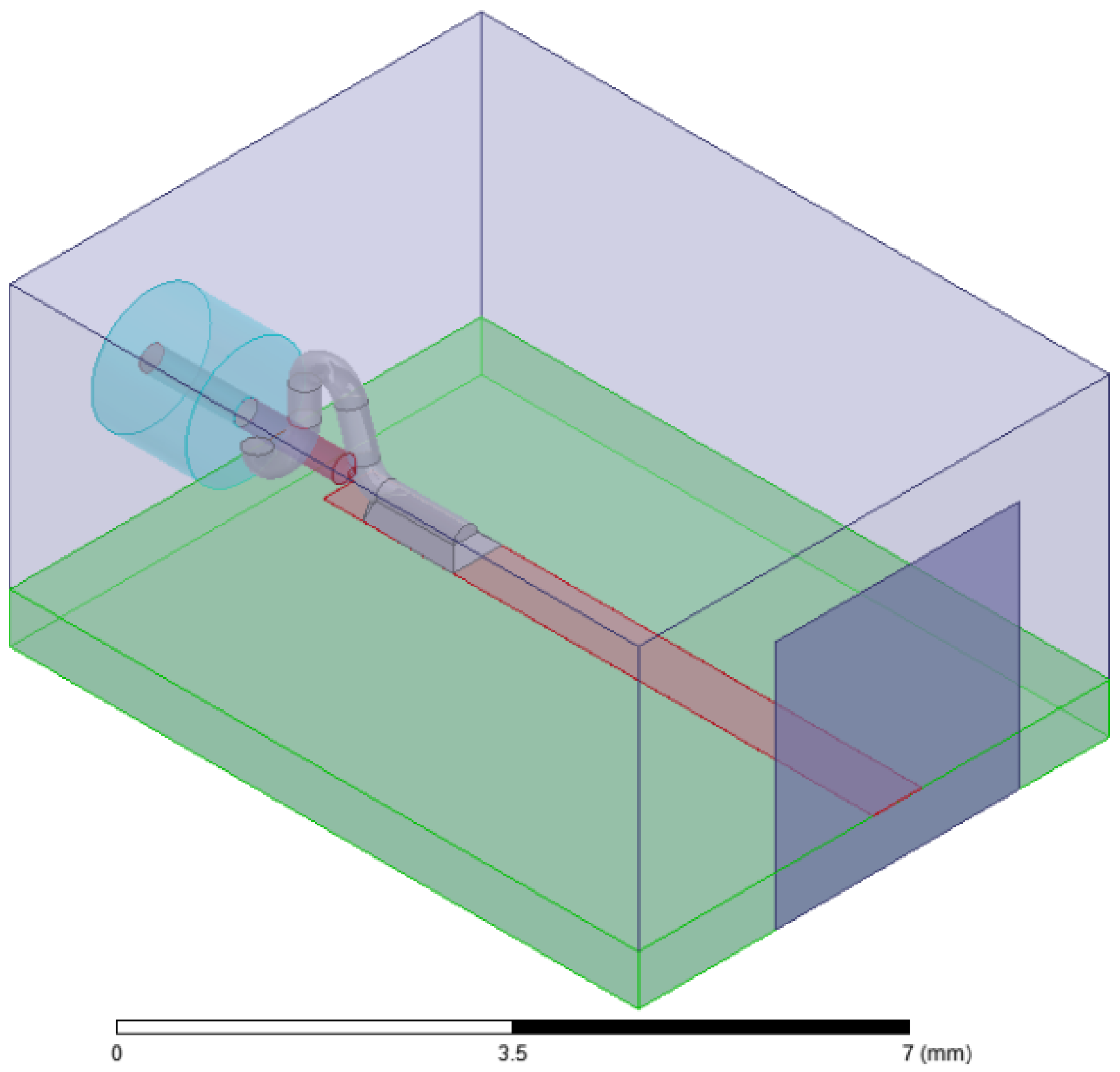
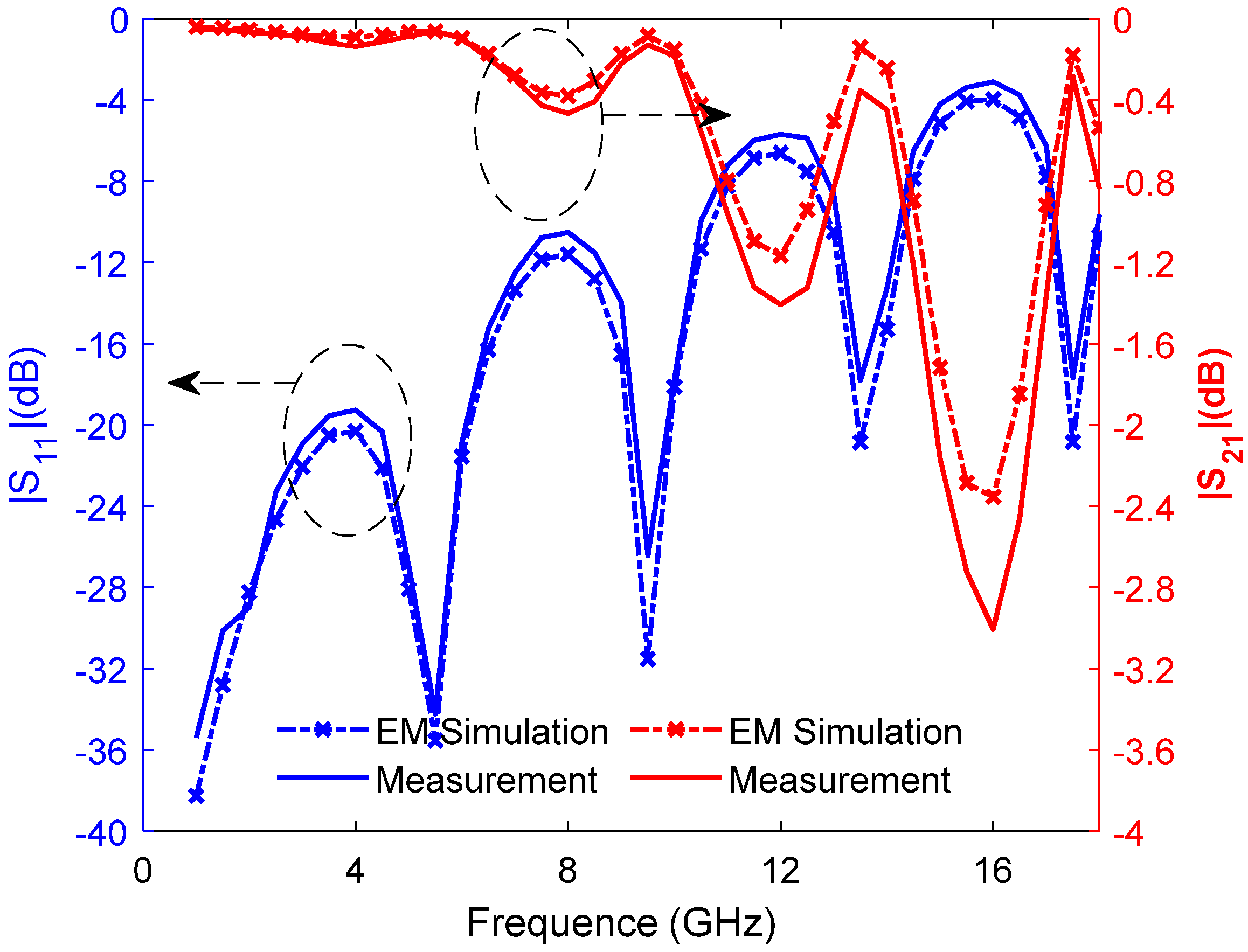
Section 2, the parametric mathematical representation of the FCWI configuration of the microwave circuit is obtained, and the three-dimensional structure electromagnetic simulation model is developed and verified. Section 3 presents the parameter identification process of electromechanical coupling in flexible interconnection, considering the interaction effect. An example calculation and discussion will be shown in Section 4. Finally, Section 5 concludes this work.

2. Characterization and Modeling of Flexible Interconnection

In order to identify the electromechanical coupling parameters of FCWI, it is necessary to accurately characterize the configuration of FCWI by parameterized mathematics, and further establish its three-dimensional structure electromagnetic simulation model [16,17,18].

2.1. Parameter Extraction of Interconnected Configurations

FCWI is mainly composed of glass dielectric, inner conductor, conductor wire, solder joint, conductor strip, dielectric substrate and ground plane. The conductor wire provides a flexible connection for interconnection through its own curved arch structure. In order to realize the parametric characterization of FCWI configuration, it is necessary to extract the geometric parameters affecting the configuration of flexible conductor wire interconnection, especially the structural parameters of irregular conductor wire. The extraction of interconnection configuration parameters is based on the principle that interconnection can be fully modeled. Figure 1 shows the structural composition and geometric parameters of this flexible interconnection. Table 1 describes the configuration characteristic parameters and dielectric properties of the flexible interconnection.

2.2. Characterization Modeling of FCWI

The establishment of the FCWI electromagnetic structure model depends on the accurate parametric characterization of the interconnection configuration. According to the principle of feature consistency, the interconnection discretization can be divided into seven sections: inner conductor, semicircle, vertical line, upper arc, oblique, lower arc, and horizontal line, as shown in Figure 2. The configuration characterization functions of each part of the FCWI are established in turn, as shown in Table 2.
Parameter α in Table 2 is the angle between the section of oblique line L a r 2 of the interconnection and the vertical direction z , and the detailed derivation is shown in the Appendix A.
The symbols a , b , and c in Table 2 can be calculated as follows:
{ a = ( R 1 + R 2 ) ( 1 sin α ) + T H e D 1 P e b = cos α ( R 1 + R 2 ) + R 1 L k e c = ( S g + L p e + L k e R 2 cos α ) ( H e + D 1 + P e + D 2 2 R 1 ( 1 sin α ) ) ( S g + L p e + R 1 ( 1 + cos α ) ) ( R 2 ( 1 sin α ) + D 2 2 + T ) .
Based on the parametric characterization method of FCWI configuration, the 3D electromagnetic simulation model of FCWI can be further established, which mainly includes a coaxial connector, microstrip line and flexible conductor wire. By using this electromagnetic structure simulation model, the influence mechanism of interconnection configuration parameters on the S parameter of signal transmission in the microwave circuit can be analyzed.

3. Identification of Electromechanical Coupling Parameters Considering Interaction Effects

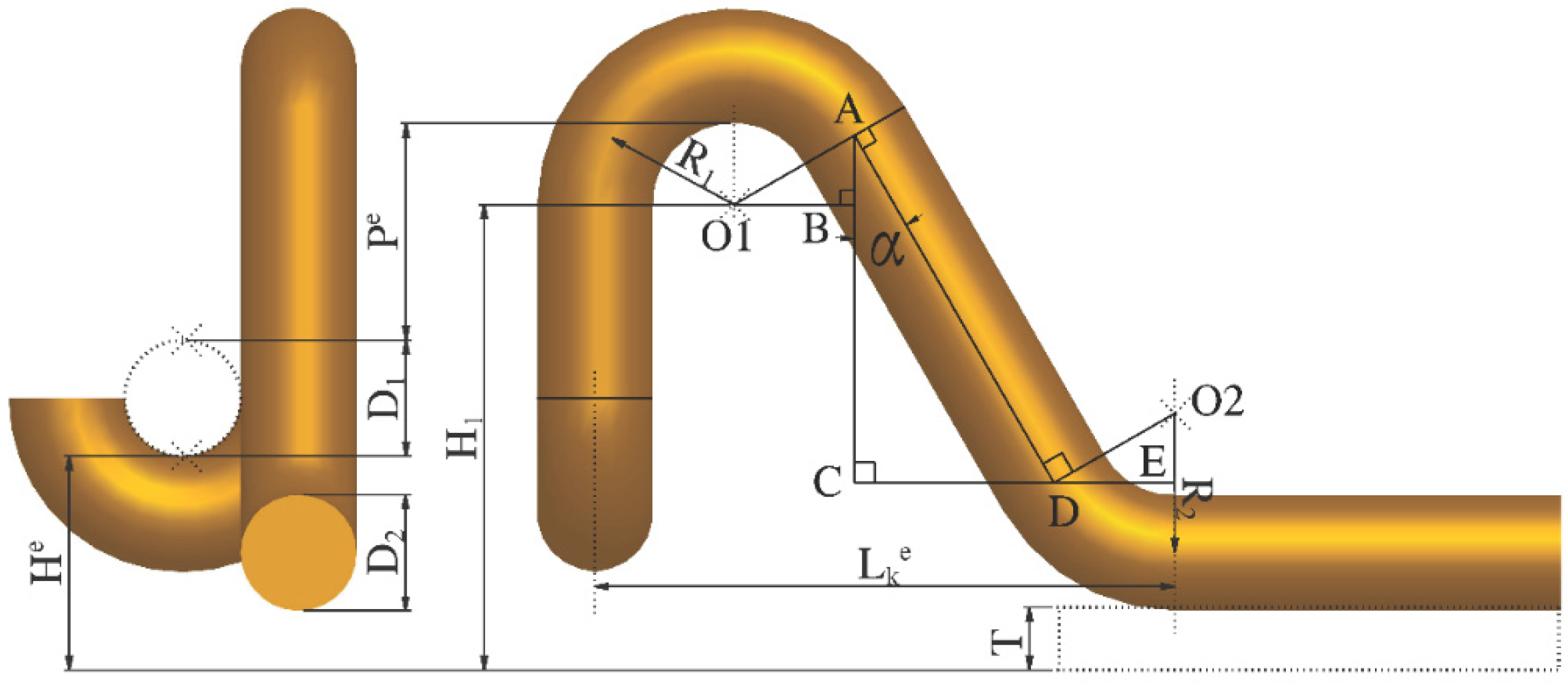
Through engineering research, combined with the analysis of the FCWI configuration characteristics, the six main geometric parameters, which have the most significant influence on the interconnection configuration, can be selected. The optimal value of the main geometric parameters in the variable interval can be determined, and the evaluation criterion of electromechanical coupling parameters can also be defined. In addition, the electromechanical coupling degree for the interconnected configuration parameters and their interaction is calculated. Finally, the electromechanical coupling parameter identification considering the interaction effect of parameters is realized [19,20].

3.1. Optimal Selection of Interconnect Configuration Parameter Values

According to the analysis of interconnection configuration characteristics and practical engineering investigation, six electromechanical coupling identification parameters and corresponding geometrically adjustable identification space are determined. Six-factors-seven-levels matrix is selected for electromechanical coupling identification parameters of the flexible interconnection configuration, as shown in Table 3. In order to facilitate research, the level values of each factor are selected at equal intervals. Here, the Six-factors-seven-levels matrix can be used to further generate orthogonal data for structural electromagnetic simulation.
In Table 3, ( S e ) v 1 ~ ( S e ) v 7 , ( H e ) v 1 ~ ( H e ) v 7 , ( P e ) v 1 ~ ( P e ) v 7 , ( L s e ) v 1 ~ ( L s e ) v 7 , ( L k e ) v 1 ~ ( L k e ) v 7 , and ( L p e ) v 1 ~ ( L p e ) v 7 are the corresponding parameters with seven levels. The factor level calculation formula in the table is:
X j m = δ X j _ + ( m 1 ) ( δ X j ¯ δ X j _ ) / 6 .
In the formula, j is the number of factors, m is the level number, X j m is the value of the m-th level parameter corresponding to the j-th factor, δ X j _ is the adjustable lower bound of the j-th factor parameter value, and δ X j ¯ is the j-th factor adjustable upper bound of parameter value.
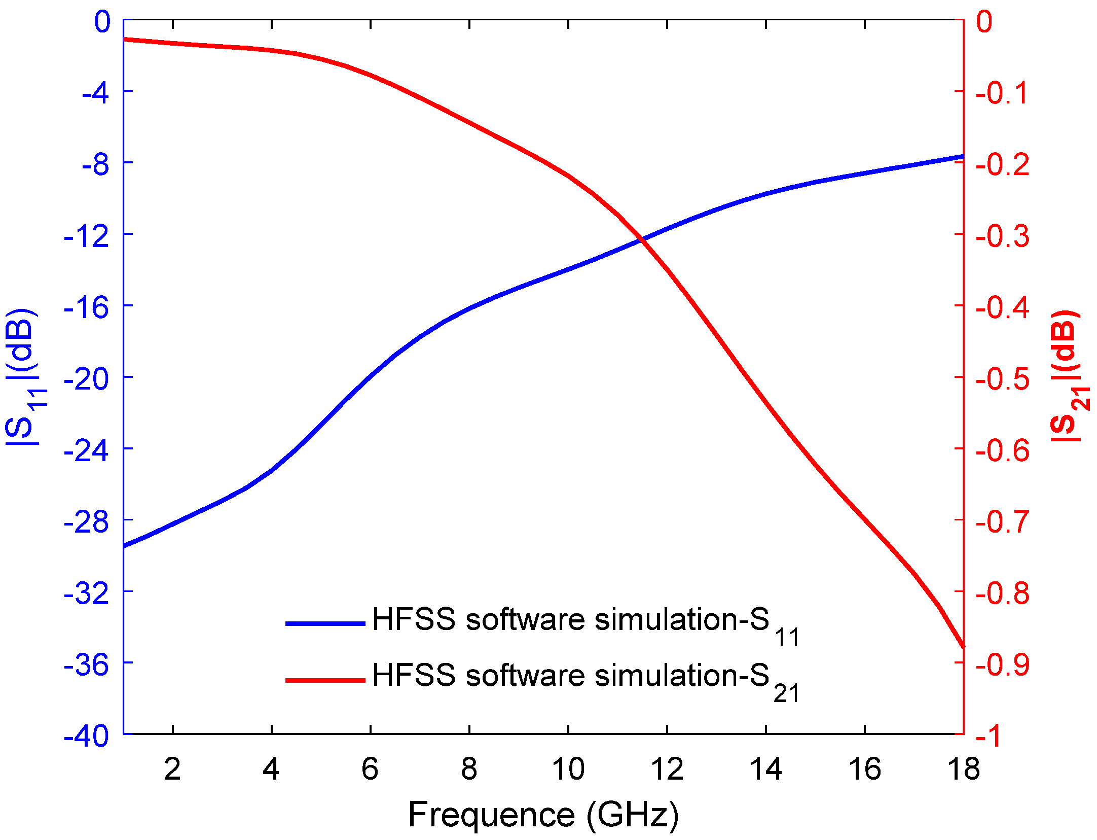
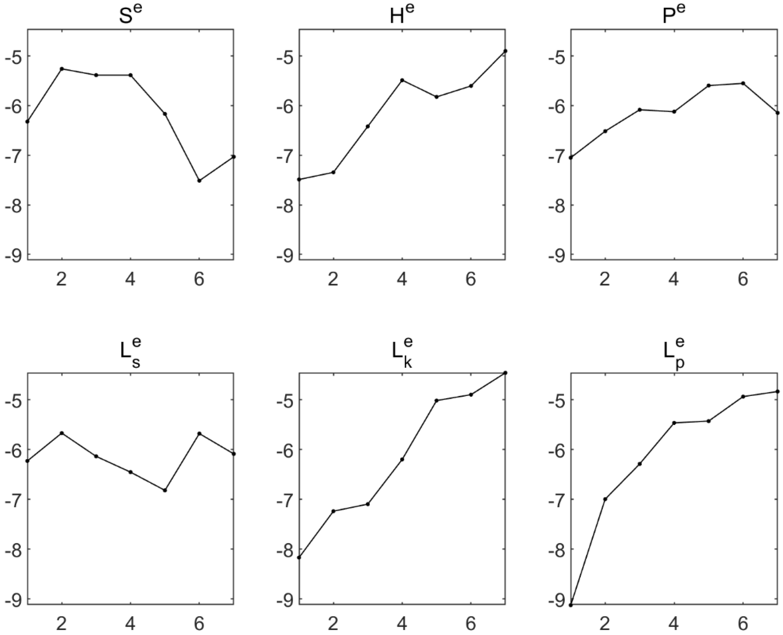
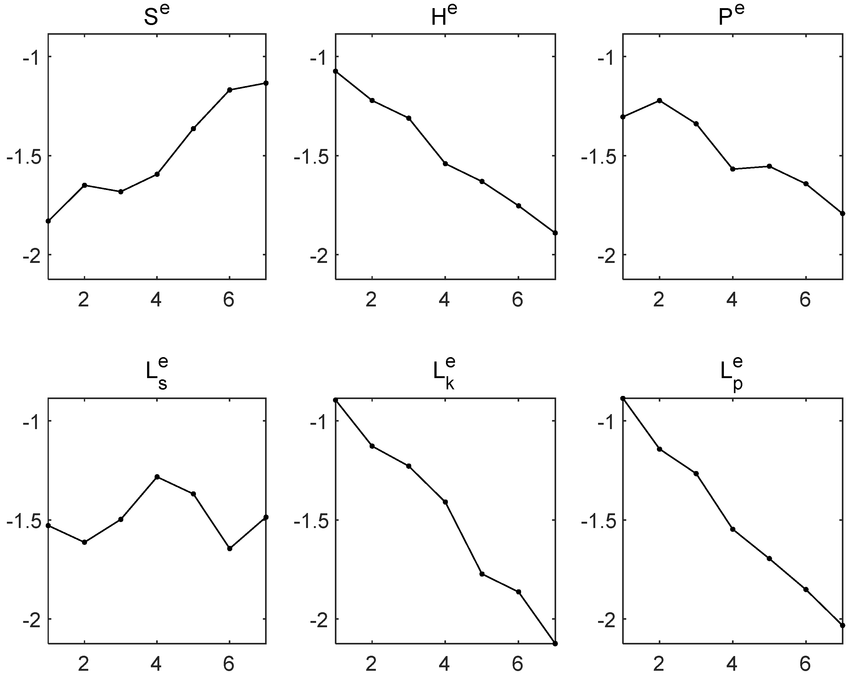
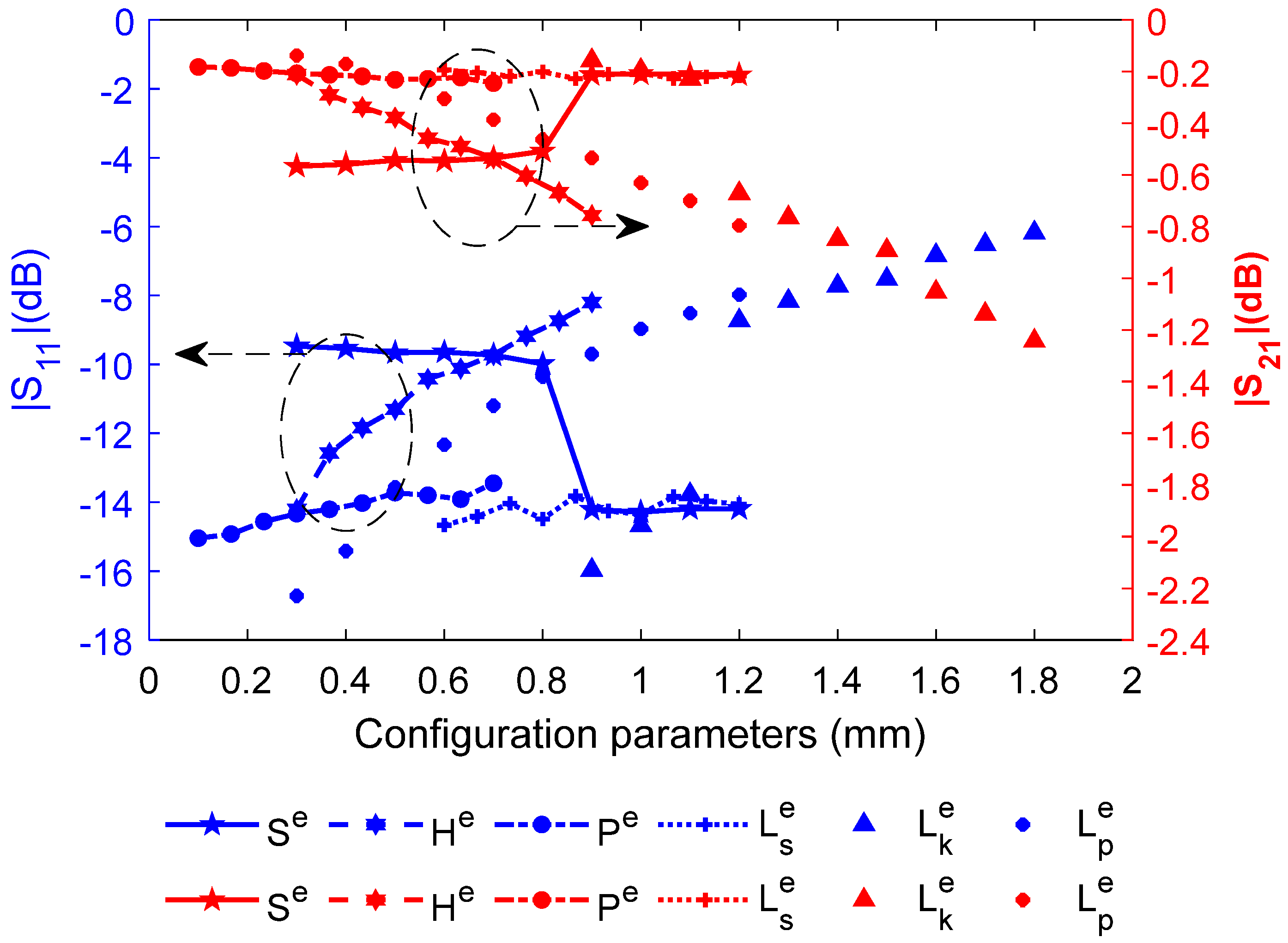
The scattering parameters | S 11 | and | S 21 | are selected as the signal transmission performance specifications, combined with three-dimensional electromagnetic full-wave simulation software, to design an orthogonal experiment between the FCWI configuration parameters and the signal transmission performance specifications. The extreme values of electrical parameters | S 11 | and | S 21 | and the corresponding electromechanical coupling parameter values of flexible interconnection were extracted by range analysis of orthogonal test results.
In order to select the optimal first level value for the FCWI geometric parameters, the minimum and maximum values of | S 11 | and | S 21 | of the flexible interconnection signal transmission performance are selected as the single targets for the optimal parameter level selection. Through multi-objective weighted summation, the optimal total objective function for level selection is further determined as:
Find Q = ( X s 1 ( X 1 ) , X s 1 ( X 2 ) , X s 1 ( X j ) ) Max ϕ ( X s 1 ( X j ) ) = w S 11 | S 11 ( X s 1 ( X j ) ) | | S 11 ( X d ) | + w S 21 | S 21 ( X d ) | | S 21 ( X s 1 ( X j ) ) | s . t . δ X j _ X s 1 ( X j ) δ X j ¯ ,
where X s 1 ( X j ) is the first level selection optimal for a single parameter of electromechanical coupling identification, X d is the design value combination of electromechanical coupling identification parameters, Q is the optimal level set of a single parameter, and w S 11 and w S 21 are the weight coefficients of electrical performance specifications | S 11 | and | S 21 | , respectively.
According to the overall goal, the optimal selection and calculation of the single configuration parameter level are performed one by one. If the minimum value of | S 11 | and the maximum value of | S 21 | corresponding to a configuration parameter have the same optimal level value, the overall configuration parameter level is X s 1 S 11 ( X j ) = X s 1 S 21 ( X j ) preferably.
By the same way, extract the second level value of the interconnect configuration parameters, select the maximum value of | S 11 | and the minimum value of | S 21 | as the single objective for the optimal selection of the level of the flexible interconnection parameter, and determine the overall objective function for the optimal selection of the parameter level as:
Find Q = ( X s 2 ( X 1 ) , X s 2 ( X 2 ) , X s 2 ( X j ) ) Min ϕ ( X s 2 ( X j ) ) = w S 11 | S 11 ( X s 2 ( X j ) ) | | S 11 ( X d ) | + w S 21 | S 21 ( X d ) | | S 21 ( X s 2 ( X j ) ) | s . t . δ X j _ X s 2 ( X j ) δ X j ¯ ,
where X s 2 ( X j ) is the second level of optimal selection of a single parameter for electromechanical coupling identification.
Select the optimal single parameter level in turn according to the overall goal. If the single parameter level of the interconnect configuration corresponding to the maximum value of | S 11 | and the minimum value of | S 21 | is the same, the overall level is X s 2 S 11 ( X j ) = X s 2 S 21 ( X j ) preferably.

3.2. Electromechanical Coupling Properties

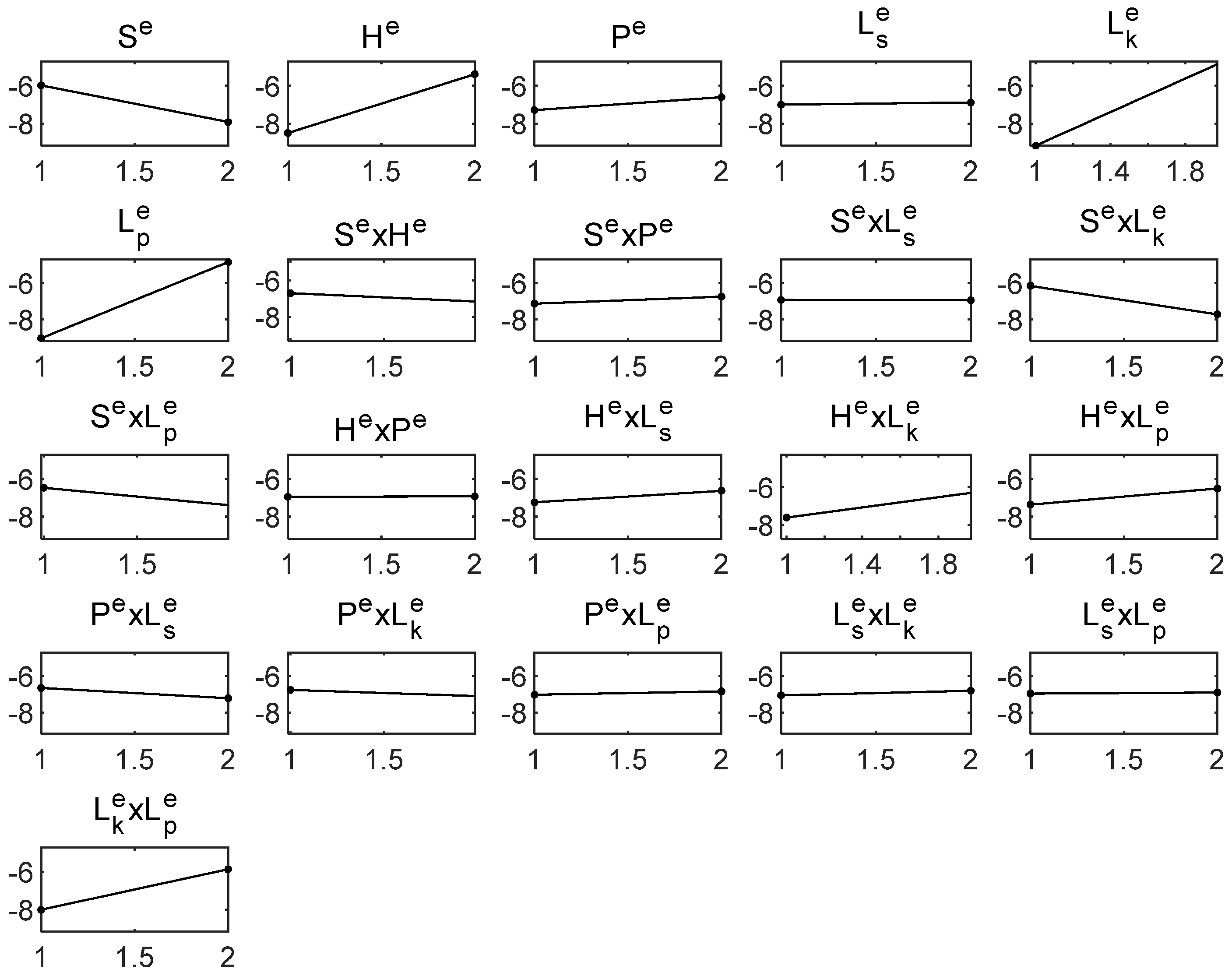
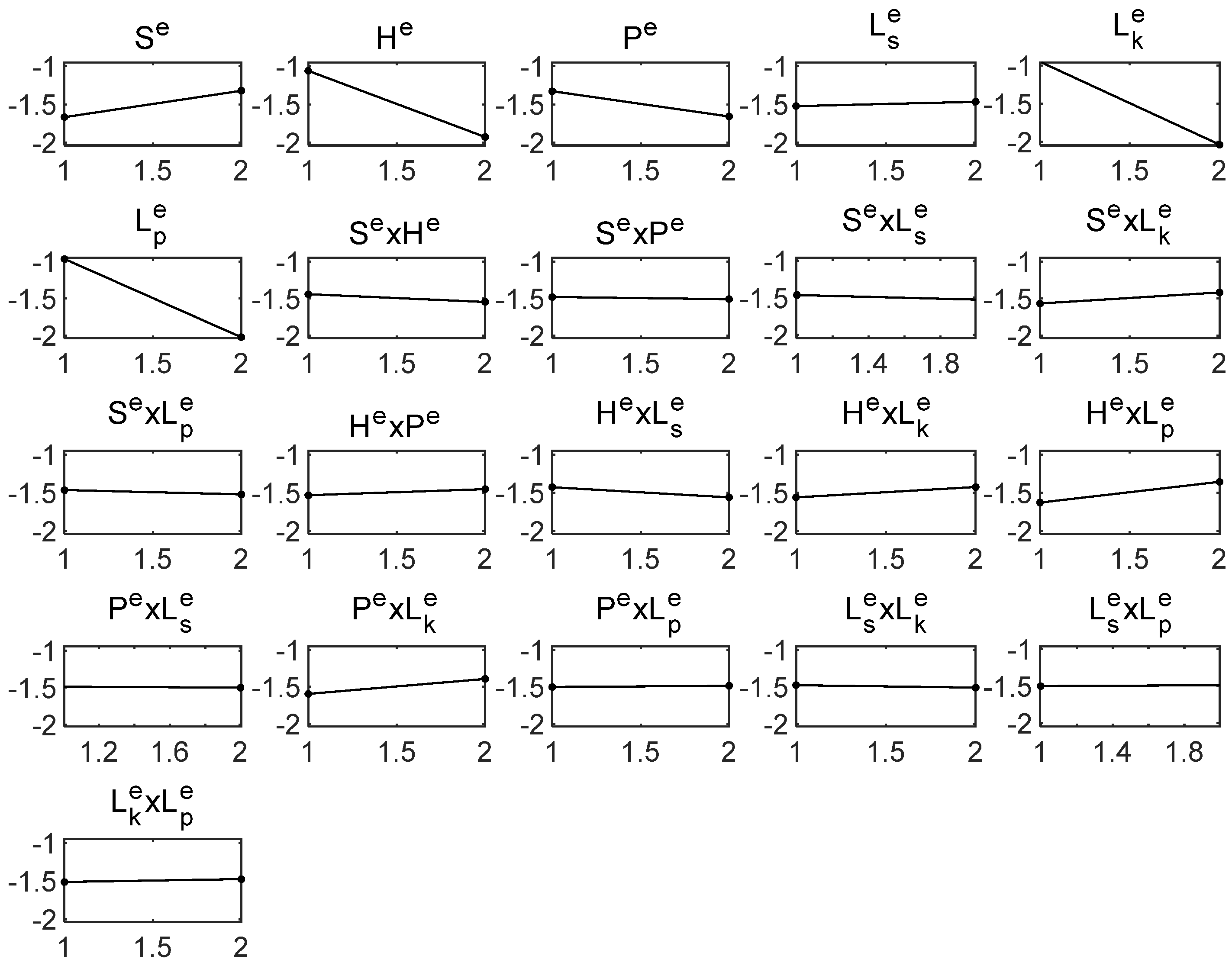
Generally, higher-order effects beyond the first-order interaction are small and the research is more complicated. Therefore, this research mainly focuses on single-factor effects and first-order interaction effects between factors, ignoring higher-order interaction effects. According to the optimal level of the FCWI electromechanical coupling identification parameters, combined with the analysis of the three-dimensional electromagnetic full-wave simulation software, the orthogonal experiment of the FCWI configuration parameters and the electrical performance specifications considering the interaction is designed.
Based on the analysis of variance of orthogonal experiment results considering the interaction effect, the criteria for judging the coupling property of the FCWI configuration and signal transmission are determined as follows:
{ C v ( X i ) C p 1 ( X i ) Strong   coupling C p 2 ( X i ) < C v ( X i ) C p 1 ( X i ) Weak   coupling C v ( X i ) < C p 2 ( X i ) Uncoupled ,
where
C v ( X i ) = w 1 F i S 11 + w 2 F i S 21 ,
C p 1 ( X i ) = w 1 F α 1 S 11 ( f i , f e ) + w 2 F α 1 S 21 ( f i , f e ) ,
C p 2 ( X i ) = w 1 F α 2 S 11 ( f i , f e ) + w 2 F α 2 S 21 ( f i , f e ) .
In the above formula, X i is the i-th factor considering the interaction effect, C v ( X i ) is the judgment value of coupling property for factor X i , C p 1 ( X i ) is the strong coupling boundary of factor X i , and C p 2 ( X i ) is a weak coupling boundary of factor X i . F i S 11 and F i S 21 are the ratio of the average difference square sum of the i-th factor effect to the average difference square sum of the error for the electrical property | S 11 | and | S 21 | , respectively. F α S 11 ( f i , f e ) and F α S 21 ( f i , f e ) are the critical values determined according to the freedom degree f i of the i-th factor, the freedom degree f e of error, F distribution and α quantile when | S 11 | and | S 21 | are used as electrical performance specifications, respectively, where α = { α 1 , α 2 } and α 1 < α 2 , w 1 and w 2 are the corresponding weight coefficients.
Based on the evaluation criterion of FCWI configuration and signal transmission coupling, the single factor coupling properties considering the interaction effect is determined by the following formula:
C r ( X ) = max { C r ( X ) , C r ( X 1 X 2 ) } ,
where C r ( X ) represents the single-factor coupling property and C r ( X 1 X 2 ) represents the interaction factor coupling property.
Based on the results of electrical performance range analysis of flexible interconnection considering the interaction effect, the coupling degree between flexible interconnection configuration and signal transmission is calculated as follows:
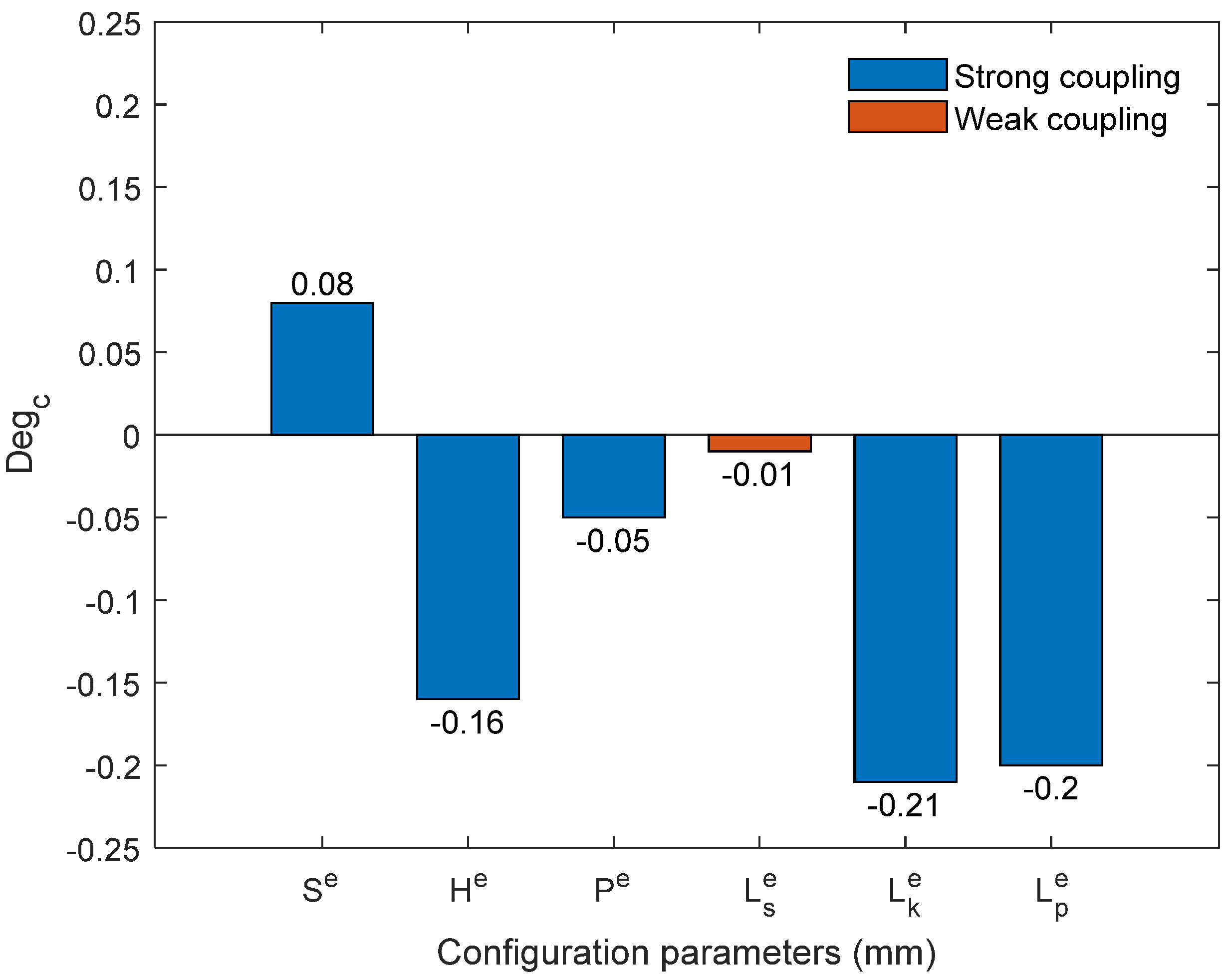
D e g C = w 1 R i S 11 / i = 1 v R i S 11 + w 2 R i S 21 / i = 1 v R i S 21 w 1 + w 2 .
In the above formula, R i S 11 and R i S 21 are the range values of the i-th factor for signal transmission | S 11 | and | S 21 | , respectively, and v is the sum of the number of strong coupling and weak coupling factors.
In this paper, the electromechanical coupling parameter is defined as the parameter whose coupling degree is not zero, namely the strong coupling parameter and the weak coupling parameter. Considering the influence of the interaction effect on the determination of the electromechanical coupling property of the parameter, the electromechanical coupling single parameter identification can be written as:
P a r C = P a r C ( X ) X 1 ( P a r C ( X 1 X 2 ) ) X 2 ( P a r C ( X 1 X 2 ) ) ,
where P a r C is a single factor electromechanical coupling parameter, P a r C ( X 1 X 2 ) is an interaction factor electromechanical coupling parameter, X is a single factor, X 1 X 2 is a factor first-order interaction term, X 1 is the first factor in the interaction term, and X 2 is the second factor in the interaction term.

4. Calculation and Discussion

This section selects an example about how to apply the proposed method of electromechanical coupling parameter identification for FCWI. Firstly, the electromagnetic model of three-dimensional structure of FCWI has been developed and validated. Secondly, the determination of electromechanical coupling property, the calculation of parameter coupling degree and the parameter identification of electromechanical coupling of flexible interconnected configuration are carried out, respectively. Finally, the identification results of electromechanical coupling parameters have been verified, and the electromechanical coupling properties of FCWI have been discussed.

4.1. Calculation of Electromechanical Coupling Parameters

4.1.1. Structural Electromagnetic Model

In this example, the application of microwave circuit interconnection in X-band T/R module is selected, and the 3D electromagnetic structure model of FCWI is established according to the characterization function derived in this paper. Then, the influence of interconnection configuration parameters on the signal transmission performance of the circuit can be studied. The specific geometric and physical parameters of the flexible interconnection are shown in Table 4.
Based on the interconnection parameters, the 3D structure electromagnetic model of interconnection has been established, as shown in Figure 3. The signal transmission performance of the flexible interconnection is further analyzed on the broadband 1–18GHz, as shown in Figure 4.
As can be seen from Figure 4, with the increase in signal transmission frequency, | S 11 | of FCWI gradually increases, signal transmission return loss gradually increases, | S 21 | gradually decreases, and signal transmission insertion loss gradually increases. When the frequency is 1 GHz, the return loss and insertion loss of FCWI are the minimum, and the signal transmission performance is the best. When the frequency is 18 GHz, the return loss and insertion loss of FCWI are the maximum, and the signal transmission performance is the worst. On the whole, with the increase in signal transmission frequency, the loss of FCWI configuration on signal transmission increases gradually.
In order to verify the accuracy of the three-dimensional structure electromagnetic model of FCWI, a prototype of FCWI-to-FCWI is manufactured and tested, as shown in Figure 5. The results of High Frequency Structure Simulator (HFSS) Electro Magnetic (EM) simulation are in good agreement with the measured results, which proves that the model has good accuracy, as can be seen in Figure 6.

4.1.2. Optimal Level of Interconnected Configuration Parameters

According to industrial investigation and analysis of flexible interconnection configuration characteristics, the design values of electromechanical coupling identification parameters and the adjustable identification space of six interconnected configurations are shown in Table 5.
Taking the identification parameters of the electromechanical coupling of the flexible interconnection configuration as the factor and, simultaneously, taking the electrical performance | S 11 | and | S 21 | as the indicators, the orthogonal experiment can be established. The trend chart of the interconnect configuration effect was obtained by range analysis of orthogonal experiment results, as shown in Figure 7 and Figure 8. The horizontal coordinates in the chart correspond to the level of interconnected configuration parameters, and the vertical coordinates are the | S 11 | and | S 21 | values in dB units.
Figure 7 and Figure 8 show that with the increase in interconnection configuration parameters H e , P e , L k e , L p e , the return loss | S 11 | and insertion loss | S 21 | of electromagnetic transmission gradually increase. With the increase in parameter S e , the return loss | S 11 | and insertion loss | S 21 | show a gradual decrease overall. With the increase in parameter L s e , the signal transmission loss | S 11 | and | S 21 | do not change significantly.
From the trend chart of the interconnect configuration effect in Figure 7 and Figure 8, the extreme levels of factors affecting the interconnection effect can be extracted, and then the level optimization function of the interconnect configuration parameters in this paper is further used to calculate the two optimal levels, as described in Table 6.

4.1.3. Electromechanical Coupling Parameters

Based on the selected level of electromechanical coupling identification parameters, a new orthogonal experiment with the flexible interconnection configuration parameter as the factor and the electrical performance | S 11 | and | S 21 | as the index considering the interaction effect is established. The trend chart of the range analysis is shown in Figure 9 and Figure 10, respectively.
Evaluating the electromechanical coupling characteristics and calculating the degree of coupling of the FCWI configuration parameters considering the interaction effects, the identification results of the electromechanical coupling parameter are illustrated in Table 7.
The single parameter and the interaction between the parameters can be divided into strong coupling, weak coupling and no coupling based on the calculation of electromechanical coupling degree. The value in the table represents the degree of electromechanical coupling; the larger the value, the stronger the electromechanical coupling. With the increase in electromechanical coupling parameter value, the + sign before the number indicates that the signal transmission | S 11 | and | S 21 | gradually become better, the - sign indicates that the signal transmission | S 11 | and | S 21 | gradually become worse, the ± sign indicates that the signal transmission | S 11 | gradually becomes better while | S 21 | gradually becomes worse, and ∓ means that the signal transmission | S 11 | gradually becomes worse while | S 21 | gradually becomes better.

4.2. Verification and Discussion of Electromechanical Coupling Characteristics

The main electromechanical coupling parameters of FCWI are identified and compared, as shown in Figure 11. It can be seen from the figure that the order of electromechanical coupling degree of flexible interconnection parameters is L k e > L p e > H e > S e > P e > L s e , which is the order of the influence between the FCWI configuration parameters and the signal transmission performance from strong to weak. The configuration parameters L k e , L p e , H e , S e , and P e are strong coupling parameters, and L s e is a weak coupling parameter. The configuration parameter S e is a positive coupling parameter, that is, the signal transmission performance gradually improves with the increase in configuration parameters. The configuration parameters L k e , L p e , H e , P e , and L s e are found to be negative coupling parameters, which means that the signal transmission performance gradually deteriorates with the increase in configuration parameters.
In order to verify the correctness of the electromechanical coupling parameter identification method proposed in this paper, the commercial software of HFSS is used for simulation comparison. The design values of the main configuration parameters of flexible interconnection are selected as the representatives of initial working conditions, and the corresponding electrical performance simulation results are obtained by sweeping the parameters one by one in the parameter identification space, as shown in Figure 12. The results show that the trend of the influence of parameters on electrical performance is kept consistent with that obtained by the proposed method of electromechanical coupling parameter identification in this paper. The same conclusion is also obtained by changing the initial sweeping value conditions of configuration parameters randomly, which proves the correctness of the proposed method.

5. Conclusions

In this paper, an identification method for electromechanical coupling parameters of FCWI in a microwave circuit considering the interaction effect has been proposed. In order to alleviate the reliability problems of the rigid interconnection in microwave circuits, a flexible conductor wire interconnection has been designed, and a three-dimensional structure electromagnetic model has been developed and verified. Then, the electromechanical coupling parameter identification of FCWI was studied, and the coupling property and coupling degree of interconnection configuration parameters to signal transmission loss were obtained. By the analysis of an example, the accuracy of this method has been verified. The result of electromechanical coupling identification is that the configuration parameters L k e , L p e , H e , S e , and P e are found to be strong coupling parameters, and L s e is found to be a weak coupling parameter. Configuration parameter S e is a positive coupling parameter, while L k e , L p e , H e , P e , and L s e are negative coupling parameters. The order of coupling degree of configuration parameters can be concluded as L k e > L p e > H e > S e > P e > L s e . This study can provide theoretical guidance for the optimal design and performance control of microwave circuit interconnection. The future research work is to establish an equivalent circuit model of this flexible conductor wire interconnection and study the comprehensive optimization design method of the interconnection considering the electromechanical and thermal properties.

Author Contributions

Conceptualization, J.T. and C.W.; methodology, J.T. and C.W.; software, J.T. and S.L.; validation, S.X.; formal analysis, S.X., L.Z., and J.L.; investigation, Z.W.; data curation, Z.W., K.Y., and R.L.; writing—original draft preparation, J.T., and S.L.; writing—review and editing, J.T., S.L., and S.X.; supervision, L.Z.; project administration, C.W.; funding acquisition, C.W. and J.L. All authors have read and agreed to the published version of the manuscript.

Funding

This work was supported by the National Natural Science Foundation of China under No. 51975447 and U1737211, the Natural Science Foundation of Shaanxi Province under No. 2018JZ5001, and the Youth Innovation Team of Shaanxi Universities under No. 201926.

Data Availability Statement

Not applicable.

Conflicts of Interest

The authors declare no conflict of interest.

Appendix A

According to the analysis of the characteristics of flexible interconnection configuration, it is necessary to calculate the inclination angle of the intermediate variable of conductor wire in order to realize the characterization of flexible interconnection configuration. The calculation of the inclination angle of conductor wire is shown in Figure A1.
Figure A1. Calculation of inclination angle parameters for conductor wire.
Electronics 10 00464 g0a1
If the distance between the upper surface of the dielectric substrate and the center of the upper arc of the conductor wire is H 1 , then the height of H 1 is calculated as follows:
H 1 = H e + D 1 + P e + D 2 2 R 1 ,
According to the geometric relations in ACD of the right triangle, there are:
tan α = sin α cos α = C D A C = L k R 1 ( 1 + cos α ) R 2 cos α R 1 sin α + H 1 R 2 ( 1 sin α ) D 2 / 2 T ,
sin 2 α + cos 2 α = 1 ,
Combined with the above formula, the inclination angle of the conductor wire can be calculated as:
α = arcsin { { 2 ( R 1 + R 2 ) ( H 1 R 2 ) + 4 ( R 1 + R 2 ) 2 ( H 1 R 2 ) 2 4 [ ( L k e R 1 ) 2 + ( H 1 R 2 ) 2 ] [ ( R 1 + R 2 ) 2 ( L k e R 1 ) 2 ] } 2 [ ( L k e R 1 ) 2 + ( H 1 R 2 ) 2 ] } .

References

  1. Herd, J.S.; Conway, M.D. The Evolution to Modern Phased Array Architectures. Proc. IEEE 2016, 104, 519–529. [Google Scholar] [CrossRef]
  2. Samanta, K.K. Ceramics for the Future: Advanced Millimeter-Wave Multilayer Multichip Module Integration and Packaging. IEEE Microw. Mag. 2018, 19, 22–35. [Google Scholar] [CrossRef]
  3. Kim, M.; Kong, S. Efficient Approach for Electrical Design and Analysis of High-Speed Interconnect in Integrated Circuit Packages. Electronics 2020, 9, 303. [Google Scholar] [CrossRef] [Green Version]
  4. Hassan, A.; Savaria, Y.; Sawan, M. Electronics and Packaging Intended for Emerging Harsh Environment Applications: A Review. IEEE Trans. Very Large Scale Integr. Syst. 2018, 26, 2085–2098. [Google Scholar] [CrossRef]
  5. Wang, Y.; Wang, C.; Lian, P.; Xue, S.; Liu, J.; Gao, W.; Shi, Y.; Wang, Z.; Yu, K.; Peng, X.; et al. Effect of Temperature on Electromagnetic Performance of Active Phased Array Antenna. Electronics 2020, 9, 1211. [Google Scholar] [CrossRef]
  6. Li, Y.; Srinath, P.K.M.; Goyal, D. A Review of Failure Analysis Methods for Advanced 3D Microelectronic Packages. J. Electron. Mater. 2016, 45, 116–124. [Google Scholar] [CrossRef]
  7. Kong, F.Z.; Yin, W.Y.; Mao, J.F.; Liu, Q. Electro-Thermo-Mechanical Characterizations of Various Wire Bonding Interconnects Illuminated by an Electromagnetic Pulse. IEEE Trans. Adv. Packag. 2010, 33, 729–737. [Google Scholar] [CrossRef]
  8. Wang, G.; Cheng, Z.; Wang, C. Computer Simulation of Three-dimensional Castellated Solder Joint Geometry in Surface Mount Technology. Model. Simul. Mater. Sci. Eng. 1998, 6, 557–565. [Google Scholar] [CrossRef]
  9. Feng, F.; Zhang, C.; Ma, J.; Zhang, Q.J. Parametric Modeling of EM Behavior of Microwave Components Using Combined Neural Networks and Pole-Residue-Based Transfer Functions. IEEE Trans. Microw. Theory Technol. 2016, 64, 60–77. [Google Scholar] [CrossRef]
  10. LaMeres, B.J.; McIntosh, C.; Abusultan, M. Novel 3-D Coaxial Interconnect System for Use in System-in-Package Applications. IEEE Trans. Adv. Packag. 2010, 33, 37–47. [Google Scholar] [CrossRef]
  11. Moravek, O.; Hoffmann, K.; Polivka, M.; Jelinek, L. Precise Measurement Using Coaxial-to-Microstrip Transition through Radiation Suppression. IEEE Trans. Microw. Theory Technol. 2013, 61, 2956–2965. [Google Scholar] [CrossRef]
  12. Cheng, J.C.; Li, E.S.; Chou, W.F.; Huang, K.L. Improving the High-Frequency Performance of Coaxial-to-Microstrip Transitions. IEEE Trans. Microw. Theory Technol. 2011, 59, 1468–1477. [Google Scholar] [CrossRef]
  13. Cai, N.; Zhou, Y.; Ye, Q.; Liu, G.; Wang, H.; Chen, X. IC Solder Joint Inspection via Robust Principle Component Analysis. IEEE Trans. Compon. Packag. Manuf. Technol. 2017, 7, 300–309. [Google Scholar] [CrossRef]
  14. Wang, Z.; Gao, J.; Flowers, G.T.; Yi, W.; Wu, Y.; Cheng, Z. The Impact of Connection Failure of Bonding Wire on Signal Transmission in Radio Frequency Circuits. IEEE Trans. Compon. Packag. Manuf. Technol. 2020, 10, 1729–1737. [Google Scholar] [CrossRef]
  15. Wang, Z.; Wang, L.; Yu, K.; Liu, S.; Wang, C. Equivalent Circuit Based Performance Coupling Analysis Method for Lead Wire Interconnection with Defects. Electronics 2020, 9, 642. [Google Scholar] [CrossRef]
  16. McPherson, J.W. Reliability Physics and Engineering: Time-to-Failure Modeling, 3rd ed.; Springer Press: New York, NY, USA, 2019; ISBN 978-3-319-93683-3. [Google Scholar]
  17. Edwards, T.C.; Steer, M.B. Foundations for Microstrip Circuit Design, 4th ed.; John Wiley & Sons Ltd. Press: Chichester, UK, 2016; ISBN 9781118936191. [Google Scholar]
  18. Lu, T.; Jin, J.M. Coupled Electrical-Thermal-Mechanical Simulation for the Reliability Analysis of Large-Scale 3-D Interconnects. IEEE Trans. Compon. Packag. Manuf. Technol. 2017, 7, 229–237. [Google Scholar] [CrossRef]
  19. Pratap, R.J.; Staiculescu, D.; Pinel, S.; Laskar, J.; May, G.S. Modeling and sensitivity analysis of circuit parameters for flip-chip interconnects using neural networks. IEEE Trans. Adv. Packag. 2005, 28, 71–78. [Google Scholar] [CrossRef]
  20. Wang, C.; Wang, Y.; Chen, Y.; Gao, W.; Xu, Q.; Wang, Z.; Liu, J.; Zhou, C.; Xu, W.; Zhong, J. Coupling Model and Electronic Compensation of Antenna-Radome System for Hypersonic Vehicle with Effect of High-Temperature Ablation. IEEE Trans. Antennas Propag. 2020, 68, 2340–2355. [Google Scholar] [CrossRef]
Figure 1. Composition and configuration parameterization of flexible conductor wire interconnection (FCWI).
Electronics 10 00464 g001
Figure 2. Discrete sections for FCWI configuration.
Electronics 10 00464 g002
Figure 3. Structure-electromagnetic analysis model for FCWI.
Electronics 10 00464 g003
Figure 4. Performance analysis of broadband signal transmission for FCWI.
Electronics 10 00464 g004
Figure 5. Photograph of the fabricated FCWI-to-FCWI.
Electronics 10 00464 g005
Figure 6. Comparisons of the measured scattering parameters with simulated results.
Electronics 10 00464 g006
Figure 7. Trend chart of return loss | S 11 | for electromechanical coupling identification parameters of flexible interconnection.
Electronics 10 00464 g007
Figure 8. Trend diagram of insertion loss | S 21 | for electromechanical coupling identification parameters of flexible interconnection.
Electronics 10 00464 g008
Figure 9. Return loss | S 11 | trend chart of flexible interconnection considering interaction effect.
Electronics 10 00464 g009
Figure 10. Insertion loss | S 21 | trend chart of flexible interconnection considering interaction effect.
Electronics 10 00464 g010
Figure 11. Comparison of electromechanical coupling characteristics of flexible interconnection.
Electronics 10 00464 g011
Figure 12. Comparison of single parameter simulation for interconnected configurations.
Electronics 10 00464 g012
Table 1. Configuration parameters and dielectric properties of FCWI.
ComponentsConfiguration CharacteristicsParameters
Conductor wireDiameter of conductor wire D 2
Distance from end of inner conductor to conductor connection S e
Distance from end of dielectric substrate to conductor connection L p e
Distance between upper arc of conductor wire and inner conductor P e
Conductor wire spacing L k e
Upper arc radius of conductor wire R 1
Lower arc radius of conductor wire R 2
Length of horizontal section of conductor wire L s e
Inner conductorInner conductor diameter D 1
Height of inner conductor to dielectric substrate H e
Glass dielectric 1Inner diameter of glass dielectric D 1
Gap between glass dielectric and dielectric substrate S g
Microstrip conductorWidth of microstrip conductor W
Thickness of microstrip conductor T
Dielectric substrate 2Thickness of dielectric substrate H s
1 Relative dielectric constant and tangent of loss angle of glass dielectric are ε 1 and θ 1 , respectively. 2 Relative dielectric constant and tangent of loss angle of dielectric substrate are ε 2 and θ 2 , respectively.
Table 2. Sectioned function characterization of FCWI configurations.
Geometric FeaturesCharacterization Function
Inner   conductor   ( L s t y ) { z = H e + D 2 2 , y [ 0 , S g + L p e + S e ] x = D 1 + D 2 2
Semicircle   ( L a r 1 ) { [ x ( D 1 + D 2 2 ) ] 2 + [ z ( H e + D 1 2 ) ] 2 = ( D 1 + D 2 2 ) 2 , x [ 0 , D 1 + D 2 ] y = S g + L p e
Vertical   line   ( L s t 1 ) { x = 0 , z [ H e + D 1 2 , H e + D 1 + P e + D 2 2 R 1 ] y = S g + L p e
Upper   arc   ( L a r 2 ) { [ y ( S g + L p e + R 1 ) ] 2 + [ z ( H e + D 1 + P e + D 2 2 R 1 ) ] 2 = R 1 2 x = 0 y [ S g + L p e , S g + L p e + R 1 ( 1 + cos α ) ]
Oblique   line   ( L s t 2 ) { a y + b z + c = 0 , y [ S g + L p e + R 1 ( 1 + cos α ) , S g + L p e + L k e R 2 cos α ] x = 0
Lower   arc   ( L a r 3 ) { [ y ( S g + L p e + L k e ) ] 2 + [ z ( T + D 2 2 + R 2 ) ] 2 = R 2 2 x = 0 y [ S g + L p e + L k e R 2 cos α , S g + L p e + L k e ]
Horizontal   line   ( L s t 3 ) { z = T + D 2 2 , y [ S g + L p e + L k e , S g + L p e + L k e + L s e ] x = 0
Table 3. Six-factors-seven-levels matrix table of flexible interconnected configuration parameters.
Factor S e H e P e L s e L k e L p e
Level
1 ( S e ) v 1 ( H e ) v 1 ( P e ) v 1 ( L s e ) v 1 ( L k e ) v 1 ( L p e ) v 1
2 ( S e ) v 2 ( H e ) v 2 ( P e ) v 2 ( L s e ) v 2 ( L k e ) v 2 ( L p e ) v 2
3 ( S e ) v 3 ( H e ) v 3 ( P e ) v 3 ( L s e ) v 3 ( L k e ) v 3 ( L p e ) v 3
4 ( S e ) v 4 ( H e ) v 4 ( P e ) v 4 ( L s e ) v 4 ( L k e ) v 4 ( L p e ) v 4
5 ( S e ) v 5 ( H e ) v 5 ( P e ) v 5 ( L s e ) v 5 ( L k e ) v 5 ( L p e ) v 5
6 ( S e ) v 6 ( H e ) v 6 ( P e ) v 6 ( L s e ) v 6 ( L k e ) v 6 ( L p e ) v 6
7 ( S e ) v 7 ( H e ) v 7 ( P e ) v 7 ( L s e ) v 7 ( L k e ) v 7 ( L p e ) v 7
Table 4. Geometric and physical parameters of flexible interconnection.
Geometric ParameterPhysical Parameters
Configuration CharacteristicsVariableDesign ValueRelative PermittivityTangent of Loss AngleMaterial
Diameter of conductor wire D 2 0.3N/AN/ACopper wire
Distance from end of inner conductor to conductor connection S e 0.9
Distance from end of dielectric substrate to conductor connection L p e 0.45
Distance between upper arc of conductor wire and inner conductor P e 0.4
Conductor wire spacing L k e 1.05
Upper arc radius of conductor wire R 1 0.3
Lower arc radius of conductor wire R 2 0.3
Length of horizontal section of conductor wire L s e 1
Inner conductor diameter D 1 0.3N/AN/A4J29
Height of inner conductor to dielectric substrate H e 0.3
Inner diameter of glass dielectric D 1 0.33.80.0004Quartz
Gap between glass dielectric and dielectric substrate S g 0
Width of microstrip conductor W 0.62N/AN/AGold
Thickness of microstrip conductor T 0.002
Thickness of dielectric substrate H s 0.6359.90.0020Ceramics
Table 5. Design variables, design values and identification space of flexible interconnection.
No.Identification ConfigurationDesign VariableDesign ValueIdentification Space
1Distance from end of inner conductor to conductor connection S e 0.9[0.3, 1.2]
2Height of inner conductor to dielectric substrate H e 0.3[0.3, 0.9]
3Distance between upper arc of conductor wire and inner conductor P e 0.4[0.1, 0.7]
4Length of horizontal section of conductor wire L s e 1[0.6, 1.2]
5Conductor wire spacing L k e 1.05[0.9, 1.8]
6Distance from end of dielectric substrate to conductor connection L p e 0.45[0.3, 1.2]
Table 6. Optimal levels of electromechanical coupling identification parameters for flexible interconnection.
Factor S e /mm H e /mm P e /mm L s e /mm L k e /mm L p e /mm
Level
10.30.30.20.90.90.3
21.050.90.61.11.81.2
Table 7. Electromechanical coupling parameter identification of flexible interconnection.
Strong CouplingWeak CouplingUncoupling
ParameterDegreeParameterDegreeParameterDegree
S e +0.08 L s e −0.01 S e × P e 0
H e −0.16 S e × L s e −0.01 P e × L s e 0
P e −0.05 S e × L p e ±0.02 P e × L p e 0
L k e −0.21 H e × P e ±0.01 L s e × L k e 0
L p e −0.20-- L s e × L p e 0
S e × H e ±0.02----
S e × L k e +0.05----
H e × L s e −0.03----
H e × L k e ±0.04----
H e × L p e 0.04----
P e × L k e 0.03----
L k e × L p e 0.05----
Publisher’s Note: MDPI stays neutral with regard to jurisdictional claims in published maps and institutional affiliations.

