1. Introduction
The absorption and radiation of light waves by materials make the loss of the system inevitable through the interaction process of light and material [
1]. By using the stimulated radiation of the gain medium or the parametric process of the nonlinear medium [
2,
3,
4], the energy loss or gain of the system can be compensated. The introduction of loss and gain in non-Hermitian optical structures provides more freedom for photon manipulation.
The concept of parity-time (PT) symmetry has been transplanted from quantum systems to non-Hermitian optical systems. It has become a research hotspot in recent years and has a broad application prospect in laser technology [
5,
6], optical sensing [
7], material engineering [
8], and other fields. In non-Hermitian systems, the eigenvalues of Hamiltonians are usually complex numbers. However, when the Hamiltonian satisfies the PT symmetry, the eigenvalues of the Hamiltonian may also be real numbers. The complex function of the refractive index for the PT optical system could be written as
, viz. the real component of the refractive indice presents the symmetrical distribution, while the imaginary component is anti-symmetric. The asterisk represents the complex conjugate operation. Compared with the uniform distribution of complex permittivity, the complex permittivity modulated by space or time makes the non-Hermitian optical system show many unique optical properties, such as optical invisibility [
9], one-way nonreflective transmission [
10,
11], electric field localization [
12,
13], and spectral singularity [
14,
15,
16], which opens a new path for the search and exploration of new photonic devices [
17,
18,
19]. The modulation of the complex permittivity includes the modulating of the real component and the imaginary component. It is found that spatial modulation of the real component of the permittivity could control the mode output, and the time modulation can be used to construct nonreciprocal devices such as optical isolators [
20]. The coherent-perfect-absorption−laser point (CPA−LP) [
21,
22,
23,
24,
25] and nonreciprocal amplification [
26] can be realized by modulating the imaginary part of the dielectric constant. CPA−LP is the reverse physics process of a laser, which could be utilized for an anti-laser, and it may completely absorb the electromagnetic wave with a specific frequency and waveform. Specifically, as two beams of coherent light waves with the same intensity incident on the upper and lower surfaces of the absorber, one can adjust the phase difference in the coherent lights to achieve the control of the absorption intensity from 0% to 100%. Instabilities of coherent perfect absorption in layered systems were analysed by alternating, amplifying, and absorbing media [
27]. CPA−LP, as a special solution of the broken phase in PT-symmetric systems [
28], may show more intuitive physical characteristics, which are of great significance to the study of non-Hermitian physics.
The PT-symmetric structures are special non-Hermitian systems. For quantum mechanics, if the Hamiltonian operator H and the parity time operator PT satisfy the reciprocity relation [H, PT] = 0, then the Hamiltonian is said to be PT-symmetric. The symbols T and P represent time and parity operators, respectively. In optical crystals, the condition of parity-time symmetry is equivalent to the existence of gain in one region of the system and the existence of equivalent loss in another region of symmetry. The scale of the loss and gain medium meeting should be the same size. The optical loss is easily doped and regulated within a large size range, but the optical gain can only be controlled within a small range. On the other hand, the loss/gain factor of the dielectric can be regulated by ion doping and two-wave nonlinear mixing. For example, the gain coefficient after beam coupling is significantly increased by two-wave mixing in Fe
3+-doped LiNbO
3 [
3] and Bi-doped Sn
2P
2S
6 [
29]. Inspired by the above studies, we here propose a PTX (parity-time-reciprocal scaling) symmetry dielectric structure. Based on PT symmetry, the structure increases the reciprocity symmetry of the space scale; that is, the optical gain size is reduced to 1/G of the optical loss size (G > 1), but at the same time, the optical gain coefficient is expanded to G times of the optical loss coefficient. Further, we explore CPA−LPs and their related characteristics in PTX-symmetric dielectric structures.
In this study, compound systems are synthesized, which contain two kinds of dielectric slabs A and B with different refractive indices. The loss/gain factor of dielectrics and the thickness of slabs A and B are modulated to satisfy parity-time-reciprocal scaling (PTX) symmetry. We first investigate multiple CPA−LPs arising from the parameter space consisting of the loss/gain factor and incident wavelength. Subsequently, regulation of the CPA−LPs is explored through the incident angle. Then, phase-shift characteristics of light waves at CPA−LPs are presented as well. Our research provides a theoretical or experimental project for designing multi-wavelength tunable lasers or half wave phase shifters.
2. Synthesis of PTX-Symmetric Dielectric Structure
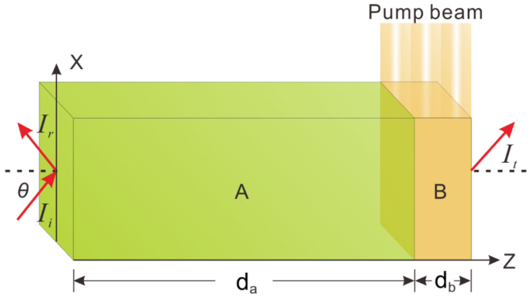
The proposed geometrical structure is given in
Figure 1. The symbols A and B denote two dielectric slabs with different refractive indices. Their geometrical thicknesses are denoted by
da and
db. The indices A and B are given by:
na =
nar +
i*nai,
nb =
nbr +
i*nbi, where
nar and
nbr, respectively, represent the real part
nai and the imaginary part
nbi and
i is the imaginary unit. The incident, reflected, and transmitted light beams are denoted by the symbols
Ii,
Ir, and
It, respectively. The incident angle is denoted by
θ which represents the included angle between the incident beam and the horizontal direction (i.e., Z-axis). The host material of A can be set as LiNbO
3. Weak optical loss can be realized by doping iron ions (Fe
2+) into the dielectric slab A and one can choose ion-doped LiNbO
3 for the optical loss dielectric A [
3]. The host material of slab B may be SiO
2 and the optical gain coefficient is controlled by Er
3+ doping in slab B along with the intensity regulation of the external pump beam. The refractive indices of materials and the thicknesses of slabs of the system are adjusted subtly, and finally, the entire dielectric structure meets the PTX symmetry.
The parameter
z is the spatial position coordinate and the refractive index function of a composite system that satisfies the equation:
n(
z) =
n*(−
z); then, the system follows PT-symmetry. The refractive index function is written in conjugate form, that is,
n(
z) =
nr(
z) +
i*
ni(
z). In practice, the real component and imaginary component of the refractive index in materials need to be adjusted concurrently, so that the real refractive index meets even symmetry, viz.
nr(z) =
nr(−
z), while the imaginary refractive index satisfies odd symmetry, viz.
ni(
z) = −
ni(−
z). The positive imaginary part of the index value represents the optics gain of the material, which can be realized by nonlinear two-wave mixing or ion doping. It shows that the optical gain in a broad-area semiconductor amplifier can be realized by the two-wave mixing, in which a pump beam and a signal beam with different frequencies, both a moving phase grating and a moving gain grating, are induced in the amplifier [
30]. The optical gain is further provided through two-wave mixing in Fe
3+-doped LiNbO
3 using the material’s photorefractive nonlinearity, while optical loss is induced by Fe
2+-doping [
3]. Otherwise, optical gain enhancements in Si nanocrystals via hydrogenation and Ce
3+ ion doping and Bi-doped Sn
2P
2S
6 crystals are through a two-beam coupling [
29,
31]. The coupling gain is induced by a higher effective electro-optic coefficient and an increase in the trap density compared with values in these pure nanocrystals or crystals. The negative imaginary refractive index component represents the optical loss in the system, and the optical loss can be realized by ion doping.
Compared with PT symmetry, the PTX-symmetric condition of the dielectric structure demands the function of the refractive index to meet the equations: da = db/, nar = nb and nai / = nbi. The parameter G is the scale transformation coefficient. For LiNbO3, the real part of the refractive index is nar = nbr = 2.22, and the imaginary part is nai = 0.01*q and nbi = −0.1*q, respectively. The mark q is called the loss/gain factor of optical media. The dielectric thicknesses are da = 5 μm and db = 0.5 μm. Here the scale transformation coefficient is set as G = 10.
For a transverse magnetic (TM) wave at the two ports of a layer, the electric and magnetic fields can be interconnected by the transfer matrix method (TMM) [
32,
33].
The symbol is
φj = 2
πnldlcos
l/
λ. The parameter
dl is the thickness of dielectric and
θl is the angle of incidence. The symbol
ηl = (ε
0ε
r)
1/2/[(μ
0μ
r)
1/2cos
θl]. Then, the electric and magnetic fields at the first input port and last output port can be expressed as
Consequently, the transmission coefficient
t and reflection coefficient
r can be obtained as
and
where
η0 =
ηk = (ε
0/μ
0)
1/2/cos
θ. The parameter
η0 is the admittance in vacuum. The transmittance
T of light beam and the reflectance
R can be obtained by
T =
tt* and
R =
rr*, respectively.
3. Multiple CPA−LPs and Half Wave Phase Shift
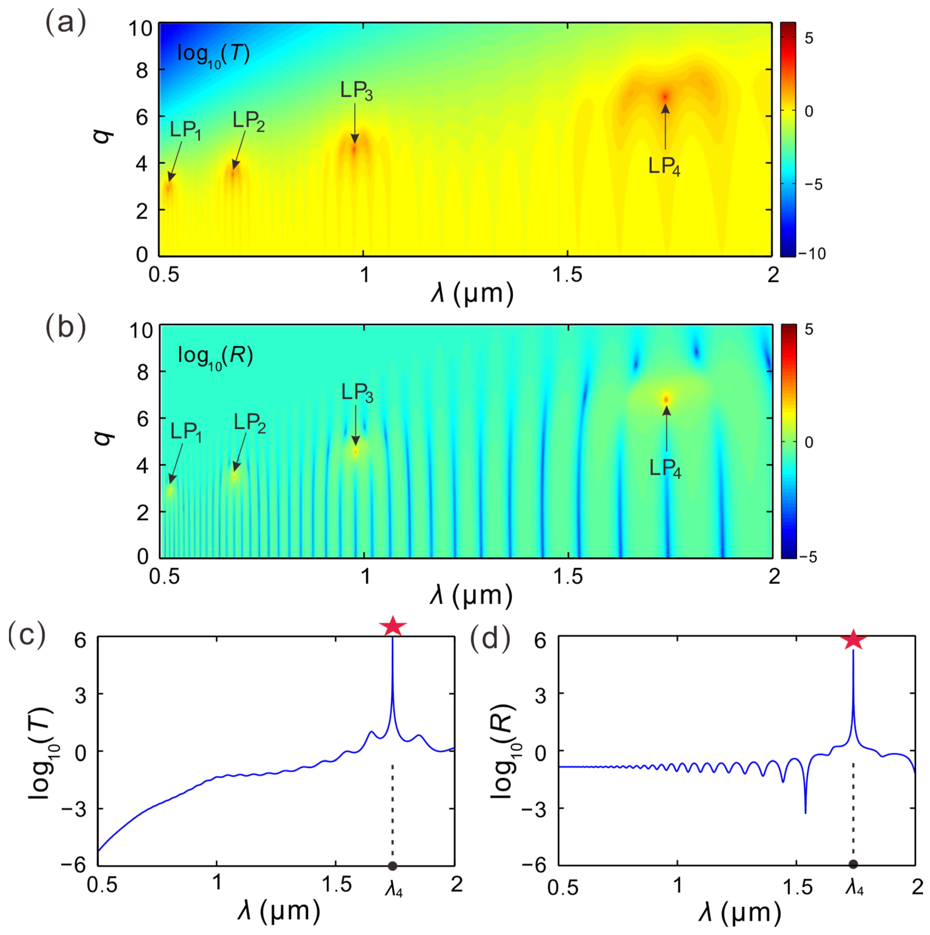
The transmittivity log
10(
T) in parameter space is described in
Figure 2a. The parameters space is constituted by the loss/gain factor and the incident wavelength. The transverse magnetic wave is propagating along the Z-axis in the PTX-symmetric structure and the angle of incidence is fixed by
θ = 0°. The logarithm log
10(
T) of the light transmittance
T can be aimed at enhancing the contrast ratio. By modulating the values of
λ in the range of [0.5 μm, 2 μm] and
q in the range of [0, 10] synchronously, we could find the transmission extreme points in parameters space. The maximum transmitted point is commonly known as this CPA−LP, denoted by the symbol LP. Briefly, these four laser points are located at LP
1 [
λ1 = 0.5198 μm,
q1 = 2.8529], LP
2 [
λ2 = 0.6785,
q2 = 3.4835], LP
3 [
λ3 = 0.9765 μm,
q3 = 4.5646], and LP
4 [
λ4 = 1.7393 μm,
q4 = 6.8168], and the corresponding transmittance values at these CPA−LPs are
T1 = 6.6405 × 10
3,
T2 = 2.7102 × 10
4,
T3 = 4.162 × 10
4, and
T4 = 9.7791 × 10
5, respectively.
Figure 2b explores the reflection spectrum log
10(
R) in parameters space. We mark the four dark orange dots as LP
1, LP
2, LP
3 and LP
4, representing four points with the maximum value of
R. The positions of these four poles are exactly at [
λ1 = 0.5198 μm,
q1 = 2.8529], [
λ2 = 0.6785 μm,
q2 = 3.4835], [
λ3 = 0.9765 μm,
q3 = 4.5646], and [
λ4 = 1.7393 μm,
q4 = 6.8168], viz. the four CPA−LPs. The corresponding values of
R for these four poles are
R1 = 1.0053 × 10
3,
R2 = 4.1495 × 10
3,
R3 = 6.8375 × 10
3, and
R4 = 1.8268 × 10
5, respectively.
To further prove the resonance characteristics of the CPA−LPs, we focus on one of the laser points to investigate its optical spectrum.
Figure 2c describes the spectrum of transmission light waves for the parameter of
q = 6.8168. The parameter
q = 6.8168 is exactly equal to the corresponding loss/gain factor of LP
4. The transmittivity of the light beams changes with the increase in the incident wavelength, and one can find that a sharp transmission peak appears in the spectrum of transmission beams, which is indicated by a red asterisk (☆). The value of this transmission peak is log
10(
T) = 5.9903, and correspondingly, the wavelength of incidence is fixed by
λ = 1.7393 μm, which also happens to be
λ4. The transmittance of this peak log
10(
T) = 5.9903 = log
10(
T4) identifies with the transmittance at LP
4. The transmittivity roughly increases with the augment of the incidence wavelength as
λ ≤ 1.7393 μm. The transmitted intensity of light beams has been greatly improved as the incident wavelength tends to LP
4 from the left side. As the value is
λ > 1.7393 μm, the transmittivity decreases with the rise in the incident wavelength, while the transmitted intensity declines dramatically when the incident wavelength expands from the right of LP
4. Otherwise, the transmission spectrum curve is asymmetric to the CPA−LP of LP
4.
Figure 2d studies the relationship between the incident wavelength and the reflectance of the light beam for the value of
q = 6.8168. It can be found that the reflectance of the light waves changes with the wavelength of incidence. At
λ = 1.7393 μm, there is a reflection peak, marked with a red asterisk (☆) as well. The peak value of reflectance is taken as the logarithm log
10 (
R) = 5.2617 = log
10 (
R4), so the value is exactly equal to the reflectance at LP
4. Similarly, by adjusting the incident wavelength, the reflectivity of the light waves changes violently near the LP
4. The reflectance changes relatively gently as the incident wavelength moves away from LP
4 on both sides.
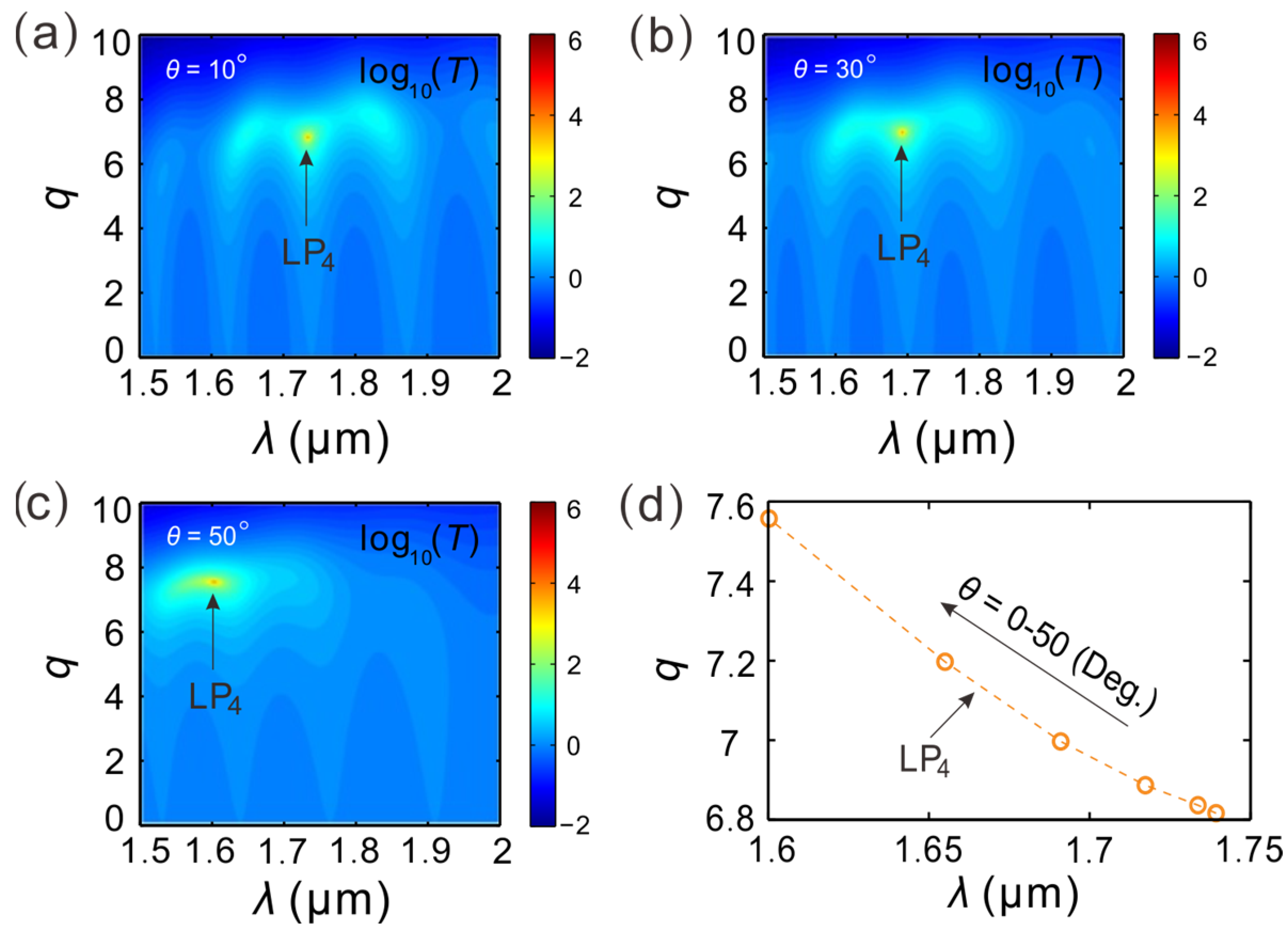
Furthermore, one can change the incident angle, and the other parameters remain unchanged. Along the Z-axis a transverse magnetic wave propagates in the PTX-symmetric dielectrics structure as the incidence angle is
θ = 0°.
Figure 3a provides the transmittivity of light waves around LP
4 as
θ = 10°. The CPA−LP (LP
4) appears at [
λ4 = 1.7337 μm,
q4 = 6.8368] in parameter space. The transmittivity at this CPA−LP (LP
4) is
T = 2.0128 × 10
5. For the value of incident angle
θ = 30°, the CPA−LP (LP
4) moves to [
λ4 = 1.691,
q4 = 6.997] and its transmittance is
T = 4.1908 × 10
6 as provided in
Figure 3b. Increasing the angle of incidence to 50°, the position of the CPA−LP (LP
4) is located at [
λ4 = 1.6003 μm,
q4 = 7.5576], as shown in
Figure 3c, and the corresponding transmittance is
T = 1.0174 × 10
6.
Changing the angle of incidence from the value of 0° to 60°,
Figure 3d shows the relationship between the position of this CPA−LP (LP
4) in parameter space and the incidence angle. One can see that with the augment of the angle value of incidence, LP
4 moves to the upper left of the parameter space, viz. the corresponding wavelength of the laser decreases, and the loss/gain factor grows. In a similar way, the corresponding wavelengths of the other laser points of LP
1, LP
2, and LP
3 may change with the incidence angle as well. If the incident angle of the light wave changes, the position of the corresponding laser point in parameter space will change accordingly, that is, by changing the value of the incidence angle, the corresponding laser wavelength may be tuned.
In the parameter space constituted by the incident light wavelength and the loss/gain factor, the PTX-symmetric dielectric structure supports multi-wavelength laser points. Multi-wavelength laser points correspond to the maximum points of transmittance and reflectance, which could be utilized for obtaining ideal multi-wavelength lasers. The wavelengths of the laser correspond to the wavelength values at these multi-wavelength laser points. The multi-wavelengths of the laser can be flexibly adjusted by the value of the incidence angle. Compared with PT-symmetric aperiodic photonic crystals, which also are used for realizing multi-wavelength laser, the PTX-symmetric dielectric proposed here has a simple structure. However, the reduction in the size of the gain material in multi-wavelength lasers is at the cost of increasing the gain coefficient of the material.
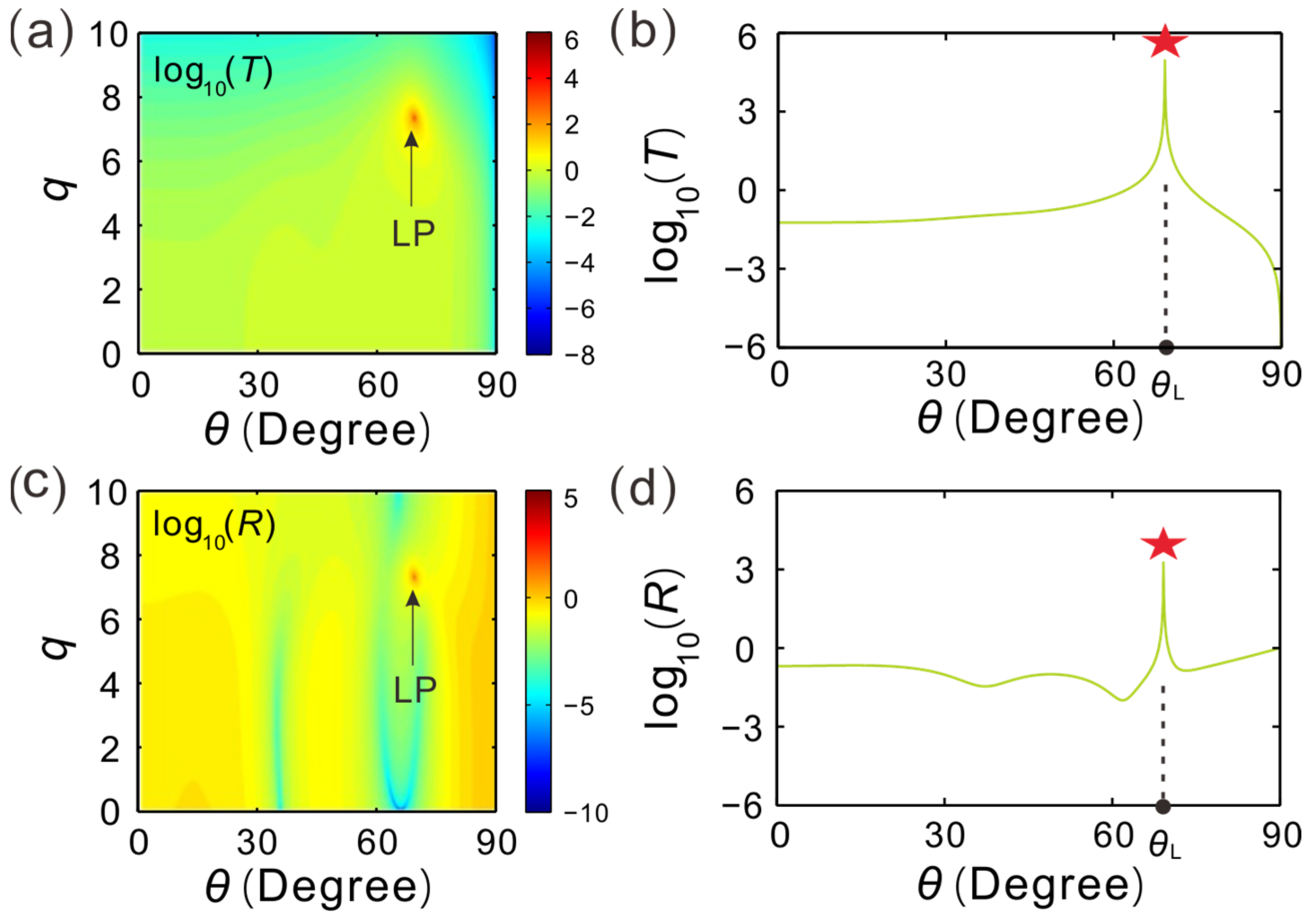
For a fixed incident wavelength, the dependence of the CPA−LP on the direction of the reflected light wave in the PTX-symmetric dielectric structure is discussed here.
Figure 4a demonstrates the intensity transmitted light versus the loss/gain factor and the incident angle. One could find that there is a CAP−LP in the parameters space. The according parameters of this CAP−LP are given by the incident angle of
θ = 69.175°, the loss/gain factor
q = 7.3417, and the maximum transmittivity of
T = 8.9702 × 10
4.
For the loss/gain factor value
q = 7.3417,
Figure 4b describes the corresponding transmission spectrum changing with the incidence angle. The transmittance changes with the incidence angle. At
θ = 69.175°, there is a sharp transmission peak marked with a red asterisk (☆). At the labeled asterisk, the maximum value is log
10(
T) = 4.9528 = log
10(
TL), which exactly equates to the relevant value of transmittance for the laser point LP, as shown in
Figure 4a. The transmission intensity increases slowly with the increase in the incident angle for
θ ≤ 69.175°, while for
θ > 69.175°, the transmission intensity decreases rapidly with the rise in the incidence angle. As the incident angle reaches the peak from the right or the left sides of this laser point LP, the transmission intensity could be greatly improved. Therefore, one can modulate the parameters of the laser point LP through the loss/gain factor and the incidence angle.
Figure 4c provides the reflectance of light waves varying with the incidence angle in parameters space. In order to increase the contrast, the logarithm log
10 (
R) of the light wave reflectance
R is also taken in simulations. There is one LP appearing in the quantitative value range of parameters space, and its reflectance is extremely high, with a value of
RL = 1.8214 × 10
3. For a fixed quantity of the loss/gain factor
q = 7.3417, the corresponding reflection spectrum for light waves is described in
Figure 4d. Obviously, the reflectance increases as the incident angle changes around
θ = 69.175° =
θL, and the reflectance reaches the maximum value at
θL marked with a red asterisk (☆). The reflectance at this point is log
10(
R) = 3.2604 = log
10(
RL). In the same way, the reflectivity of light waves changes dramatically near this CPA−LP. When the incident angle of the light waves is far from the peak on both sides, the reflectance change is relatively flat. In conclusion, for the PTX-symmetric dielectric structure proposed here, the CPA−LP is precisely located at the pole of the transmitted light beam or the reflected light beam.
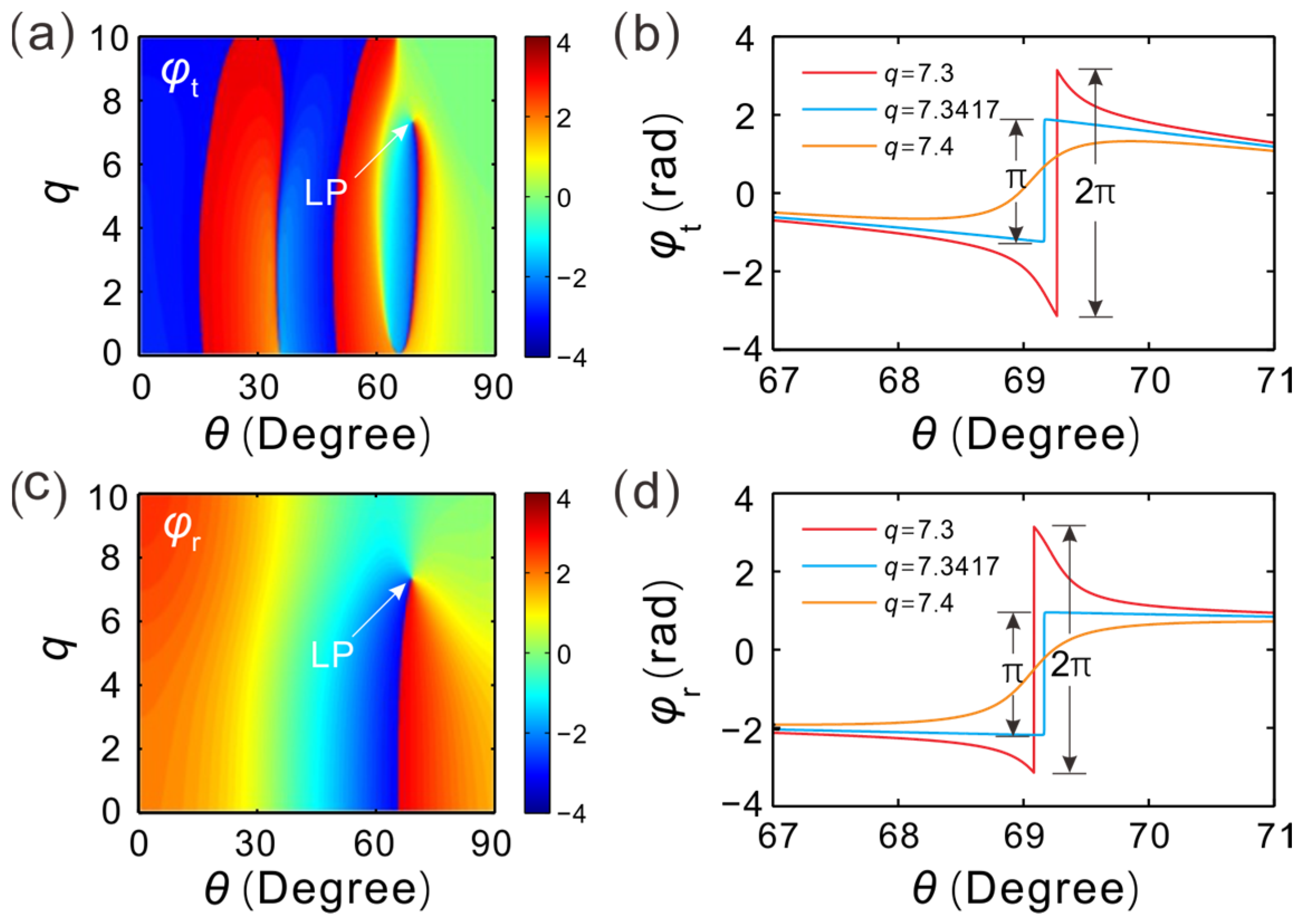
Generally, the transmission coefficient can be expressed as t = Eo/Ei, where Ei denotes the input electric field strength, while Eo represents the transmission electric field strength, both of which are complex. Further, the transmission coefficient is written in the form of the complex index, t = |t|exp(iφt), Eo = |Eo|exp(iφo), and Ei = |Ei|exp(iφi). From this, we can obtain Eo = t*Ei = |t||Ei|exp[i(φt + φi)], viz. the phase φo = φt + φi of the transmitted electric field. Similarly, the phase φo = φr + φi of the reflected electric field can be obtained. That is to say, the phase of the electric field is closely related to the reflection coefficient phase and the transmission coefficient phase. Finally, the phase of the electric field can be adjusted by modulating the reflection coefficient phase or the transmission coefficient phase.
For a fixed incident wavelength
λ = 1.31 μm, the transmission coefficient phase of the light waves in parameters space is formed by the loss/gain coefficient and the incident angle is demonstrated in
Figure 5a. One could find that the CPA−LP is located at [
θL = 69.175°,
qL = 7.3417] and the transmission coefficient phase
φt is singular at the CPA−LP. This means that near the CPA−LP, the phase of transmission coefficient is very sensitive to the incident angle and the loss/gain factor. If the incident angle undergoes a minor change, the transmission coefficient phase will vary dramatically.
Figure 5b provides the transmission coefficient phase varying with the incident angle. For demonstrating the change in the transmission coefficient phase, we here take three specific values of the loss/gain factor to demonstrate. The incident wavelength is provided by
λ = 1.31 μm. The parameter value
q = 7.3417 is just equal to the loss/gain factor of the CPA−LP. One of the other two parameters is greater than
q = 7.3417 and the other is less than
q = 7.3417. One can see that at
θ = 69.175° =
θL, there is a π phase jump in the transmission coefficient phase
φt. For the loss/gain factor
q = 7.3, it has a jump of 2π in phase in the transmission coefficient phase curve as the incident angle increases. The 2π phase change is meaningless and can be ignored. For the loss/gain factor
q = 7.4, the transmission coefficient phase changes slowly and continuously with the varying of the incident angle. In short, the variation in the transmission coefficient phase is exactly equal to π at the CPA−LP, and this phase jump effect can be used in half-wave phase shifters for transmitted light waves. The phase shift is controlled by changing the incident angle.
Figure 5c gives the relationship between the incident angle and the phase of reflection coefficient. The phase
φr at the CPA−LP experiences a dislocation.
Figure 5d depicts the phase of the reflection coefficient changing with the incident angle for different loss/gain factors. In comparison with the characteristics as shown in
Figure 5b, it can be found that the changing trend in the phase
φr is the same as that in phase
φr for the three given loss/gain factors. For
q = 7.3417, the phase of
φr changes suddenly at the CPA−LP, and the corresponding reflection coefficient phase change is exactly equal to π as well. This effect can also be used in half-wave phase shifters for reflected light waves, and the shift in phase can be controlled by varying the value of the incident angle.
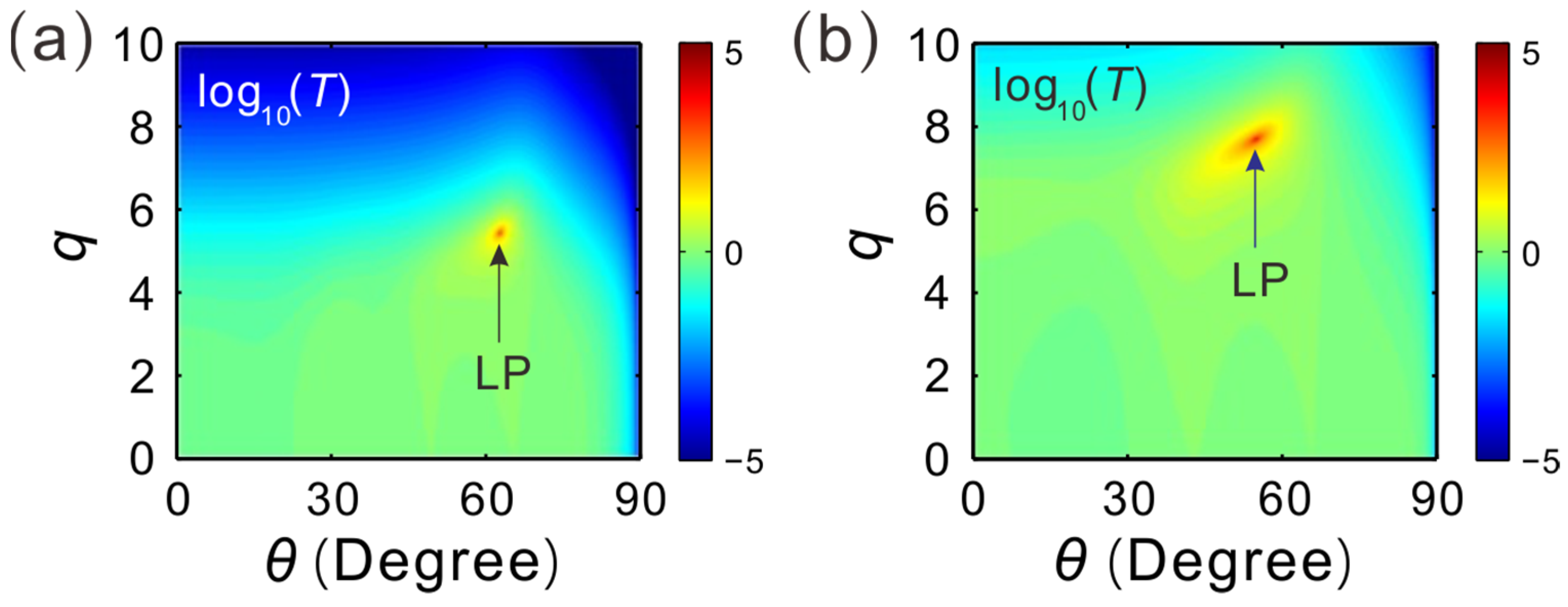
For different incident wavelengths,
Figure 6 gives the corresponding transmittance of light waves. There is one CPA−LP in
Figure 6a and another CPA−LP in
Figure 6b as well. The LP appears at [
θL = 62.85°,
qL = 5.4454] and the peak value of the transmittance is log
10(
T) = 2.8508 for
λ = 0.85 μm, whereas the other LP is situated at [
θL = 54.8°,
qL = 7.6977] and the maximum transmittance is log
10(
T) = 6.5361 for
λ = 1.55 μm. It demonstrates that the laser resonance may be realized by adjusting the loss/gain coefficient and the incident angle for different incident light wavelengths. At the laser point, the phase jump of π occurs in both the reflection coefficient phase and the transmission coefficient phase, thus realizing the half-wave shift in the phase of the transmitted light wave and the reflected light wave.
With a fixed incident wavelength, the PTX-symmetric dielectric structure supports a resonant laser point, that is, a CPA−LP. This point corresponds to the maximum transmittance and reflectance of light waves simultaneously. The reflection coefficient phase and the transmission coefficient phase have a phase jump of π at the laser point as well. This phase jump effect could be utilized to realize the half-wave phase shift in the transmission light wave and the reflection light wave. Furthermore, for different incident wavelengths, the positions of the CPA−LP in the parameter space are different, viz., the corresponding value of the incident angle and the loss/gain coefficient at the CPA−LP changes.


 ,
, 


