
Reconfiguration of Nematic Disclinations in Plane-Parallel Confinements


1
Department of Physics, Faculty of Mathematics and Physics, University of Ljubljana, 1000 Ljubljana, Slovenia
2
Department of Physics, Case Western Reserve University, Cleveland, OH 44106, USA
3
Department of Physics, Faculty of Natural Sciences and Mathematics, University of Maribor, 2000 Maribor, Slovenia
4
Solid State Department, Jožef Stefan Institute, 1000 Ljubljana, Slovenia
*
Author to whom correspondence should be addressed.
Crystals 2023, 13(6), 904; https://doi.org/10.3390/cryst13060904
Submission received: 20 April 2023
/
Revised: 23 May 2023
/
Accepted: 27 May 2023
/
Published: 1 June 2023
(This article belongs to the Special Issue Feature Articles in Liquid Crystals from Our Editorial Board Members and Their Colleagues, 2022/2023)
Abstract
:We study numerically the reconfiguration process of colliding strength disclinations in an achiral nematic liquid crystal (NLC). A Landau–de Gennes approach in terms of tensor nematic-order parameters is used. Initially, different pairs of parallel wedge disclination lines connecting opposite substrates confining the NLC in a plane-parallel cell of a thickness h are imposed: {1/2,1/2}, {−1/2,−1/2} and {−1/2,1/2}. The collisions are imposed by the relative rotation of the azimuthal angle of the substrates that strongly pin the defect end points. Pairs {1/2,1/2} and {−1/2,−1/2} “rewire” at the critical angle in all cases studied. On the other hand, two qualitatively different scenarios are observed for {−1/2,1/2}. In the thinner film regime , the disclinations rewire at . The rewiring process is mediated by an additional chargeless loop nucleated in the middle of the cell. In the regime , the colliding disclinations at reconfigure into boojum-like twist disclinations.
1. Introduction
Topological defects (TDs) appear at diverse natural scales [1], including in particle physics, condensed matter physics and cosmology. Their existence is enabled topologically, which is independent of systems’ microscopic details. In most cases, they exhibit localized singularities in the order parameter field that represent ordering in a symmetry-broken phase. Their essential properties are determined by topological charges that are topological invariants [2]. The related topological charge conservation rules determine their transformations, including merging and decaying processes.
TDs in uniaxial nematic liquid crystal [3] (NLC) phases and structures represent an ideal testbed to study diverse TDs. In particular, they exhibit a rich pallet of qualitatively different TD structures. Furthermore, TDs in NLCs could be relatively easily created, stabilized, manipulated and observed. The ordering within NLC configurations is commonly described by the nematic tensor order parameter Q. For the case of a uniaxial order, it is commonly expressed as in terms of the nematic uniaxial scalar-order parameter S and the nematic director field n, and stands for the unit tensor. The latter unit vector field points in the mesoscopic-scale local uniaxial LC direction and exhibits head-to-tail invariance (i.e., the states are physically equivalent). The amplitude S reflects the degree of nematic order. If distortions are present, then the NLC could locally enter biaxial states. Consequently, the cores of TDs, where the NLC order experiences relatively strong spatial variations, generally exhibit a biaxial order [4,5,6].
Of interest are line defects in NLCs. Their key properties are described by a 2D topological charge m and a 3D topological charge q [7]. The former quantity is also termed the “winding number” or Frank index [3], which is determined by the total reorientation of n when encircling a line defect center counter-clockwise. On the other hand, q reveals how many times n samples all possible 3D orientations on any surface enclosing the defect. In our work, we analyze reconfigurations of disclinations, which is the fundamental strength of a 2D defect. In bulk, they can form only closed loops. One must differentiate between wedge and twist disclinations, and the former are characterized by a constant sign of m. Close to the disclination core, the nematic director field exhibits spatial variations within the plane that are perpendicular to the disclination’s local orientation, which we henceforth refer to as the disclination plane. The associated 3D charge of wedge disclinations is expressed as . Therefore, closed-wedge loops are “charged” and appear to a distant observer to be point defects (i.e., the far director field of isolated TDs is distorted). On the other hand, the sign of m varies along the twist disclination, and the 3D charge of a closed twist loop equals zero [8,9,10] (i.e., they are “chargeless”). Consequently, an isolated twist disclination could be embedded within an essentially spatially homogeneous director structure. However, chargeless loops tend to decay into a topologically equivalent, defectless, locally homogeneous nematic structure. Furthermore, the nematic orientational order exhibits orientations out of the disclination plane along the twist disclination.
In confined geometries, disclinations could originate and terminate at bounding surfaces [3,11,12]. One can routinely enforce and stabilize a predetermined pattern of such disclinations in plane-parallel cells through appropriate treatment of confining surfaces [13,14,15,16,17,18,19,20]. One possible method is scribing a polymer alignment layer with the stylus of an atomic force microscope (AFM) [13].
2. Methods
We used a Landau—de Gennes mesoscopic model [21], where the nematic orientational order is described by the traceless symmetric tensor nematic-order parameter [22,23]
in terms of its eigenvectors and eigenvalues . It describes both the uniaxial and biaxial states, where the uniaxial states are commonly expressed as [21] . Here, is the scalar uniaxial-order parameter and is the nematic director field. In the positive uniaxial state, points along the eigenvector exhibiting the largest eigenvalue, which we align along Note that in the figures, where we show the orientational order, we plot the orientational field for .
The degree of biaxiality is measured by the biaxial parameter [22,23]
where and reflect the uniaxial and biaxial states, respectively. In particular, the condition corresponds to states exhibiting maximal biaxiality.
We express the free energy of the system as , where stands for the condensation- and elastic-free energy contributions, and the integral is carried over the whole NLC body. The latter is confined within the plane-parallel cell of a thickness h. At the bounding plates, we strongly enforce pairs of 2D defects. At the lateral sides of the NLC body, we implement free boundary conditions.
The free energy density terms are expressed as
Here, , and are material constants, is the supercooling temperature of the isotropic phase, and is the representative Landau-like nematic elastic constant in the single elastic constant approximation. In the simulations, we parametrize in the Cartesian coordinate frame as
where and are variational parameters. We introduce the dimensionless temperature [23] for scaling purposes, where is the superheating temperature and the scaled-order parameter is expressed as . Here, , and we scale distances with respect to the cell thickness . We express the resulting dimensionless free energy contributions as
3. Results
We studied reconfigurations of initially effectively parallel pairs {} of wedge disclinations within a plane-parallel confinement enforcing planar-type anchoring. Here, marks the i-th defect winding number, where we analyzed cases {1/2,1/2}, {−1/2,−1/2} and {−1/2,1/2}. The cell plates enforcing the surface point defects with planar nematic ordering were at z = 0 and z = h of the Cartesian system (x,y,z). The initial set-ups are shown in Figure 1a, Figure 2a, Figure 3a and Figure 4a. We assumed that the defect endpoints were strongly pinned to the confining surfaces. The defect reconfigurations were enforced by the relative azimuthal rotation with an angle for the facing confining plates. Initially, the defect ends were pinned at points () = (±R/2,0) at each plate. We represented the disclination lines by plotting the regions where the defect-induced biaxiality was relatively strong. Upon increasing —in the simulations, we rotated the lower plate—the length of the disclinations increased, which was energetically costly. Specifically, the free energy penalty of a straight disclination was, in general, linearly proportional to its length. At a critical rotation angle, the disclinations exhibited reconfigurations that prevented further elongation of the disclinations. The resulting process exhibited either a periodic structural transformation within or a transformation into the qualitatively different boojum-like pattern.
3.1. Pairs {1/2,1/2} and {−1/2,−1/2}
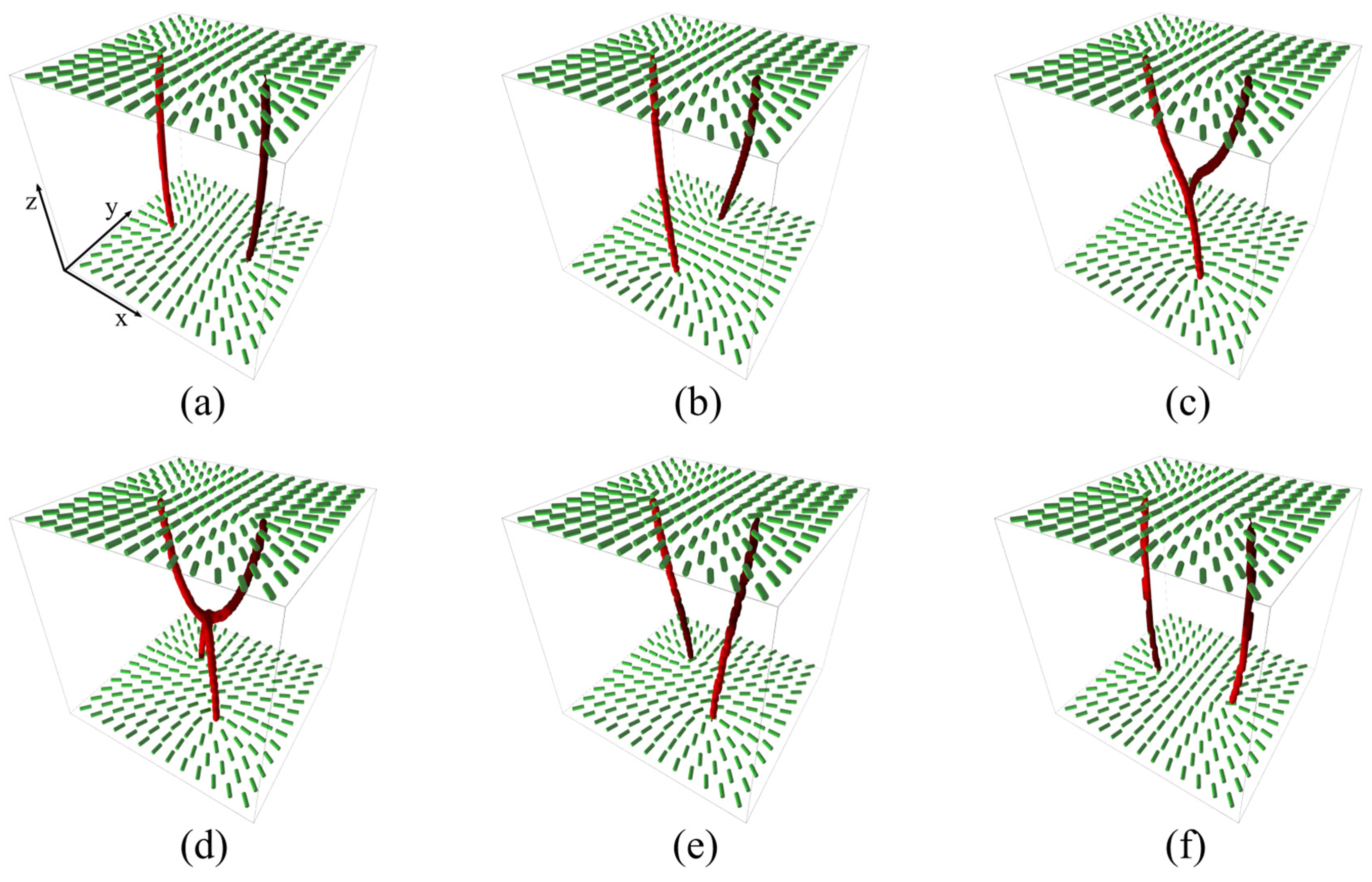
We first considered a pair of {1/2,1/2} disclinations that were initially approximately parallel (i.e., (Figure 1a)). Note that the disclinations mutually repelled and were therefore slightly bent outward with respect to each other. In planar 2D systems, their mutual repulsive interaction per disclination unit length is approximately [3], where is the distance between the centers of defects, the nematic order parameter correlation length measures the characteristic size of defects’ cores and K stands for the representative Frank elastic constant. The far director field in any (x,y) plane is essentially radial from the central line located at (x,y) = (0,0). Upon increasing , the lengths of the disclinations progressively increased until the critical angle was reached. The representative patterns for are shown in Figure 1b,c. At the critical angle, the cores of the defects joined, forming a single m = 1 two-dimensional defect in the (x,y) plane at z = h/2 (see Figure 1d). Figure 5 shows representative nematic cross-sections in the (x,y) plane. All the cross-sections possess a separated pair of m = ½ singularities. Figure 5c shows the case close to the merging point, where the two disclinations tended to merge via an intermediate m = 1 profile at z = h/2. This allowed the exchange of defect segments of disclinations, which enabled a decrease in disclination lengths upon further increasing . Therefore, the upper (extending above z = h/2) part of the first disclination joined the bottom (extending below z = h/2) part of the second disclination, which emerged as a new first single line at . A representative structure is shown in Figure 1e. Simultaneously, the bottom part of the first disclination joined the upper part of the second disclination, which joined into a new second disclination. The whole reconfiguration is shown in more detail in Video S1 (see Supplementary Materials). This structural reconfiguration exhibited periodic behavior in θ with respect to a unit period. In Figure 6a, we plot the total length hd of both disclinations upon increasing
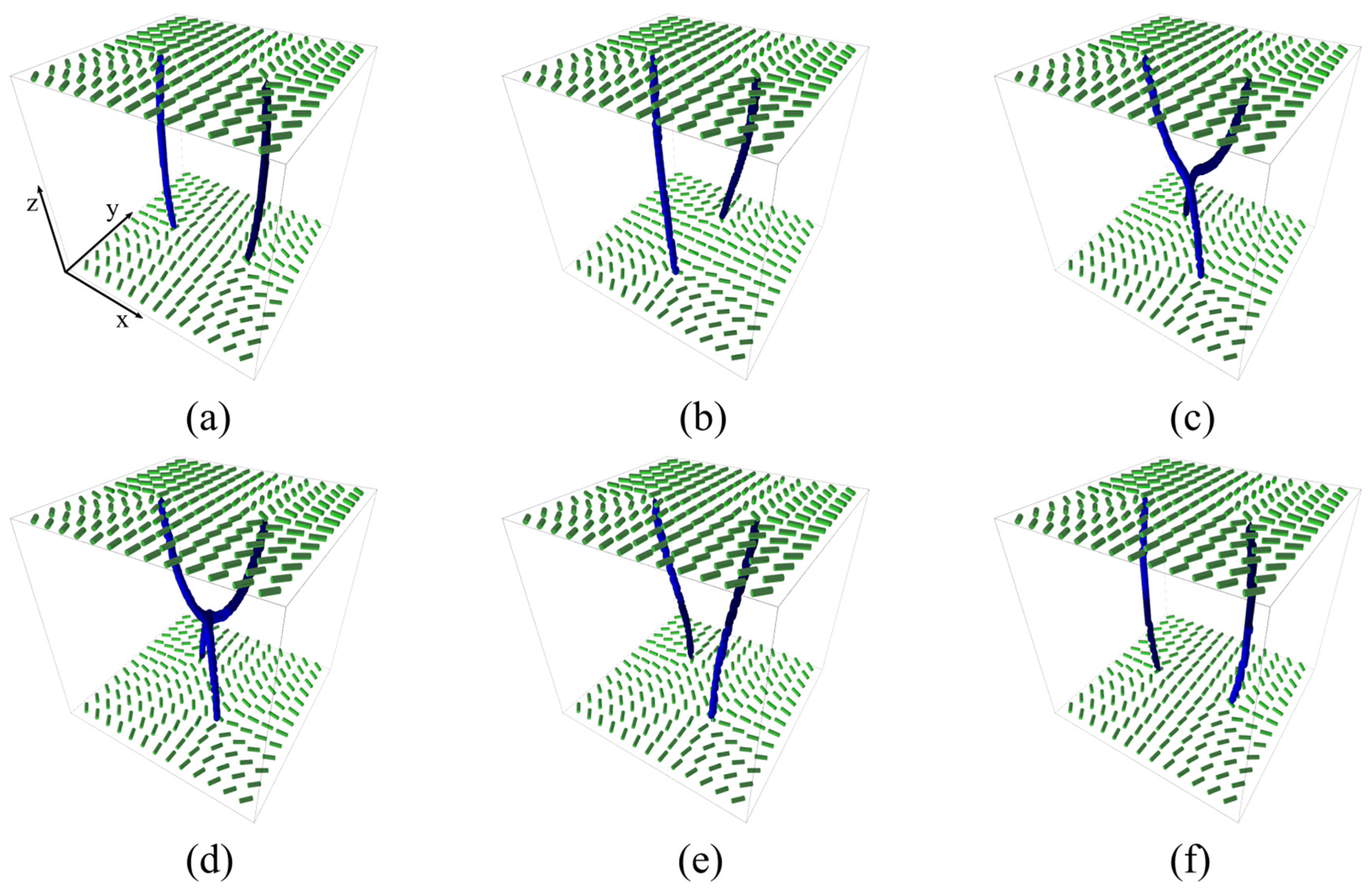
In Figure 2 (and Supplementary Video S2), we show the rotation-induced reconfiguration of the {−1/2,−1/2} disclinations, where intermediate configurations for the same vales of are shown as in Figure 1. In the approximation of equal elastic constants, the reconfiguration process was qualitatively and even quantitatively (with respect to disclination axis direction variations) the same for the {−1/2,−1/2} and {1/2,1/2} pairs. In Figure 6b, we plot the total length hd of both disclinations upon increasing .
Note that we observed qualitatively the same structural behavior for all studied cell thicknesses (we probed the behavior in cells up to the maximal thickness h = 2R). One would intuitively expect that in thick enough cells, two boojums would be formed at the confining plates while a nonsingular escaped radial–like nematic structure would be formed in between. In this structure, the nematic director field “escapes” along the z-direction in the region mediating the facing boojums and in such a way that the LC configuration avoids the singularity in nematic ordering. However, our simulations suggest that the energy barrier separating the structures that we presented and the topologically equivalent escaped-like configurations were, in our studied cases, too large to be triggered by a disclination collision. For instance, a similar competition of topologically equivalent structures was realized in a nematic LC confined to a cylindrical confinement [25] where the lateral walls impose homeotropic anchoring (i.e., the nematic director field tends to be aligned along the surface normal of a confining surface patch). In these cases, the competing structures were (i) the escaped radial structure, (ii) the escaped radial structure with point defects (ERPD), (iii) the radial structure exhibiting non-escaped m = 1 disclination along the cylinder symmetry axis and (iv) the planar radial structure possessing two parallel m = 1/2 disclinations along the cylinder axis. These structures are topologically equivalent, and there exist continuous nematic-order parameter field transformations among the competing configurations. Here, cases (ii) and (iv) are the corresponding analogues of a structure consisting of two boojums and of a configuration exhibiting an {m,m} pair of disclinations, respectively. Specifically, ERPD structures consist of a sequence of alternating hedgehog and anti-hedgehog point defects along the cylinder axis. An LC volume segment between a neighboring hedgehog-anti-hedgehog pair, where we take into account only half of each point defect (which could, in general, form a ring-like structure [5]), is a topological analogue of a structure consisting of two boojums in our geometrical setting.
3.2. Pairs {−1/2,1/2}
We next consider the reconfigurational transformations imposed by increasing the angle of the initially effectively parallel disclination pairs {−1/2,1/2}. Qualitatively different behavior was observed for h > and h < , where stands for the critical thickness.
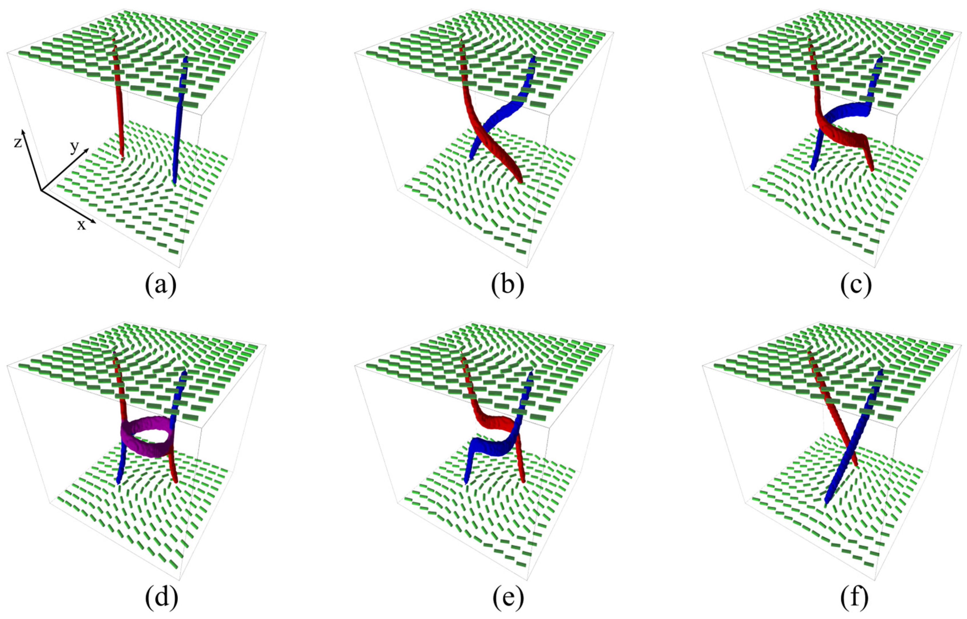
We first considered the case h < For , the disclinations were slightly bent inward because the facing segments in each (x,y) plane experienced attraction (see Figure 3a). The nematic director far field at distances large with respect to was essentially spatially homogeneous because the total winding number within each (x,y) plane equaled zero. Representative structures upon increasing are depicted in Figure 3b–f and in Supplementary Videos S3 and S4. One can see that for , there existed two wedge disclinations. Note that the director field surrounding each wedge disclination tended to be confined within the plane perpendicular to the disclinations’ orientations. Upon approaching , the interaction between defects increased, and a kink-like structure was formed (Figure 3c) in nearby disclination segments. At , the local conditions in this region were established to form a charge loop in the (x,y) plane centered at z = h/2 (Figure 3d). In this plane, the loop mediated the {m = 1/2, m = −1/2} segments, which effectively enabled the existence of two approximately straight chargeless disclinations running along the z coordinate. Therefore, the nematic pattern at consisted of three chargeless loops. The representative (x,y) cross-sections are depicted in Figure 7. The additional chargeless loop hosted in the (x,y) plane at z = h/2 enabled the immersion of the central domain (globally oriented along the y axis) into the surrounding pattern, where the nematic far field was essentially homogeneously aligned along the x direction. This intermediate structure possessed a circular ring within the (x,y) plane at z = h/2, whose biaxial structure exhibited a markedly different appearance in comparison with the other line defect structures that we observed in this study. In particular, in the regime where , the structure consisted of edge disclinations in which the nematic structure within the disclination plane was essentially planar (i.e., two of the Q eigenvectors lied within the disclination plane). On the contrary, the ring formed at consisted of a twist dislocation ring along which the Q eigenvector frame also explored orientations that did not coincide with the disclination plane. In addition, the nematic structure within the (x,y) plane hosting the ring was, on average, confined in this plane, where the domain-like orientational ordering within and outside the ring were approximately perpendicular to each other. This constrained local distortion gave rise to the relatively broad band appearance of the ring’s biaxial profile. Just above , two wedge disclinations emerged again (Figure 3e,f). Note that the collision of two disclination segments exhibiting different winding number signs requires an intermediate region where the nematic order is pushed out of the disclination planes. The total disclination length upon increasing is depicted in Figure 6c.
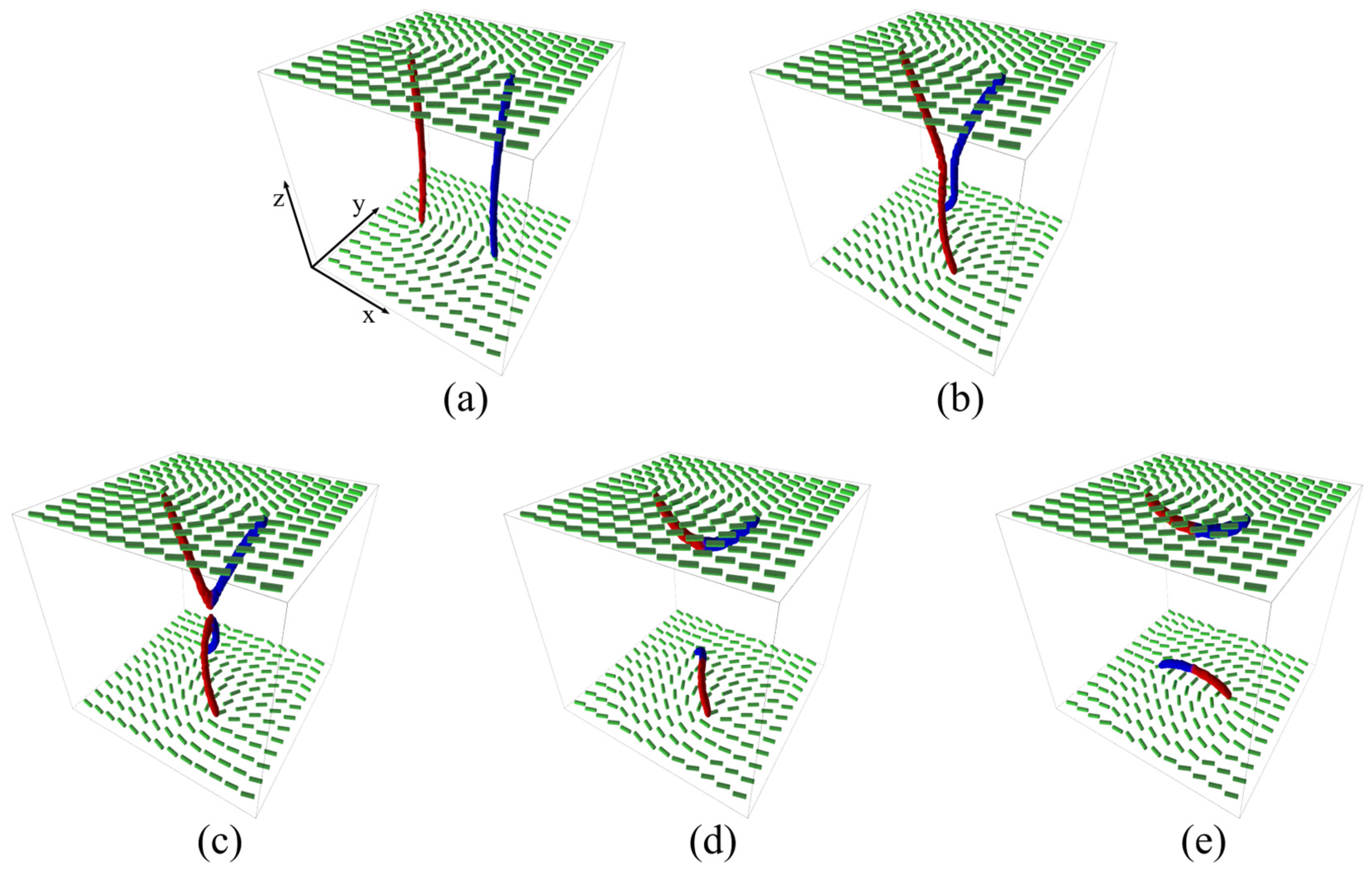
Next, we analyzed the case where h > which is shown in Figure 4 (and Supplementary Videos S5 and S6). In this case, the energy barrier between the structure consisting of two disclinations spanning the opposite plates and the structure resembling boojum-like dislocations (see Figure 4c,e) confined to the bounding plates was small enough so that upon increasing , the latter structure was established. Note that this transition was discontinuous. The nematic structure in the selected (x,y) planes is shown in Figure 8. In this scenario, the central region of the cell was essentially homogenously aligned along the x axis.
4. Conclusions
We numerically studied the structural reconfigurations of nematic disclinations in plane-parallel cells. Transformations were enforced by relative rotation of the confining plates, which strongly pinned the end points of the disclinations. The initial (non-rotated) configurations exhibited essentially parallel wedge disclinations spanning the facing plates. Upon increasing the azimuthal rotation angle the total disclination length in the beginning increased, which was energetically expensive. Specifically, the energy cost of an isolated straight disclination linearly increased with its length. However, when the critical value of was reached, the disclinations locally merged, which enabled their reconnection or reconfiguration. As a consequence, the resulting total disclination length did not monotonically increase upon increasing .
We first discussed the transformation of pairs of disclinations possessing the same winding number. Note that such neighboring disclination segments mutually repel. Therefore, a local collision in which the repelling segments merge reflects a local energy “sacrifice”, which opens a transformation channel toward a configuration possessing a lower total free energy cost. In this transformation, the character of the disclinations does not change (i.e., the system exhibits two wedge disclinations before and after the collision).
The rotationally induced reconfiguration of initially parallel {−1/2,1/2} disclinations exhibited more complex behavior. In this case, the facing segments experienced mutual attraction. Therefore, in the initial configuration, the disclinations must be separated well enough (i.e., the distance R in our notation) to avoid contact in the middle of the cell. The latter would open the door to the formation of two chargeless loops. These display a boojum-like configuration with localized nematic distortions, where the remaining part of the cell would exhibit an essentially spatially homogeneous structure. Such a condition is achieved if the cell thickness is above the critical value .
We remark that line-like topologically protected structures [26,27,28] are ubiquitous in nature and exhibit several universal features, owing to their topological origin. They exhibit robust body-like structures, and their stability is guaranteed by relevant topological invariants [26,27]. (In our case, these were 2D and 3D topological charges.) Of particular interest are topologically protected knotted configurations in particle physics [28], as they might provide a pathway to stabilizing stable localized field states representing “particles”, assuming the physical fields represent fundamental natural entities [29]. Controlling the formation of knots in physical fields [30,31,32,33,34,35] might also have numerous practical applications, as knots are difficult to untie. Our study revealed that the line defects examined in the presented geometrical set-up did not form knots. However, they could form knotted structures in the presence of colloids [35].
Supplementary Materials
The following supporting information can be downloaded at https://www.mdpi.com/article/10.3390/cryst13060904/s1. Video S1: Structural reconfiguration of a pair {1/2,1/2} disclinations on increasing The video is slowed down in the moment of contact to better show the exchange. . Note that the scaling along vertical and horizontal directions are different. Line defects are indicated by colored regions where . Video S2: Structural reconfiguration of a pair {−1/2,−1/2} disclinations on increasing The video is slowed down in the moment of contact to better show the exchange. . Video S3: Structural reconfiguration of a disclination pair {1/2,−1/2} on increasing Video S4: A slowed down video of the structural reconfiguration shown in Video S3 with the slowed down focus on the exchange. Video S5: Structural reconfiguration of a disclination pair {1/2,−1/2} on increasing Video S6: A slowed down video of the structural reconfiguration shown in Video S5 with the slowed down focus on the exchange. .
Author Contributions
Conceptualization, S.K. and C.R.; methodology, S.H.; validation, S.H., S.K. and C.R.; formal analysis, S.H.; investigation, S.H.; data curation, S.H.; writing—original draft preparation, S.H., S.K. and C.R.; writing—review and editing, S.H., S.K. and C.R.; visualization, S.H. All authors have read and agreed to the published version of the manuscript.
Funding
This research was funded by the Slovenian research agency (ARRS), grant number P1-0099, and by the National Science Foundation’s Division of Materials Research, grant number DMR1901797.
Institutional Review Board Statement
Not applicable.
Informed Consent Statement
Not applicable.
Data Availability Statement
Data generated and supporting the findings of this article are available from the corresponding author upon reasonable request.
Acknowledgments
The authors acknowledge fruitful discussions with Adam Susser.
Conflicts of Interest
The authors declare no conflict of interest.
References
- Zurek, W.H. Cosmological experiments in superfluid helium? Nature 1985, 317, 505–508. [Google Scholar] [CrossRef]
- Kleman, D.; Michel, L.; Toulouse, G. Classification of topologically stable defects in ordered media. J. Phys. Lett. 1977, 38, 195–197. [Google Scholar] [CrossRef]
- Kleman, M.; Lavrentovich, O.D. Soft Matter Physics: An Introduction; Springer Science & Business Media: New York, NY, USA, 2007. [Google Scholar] [CrossRef]
- Schopohl, N.; Sluckin, T.J. Defect Core Structure in Nematic Liquid Crystals. Phys. Rev. Lett. 1987, 59, 2582–2584. [Google Scholar] [CrossRef] [PubMed]
- Kralj, S.; Virga, E.G.; Žumer, S. Biaxial torus around nematic point defects. Phys. Rev. E 1999, 60, 1858. [Google Scholar] [CrossRef]
- Zhou, S.; Shiyanovskii, S.V.; Park, H.S.; Lavrentovich, O.D. Fine Structure of the Topological Defect Cores Studied for Disclinations in Lyotropic Chromonic Liquid Crystals. Nat. Commun. 2017, 8, 14974. [Google Scholar] [CrossRef]
- Lavrentovich, O.D. Topological defects in dispersed liquid crystals, or words and worlds around liquid crystal drops. Liq. Cryst. 1998, 24, 117–126. [Google Scholar] [CrossRef]
- Ferris, A.J.; Afghah, S.; Selinger, R.L.B.; Selinger, J.V.; Rosenblatt, C. Electric field-induced crossover from 3D to 2D topological defects in a nematic liquid crystal: Experimental verification. Soft Matter. 2020, 16, 642–650. [Google Scholar] [CrossRef]
- Nikkhou, M.; Škarabot, M.; Čopar, S.; Ravnik, M.; Žumer, S.; Muševič, I. Light-controlled topological charge in a nematic liquid crystal. Nat. Phys. 2015, 11, 183. [Google Scholar] [CrossRef]
- Harkai, S.; Murray, B.S.; Rosenblatt, C.; Kralj, S. Electric field driven reconfigurable multistable topological defect patterns. Phys. Rev. Res. 2020, 2, 013176. [Google Scholar] [CrossRef]
- Chuang, I.; Durrer, R.; Turok, N.; Yurke, B. Cosmology in the Laboratory: Defect Dynamics in Liquid Crystals. Science 1991, 251, 1336. [Google Scholar] [CrossRef]
- Backer, A.S.; Callan-Jones, A.C.; Pelcovits, R.A. Nematic cells with defect-patterned alignment layers. Phys. Rev. E 2008, 77, 021701. [Google Scholar] [CrossRef] [PubMed]
- Murray, B.S.; Pelcovits, R.A.; Rosenblatt, C. Creating arbitrary arrays of two-dimensional topological defects. Phys. Rev. E 2014, 90, 052501. [Google Scholar] [CrossRef]
- Culbreath, C.; Glazar, N.; Yokoyama, H. Note: Automated maskless micro-multidomain photoalignment. Rev. Sci. Instr. 2011, 82, 126107. [Google Scholar] [CrossRef] [PubMed]
- Glazar, N.; Culbreath, C.; Li, Y.; Yokoyama, H. Switchable liquid-crystal phase-shift mask for super-resolution photolithography based on Pancharatnam–Berry phase. Appl. Phys. Expr. 2015, 8, 116501. [Google Scholar] [CrossRef]
- Wang, M.; Li, Y.; Yokoyama, H. Artificial web of disclination lines in nematic liquid crystals. Nat. Comm. 2017, 8, 388. [Google Scholar] [CrossRef]
- Gao, Y.; Jiang, M.; Chehui, P.; Sun, K.; Yaroshchuk, O.; Lavrentovich, O.D.; Wei, Q.-H. High-Resolution and High-Throughput Plasmonic Photopatterning of Complex Molecular Orientations in Liquid Crystal. Adv. Mater. 2016, 28, 2353–2358. [Google Scholar] [CrossRef]
- Yu, H.; Jiang, M.; Guo, Y.; Turiv, T.; Lu, W.; Ray, V.; Lavrentovich, O.D.; Wei, Q.-H. Plasmonic Metasurfaces with High UV–Vis Transmittance for Photopatterning of Designer Molecular Orientations. Adv. Opt. Mater. 2019, 7, 1900117. [Google Scholar] [CrossRef]
- Guo, Y.; Jiang, M.; Afghah, S.; Peng, C.; Selinger, R.L.B.; Lavrentovich, O.D.; Wei, Q.-H. Photopatterned Designer Disclination Networks in Nematic Liquid Crystals. Adv. Opt. Mater. 2021, 9, 2100181. [Google Scholar] [CrossRef]
- Peng, C.; Guo, Y.; Turiv, T.; Jiang, M.; Wei, Q.-H.; Lavrentovich, O.D. Patterning of Lyotropic Chromonic Liquid Crystals by Photoalignment with Photonic Metamasks. Adv. Mater. 2017, 29, 1606112. [Google Scholar] [CrossRef]
- De Gennes, P.G.; Prost, J. The Physics of Liquid Crystals; Clarendon Press: Oxford, UK, 1994. [Google Scholar]
- Kralj, S.; Virga, E.G. Universal Fine Structure of Nematic Hedgehogs. J. Phys. A Math. Gen. 2001, 34, 829. [Google Scholar] [CrossRef]
- Bisi, F.; Gartland, E.C.; Rosso, R.; Virga, E.G. Order reconstruction in frustrated nematic twist cells. Phys. Rev. E 2003, 68, 021707. [Google Scholar] [CrossRef]
- Hamdi, R.; Lombardo, G.; de Santo, M.P.; Barberi, R. Biaxial coherence length in a nematic π-cell. Eur. Phys. J. E 2013, 36, 115. [Google Scholar] [CrossRef] [PubMed]
- Kralj, S.; Žumer, S. The saddle-splay surface elasticity of nematic structures confined to a cylindrical capillary. Phys. Rev. E 1995, 51, 366–379. [Google Scholar] [CrossRef]
- Kurik, M.V.; Lavrentovich, O.D. Defects in Liquid Crystals: Homotopy Theory and Experimental Studies. Sov. Phys. Usp. 1988, 31, 196. [Google Scholar] [CrossRef]
- Singer, I.M. Differential geometry, fiber bundles and physical theories. Physics Today 1982, 35, 41. [Google Scholar] [CrossRef]
- Skyrme, T.H.R. A unified field theory of mesons and baryons. Nucl. Phys. 1962, 31, 556. [Google Scholar] [CrossRef]
- Hobson, A. There are no particles, there are only fields. Am. J. Phys. 2013, 81, 211. [Google Scholar] [CrossRef]
- Rößler, U.K.; Bogdanov, A.N.; Pfleiderer, C. Spontaneous skyrmion ground states in magnetic metals. Nature 2006, 442, 797. [Google Scholar] [CrossRef]
- Fukuda, J.; Žumer, S. Quasi-two-dimensional Skyrmion lattices in a chiral nematic liquid crystal. Nat. Commun. 2011, 2, 246. [Google Scholar] [CrossRef]
- Smalyukh, I.I. Review: Knots and other new topological effects in liquid crystals and colloids. Rep. Prog. Phys. 2020, 83, 106601. [Google Scholar] [CrossRef]
- Sutcliffe, P. Skyrmion Knots in Frustrated Magnets. Phys. Rev. Lett. 2017, 118, 247203. [Google Scholar] [CrossRef] [PubMed]
- Shen, Y.; Yu, B.; Wu, H.; Li, C.; Zhu, Z.; Zayats, A.V. Topological transformation and free-space transport of photonic hopfions. Adv. Photon. 2023, 5, 015001. [Google Scholar] [CrossRef]
- Muševič, I.; Škarabot, M.; Tkalec, U.; Ravnik, M.; Žumer, S. Two-dimensional nematic colloidal crystals self-assembled by topological defects. Science 2006, 313, 5789. [Google Scholar] [CrossRef] [PubMed]
Figure 1.
Structural reconfiguration of a pair {1/2,1/2} of disclinations upon increasing . (a) Initial structure at . The two line defects have different shades of red to assist the reader in recognizing the reconfiguration. (b) A representative rotated pattern, where . At , the disclinations exchange their segments, where (c) is just before contact, (d) is at the moment of contact and (e) is after the exchange. (f) Pattern after full rotation, which is equal to (a) . Note that the scaling along the vertical and horizontal directions is different. Line defects are indicated by colored regions, where .

Figure 2.
Structural reconfiguration of a pair {−1/2,−1/2} of disclinations upon increasing . (a) Initial structure at . The two line defects have different shades of blue to assist the reader in recognizing the reconfiguration. (b) A representative rotated pattern, where . At , the disclinations exchange their segments, where (c) is just before contact, (d) is at the moment of contact, and (e) is just after the exchange. (f) Pattern after full rotation, which is equal to (a) . For presentation purposes, the scaling along vertical and horizontal directions is different. Line defects are indicated by colored regions, where .

Figure 3.
Structural reconfiguration of a disclination pair {1/2,−1/2} upon increasing . (a) Initial structure at . (b,c) Representative rotated patterns, where . (d) The structure at consists of two nearly straight and one loop-like chargeless disclination (purple). (e,f) Representative rotated patterns in the regime . . For presentation purposes, the scaling along the vertical and horizontal directions is different. Line defects are indicated by colored regions, where .

Figure 4.
Structural reconfiguration of disclinations upon increasing , where the initial structure consists of defects bearing different winding numbers and where . (a) Initial structure at . (b) . (c) Configuration at . (d) Configuration slightly above , (e) . . For presentation purposes, the scaling along the vertical and horizontal directions is different. Line defects are indicated by colored regions, where .

Figure 5.
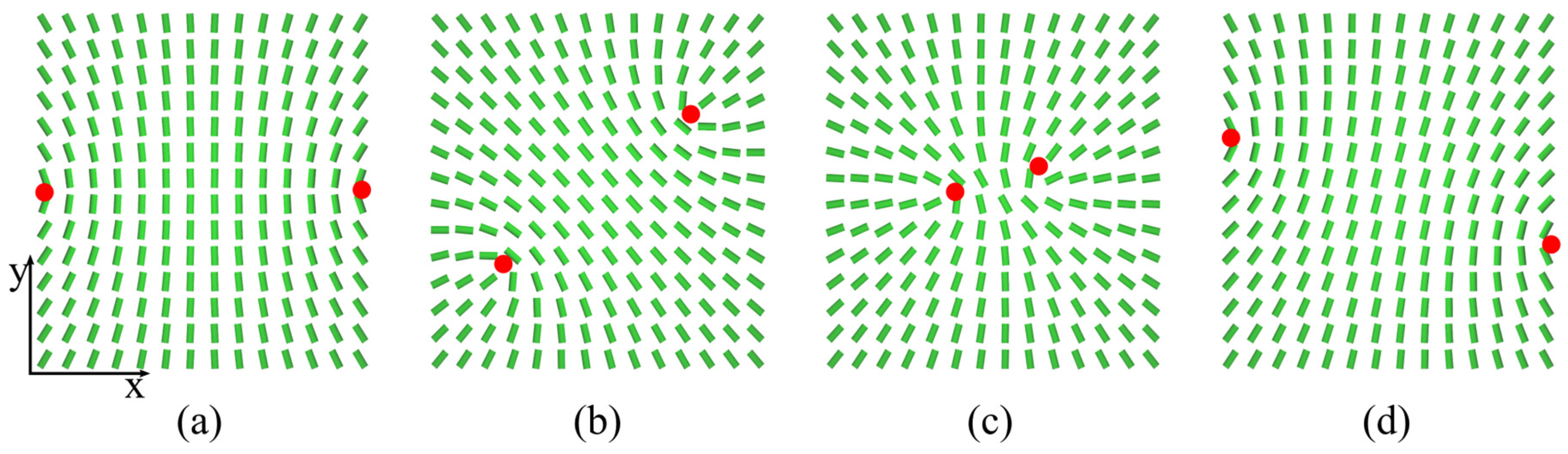
Representative nematic structures in (x,y) cross-sections in the middle of the cell at different values of for the pair of {1/2,1/2} disclinations: (a) , (b) , (c) and (d) . Red dots mark defect centers.
Figure 5.
Representative nematic structures in (x,y) cross-sections in the middle of the cell at different values of for the pair of {1/2,1/2} disclinations: (a) , (b) , (c) and (d) . Red dots mark defect centers.

Figure 6.
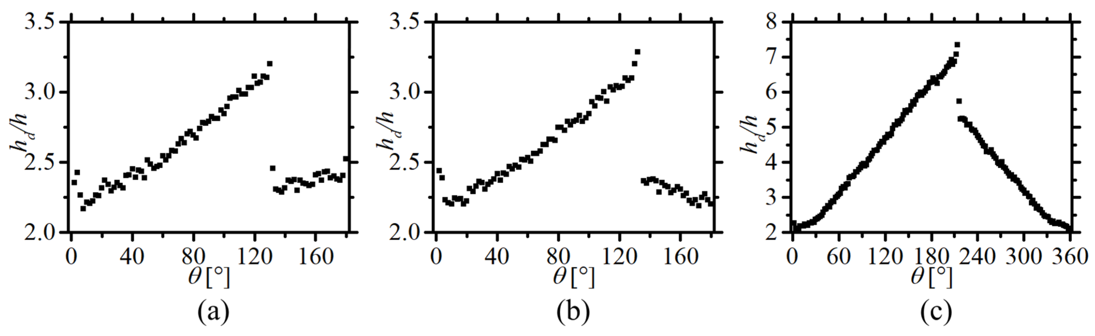
The total disclination length hd variation upon increasing . (a) {1/2,1/2}. (b) {−1/2,−1/2}, . (c) {1/2,−1/2}, .
Figure 6.
The total disclination length hd variation upon increasing . (a) {1/2,1/2}. (b) {−1/2,−1/2}, . (c) {1/2,−1/2}, .

Figure 7.
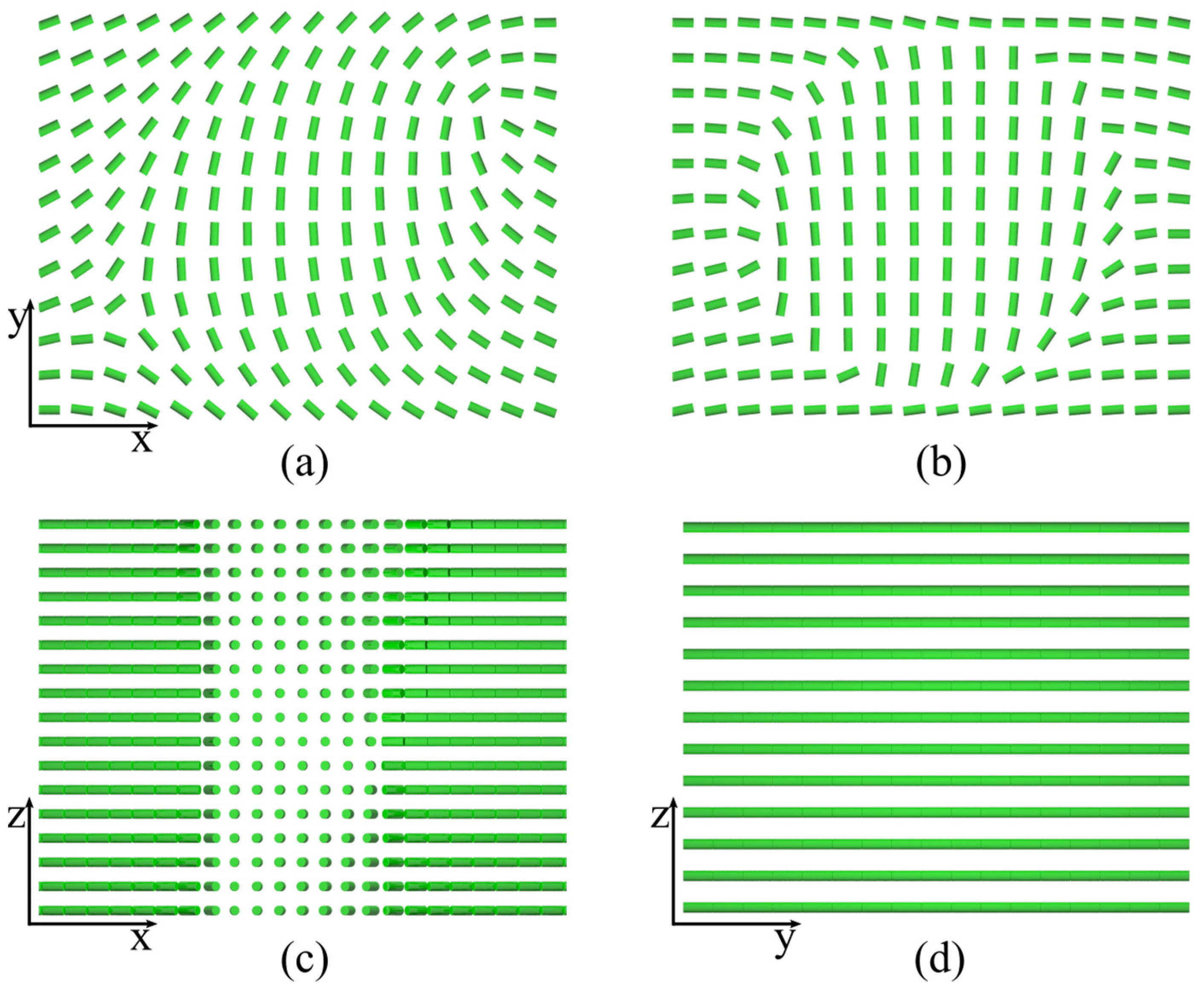
Representative nematic structures at in (x,y) cross-sections at (a) , (b) in (x,z) cross-sections, where h < , (c) (x,z) and (d) (y,z) cross-sections through the middle of the cell (with respect to (c) x or (d) y).
Figure 7.
Representative nematic structures at in (x,y) cross-sections at (a) , (b) in (x,z) cross-sections, where h < , (c) (x,z) and (d) (y,z) cross-sections through the middle of the cell (with respect to (c) x or (d) y).

Figure 8.
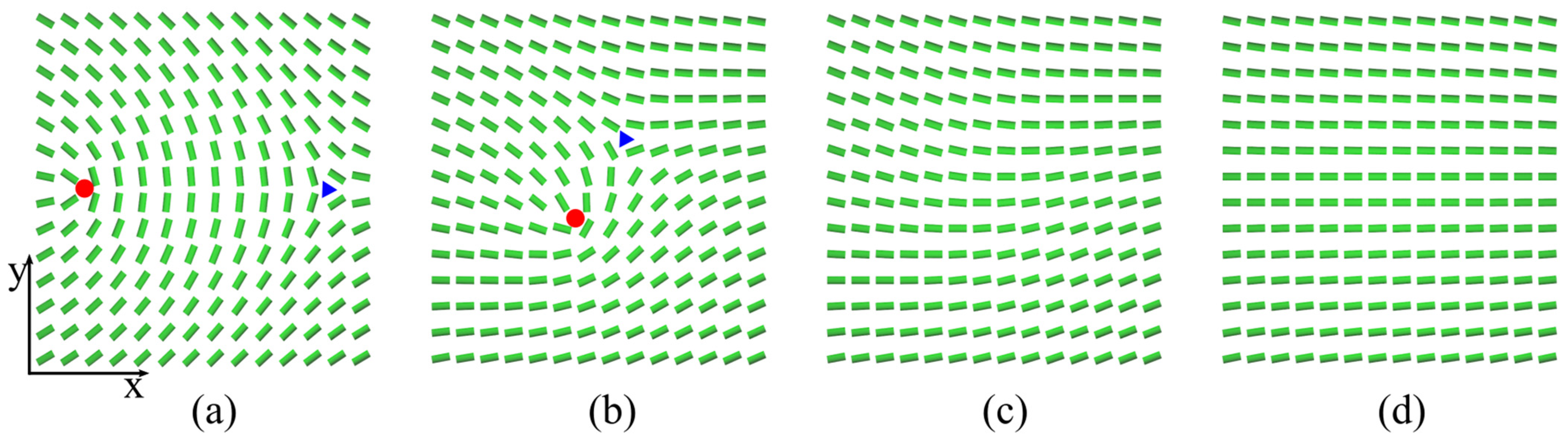
Representative nematic structures in (x,y) cross-sections at z = h/2 different values of for h>: (a) , (b) , (c) and (d) . Red dot (blue triangle) marks m = 1/2 (m = −1/2) defect center.
Figure 8.
Representative nematic structures in (x,y) cross-sections at z = h/2 different values of for h>: (a) , (b) , (c) and (d) . Red dot (blue triangle) marks m = 1/2 (m = −1/2) defect center.

Disclaimer/Publisher’s Note: The statements, opinions and data contained in all publications are solely those of the individual author(s) and contributor(s) and not of MDPI and/or the editor(s). MDPI and/or the editor(s) disclaim responsibility for any injury to people or property resulting from any ideas, methods, instructions or products referred to in the content. |
© 2023 by the authors. Licensee MDPI, Basel, Switzerland. This article is an open access article distributed under the terms and conditions of the Creative Commons Attribution (CC BY) license (https://creativecommons.org/licenses/by/4.0/).
Share and Cite
MDPI and ACS Style
Harkai, S.; Rosenblatt, C.; Kralj, S. Reconfiguration of Nematic Disclinations in Plane-Parallel Confinements. Crystals 2023, 13, 904. https://doi.org/10.3390/cryst13060904
AMA Style
Harkai S, Rosenblatt C, Kralj S. Reconfiguration of Nematic Disclinations in Plane-Parallel Confinements. Crystals. 2023; 13(6):904. https://doi.org/10.3390/cryst13060904
Chicago/Turabian StyleHarkai, Saša, Charles Rosenblatt, and Samo Kralj. 2023. "Reconfiguration of Nematic Disclinations in Plane-Parallel Confinements" Crystals 13, no. 6: 904. https://doi.org/10.3390/cryst13060904
Note that from the first issue of 2016, this journal uses article numbers instead of page numbers. See further details here.