
Evaluation of Strength and Microstructural Properties of Heat Treated High-Molybdenum Content Maraging Steel


1
CEREM, Deanship of Scientific Research, King Saud University, P.O. Box 800, Riyadh 11421, Saudi Arabia
2
Steel Technology Department, Central Metallurgical R&D Institute (CMRDI), P.O. Box 87, Helwan 11731, Egypt
3
Department of Physics, College of Science, Shaqra University, Shaqra 15556, Saudi Arabia
4
Department of Mechanical Engineering, College of Engineering, King Saud University, P.O. Box 800, Riyadh 11421, Saudi Arabia
*
Author to whom correspondence should be addressed.
Crystals 2021, 11(12), 1446; https://doi.org/10.3390/cryst11121446
Submission received: 10 October 2021
/
Revised: 14 November 2021
/
Accepted: 19 November 2021
/
Published: 24 November 2021
(This article belongs to the Special Issue New Trends in Crystals at Saudi Arabia)
Abstract
:Effect of high molybdenum content ~10% as an alloying element on the strength and microstructural properties of 11% nickel—1.25% titanium maraging steel was evaluated. To increase the homogeneity and cleanliness of produced ingot, the investigated steel sample was produced by melting the raw material in an open-air induction melting furnace followed by refining utilizing a direct current electro-slag refining machine. The produced steel samples were both forged and heat-treated in optimum condition to acquire the full capacity of mechanical properties especially the tensile properties. After Forging and heat treatment at optimum condition, steel samples were evaluated by optical microscopy (OM), X-ray diffraction (XRD), differential scanning calorimetry (DSC) analysis, electron backscattering diffraction (EBSD), and transmission electron microscopy (TEM). The experimental data showed that this steel sample has ultimate strength ~2100 MPa and elongation around 14%. High tensile properties obtained may be attributed on one hand due to the presence of high alloying lamellar martensite phase and lamellar austenite phase which has high dislocation intensity, and on the other hand, due to the high homogeneity and cleanliness of investigated samples from large nonmetallic inclusions. The results also show that a high amount of intermetallic compounds (NiMo3 and NiTi3) which are completely round and have a very low size not more than hundred nanometers.
1. Introduction
Maraging steel owed this name due to its structure and applied heat treatment process martensite induced aging, which mean aged martensite. Maraging steels usually consist of a relatively soft and ductile martensitic matrix of very low carbon content strengthened by the precipitation of a large number of nanometer sized intermetallic compound phases [1,2,3]. As a result, this type of steels exhibits an excellent combination of ultrahigh strength with good fracture toughness, and therefore is widely used for critical applications in the aerospace application sector since first developed some 40 years ago [4]. Traditional maraging steels such as the 18Ni grades (200, 250, 300, 350 and etc.) where the number signifies the yield strength in ksi) contain around 18 wt% Ni with high levels of Co (8~13 wt%) and Mo (3~5 wt%) as well as smaller additions of other alloying elements such as Ti and Al [5]. Low carbon and alloyed maraging steels are capable of increasing their mechanical resistance and hardness after aging heat treatments. The solution treated state has a martensitic structure with high ductility and toughness, and it can be modified after aging heat treatments [6].
It is reported that in the 18-Ni 300 alloy and in similar grades, the Ni3Ti phase (or more generally, Ni3X where X = Ti, Mo, V, and W) readily form on short-term aging at low temperatures (400–450 °C), followed by Fe2Mo or Fe7Mo6 precipitation [7,8,9,10,11]. Aging at temperatures exceeding 500 °C concurrently promotes the formation of austenite by a diffusion-controlled reaction, which is also favoured by the release of Ni into the matrix due to decomposition of Ni3Ti phase [3,7,9,10,11,12,13,14]. The alloying elements of maraging steel, such as molybdenum, titanium, nickel, cobalt, aluminium, and others, have a great influence on the mechanical properties of this alloy, in other words, they are responsible as precipitates hardeners [6].
The strengthening efficacy of maraging steel is mainly controlled through solution treatment (ST) followed by ageing treatment (AT) [15]. With ST, alloying elements can enter into the substrate lattice and increase the lattice distortion, thereby increasing the hardenability and promoting the martensite transformation. With AT, the internal stress caused by quenching could be released and evenly distributed nano-precipitates would form in the substrate, enhancing both strength and toughness. Additionally, plastic deformation is often used before ST and AT to increase the density of dislocations, refine the microstructure, and more importantly, provide extra energy for precipitation and martensitic transformation during the ST and AT [16]. Generally, the strengthening strategy is associated with the precipitate phase formed during AT. The common precipitates are usually Mo-enriched, Ti-enriched, Al-enriched phases, and carbides, such as Ni3(Ti, Mo) [17], Ni3Mo [18], Fe7Mo6 [18], Ni3Ti [19], Fe2Mo [19], Ni3Al [19], NiAl [20], and NbC [21]. The introduction of reversed γ has become one of the most effective method to improve the strength-toughness properties. The segregation of γ-stabilizing elements, such as Ni and Mn, can often promote the austenite reversion at the martensite boundaries during aging treatment. Meanwhile, the effect of nano-precipitation on the austenite reversion should be considered. It was demonstrated that the dissolving of Ni3Ti in the overaged state facilitated the formation of inter-lath reversed γ by the local segregation of Ni in 18Ni maraging steels [22,23]. Generally, increasing the content of reversed γ (austenite) is beneficial for the toughness by refining the α’ matrix [24]. It should be noted the toughening effect is also related to its morphology and stability. It was found that the nanoscale film-like γ after inter-critical-quenching and tempering was enriched by Ni and Mn and contributed to high impact toughness in 7Ni and medium Mn steels [25,26]. However, the blocky γ subjected to tempering at higher temperature cannot further improve the toughness because of its lower thermal and mechanical stability [27,28]. Though higher temperature aging led to the formation of reversed γ, the coarsening of precipitates offset the beneficial effects from it on low-temperature toughness. However previous studies found that aging at 500° contributed to a higher toughness by increasing the content of film-like retained/reversed γ in a cobalt—bearing maraging steel [29,30]. Research on precipitate formation and austenite reversion has received great attention due to their importance to the properties of maraging steels.
In this paper, the effect of high Mo content on the microstructure and mechanical properties of a maraging steel are reported.
2. Materials and Methods
2.1. Materials
The consumable electrode used for electroslag refining process were prepared through the melting of raw materials such as steel scrap, nickel metal, and low carbon ferroalloys in an open-air induction melting furnace. After completing the melting of raw material and adjusting both the chemical composition and the pouring temperature of the molten metal was cast in a sand mold. The produced consumable electrode was cleaned then welded in electroslag refining machine in a consumable electrode holder. The operation condition of electroslag refining (ESR) process was reported elsewhere [31]. The consumable electrode was melted in electro-slag refining process under calcium fluoride base slag modified 70/15/15 slag with 5%TiO2 to improve re-fining parameters e.g., the electric power efficiency, physical properties of utilized slag such as surface tension and viscosity.
After the ESR was completed, the ingots were left to cool then separated from the mold and cleaned. Both Visual and non-destructive tests were carried out to ensure the produced ingot free from the surface and internal defects. ESR ingots were homogenized for 8–9 h at a temperature of 975 °C in a muffle furnace. To remove the production top or bottom defects, the bottom and top of the ingot are sliced into 20 mm and 10 mm lengths, respectively. Every ESR ingot height was about 150 mm long and weighed about 6 kg.
All steel ingots from electroslag remelting, (ESR) were reheated to about 1150 °C prior to forging operation. Forging operation was carried out using a 1-t pneumatic hammer. The thermal expansion coefficient of maraging steel is low due to the increased contents of alloying elements. For this reason, the maraging steel ingots were reheated with a rate of 100 °C/h and left at 700 °C for 1 h and then heated to 1150 °C and hold for 1.5 h. It must be mentioned that the temperature at the end of the forging operation was always kept at about 950 °C. The composition of M9.8 sample is presented in Table 1 and has 9.8 wt% Mo and denoted as M9.8.
2.2. Optical Microscopic Observation
The sample was properly polished with different grades of emery papers (120, 180, 1200, and 1800) and cloth polishers. After mechanical polishing, these samples were etched in 10% ammonium persulphate and 10% nital solutions. Microstructural analysis of the M9.8 sample was examined under a Leica optical microscope.
2.3. Procedure of Heat Treatment
The behaviour of investigated steel samples during the thermal cycle was performed using DSC, Labsys Setaram, Caluire, France instrument. In dynamic measurements, the furnace was linearly heated to the austenitizing temperature of 950 °C with heating rates of 0.050 °C/s (3 K/min) for 1 h. The DSC experiments were conducted under a static atmosphere of nitrogen of 99.999 vol.% purity. The empty corundum crucible was taken as a reference. The approximate sample dimensions were 3 × 3 × 3 mm3, with the sample weighing approximately 200 mg.
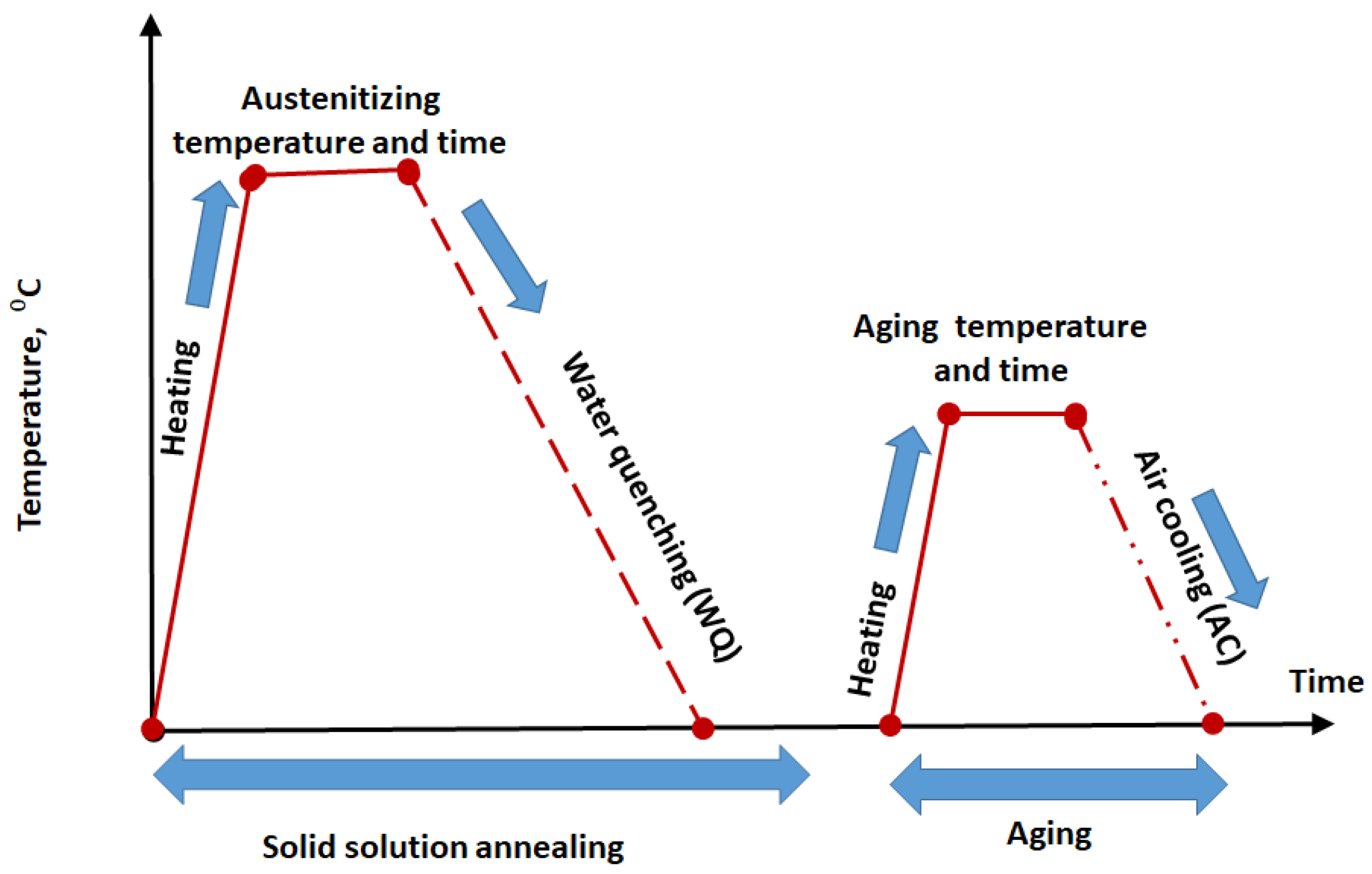
After interpretation of the data from DSC analysis, investigated steel sample follows the heat treatment scheme which consists of solid solution annealing step followed by cooling (furnace, air, or water) furthermore, aging step. Aging occurs at optimum temperature and time. The optimum condition of aging is the highest hardness value for the aging curve constructed through heating at 400, 450, 500, 550, 600 °C for three different periods of time e.g., 60, 120, 240 min. The solution heat treatment-aging scheme are shown in Figure 1.
2.4. X-ray Diffraction
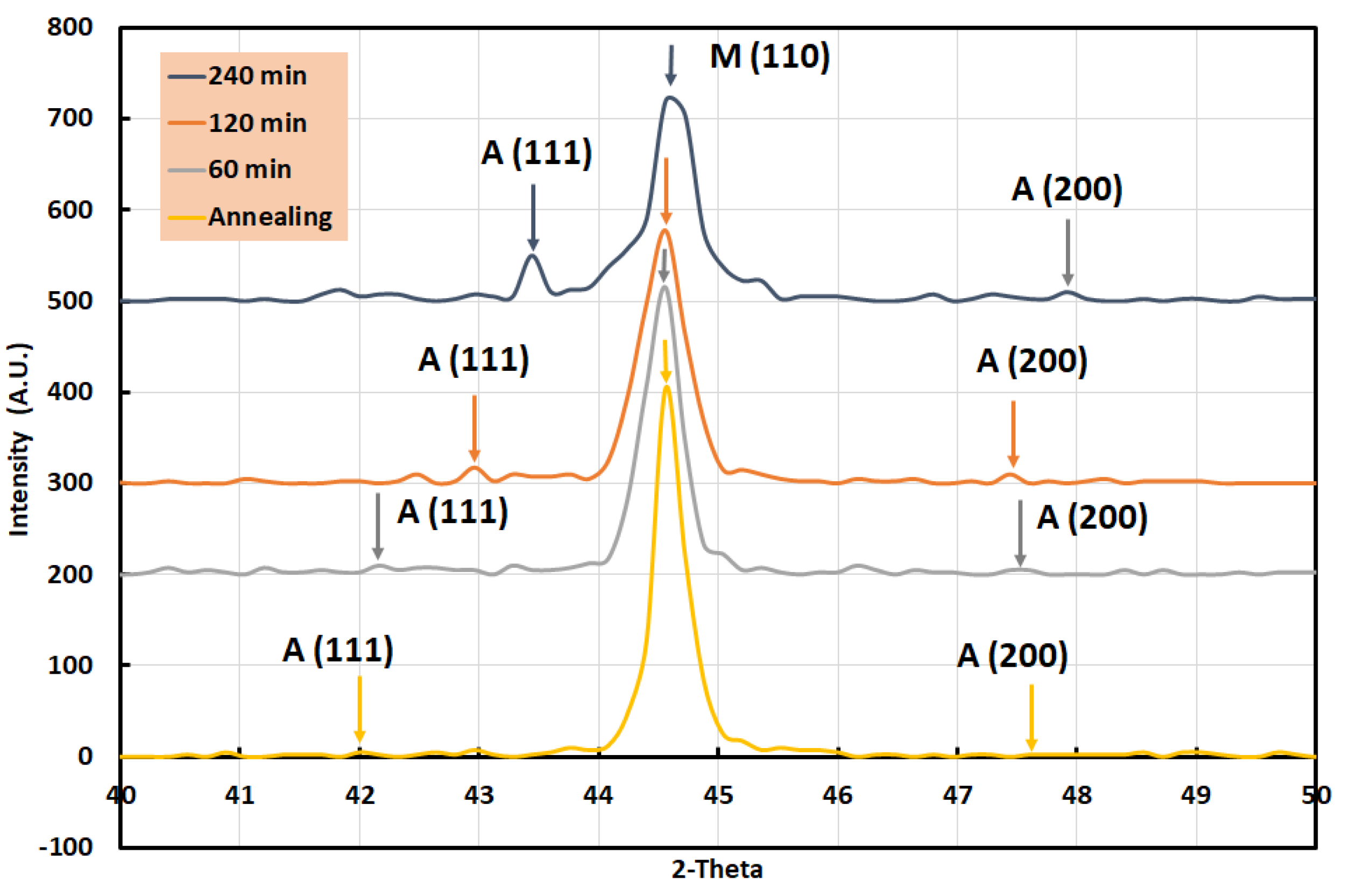
To complete the view of the microstructure of investigated steel samples, the volume fraction of existing phases was determined quantitively using the X-ray diffraction method. X-ray diffraction is an essential method to quantify the different phases especially retained austenite in bulk maraging steel specimens. BRUKER AXS D8-advance diffractometer (Bruker UK Ltd., Coventry, UK) utilized monochromatic Cu–Kα radiation (λ = 0.15406 nm) in the Bragg-Brentano configuration worked at 40 kV and 0.050 A which used to measure the X-ray diffraction (XRD) pattern. XRD patterns were documented with measuring step size of 0.02° and measuring step time of 1 s at each step. The fraction of γ-austenite, VA, was calculated mathematically by Equation (1) which was reported by Wang [32] and Li [33]:
where VA volume fraction of γ-austenite phase, IA average integrated intensity of γ-austenite phase from the (111)A and (200)A planes, IM integrated intensity of martensite phase from the (110)M planes.
VA = 1.4IA/(IM + 1.4IA)
2.5. Hardness and Tensile Testing
Microhardness of the samples was measured along the transverse plane using Vickers microhardness tester. In this process, 100 gm load was applied for 20 s.
The tensile samples used were in the form of cylinder. The proper surface polishing was carried out. The gauge length of the specimen was 20 mm whereas the diameter was 5 mm (in accordance with ASTM standards E 8). These specimens were fabricated in this shape after the ESR processing and forging. The tensile tests were carried out at room temperature (~28 °C) until failure at initial strain rate of 10−3 s−1. The testing equipment is a servo hydraulic power machine, which is controlled by a PC Strain measurements
2.6. EBSD Analysis
A PANalytical PANN alytical X’Pert Pro MRD goniometer (Malvern Panalytical Ltd, Malvern, UK) with a Cu tube running at 40 kV was used to test bulk texture. The specimen was machined and further polished mechanically to produce scratch-free and smooth surfaces before texture measurements. The texture test was conducted on samples’ 10 × 10 µm2 surfaces. In a FEI Quanta FEG 250 FESEM, the microstructures of the specimen were analysed using electron backscattering diffraction (EBSD). The sample for EBSD was electrolytically cleaned using 30 vol. percent HNO3 (nitric acid) methanol solution at −30 °C with a voltage of 14 V. Electro-polishing in an HClO4 + 900 mL CH3OH solution was used to polish the sample for EBSD analysis. A Zeiss Supra 55 VP FEGSEM ( Department of Physics University of Warwick, West Midlands CV4 7AL, Coventry, United Kingdom) with an orientation imaging micros-copy OIMTM device mounted on it was used for EBSD measurement. The mapping phase size and scan area were set to 100 nm and 100 × 100 µm2, respectively.
2.7. Transmission Electron Microscope (TEM)
A JEOL JEM 3010 TEM (Eurofins Nanolab Technologies, Milpitas, CA, USA) was used that operated at a 300 kV accelerating voltage. For TEM investigation a 3-mm disc with the thickness of 0.5 mm is taken from the cross segment of extruded billets (ED-plane) and mechanically ground down to around 15 µm thick foils for TEM investigations. Following that, 3 mm discs were inserted from the specimens and polished to perforation using a twin-jet electro polishing plant at −25 °C and 15 V using a solution of 30% nitric acid in methanol. From a 2 mm diameter area, selected area electron diffraction (SAED) patterns were taken.
3. Results
3.1. DSC Analysis
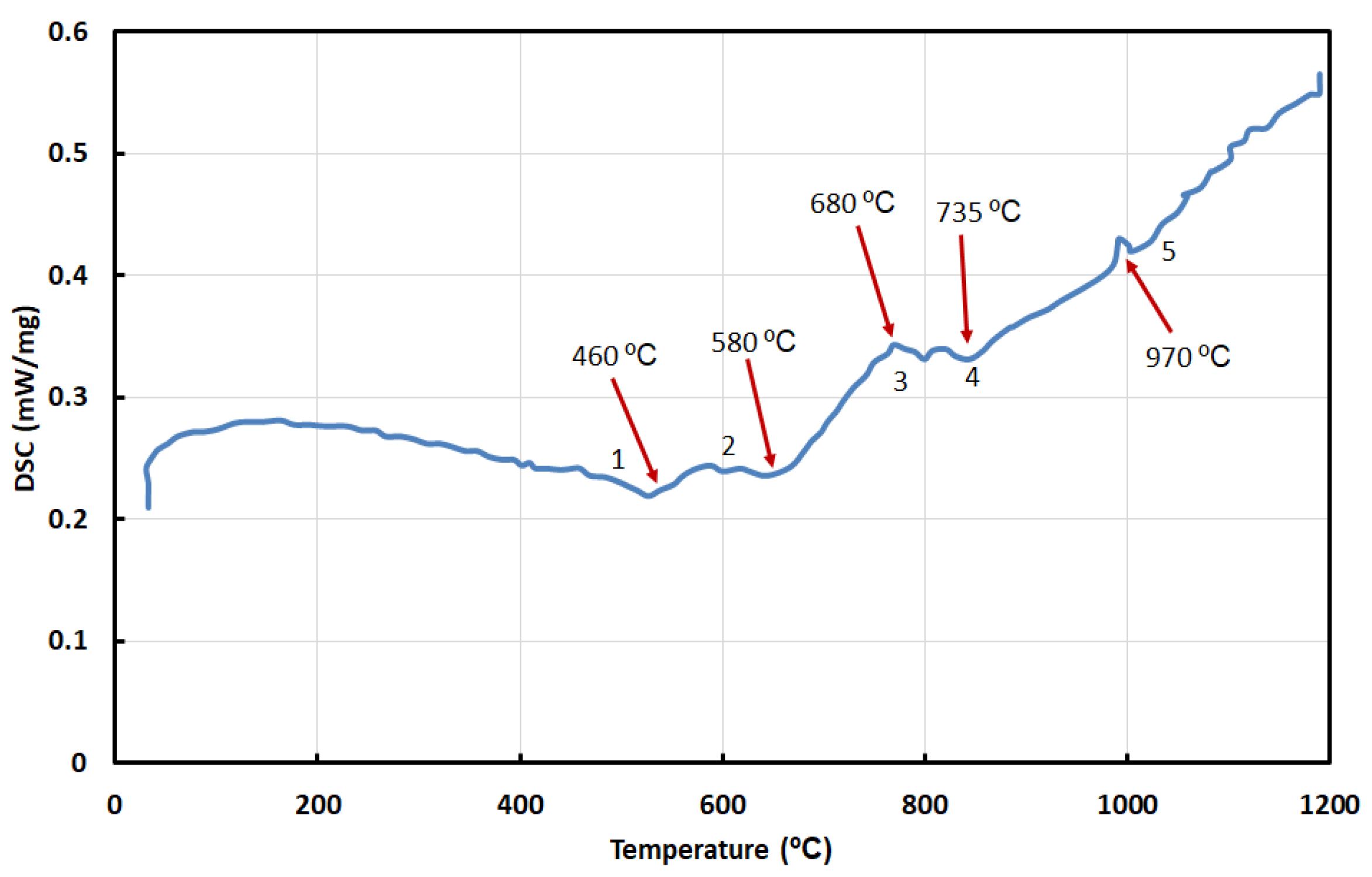
The DSC characteristic, which is related to the phase transition, senses both the phase transformation and precipitation phenomena of materials during heating. The DSC analysis of the as-received sample that was analysed is seen in Figure 2. On the DSC curve, the sample has five peaks. The primary exothermic peak (peak#1) is regularly related to grain development of retained austenite and the arrangement of the essential intermetallic accelerates, such as Ni3(Ti, Mo) phases that went with by the deterioration of Fe2Mo [10,34], whereas the moment exothermic peak (peak#2) is ordinarily related with carbide arrangement, coherent precipitation zones, or martensite recuperation [35]. From 675 to 825 K, Tewari et al. [3] discovered that Fe2Mo and Ni3(Ti, Mo) emerged in series as the temperature and holding time increased. The solution process is described by the last two peaks. In the high-temperature section, endothermic peaks #3 and #4 can be found. The previous is accepted to be caused by the decay of accelerates, whereas the last mentioned is thought to be caused by the stage move from α–phase (martensite, BCC-body cubic centred) to γ–phase (austenite, FCC-face cubic centred). Within the DSC curve for the specimen (peak#5), there are a few unsettling influences at high temperatures, which may be due to the presence of some impurities in form of oxides. The maraging steel’s aging temperature range is 400–600 °C, and the solid solution (austenitizing) temperature is above 970 °C, according to the DSC curve. However, it is well recognized that sample microsegregation is important and that the elements must disperse at a high temperature. As a result, the temperature in this work is raised to 1050 °C in order to allow a more reliable heat treatment.
3.2. Aging Behavior
In high Ti and Mo steels, Ti and Mo in solution and did not precipitate during both forging and solution treatment processes therefore both can precipitate during aging either as intermetallic compounds or carbides and nitrides causing intermetallic and non-metallic precipitation strengthening. To determine the aging behaviour of investigated steel, aging experiments were carried out after ST (950 °C/WQ), in the temperature range of 400 to 600 °C for 1, 2, and 4 h.
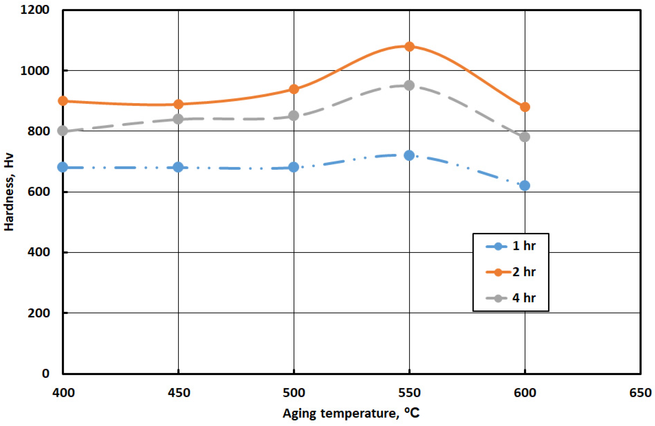
The hardness values, ductility, strength, and impact toughness of the experimental steel samples are the most meaningful technological properties that determine the steel behaviour. Hardness is the most often used property for testing and evaluation of steel. It is the simplest to proceed and is a fair indication of the properties of the material. Figure 3 illustrates the aging behaviour curves for M9.8 under investigation at different aging temperatures and at different times. The hardness of investigated steel increases as aging temperature increases, a widened peak hardness is obtained (as illustrated in Figure 3). Further increase in aging temperature above peak aging temperature is accompanied by decreasing in hardness (over-aging). The change of aging temperature and gain of hardness may be attributed to increasing the percentage of the intermetallic compound, changing in the percentage of retained austenite, and decreasing of grain size. The presence of these precipitates increases the strength and the hardness of the steel.
3.3. Microstructure of Full Heat Treated Water Quenched M9.8 Maraging Steel
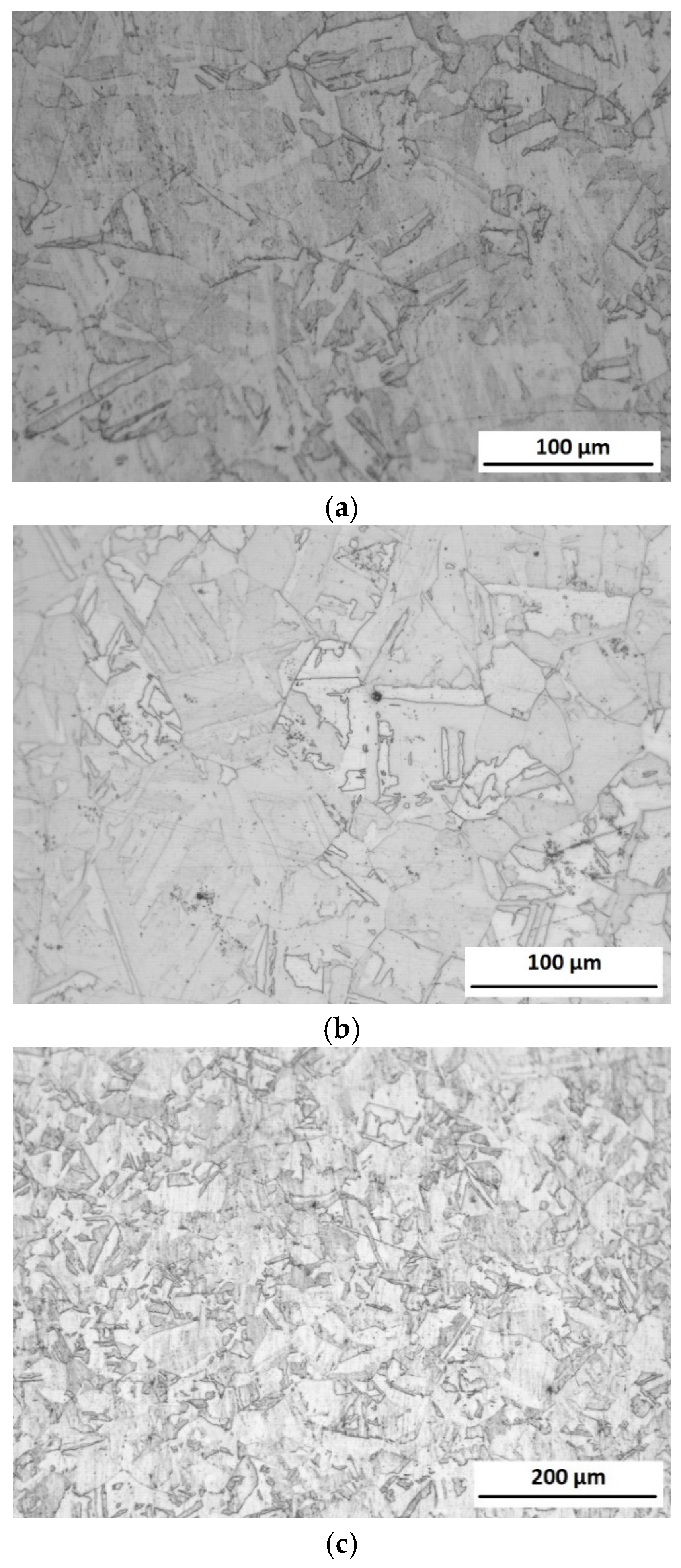
The SEM images of M9.8 WQ sample and aged at 550 °C with different holding times (60 min, 120 min, and 240 min) are given in Figure 4. Figure 4 indicates the typical martensitic microstructure which is characterized by a high density of dislocation in the maraging steel, without observation of retained austenite. It is clear that there are martensite laths with different orientations in the 550 °C/ 60 min sample, though the boundaries of martensite blocks are not easily distinguished due to lower aging temperature. The microstructure of 550 °C, 120 min steel exhibits an aged lathy martensite microstructure. However, the boundaries of blocks can be clearly identified; meanwhile, some blocks have been merged together because of the growth of martensite sub-grains. With increasing the holding time, 550 °C/ 240 min steel retains the elongated laths with discontinuous distribution, and the spacing of them becomes larger.
A marked increase in austenite content is induced by over-aging. It is expected that a further slight decomposition of martensite could be achieved by both increasing the aging temperature and holding time. In Figure 4, a collection of representative SEM micrographs is given. On aging, an increased amount of austenite (bright constituent in Figure 4) decorating cell boundaries became visible while over-aging additionally promoted precipitation of austenite at intragranular sites.
XRD was carried out to assess phase amounts in the investigated sample in both conditions after solid solution and after full heat treatment as shown in Figure 5. A marked increase in austenite content is induced by aging. It is expected that further slight decomposition of martensite could be achieved by also increasing the aging temperature and holding time. The result of the x-ray diffraction pattern emphasizes the result obtained by scanning electron microscope studies. The amount of % martensite variation with aging temperature and holding time are given in Table 2.
3.4. Mechanical Properties (Tensile Properties) of M9.86 Maraging Steel
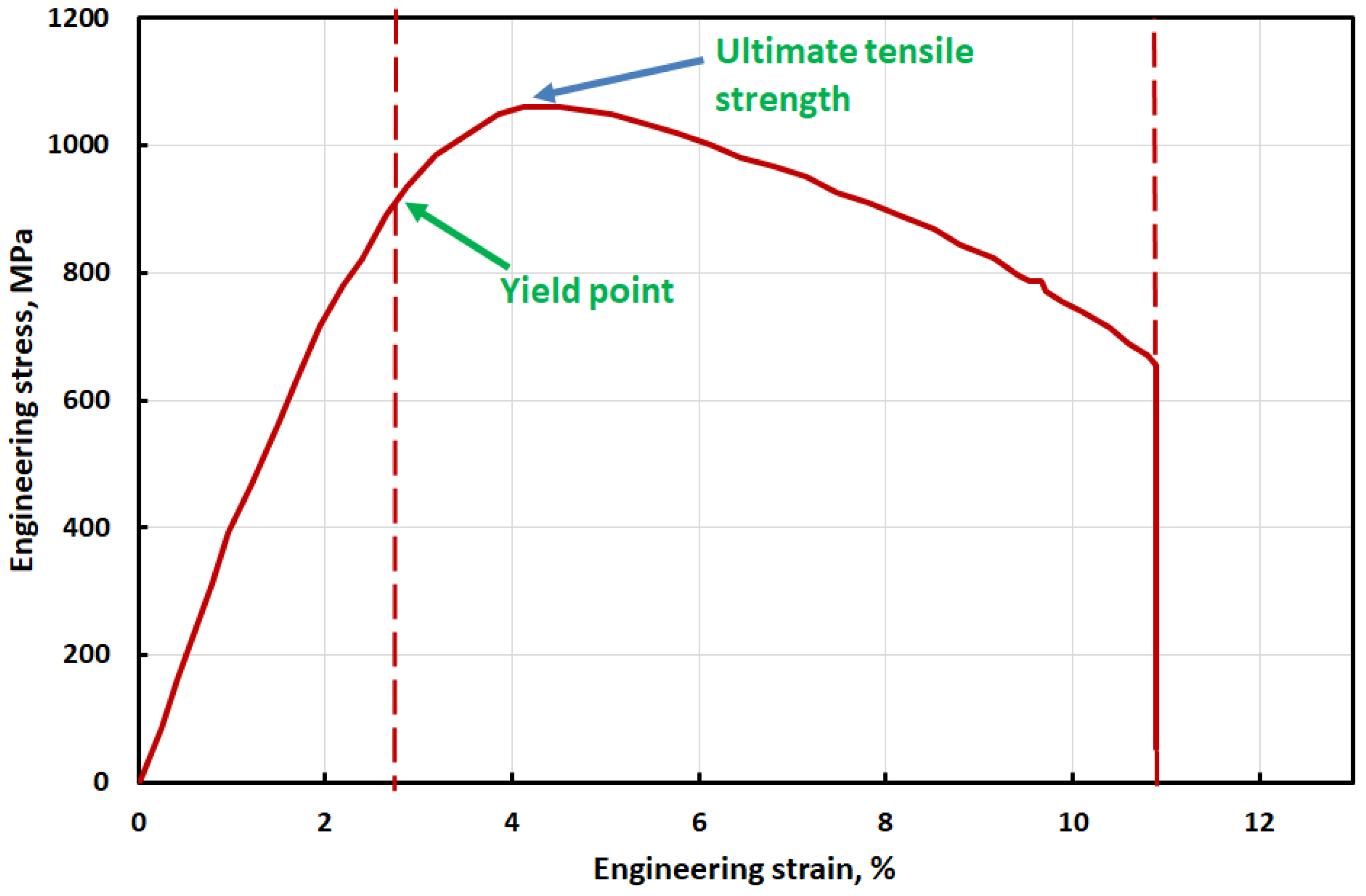
One of the character descriptions of maraging steel is that low ultimate and yield strength in solid solution annealing condition which helps the designer and manufacturer for machining and forming complex shapes in an easy way. The Tensile strength and Yield strength in solid solution annealing conditions are shown in Table 3. Figure 6 exhibits the engineering stress-strain curve at room temperature of solid solution annealing followed by WQ. Lowering in hardness and all tensile properties of investigated steel sample may be attributed to the presence of high alloyed lathe martensite phase with small amount of retained austenite phase.
Full capacity of tensile properties will gain after the aging process. Aging promotes the investigated steel sample to precipitate different kinds of intermetallic compounds such as NiTi3 and NiMo3. Precipitating this intermetallic compound leads to a decrease in the content of the alloying element of martensite and promotes precipitating retained austenite. The presence of these phases has a major effect on mechanical properties generally and both toughness and ductility especially.
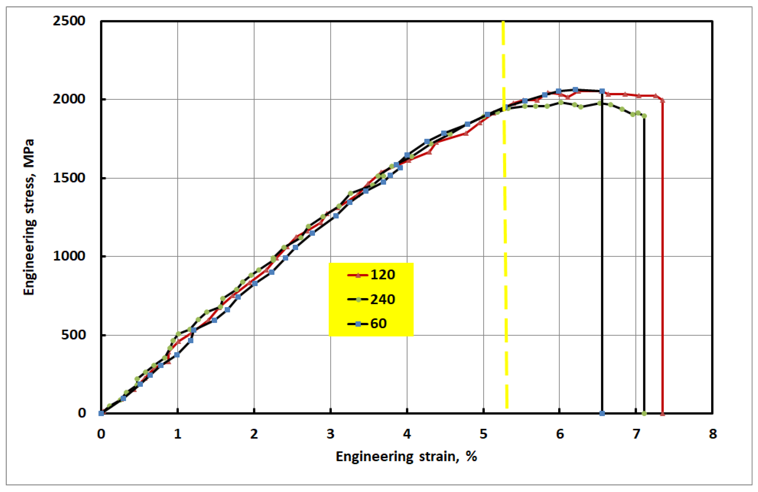
Figure 7 represents the engineering stress-strain curve of the full heat treated M9.86 WQ sample (solid solution annealing followed by WQ then aging at 550 °C withholding time 60, 120, and 240 min). Table 3 presents the tensile properties of M9.8 sample after complete heat treatment. Obtained high strength for M9.86WQ steel samples due to rapid precipitation of NiTi3 and NiMo3 at grain boundary which worked as obstacles to prevent both movements of grain boundaries as well as dislocations. Figure 7 shows the effect of aging time on the measured tensile properties of investigated steel samples. This figure shows that sample aged for 120 min at 550 °C represents both the highest ultimate tensile strength and highest strain % in comparison with samples aged at 60 min or 240 min at the same temperature (550 °C).
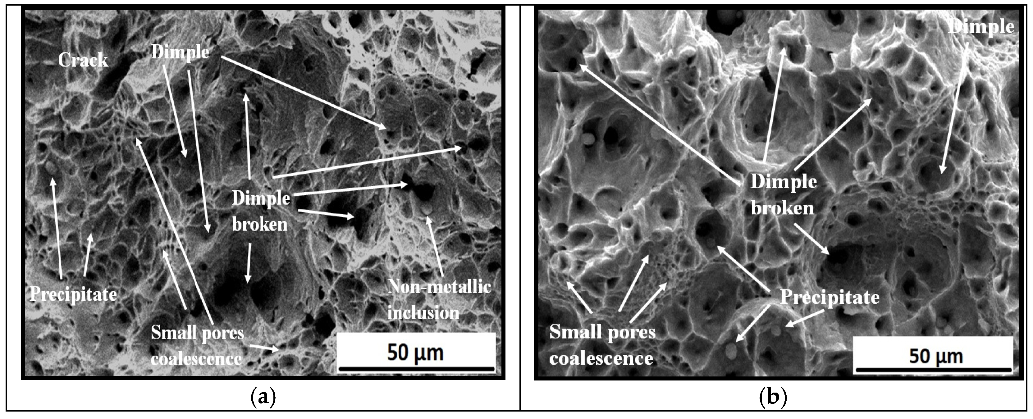
In order to understand the causes of the fracture, the low magnification of the scanning electron microscope was used to observe the fracture surface. Scanning electron microscopy (SEM) from the fracture surface after tension test shows that, for investigated steel samples, the ductile fracture surface is pro-dominated as shown in Figure 8. Figure 8 displays the tensile fracture morphology of the investigated steel samples. The fractured surface of M9.8 steel samples mainly consists of dimples and a small amount of cleavage fracture appears, in this circumstance, tensile properties and toughness are improved. The surface fracture morphology is reliable with the steel samples’ microstructure and properties. Many factors would affect the size of the dimples, such as the shape of the second-phase particles, material plasticity, deformation hardening index, stress, and temperature. At low load and low strain rate at the start of the tensile test regular dimples were formed inside the steel sample. Smaller and denser dimples gradually agglomerate around the dimples. When the stress reached ultimate value, these smaller and denser dimples were connected in a strip. When the stress increased beyond ultimate value smaller dimples disappeared, and some dimples had broken. The broken dimples were easy to form a fracture source, which might lead to the fracture and reduce the tensile properties of the specimens.
3.5. EBSD Analysis
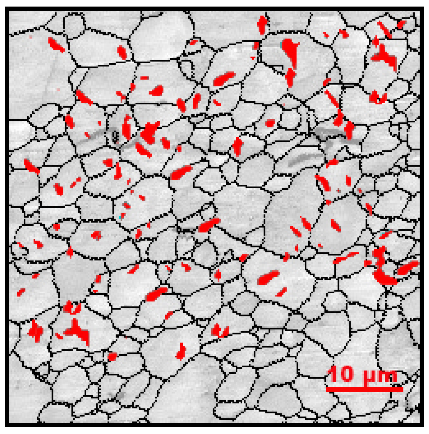
The experimental sample’s EBSD IQ-phase map is also seen in Figure 9. The high-angle grain boundary (HAGB) greater than 15°, which comprises of the various grain boundaries of earlier austenite grains, bundle, and block [20], is appeared by the dark lines. The nanoscale film-like reversed primarily locates at the HAGB after increasing the ageing temperature, and its resulting material is estimated to be 9.76 % percent by XRD.
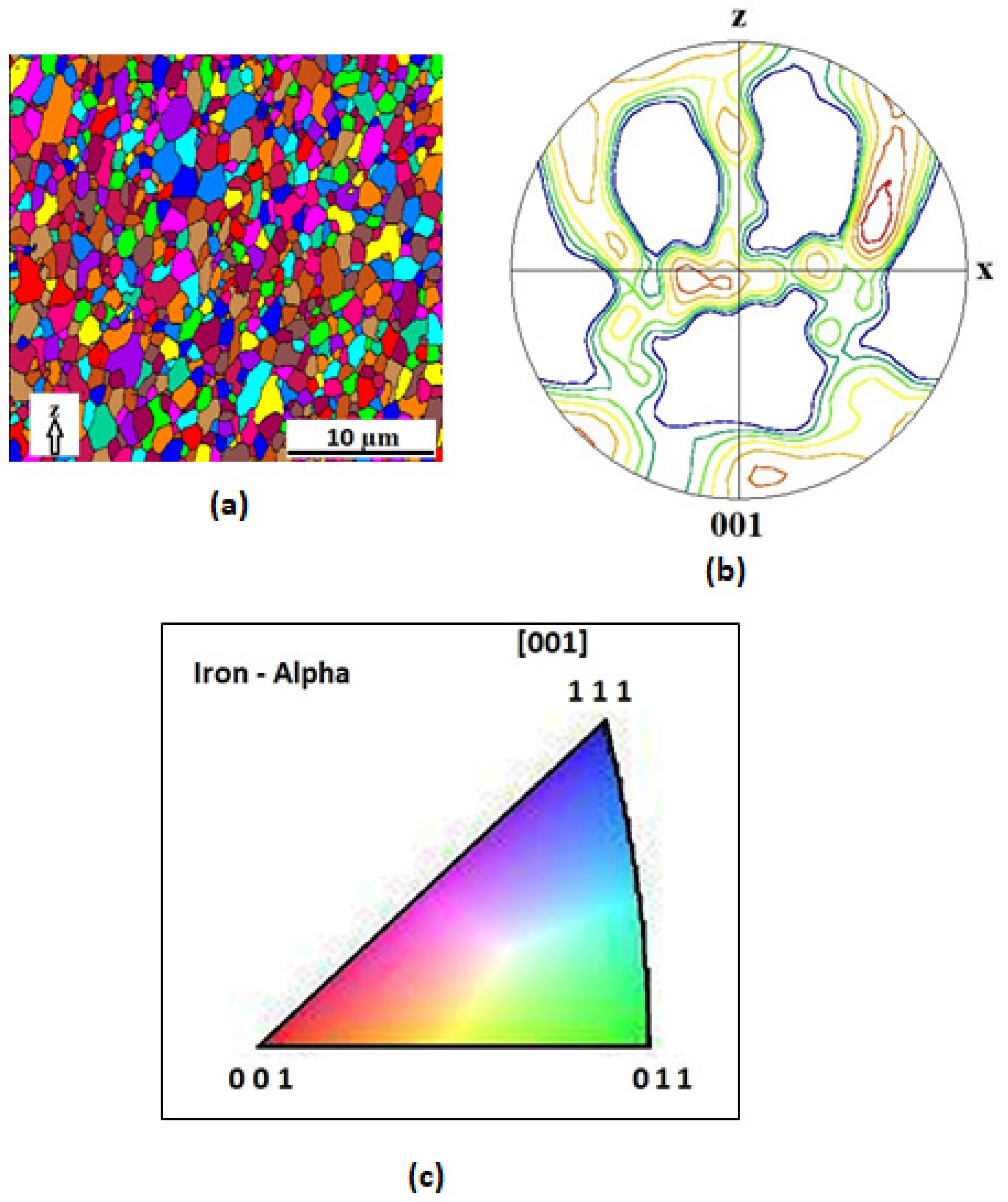
The EBSD of the M9.8WQ aged at 550 °C for 120 min is seen in Figure 10. A number of grains that were identified as fine austenite (γ) are scattered in a ferrite (α) network, agreeing to an EBSD observation of the melt-pool microstructure (Figure 10). Within the-Fe lattice, the preserved phases regularly showed up along grain boundaries. This result is in agreement with the findings of several studies published by different authors [36,37,38]. The fine grains which are identified as γ were particularly concentrated at the melt pool boundaries. The microstructural morphologies which are found within the preparation coordinated the lath martensite structure recognized by EBSD examinations [39,40], recommending that a martensite structure be shaped in this maraging steel. Most of the grains which are fine were aligned in the Z direction (Figure 10b), giving the retained process a [001] texture (Figure 10c).
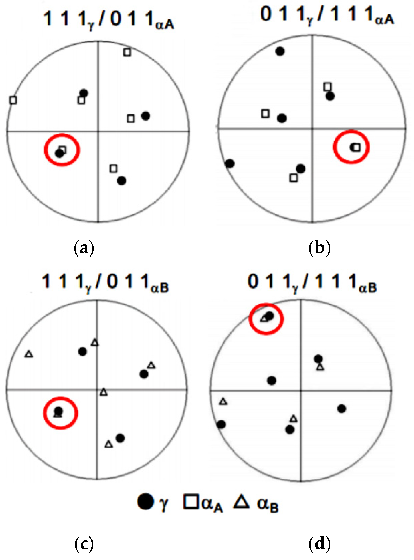
Figure 11a–d represents the stereographic representations of Figure 11a illustrating the low-index orientations produced by conducting the EBSD analyses. The arrangement relationship between the fine held grains adjusted along with the Z heading and the neighbouring grains within the martensite structure was found by EBSD investigation (Figure 11a). The fine grain has an orientation relation of (111)//(011) and [ī0ı]//[ī ī ı] with respect to the adjacent grain, as seen in the stereographic projections (Figure 11a,b). With respect to another grain, the stereographic projections (Figure 11c,d) reflect the fine grain as having a separate version of (111)//(011) and [ī0ı]//[ī ī ı]. The decided introduction relationship is steady with the crystallographic highlights of the lath martensite structure in ordinarily extinguished maraging steels [41] and connects to the Kurdjumov–Sachs (K–S) introduction relationship between the austenite and lath martensite [9].
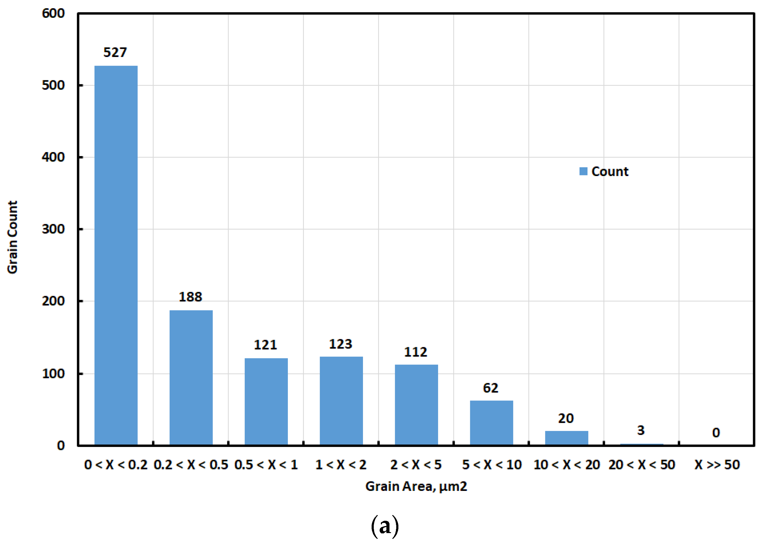
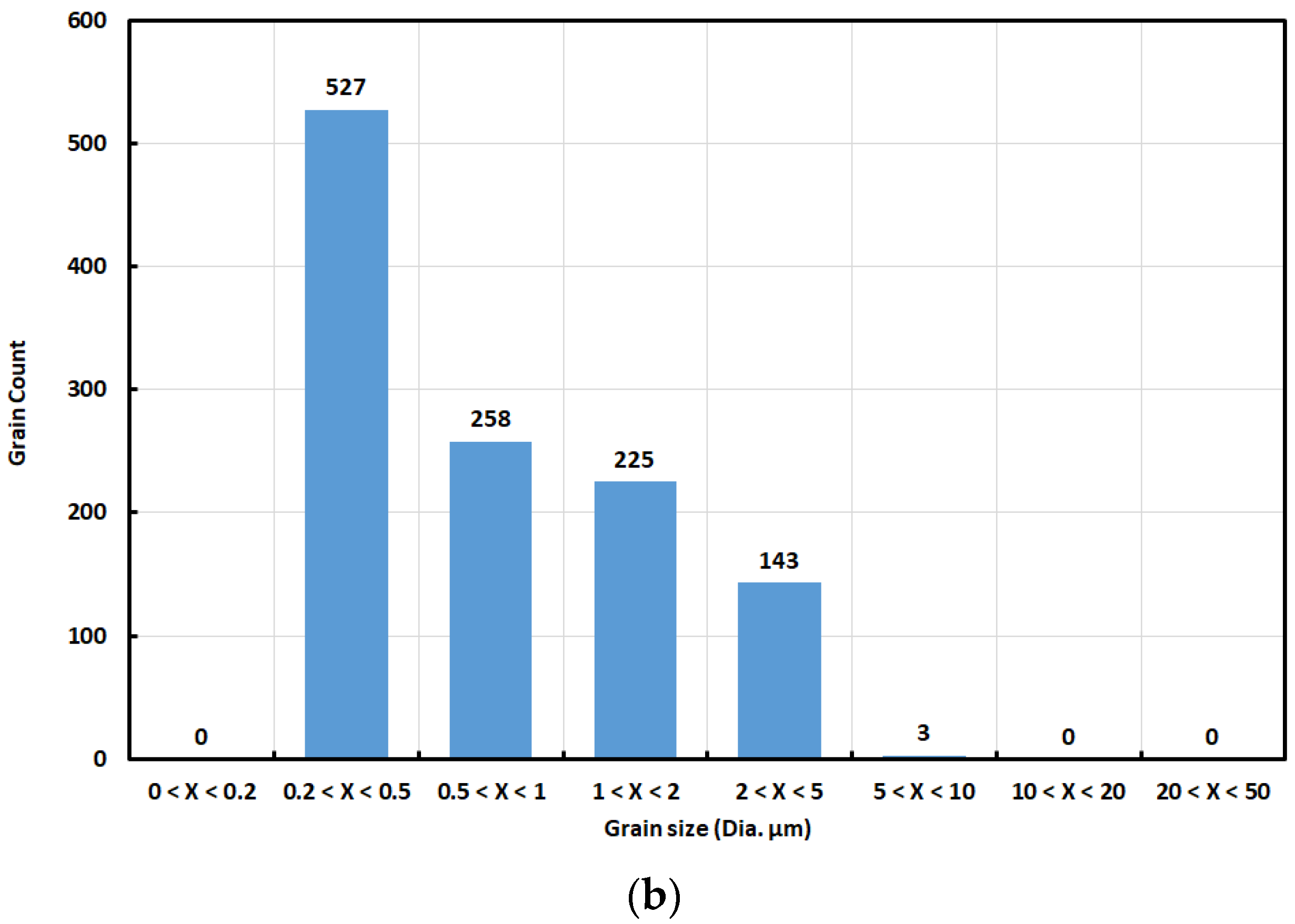
Although the investigated steel has ultrahigh high strength value, it has high toughness and ductility. Figure 12 presented the count distribution of grains with their size in Figure 12a furthermore its area in Figure 12b. This Figure shows that the investigated steel has fine grain lower than 2 μm with a count percent of about 68% of the total count of presented grains. On the other hand, the total count of gains with an area lower than 2 μm2 reached 959 grains, around 83% of the occupied total area. Deep analysis of count and size distribution of grains in M9.8 steel samples show the formation of new grains or sub-grains with minute size, as shown in Figure 12. The newly formed grains are well distributed along the grain boundaries and have a high dislocation density. The formed microstructure affected all tensile and toughness properties through high dislocation density and high grains boundaries.
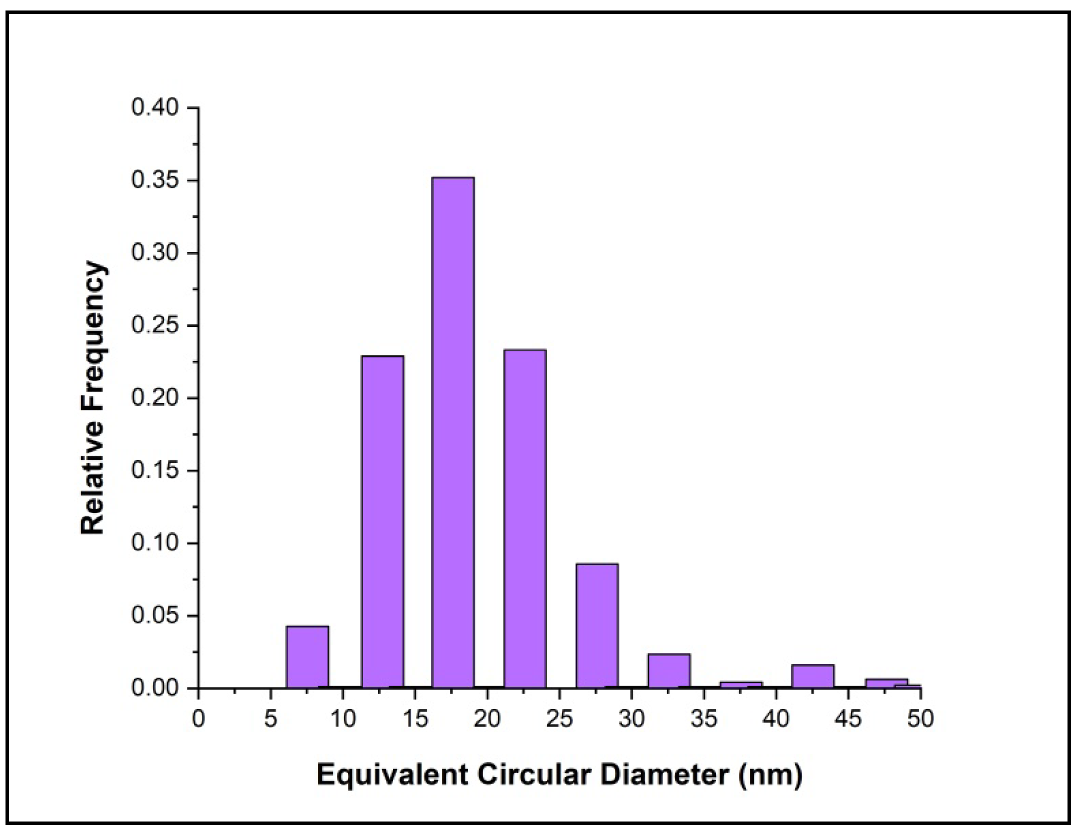
The histogram plot of M9.8WQ aged at 550 °C for 120 min is shown in Figure 13. The final microstructure includes small secondary Mo precipitates with a mean diameter of 19 ± 1 nm and narrower size distribution, as seen in Figure 13. In conclusion, Mo-rich phase precipitates are found in this sample, with distinctly different sizes. In this sample, no Laves precipitate (Mo, Cr) is observed after austenisation, and only after aging do the small secondary Laves phase precipitates form in the microstructure, located both within the martensite laths and along the lath boundaries.
3.6. TEM Analysis
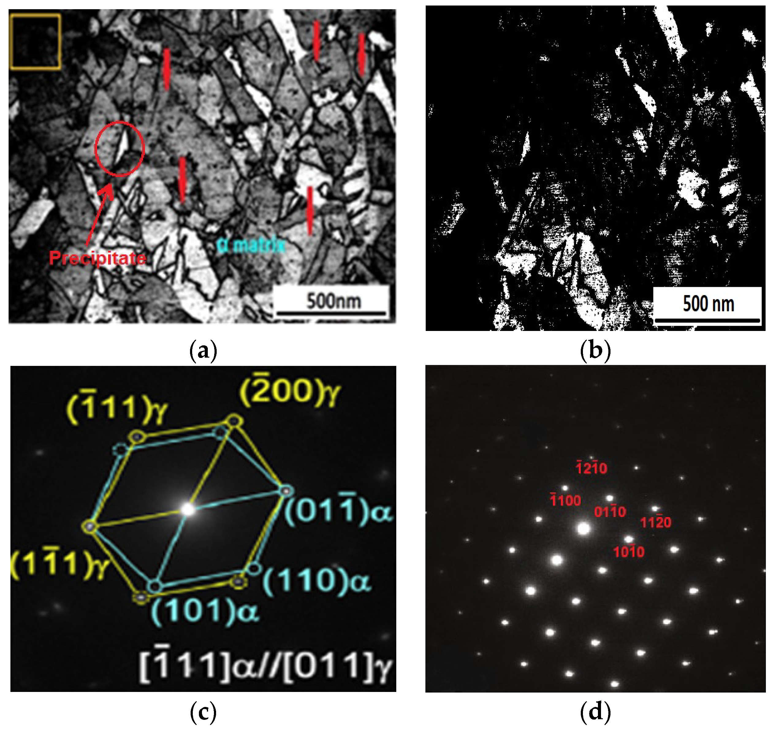
The average precipitate scale was found to be about 40 nm in length and 2.5 nm in thickness. The size of the precipitates was measured using Image J software. The red marked portion in Figure 14a exhibits some of the precipitates. The precipitates, considering their limited scale, were observed to have a range of fringe contrast, as seen in the dark field images (Figure 14b) obtained using precipitate reflections. These fringes were discovered to be parallel to the length of the precipitates for certain electron beam directions. Some globular Fe2Mo precipitates were observed here. In Figure 14c it denoted by α and ϒ phase. The η phase present in the structure is denoted by the yellow portion in Figure 14c. The SAED pattern of that yellow portion is given in Figure 14d. The SAED pattern obtained from the matrix revealed that the presence of intermetallic compounds is defined as η phase and precipitates equally embedded in the matrix. Diffraction pattern, SAED analysis revealed that the matrix of sample M9.8 steel is composed of austenite moreover martensite as shown in Figure 14d. TEM result shows that the investigated steel M9.8 specimen microstructure consists of a γ phase (austenite) and α phase (martensite) with a single η phase.
However, the fringes of some precipitates were found to be perpendicular to their length. The hexagonal, Ni3Ti form, eta (η) step with lattice parameters a = 0.5101 nm and c = 0.8307 nm could be indexed in terms of the SAED patterns (Figure 14c) from the precipitates in this study. Since this phase also includes Mo, it will be referred to as Ni (Titanium, Molybdenum): Ni3(Ti, Mo) phase [42].
4. Conclusions
- Electroslag remelting process is a successful production method for producing steel with high technological properties through the production of very low microsegregation steel and clean steel (e.g., large non-metallic inclusion not fewer nanometers) as well as small grain sizes.
- Phase and precipitation temperature of investigated steel obtain in appreciation of DSC. DSC result shows that intermetallic compound may be precipitate at 550 °C. While the austenitization temperature of this steel sample must be more than 970 °C.
- Investigated steel samples exhibit high tensile properties and ductile fracture may be attributed to high density with nanoscale intermetallic compound. This intermetallic compound pining dislocation movement and coalescence.
- Nanoscale film-like reversed γ after increasing aging temperature, primarily at the HAGB. Larger blocky reversed γ forms in martensite blocks Moreover, the content of reversed γ remarkably increases to 17.2 vol.%.
- A number of grains which is fine austenite (γ) are dispersed in a ferrite (α) matrix, according to an EBSD study of the melt-pool microstructure. In the α-Fe matrix, the preserved phases often come out along grain boundaries.
- The fine γ grain has an orientation association of (111)γ//(011)α and [ī0ı] γ //[ī ī ı] α with respect to the neighbouring grain, as seen by the stereo-graphic projections. With respect to another grain, the stereographic projections reflect the fine γ grain has a separate version of (111)γ//(011)α and [ī0ı] γ //[ī ī ı] α.
- The density of dislocations reduces, and the martensite lath borders steadily fade away, with the film-like reversed γ observed at the inter-laths.
Author Contributions
Conceptualization, A.H.S., H.H. and M.S.S. Data curation, A.H.S., H.H. and M.S.S. Formal analysis, A.H.S., H.H. and M.S.S. Funding acquisition, M.S.S. Investigation, A.H.S. and M.S.S. Methodology, A.H.S., H.H. and M.S.S. Resources, H.H. Supervision, A.H.S., H.H. and M.S.S. Writing (original draft), A.H.S., H.H. and M.S.S. Writing (review and editing), A.H.S., H.H. and M.S.S. All authors have read and agreed to the published version of the manuscript.
Funding
This work was funded by the National Plan for Science, Technology and Innovation (MAARIFAH), King Abdul-Aziz City for Science and Technology, Kingdom of Saudi Arabia, grant number (12-ADV2465-02).
Institutional Review Board Statement
Not applicable.
Informed Consent Statement
Not applicable.
Data Availability Statement
The experimental datasets obtained from this research work and then the analysed results during the current study are available from the corresponding author on reasonable request.
Conflicts of Interest
The authors declare no conflict of interest.
References
- Williams, J.C.; Starke, E.A., Jr. Progress in structural materials for aerospace systems. Acta Mater. 2003, 51, 5775–5799. [Google Scholar] [CrossRef]
- Liu, P.; Stigenberg, A.H.; Nilsson, J.O. Quasicrystalline and crystalline precipitation during isothermal tempering in a 12Cr-9Ni-4Mo maraging stainless steel. Acta Metall. Mater. 1995, 43, 2881–2890. [Google Scholar] [CrossRef]
- Tewari, R.; Mazumder, S.; Batra, I.S.; Dey, G.K.; Banerjee, S. Precipitation in 18 wt% Ni maraging steel of grade 350. Acta Mater. 2000, 48, 1187–1200. [Google Scholar] [CrossRef]
- Garrison, W.M., Jr. Ultrahigh-strength steels for aerospace applications. JOM 1990, 42, 20–24. [Google Scholar] [CrossRef]
- Sha, W.; Guo, Z. Maraging Steels: Modelling of Microstructure, Properties and Applications; Woodhead Publishing: Oxford, UK; CRC Press: Boca Raton, FL, USA, 2009. [Google Scholar]
- Carvalho, L.G.; Andrade, M.S.; Plaut, R.L.; Souza, F.M.; Padilha, A.F. A dilatometric study of the phase transformations in 300 and 350 maraging steels during continuous heating rates. Mater. Res. 2013, 16, 740–744. [Google Scholar] [CrossRef] [Green Version]
- Pardal, J.M.; Tavares, S.S.M.; Terra, V.F.; da Silva, M.R.; dos Santos, D.R. Modeling of precipitation hardening during the aging and overaging of 18Ni-Co-Mo-Ti maraging 300 steel. J. Alloys Compd. 2015, 393, 109–113. [Google Scholar] [CrossRef]
- Sha, W.; Cerezo, A.; Smith, G.D.W. Phase Chemistry and Precipitation Reactions in Maraging Steels: Part I. Introduction and Study of Co-Containing C-300 Steel. Metall. Trans. A 1993, 24A, 1221–1232. [Google Scholar] [CrossRef]
- Pardal, J.M.; Tavares, S.S.M.; Fonseca, M.P.C.; Abreu, H.F.G.; Silva, J.J.M. Study of the austenite quantification by X-ray diffraction in the 18Ni-Co-Mo-Ti maraging 300 steel. J. Mater. Sci. 2006, 41, 2301–2307. [Google Scholar] [CrossRef]
- Guo, Z.; Sha, W.; Li, D. Quantification of phase transformation kinetics of 18 wt.% Ni C250 maraging steel. Mater. Sci. Eng. A 2004, 373, 10–20. [Google Scholar] [CrossRef]
- Jägle, E.A.; Choi, P.P.; van Humbeeck, J.; Raabe, D. Precipitation and austenite reversion behavior of a maraging steel produced by selective laser melting. J. Mater. Res. 2014, 29, 2072–2079. [Google Scholar] [CrossRef] [Green Version]
- Li, X.; Yin, Z. Reverted austenite during aging in 18Ni (350) maraging steel. Mater. Lett. 1995, 24, 239–242. [Google Scholar] [CrossRef]
- Viswanathan, U.K.; Dey, G.K.; Sethumadhavan, V. Effects of austenite reversion during overageing on the mechanical properties of 18 Ni (350) maraging steel. Mater. Sci. Eng. A 2005, 398, 367–372. [Google Scholar] [CrossRef]
- Tavares, S.S.M.; Abreu, H.F.G.; Neto, J.M.; da Silva, M.R.; Popa, I. A thermomagnetic study of the martensite-austenite phase transition in the maraging 350 steel. J. Alloys Compd. 2003, 358, 152–156. [Google Scholar] [CrossRef]
- Bai, Y.; Wang, D.; Yang, Y.; Wang, H. Effect of heat treatment on the microstructure and mechanical properties of maraging steel by selective laser melting. Mater. Sci. Eng. A 2019, 760, 105–117. [Google Scholar] [CrossRef]
- Xu, X.; Ganguly, S.; Ding, J.; Dirisu, P.; Martina, F.; Liu, X.; Williams, S.W. Improving mechanical properties of wire plus arc additively manufactured maraging steel through plastic deformation enhanced aging response. Mater. Sci. Eng. A 2019, 747, 111–118. [Google Scholar] [CrossRef] [Green Version]
- Wang, G.; Yan, Y.; Li, J.; Huang, J.; Qiao, L.; Volinsky, A.A. Microstructure effect on hydrogen-induced cracking in TM210 maraging steel. Mater. Sci. Eng. A 2013, 586, 142–148. [Google Scholar] [CrossRef]
- Xu, X.; Ganguly, S.; Ding, J.; Guo, S.; Williams, S.; Martina, F. Microstructural evolution and mechanical properties of maraging steel produced by wire+arc additive manufacture process. Mater. Charact. 2018, 143, 152–162. [Google Scholar] [CrossRef]
- da Silva, M.J.G.; Cardoso, J.L.; Carvalho, D.S.; Santos, L.P.; Herculano, L.F.G.; de Abreu, H.F.G.; Pardal, J.M. Thr effect of prior austenite grain size on hydrogen embrittlement of Co-containing 18Ni300 maraging steel. Int. J. Hydrog. Energy 2019, 44, 18606–18615. [Google Scholar] [CrossRef]
- Gao, Q.; Liu, Z.; Li, H.; Zhang, H.; Jiang, C.; Hao, A.; Qu, F.; Lin, X. High-temperature oxidation behavior of modified 4Al alumina-forming austenitic steel: Effect of cold rolling. J. Mater. Sci. Technol. 2021, 68, 91–102. [Google Scholar] [CrossRef]
- Zhang, S.; Wan, J.; Zhao, Q.; Liu, J.; Huang, F.; Huang, Y.; Li, X. Dual role of nanosized NbC precipitates in hydrogen embrittlement susceptibility of lath martensitic steel. Corros. Sci. 2020, 164, 108345. [Google Scholar] [CrossRef]
- He, Y.; Yang, K.; Sha, W. Microstructure and mechanicalproperties of a 2000 MPa grade co-free maraging steel. Metall. Mater. Trans. A 2005, 36, 2273–2287. [Google Scholar] [CrossRef]
- Sha, W.; Guo, Z. Maraging Steels; Woodhead Publishing: Sawston, UK, 2009; 216p. [Google Scholar] [CrossRef]
- Wang, M.-M.; Tasan, C.C.; Ponge, D.; Kostka, A.; Raabe, D. Smaller isless stable: Size effects on twinning vs. transformation ofreverted austenite in TRIP-maraging steels. Acta Mater. 2014, 79, 268–281. [Google Scholar] [CrossRef]
- Cao, H.; Luo, X.; Zhan, G.; Liu, S. Effect of intercritical quenchingon the microstructure and cryogenic mechanical propertiesof a 7 pct Ni steel. Metall. Mater. Trans. A 2017, 48, 4403–4410. [Google Scholar] [CrossRef]
- Li, Y.; Li, W.; Liu, W.; Wang, X.; Hua, X.; Liu, H.; Jin, X. The austenitereversion and co-precipitation behavior of an ultra-lowcarbon medium manganese quenching-partitioning-tempering steel. Acta Mater. 2018, 146, 126–141. [Google Scholar] [CrossRef]
- Zhao, X.; Pan, T.; Wang, Q.; Su, H.; Yang, C.; Yang, Q. Effect oftempering temperature on microstrueture and mechanicalproperties of steel containing Ni of 9%. J. Iron Steel Res. Int. 2011, 18, 47–51. [Google Scholar] [CrossRef]
- Sun, C.; Liu, S.L.; Misra, R.D.K.; Li, Q.; Li, D.H. Influence of intercriticaltempering temperature on impact toughness of a quenchedand tempered medium-Mn steel: Intercritical temperingversus traditional tempering. Mater. Sci. Eng. A 2018, 711, 484–491. [Google Scholar] [CrossRef]
- Hou, H.; Li, H.; Jin, Y.; Wang, X.; Wen, Z. Effect of heat treatmenttemperature on the mechanical properties of low-temperature high strength maraging steel. Mater. Sci. Eng. A 2014, 601, 1–6. [Google Scholar] [CrossRef]
- Hou, H.; Qi, L.; Zhao, Y.H. Effect of austenitizing temperature onthe mechanical properties of high-strength maraging steel. Mater. Sci. Eng. A 2013, 587, 209–212. [Google Scholar] [CrossRef]
- Halfa, H.; Fathy, A.; Kamal, M.; Eissa, M.; El-Fawahkry, K. Enhancement of mechanical properties of developed Ti-containing Co-free low-Ni maraging steel by ESR. Steel Grips 2010, 8, 278–284. [Google Scholar]
- Wang, Z.C.; Kim, S.J.; Lee, C.G.; Lee, T.H. Bake-Hardening Behaviour of Cold-Rolled CMnSi and CMnSiCu TRIP-Aided Steel Sheets. J. Mater. Process. Technol. 2004, 151, 141–145. [Google Scholar] [CrossRef]
- Li, Z.; Wu, D. Effects of Hot Deformation and Subsequent Austempering on the Mechanical Properties of Si-Mn TRIP Steels. ISIJ Int. 2006, 46, 121–128. [Google Scholar] [CrossRef] [Green Version]
- Decker, R.F. Source Book on Maraging Steels: A Comprehensive Collection of Outstanding Articles from the Periodical and Reference Literature; American Society for Metals, Metals Park: Novelty, OH, USA, 1979; Volume 1979, p. 399. [Google Scholar]
- Pereloma, E.V.; Shekhter, A.; Miller, M.K.; Ringer, S.P. Ageing behaviour of an Fe–20Ni–1.8 Mn–1.6 Ti–0.59 Al (wt%) maraging alloy: Clustering, precipitation and hardening. Acta Mater. 2004, 52, 5589–5602. [Google Scholar] [CrossRef]
- Kempen, K.; Yasa, E.; Thijs, L.; Kruth, J.P.; Humbeeck, J.V. Microstructure and mechanical properties of Selective Laser Melted 18Ni-300 steel. Phys. Procedia 2011, 12, 255–263. [Google Scholar] [CrossRef] [Green Version]
- Casati, R.; Lemke, J.N.; Tuissi, A.; Vedani, M. Aging Behaviour and Mechanical Performance of 18-Ni 300 Steel Processed by Selective Laser Melting. Metals 2016, 6, 218. [Google Scholar] [CrossRef]
- Morito, S.; Huang, X.; Furuhara, T.; Maki, T.; Hansen, N. The morphology and crystallography of lath martensite in alloy steels. Acta Mater. 2006, 54, 5323–5331. [Google Scholar] [CrossRef]
- Jägle, E.A.; Sheng, Z.; Kürnsteiner, P.; Ocylok, S.; Weisheit, A.; Raabe, D. Comparison of Maraging Steel Micro- and Nanostructure Produced Conventionally and by Laser Additive Manufacturing. Materials 2018, 10, 8. [Google Scholar] [CrossRef] [Green Version]
- Kitahara, H.; Ueji, R.; Tsuji, N.; Minamino, Y. Crystallographic features of lath martensite in low-carbon steel. Acta Mater. 2006, 54, 1279–1288. [Google Scholar] [CrossRef]
- DebRoy, T.; Wei, H.L.; Zuback, J.S.; Mukherjee, T.; Elmer, J.W.; Milewski, J.O.; Beese, A.M.; Wilson-Heid, A.; De, A.; Zhang, W. Additive manufacturing of metallic components—Process, structure and properties. Prog. Mater. Sci. 2018, 92, 112–224. [Google Scholar] [CrossRef]
- Reda, A.M.; Halfa, H. Evaluation of relatively low strength maraging steel. Int. J. Adv. Res. 2014, 2, 59–75. [Google Scholar]
Figure 1.
Heat treatment cycle of investigated steel samples.

Figure 2.
DSC curve of maraging steel of M9.8.

Figure 3.
HV for maraging steel (M9.8) under investigation at different aging temperatures and at different times.
Figure 3.
HV for maraging steel (M9.8) under investigation at different aging temperatures and at different times.

Figure 4.
SEM images of M9.8 WQ sample for (a) 550 °C, 60 min, (b) 550 °C, 120 min, (c) 550 °C, 240 min.
Figure 4.
SEM images of M9.8 WQ sample for (a) 550 °C, 60 min, (b) 550 °C, 120 min, (c) 550 °C, 240 min.

Figure 5.
XRD pattern of M9.8 sample in annealing + water quenching and aging conditions at 550 °C for 60, 120, and 120 min., respectively.
Figure 5.
XRD pattern of M9.8 sample in annealing + water quenching and aging conditions at 550 °C for 60, 120, and 120 min., respectively.

Figure 6.
Engineering Stress strain curve of M9.8 sample solid solution annealing followed by WQ.

Figure 7.
Stress strain curve of M9.8 WQ/aged samples with different holding time 60 min, 120 min and 240 min.
Figure 7.
Stress strain curve of M9.8 WQ/aged samples with different holding time 60 min, 120 min and 240 min.

Figure 8.
Room temperature tensile fractograph of M9.8 WQ sample aged at 550 °C for (a) 240 min and (b) 120 min.
Figure 8.
Room temperature tensile fractograph of M9.8 WQ sample aged at 550 °C for (a) 240 min and (b) 120 min.

Figure 9.
EBSD IQ phase map of M9.8WQ sample aged at 550 °C for 120 min.

Figure 10.
(a) orientation colour map of the α and γ phase (b) stereographic projection of the 001 poles in the γ phase (c) Plane of colour map.
Figure 10.
(a) orientation colour map of the α and γ phase (b) stereographic projection of the 001 poles in the γ phase (c) Plane of colour map.

Figure 11.
Stereographic projection of the 111γ /011α (a,c) and 011γ /111α (b,d) poles.

Figure 12.
Grain size at (a) and area distributions at (b) of heat-treated steel M9.8 sample.


Figure 13.
Histogram plot of Mo precipitate for M9.8 WQ aged at 550 °C for 120 min.

Figure 14.
TEM images Aged maraging steel sample (a) bright field (b) dark field and (c) corresponding SAED pattern of intermetallic compound, (d) secondary diffraction pattern (SAED) pattern of matrix.
Figure 14.
TEM images Aged maraging steel sample (a) bright field (b) dark field and (c) corresponding SAED pattern of intermetallic compound, (d) secondary diffraction pattern (SAED) pattern of matrix.


Table 1.
Chemical Composition of M9.8 steel.
| Al | Si | Mn | S | Ni | Ti | Mo | P | Cr | C | Fe |
|---|---|---|---|---|---|---|---|---|---|---|
| 0.081 | 0.084 | 0.12 | 0.015 | 10.8 | 1.24 | 9.8 | 0.009 | 4.75 | 0.025 | Bal. |
Table 2.
Martensite % value after heat treatment.
| Condition | Holding Time | % Martensite (XRD) |
|---|---|---|
| Annealing + WQ | 180 | 97.50 |
| Aging at 550 °C | 60 min | 94.03 |
| 120 min | 90.24 | |
| 240 min | 52.38 |
Table 3.
Tensile properties M9.8 sample at solid solution annealing followed by WQ.
| Treatment | Aging Time (min) | Hardness (Hv) | Tensile Strength (MPa) | Yield Strength (MPa) | Elongation, % |
|---|---|---|---|---|---|
| Solid solution—WQ | - | 550 | 1060 | 907 | 11 |
| Solid solution—WQ—aged at 550 °C | 60 | 720 | 1983 | 1905 | 6.6 |
| 120 | 1080 | 2041 | 1950 | 8.3 | |
| 240 | 950 | 2063 | 1970 | 7.1 |
Publisher’s Note: MDPI stays neutral with regard to jurisdictional claims in published maps and institutional affiliations. |
© 2021 by the authors. Licensee MDPI, Basel, Switzerland. This article is an open access article distributed under the terms and conditions of the Creative Commons Attribution (CC BY) license (https://creativecommons.org/licenses/by/4.0/).
Share and Cite
MDPI and ACS Style
Seikh, A.H.; Halfa, H.; Soliman, M.S. Evaluation of Strength and Microstructural Properties of Heat Treated High-Molybdenum Content Maraging Steel. Crystals 2021, 11, 1446. https://doi.org/10.3390/cryst11121446
AMA Style
Seikh AH, Halfa H, Soliman MS. Evaluation of Strength and Microstructural Properties of Heat Treated High-Molybdenum Content Maraging Steel. Crystals. 2021; 11(12):1446. https://doi.org/10.3390/cryst11121446
Chicago/Turabian StyleSeikh, Asiful H., Hossam Halfa, and Mahmoud S. Soliman. 2021. "Evaluation of Strength and Microstructural Properties of Heat Treated High-Molybdenum Content Maraging Steel" Crystals 11, no. 12: 1446. https://doi.org/10.3390/cryst11121446
Note that from the first issue of 2016, this journal uses article numbers instead of page numbers. See further details here.