Microstructure and Mechanical Properties of Tempered Ausrolled Nanobainite Steel


1
School of Mechanical Engineering, Hubei Key Laboratory of Power System Design and Test for Electrical Vehicle, Hubei University of Arts and Science, Xiangyang 441053, China
2
School of Chemistry and Chemical Engineering, Hubei Key Laboratory of Biomass Fibers and Eco-dyeing and Finishing, Wuhan Textile University, Wuhan 430073, China
3
State Key Laboratory of Metastable Materials Science and Technology, Yanshan University, Qinhuangdao 066004, China
4
College of Materials Science and Engineering, Hebei University of Engineering, Handan 056038, China
*
Authors to whom correspondence should be addressed.
Crystals 2020, 10(7), 573; https://doi.org/10.3390/cryst10070573
Submission received: 8 June 2020
/
Revised: 23 June 2020
/
Accepted: 1 July 2020
/
Published: 3 July 2020
(This article belongs to the Special Issue Additive Manufacturing (AM) of Metallic Alloys)
Abstract
:The microstructures and mechanical properties of ausrolled nanobainite steel, after being tempered at temperatures in the range of 200−400 °C, were investigated in this study. After being tempered, bainitic ferrite is coarsened and the volume fraction of retained austenite is reduced. The hardness and ultimate tensile strength decrease sharply. The impact energy, yield strength, and elongation increase with elevated tempered temperature at 200–300 °C but decrease with elevated tempered temperature when the samples are tempered at 350 °C and 400 °C. The fracture appearance of all the samples after impact tests is a brittle fracture. The variation of the mechanical properties may be due to partial recovery and recrystallization.
1. Introduction
Recently, due to their excellent mechanical properties and extraordinarily slender ferrite plates, high-C carbide-free nanostructured bainite steels have attracted more and more attention [1,2,3,4,5,6]. They are widely used in railway frogs, bearings, and automobile sheets in many industries [7,8,9]. Compared to martensite of similar composition, the hardness is relatively lacking in sensitivity to quite severe tempering [1]. For bainitic microstructures, the ferrite is prevented from coarsening because of the intense precipitation of carbides, thus defending the hardness and strength [10]. However, the retained austenite of nanobainite can decompose upon tempering at elevated temperatures. Bhadeshia et al. [11,12] reported that the toughness decreased because of the retained austenite decomposing and the carbides precipitating. The reason is that austenite can enhance the ductility by means of the TRIP effect. During the tensile process, the plasticity on account of martensitic transformation aids in delaying the initiation of plastic instabilities [13,14,15].
Caballero et al. [16] investigated the distribution change of alloying elements in a novel nanocrystalline steel during tempering. They found that during tempering, retained austenite decomposes and can reach the interface before full equilibrium. Furthermore, via a para-equilibrium transformation mechanism, cementite precipitates from supersaturated ferrite. Hasan et al. [17] investigated the tensile test of tempered carbide-free nanostructured bainitic steel. Their results suggest that, after tempering, the ductility is lowered at equal strength. The work hardening capacity is lowered due to the loss of retained austenite. Moreover, after tempering, the bainite plates coarsened slightly. The dislocation density reduced after tempering, thus, the strength decreased. Kang et al. [18] reported the effect of tempering at 240–450 °C on the microstructure and mechanical properties of bainitic steel. By maintaining a certain degree of plasticity, the samples tempered at 340 °C reached an optimum match of strength and toughness. When the temperature was lower than 360 °C, the microstructure was insensitive to tempering. After tempering at 450 °C, the bainite plates coarsened and fine cementites were precipitated.
The weldability of high-C carbide-free nanostructured bainite steels is poor; therefore, by ausforming, medium-C nanostructured bainite is prepared. Ausforming can depress the MS value and thus the austempered temperature decreases, and so nanostructured bainite in medium-C steel is produced [19,20,21,22,23,24].
In the aforementioned studies, the influence of tempering on the microstructures and mechanical properties of unausrolled bainite was researched. However, very few reports exist on the influence of tempering on ausrolled bainite. Therefore, the effect of tempering on the microstructures and mechanical properties of ausrolled nanobainite was researched.
2. Materials and Methods
In the study, the chemical composition of the experimental steel is presented in Table 1. Samples ausrolled at 500 °C with a reduction of 30% and austempered at 200 °C for 15 h in Reference [19] were each tempered at 200–400 °C at an interal temperature of 50 °C for 1 h. The microstructures of the ausrolled–austempered and ausrolled–austempered–tempered samples were examined by optical microscopy (OM, Axiover 200MAT, Zeiss, Heidenheim, Germany ) and transmission electron microscopy (TEM, JEM-2010, JEOL, Musashino, Japan ). The samples were cut along the longitudinal section with wire arc cutting. Electron-backscattered diffraction microscopy (EBSD) was used to characterize the morphology and orientation. Scanning electron microscopy (SEM, Hitachi S−3400 and Hitachi S−4800, Hitachi, Tokyo, Japan ) was used to examine the morphology of the impact fracture surface. The volume fractions of retained austenite in ausrolled–austempered and ausrolled–austempered–tempered samples were determined by X-ray diffraction. The OM and XRD specimens were mechanically ground with waterproof abrasive paper. Then the specimens were polished and finally etched with Nital solution. The (TEM, JEM-2010, JEOL, Musashino, Japan ) specimens were cut into ~0.6-mm thicknesses with wire arc cutting. Then the samples were mechanically ground down to ~30 μm using waterproof abrasive paper. Finally the samples of ~30 μm were thinned to perforation on a TenuPol-5 twin-jet electropolishing device (TenuPol-5, Stael, Denmark) at ambient temperature and 40 V. The electrolyte composed of 7% perchloric acid and 93% glacial acetic acid. XRD θ-2θ step scanning was performed to detect the fractions of retained austenite. The step width was 0.02° and the counting time was 2 s. Tensile properties were measured on an MTS universal material testing machine. The tensile samples had a gauge length of 25 mm along the rolling direction. Two samples are tested for each process. The hardometer (FM-ARS 9000, Tokoyo, Japan) was used to determine the Vickers hardness. The load was 1 kgf. The impact toughness was elevated with an impingement pendulum impact testing machine at room temperature. The Charpy impact samples had dimensions of 5 mm × 10 mm × 55 mm and a V-shaped notch.
3. Results and Discussion
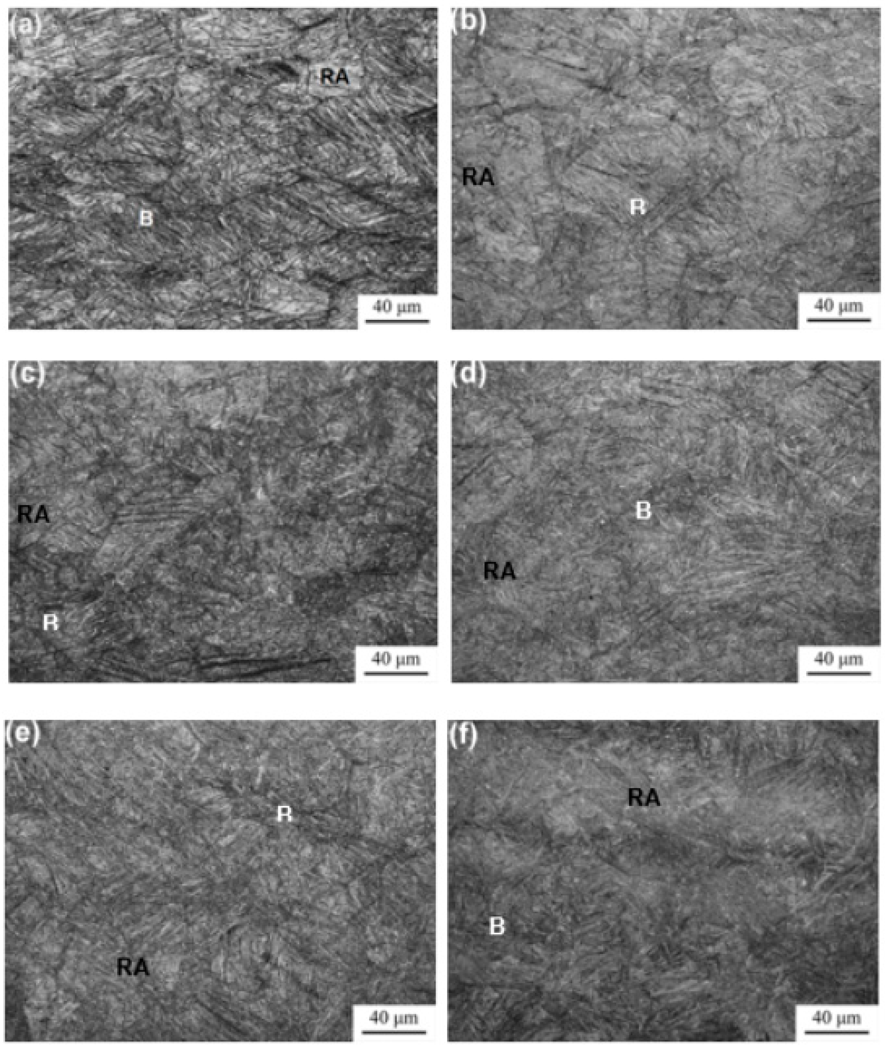
The optical micrographs of the untempered and tempered samples are shown in Figure 1. The black or dark grey needles are bainite. The white blocks are retained austenite. It can be seen that the microstructures of the ausrolled–austempered–tempered samples have no obvious change compared with the ausrolled–austempered samples in Reference [19] (Figure 1a). In addition, the tempered temperature has little effect on the optical micrographs due to the low magnification. Therefore, for further investigation, the microstructures of the samples were examined by TEM.
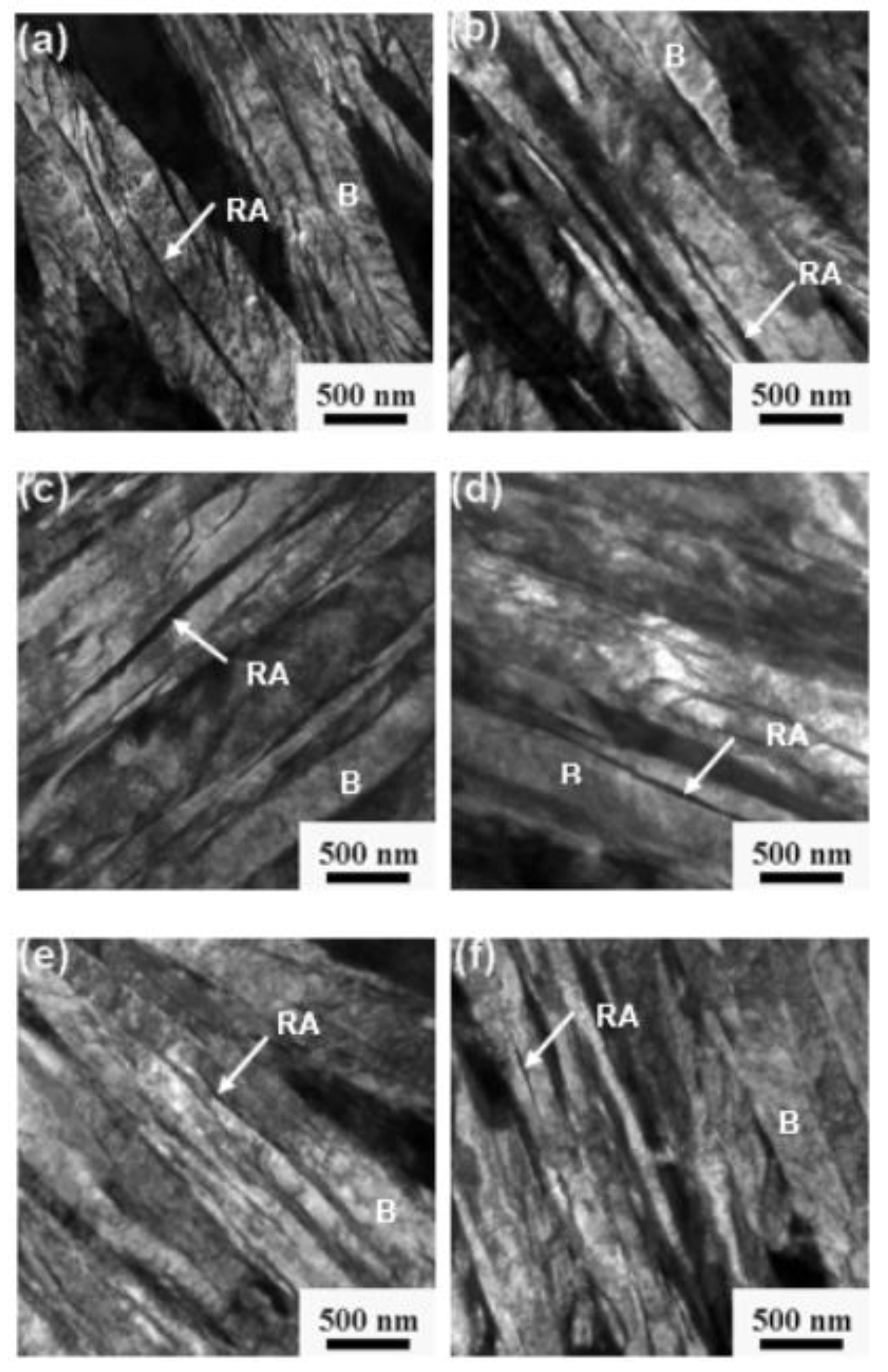
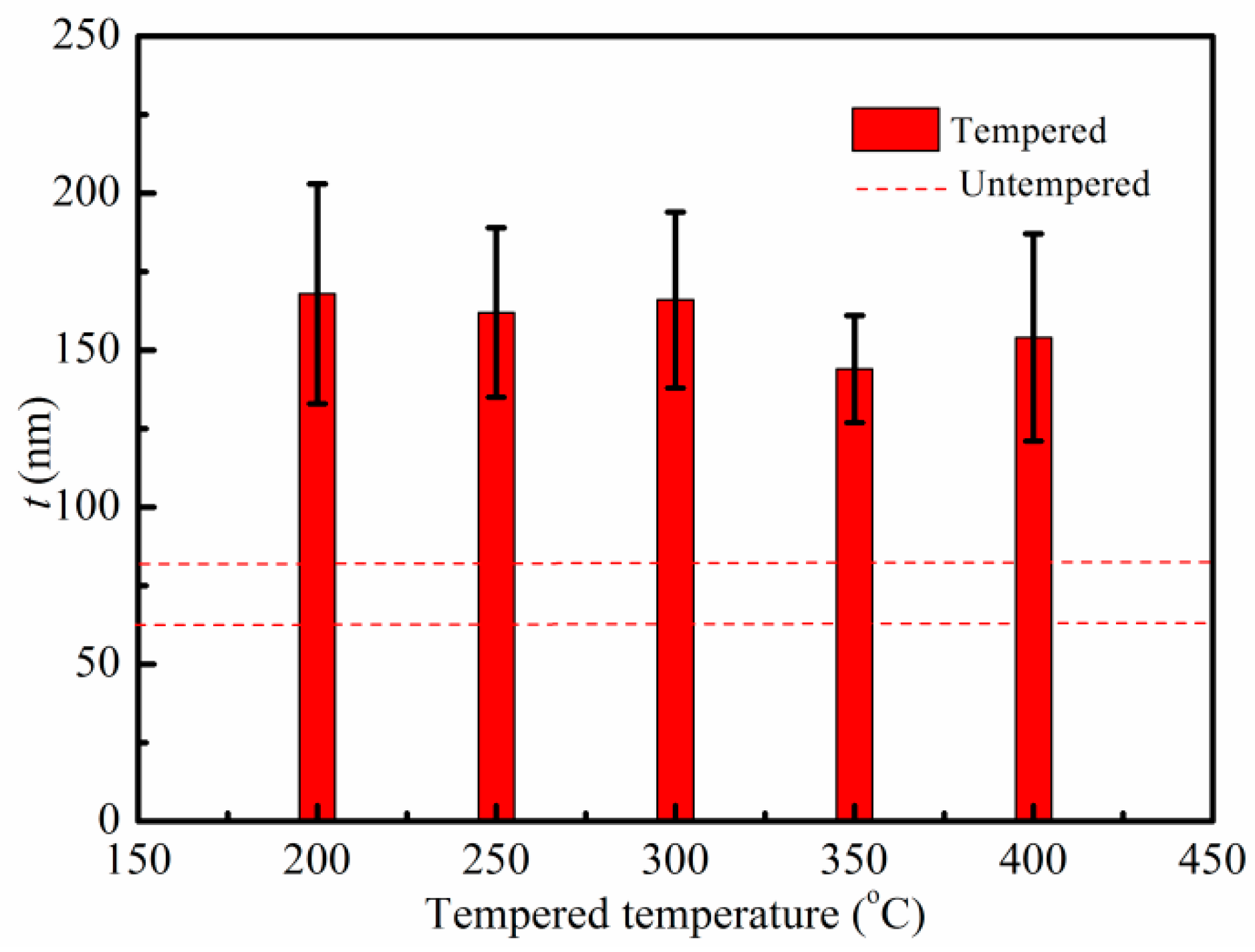
Figure 2 shows typical TEM micrographs of the untempered and tempered samples. The bright laths were bainitic ferrite and the dark laths between the bainite plates were retained austenite. The mean thickness (t) of the laths was stereologically corrected in terms of LT = π t /2 [25]. The mean lineal intercept LT was evaluated by measuring in a direction normal to the lath length. The mean thickness of the bainitic laths for the tempered samples were confirmed to be 144 ± 17 nm to 168 ± 35 nm, as presented in Figure 3. Compared with the untempered samples in Reference [19] (Figure 2a), the bainite ferrite coarsened after tempering.
From Figure 3, it can be seen that when the tempered temperature is at 200–300 °C, there is not much difference in the thickness of bainite ferrite. However, the thicknesses of bainite ferrite are reduced when the tempered temperature reaches 350 °C and 400 °C, the reason for which may be the precipitation of carbides occurring at lath boundaries, which prevents the ferrite from coarsening.
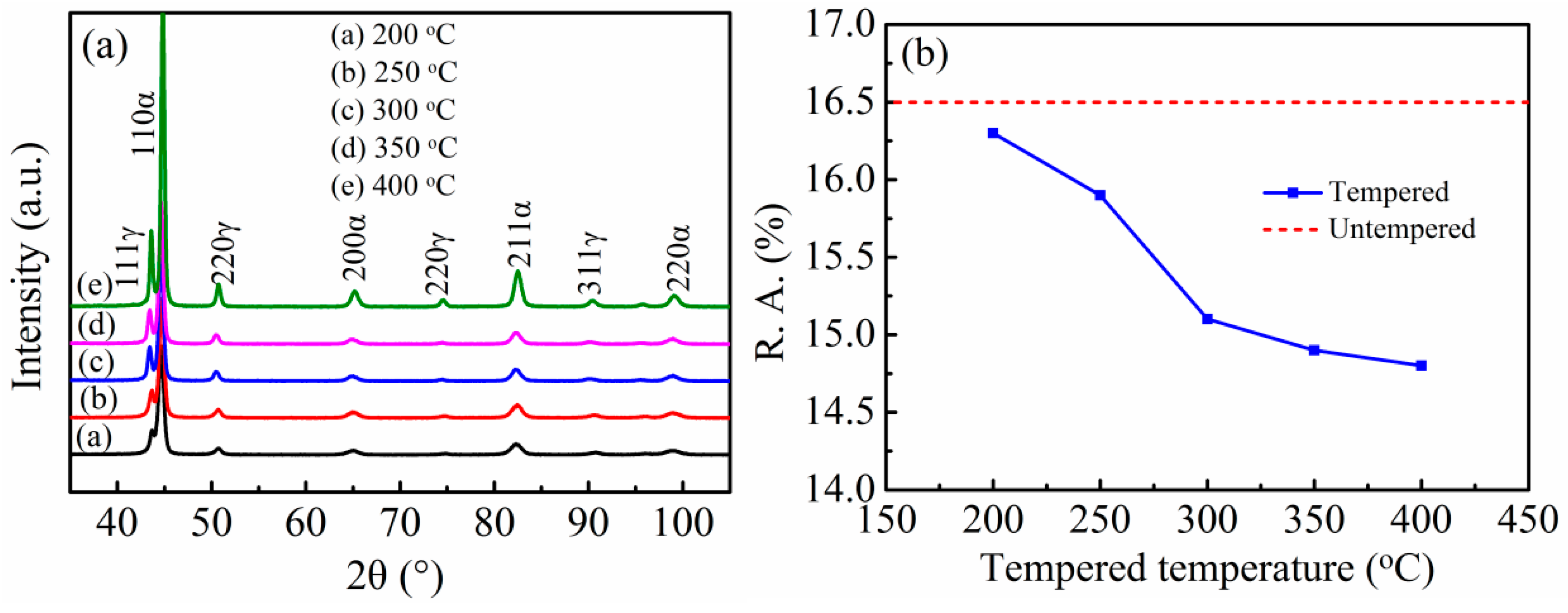
Figure 4 presents the XRD patterns and dependence of retained austenite volume fraction on tempered temperature of tempered samples. In the XRD patterns, the peaks of ferrite (α) and retained austenite (γ) are present. Using a direct comparison method, the volume fractions of the retained austenite were determined by XRD [26]. There were 16.3%, 15.9%, 15.1%, 14.9%, and 14.8% retained austenite in samples tempered at 200–400 °C. The volume fractions of the retained austenite are arranged in order of the elevated tempered temperatures. The volume fractions of the retained austenite slightly decreased with the elevated tempered temperatures.
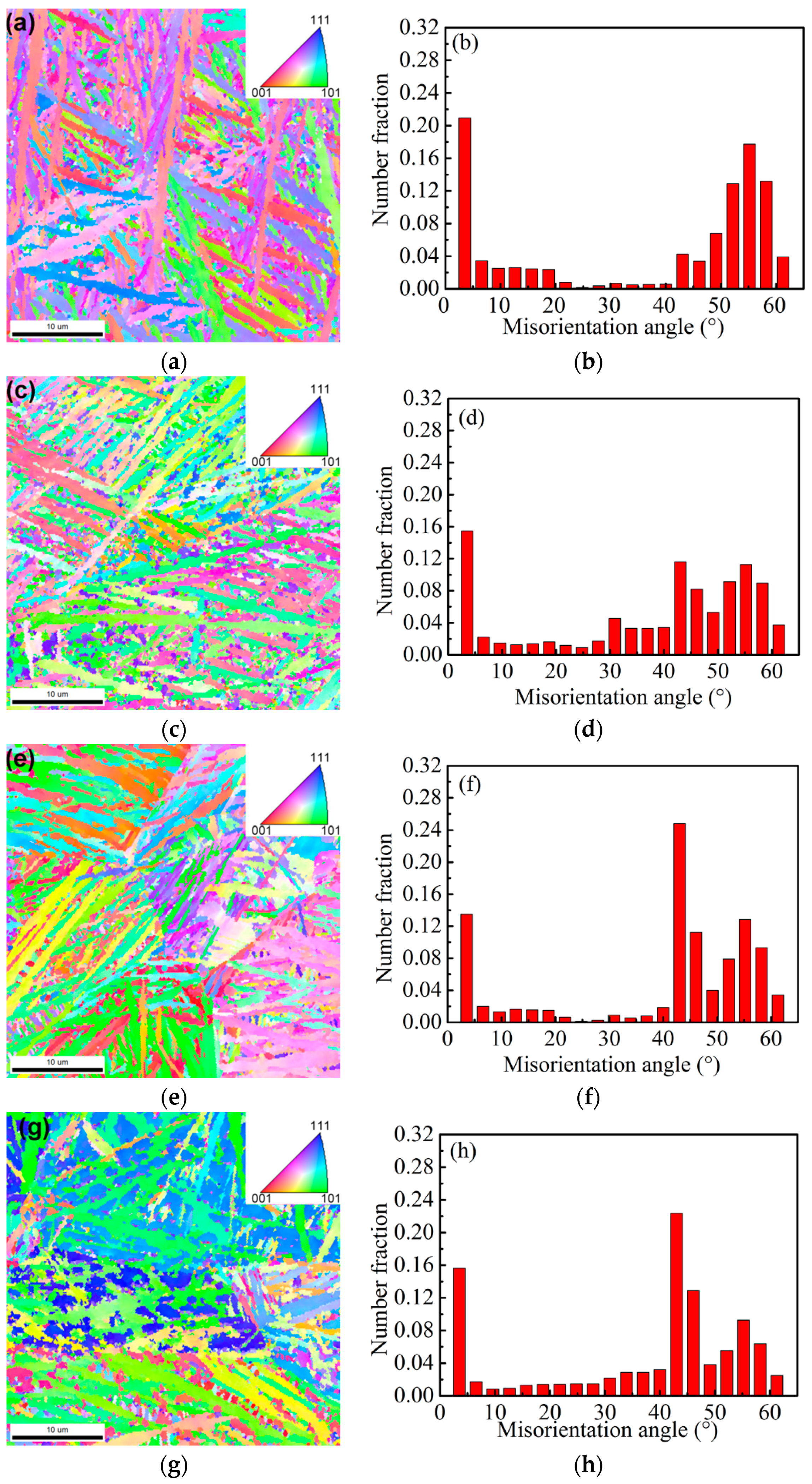
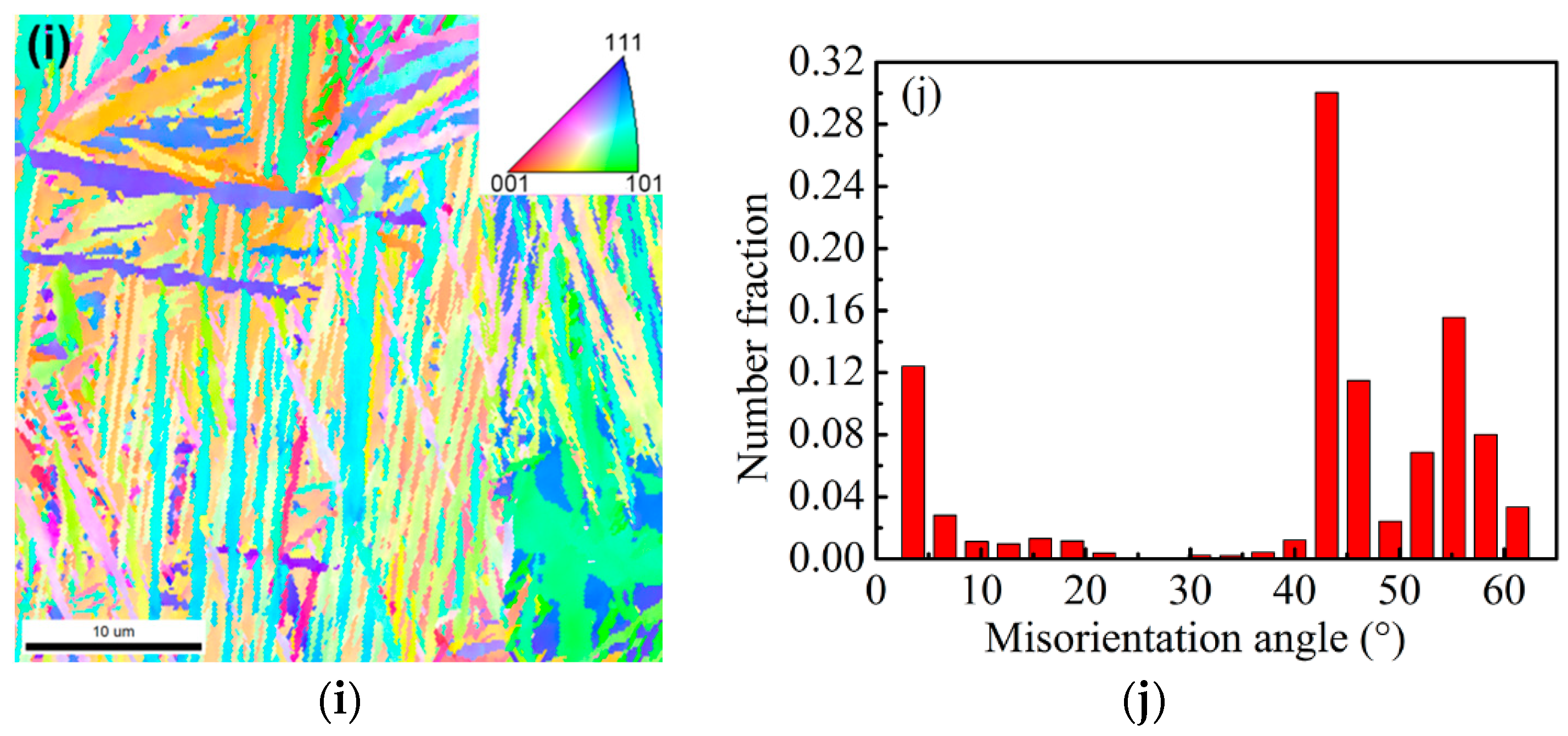
Figure 5 presents the EBSD microstructure characterization of the ausrolled and tempered samples. From Figure 5, it can be seen that the high grain-boundary misorientation angle occupies a great part among the bainitic sheaves and the number fraction of the high grain-boundary misorientation angle increased with elevated tempered temperatures. However, the samples tempered at 200–300 °C show the maximum value of number fraction at 0–5°. When the tempered temperatures reached 300 °C, the number fraction of the low grain-boundary misorientation angle decreased and that of the high grain-boundary misorientation angle increased. The peaks occurred at 43° when the samples were tempered at 300–400 °C.
Kang et al. [18] investigated the EBSD microstructure characterization of samples isothermally transformed at 270 °C and tempered at 240, 320, and 450 °C. The results indicated that the 240 and 320 °C samples exhibited the maximum value of number fraction at 40–50° and 55° misorientation angles. However, when the tempered temperature reached 450 °C, the number fraction of the 55° misorientation angles remained unchanged and the proportion of 40°–50° misorientation angles decreased obviously. The result of this study is different from that of Kang et al. [18], which may be caused by the deformation of supercooled austenite.
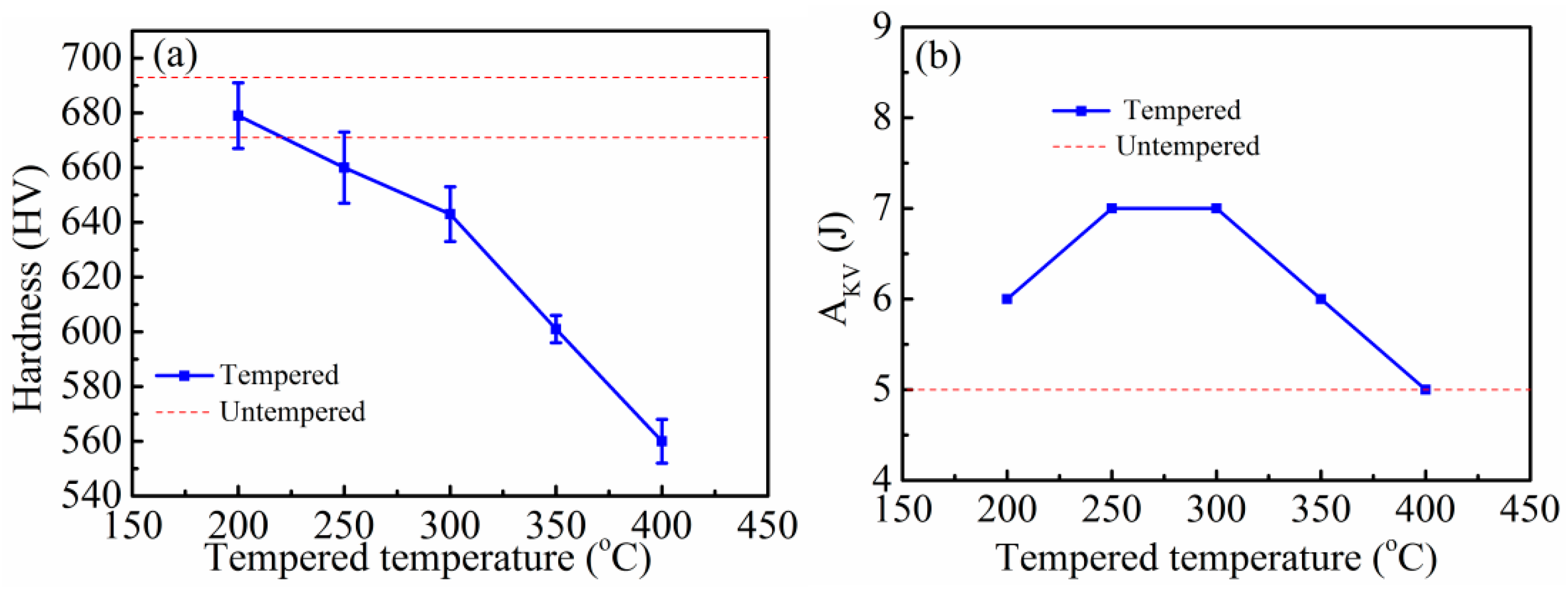
Figure 6 presents the dependence of hardness and impact energy of the samples on tempered temperature. From Figure 6a, it can be seen that the hardness decreased after tempering and with elevated tempered temperature. The hardness decreased slowly during tempering at 200 °C and 300 °C, and then decreased sharply during tempering at 300–400 °C. Figure 6b illuminates the impact of energy increases after tempering, but it is not a monotonous increase. The impact energy increased during tempering at 200 °C and 300 °C, and then decreased during tempering at 300–400 °C.
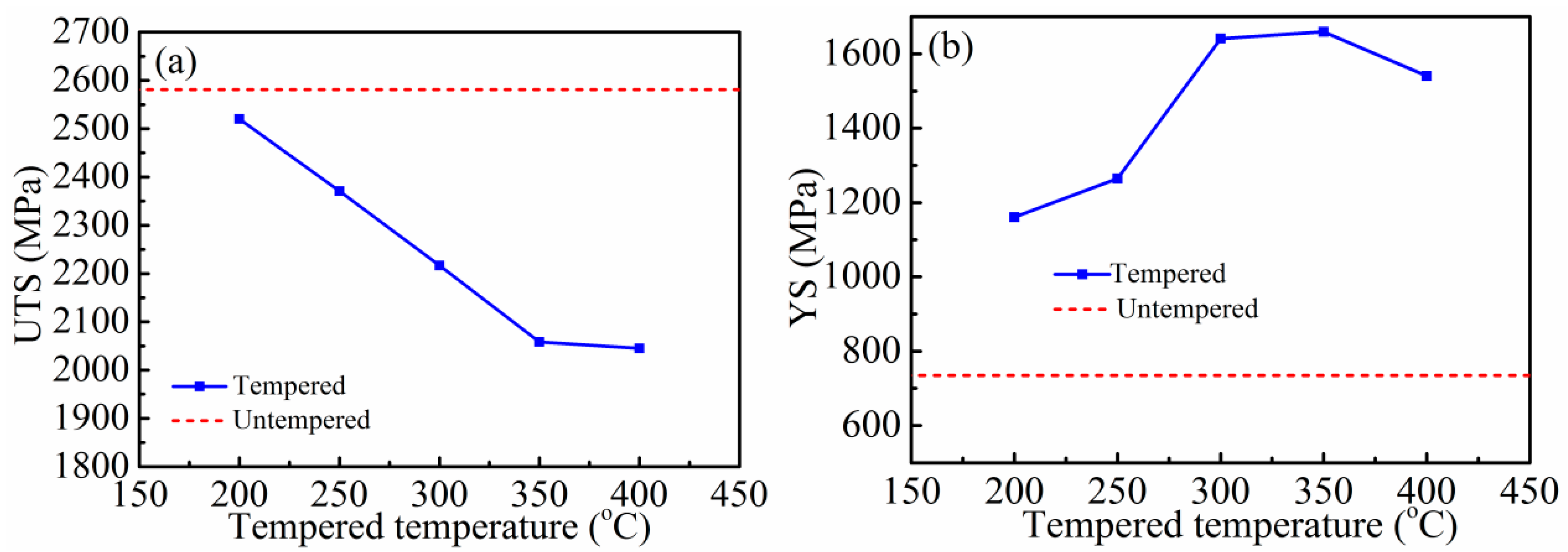
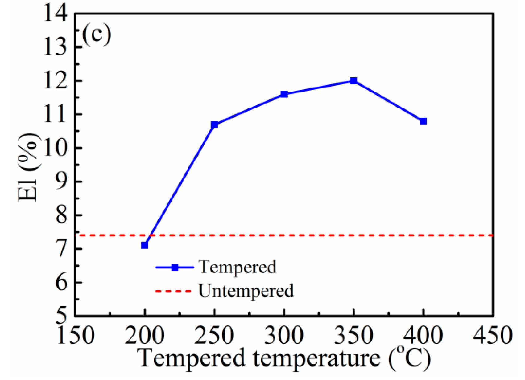
Figure 7 presents the dependence of ultimate tensile strength (UTS), yield strength (YS), and elongation (El) on tempered temperature of the samples. UTS decreased after tempering and with elevated tempered temperature. YS increased after tempering and first increased and then decreased with elevated tempered temperature. El increased after tempering, except for the samples tempered at 200 °C.
Supercooled austenite was reduced by 30% at 500 °C and then quickly immerged in a salt bath and isothermally quenched at a temperature of 200 °C for 15 h. Partial recovery and recrystallization did not occur due to the low temperature. Therefore, the hardness and UTS decreased slightly due to the coarsened bainitic ferrite when the tempered temperature was 200 °C. When the tempered temperature exceeded 200 °C, the microstructure of ausrolled bainite may exhibit partial recovery and recrystallization during the tempering. During the recovery, the dislocation density decreased. Therefore, the hardness and UTS decreased with increasing tempered temperature. The prior austenite grain was refined during recrystallization and YS, El, and impact energy were increased with elevated tempered temperature.
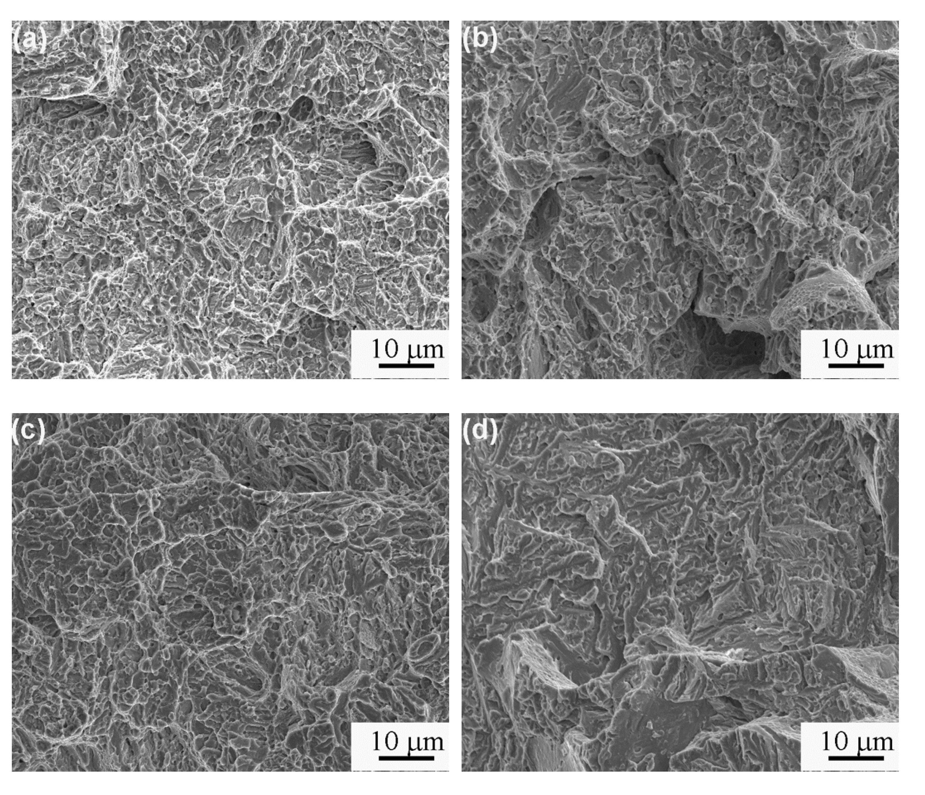
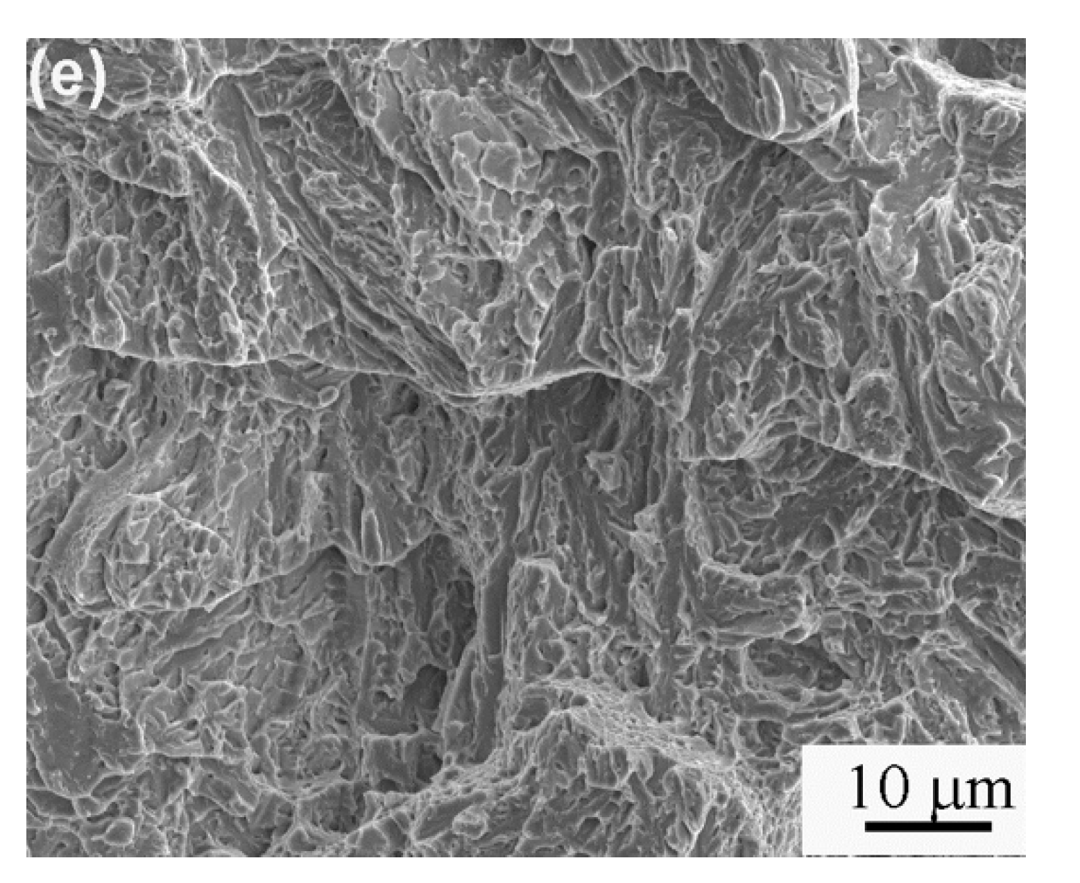
Figure 8 presents the fracture morphologies of samples tempered at different temperatures for 1 h following being isothermally transformed at 200 °C after ausrolling at 500 °C after impact testing. The fracture appearance of all the samples is brittle fracture, and a river pattern was observed in the samples. Almost no tearing ride can be seen in the samples tempered at 200–300 °C, but large quantities of tearing rides are obviously observed in the samples tempered at 350 °C and 400 °C. This phenomenon is in accordance with the difference in impact results.
4. Conclusions
The effect of tempering on microstructures and mechanical properties of ausrolled–austempered samples was investigated. In summary, after tempering, the bainite ferrite coarsened from 70 ± 9 nm to 144 ± 17 nm to 168 ± 35 nm. The volume fraction of retained austenite was reduced, and the impact energy was slightly enhanced. The hardness and UTS decreased sharply. The hardness decreased from 682 ± 11 HV1.0 to 679 ± 12 to 560 ± 8 HV1.0. The UTS decreased from 2581 to 2520−2045 MPa. The YS and El increased, but not monotonously. The impact energy, YS, and El increased with elevated tempered temperature when the samples were tempered at 200–300 °C, but decreased with elevated tempered temperature when they were tempered at 350 °C and 400 °C. When the tempered temperature exceeded 200 °C, the microstructure of ausrolled bainite may have exhibited partial recovery and recrystallization during tempering, so the hardness and UTS decreased, and the YS, El, and impact energy were increased with increasing tempered temperature. The fracture appearance of all the samples after impact testing is brittle fracture.
Author Contributions
Conceptualization, T.W. and D.L.; writing—original draft, J.Z.; methodology, Y.L. and Q.Z.; writing—review and editing, D.L. and Y.Y. All authors have read and agreed to the published version of the manuscript.
Funding
This work was supported by Hubei Superior and Distinctive Discipline Group of "Mechatronics and Automobiles" (No. XKQ2020002), Hubei Key Laboratory of Power System Design and Test for Electrical Vehicle and the National Natural Science Foundation of China (Grant No. 51801051).
Conflicts of Interest
The authors declare no conflict of interest.
References
- Caballer, F.G.; Bhadeshia, H.K.D.H.; Mawella, K.J.A.; Jones, D.G.; Brown, P. Very strong low temperature bainite. Mater. Sci. Technol. 2002, 18, 279–284. [Google Scholar] [CrossRef] [Green Version]
- Garcia-Mateo, C.; Caballero, F.G.; Bhadeshia, H.K.D.H. Development of hard bainite. Isij Int. 2003, 43, 1238–1243. [Google Scholar] [CrossRef] [Green Version]
- Caballero, F.G.; Bhadeshia, H.K.D.H. Very strong bainite. Curr. Opin. Solid State Mater. Sci. 2004, 8, 251–257. [Google Scholar] [CrossRef] [Green Version]
- Caballero, F.G.; Miller, M.K.; Babu, S.S.; Garcia-Mateo, C. Atomic scale observations of bainite transformation in a high carbon high silicon steel. Acta Mater. 2007, 55, 381–390. [Google Scholar] [CrossRef] [Green Version]
- Caballero, F.G.; Miller, M.K.; Garcia-Mateo, C. Carbon supersaturation of ferrite in a nanocrystalline bainitic steel. Acta Mater. 2010, 58, 2338–2343. [Google Scholar] [CrossRef] [Green Version]
- Wang, B.Q.; Song, X.Y.; Peng, H.F. Design of a spheroidization processing for ultrahigh carbon steels containing Al. Mater. Des. 2007, 28, 562–568. [Google Scholar] [CrossRef]
- Zhang, F.C.; Yang, Z.N.; Kang, J. Progress in bainitic steel used for railway crossing. J. Yanshan Univ. 2013, 37, 1–7. [Google Scholar]
- Sswley, K.; Sun, J. Advanced rail steels:investigating the bainitic option. Railw. Track Struct. 1997, 3, 22–27. [Google Scholar]
- Zhang, F.C.; Wang, T.S.; Zhang, P.; Zheng, C.L.; Lv, B.; Zhang, M.; Zheng, Y.Z. Sliding wear and low cycle fatigue properties of new carbide free bainitic rail steel. Scr. Mater. 2008, 59, 294–296. [Google Scholar] [CrossRef]
- Peet, M. Transformation and Tempering of Low-Temperature Bainite; University of Cambridge: Cambridge, UK, 2010. [Google Scholar]
- Bhadeshia, H.K.D.H.; Edmonds, D.V. Bainite in Silicon Steels: New Composition–property Approach Part1. Metal. Sci. 1983, 17, 411–419. [Google Scholar] [CrossRef]
- Bhadeshia, H.K.D.H.; Edmonds, D.V. Bainite in Silicon Steels: New Composition–property Approach Part2. Metal. Sci. 1983, 17, 420–425. [Google Scholar] [CrossRef]
- Sherif, M.Y.; Garcia-Mateo, C.; Sourmail, T.; Bhadeshia HK, D.H. Stablility of retained austenite in trip-assisted steels. Mater. Sci. Technol. 2004, 20, 319–322. [Google Scholar] [CrossRef] [Green Version]
- Sherif, M.Y. Characterisation and Development of Nanostructured, Ultrahigh Strength, and Ductile Bainitic Steels; University of Cambridge: Cambridge, UK, 2005. [Google Scholar]
- Bhadeshia, H.K.D.H. Nanostructured bainite. Proc. R. Soc. A. 2010, 466, 3–18. [Google Scholar] [CrossRef] [Green Version]
- Caballero, F.G.; Miller, M.K.; Garcia-Mateo, C.; Capdevila, C.; Babu, S.S. Redistribution of alloying elements during tempering of a nanocrystalline steel. Acta Mater. 2008, 56, 188–199. [Google Scholar] [CrossRef]
- Hasan, H.S.; Peet, M.J.; Avettand-Fenoel, M.N.; Bhadeshia, H.K.D.H. Effect of tempering upon the tensile properties of nanostructured bainitic steel. Mater. Sci. Eng. A. 2014, 615, 340–347. [Google Scholar] [CrossRef] [Green Version]
- Kang, J.; Zhang, F.C.; Yang, X.W.; Lv, B.; Wu, K.M. Effect of tempering on the microstructure and mechanical properties of a medium carbon bainitic steel. Mater. Sci. Eng. A. 2017, 686, 150–159. [Google Scholar] [CrossRef]
- Zhao, J.; Guo, K.; He, Y.M.; Wang, Y.F.; Wang, T.S. Extremely high strength achievement in medium-c nanobainite steel. Scr. Mater. 2018, 152, 20–23. [Google Scholar] [CrossRef]
- Wang, T.S.; Zhang, M.; Wang, Y.H.; Yang, J.; Zhang, F.C. Martensitic transformation behaviour of deformed supercooled austenite. Scr. Mater. 2013, 68, 162–165. [Google Scholar] [CrossRef]
- Zhang, M.; Wang, Y.H.; Zheng, C.L.; Zhang, F.C.; Wang, T.S. Austenite deformation behavior and the effect of ausforming process on martensite starting temperature and ausformed martensite microstructure in medium-carbon si–al-rich alloy steel. Mater. Sci. Eng. A. 2014, 596, 9–14. [Google Scholar] [CrossRef]
- Zhang, M.; Wang, T.S.; Wang, Y.H.; Yang, J.; Zhang, F.C. Preparation of nanostructured bainite in medium-carbon alloysteel. Mater. Sci. Eng. A. 2013, 568, 123–126. [Google Scholar] [CrossRef]
- Zhang, M.; Wang, Y.H.; Zheng, C.L.; Zhang, F.C.; Wang, T.S. Effects of ausforming on isothermal bainite transformation behaviour and microstructural refinement in medium-carbon si–al-rich alloy steel. Mater. Des. 2014, 62, 158–174. [Google Scholar] [CrossRef]
- Zhao, J.; Jia, X.; Guo, K.; Jia, N.N.; Wang, Y.F.; Wang, Y.H.; Wang, T.S. Transformation behavior and microstructure feature of large strain ausformed low-temperature bainite in a medium C-Si rich alloy steel. Mater. Sci. Eng. A. 2017, 682, 527–534. [Google Scholar] [CrossRef]
- Chang, L.C.; Bhadeshia, H.K.D.H. Austenite Films in Bainitic Microstructures. Mater. Sci. Technol. 1995, 11, 874–881. [Google Scholar] [CrossRef]
- De, A.K.; Murdock, D.C.; Mataya, M.C.; Speer, J.G.; Matlock, D.K. Quantitative Measurement of Deformation-induced Martensite in 304 Stainless Steel by X-ray Diffraction. Scr. Mater. 2004, 50, 1445–1449. [Google Scholar] [CrossRef]
Figure 1.
Optical microscopy (OM) of the samples untempered and tempered at different temperatures for 1 h following being isothermally transformed at 200 °C after ausrolling at 500 °C: (a) untempered; (b) 200 °C; (c) 250 °C; (d) 300 °C; (e) 350 °C; (f) 400 °C.
Figure 1.
Optical microscopy (OM) of the samples untempered and tempered at different temperatures for 1 h following being isothermally transformed at 200 °C after ausrolling at 500 °C: (a) untempered; (b) 200 °C; (c) 250 °C; (d) 300 °C; (e) 350 °C; (f) 400 °C.

Figure 2.
TEM of the samples untempered and tempered at different temperatures for 1 h following being isothermally transformed at 200 °C after ausrolling at 500 °C: (a) untempered; (b) 200 °C; (c) 250 °C; (d) 300 °C; (e) 350 °C; (f) 400 °C.
Figure 2.
TEM of the samples untempered and tempered at different temperatures for 1 h following being isothermally transformed at 200 °C after ausrolling at 500 °C: (a) untempered; (b) 200 °C; (c) 250 °C; (d) 300 °C; (e) 350 °C; (f) 400 °C.

Figure 3.
Bainitic ferrite lath thicknesses of untempered and tempered samples at different temperatures.
Figure 3.
Bainitic ferrite lath thicknesses of untempered and tempered samples at different temperatures.

Figure 4.
XRD patterns and dependence of retained austenite volume fraction on tempered temperature of samples isothermally transformed at 200 °C after ausrolling at 500 °C: (a) XRD patterns and (b) dependence of retained austenite volume fraction on tempered temperature.
Figure 4.
XRD patterns and dependence of retained austenite volume fraction on tempered temperature of samples isothermally transformed at 200 °C after ausrolling at 500 °C: (a) XRD patterns and (b) dependence of retained austenite volume fraction on tempered temperature.

Figure 5.
Electron-backscattered diffraction microscopy (EBSD) microstructure characterization of samples isothermally transformed at 200 °C after ausrolling at 500 °C and tempering at different temperatures: Orientation image (left) and misorientation-angle distribution (right): (a,b) 200 °C; (c,d) 250 °C; (e,f) 300 °C; (g,h) 350 °C; (i,j) 400 °C.


Figure 6.
Dependence of hardness and impact energy on the tempered temperature of samples isothermally transformed at 200 °C after ausrolling at 500 °C: (a) hardness and (b) impact energy.
Figure 6.
Dependence of hardness and impact energy on the tempered temperature of samples isothermally transformed at 200 °C after ausrolling at 500 °C: (a) hardness and (b) impact energy.

Figure 7.
Dependence of ultimate tensile strength (UTS), yield strength (YS), and elongation (El) on tempered temperature of samples isothermally transformed at 200 °C after ausrolling at 500 °C: (a) UTS, (b) YS, and (c) El.
Figure 7.
Dependence of ultimate tensile strength (UTS), yield strength (YS), and elongation (El) on tempered temperature of samples isothermally transformed at 200 °C after ausrolling at 500 °C: (a) UTS, (b) YS, and (c) El.


Figure 8.
Fracture morphologies of samples tempered at different temperatures for 1 h following being isothermally transformed at 200 °C after ausrolling at 500 °C after impact testing: (a) 200 °C; (b) 250 °C; (c) 300 °C; (d) 350 °C; (e) 400 °C.
Figure 8.
Fracture morphologies of samples tempered at different temperatures for 1 h following being isothermally transformed at 200 °C after ausrolling at 500 °C after impact testing: (a) 200 °C; (b) 250 °C; (c) 300 °C; (d) 350 °C; (e) 400 °C.


Table 1.
Chemical composition of the experimental steel (wt.%).
| C | Mn | Si | Ni | Mo | P | S |
|---|---|---|---|---|---|---|
| 0.540 | 1.890 | 1.700 | 1.630 | 0.240 | 0.005 | 0.002 |
© 2020 by the authors. Licensee MDPI, Basel, Switzerland. This article is an open access article distributed under the terms and conditions of the Creative Commons Attribution (CC BY) license (http://creativecommons.org/licenses/by/4.0/).
Share and Cite
MDPI and ACS Style
Zhao, J.; Liu, D.; Li, Y.; Yang, Y.; Wang, T.; Zhou, Q. Microstructure and Mechanical Properties of Tempered Ausrolled Nanobainite Steel. Crystals 2020, 10, 573. https://doi.org/10.3390/cryst10070573
AMA Style
Zhao J, Liu D, Li Y, Yang Y, Wang T, Zhou Q. Microstructure and Mechanical Properties of Tempered Ausrolled Nanobainite Steel. Crystals. 2020; 10(7):573. https://doi.org/10.3390/cryst10070573
Chicago/Turabian StyleZhao, Jing, Dezheng Liu, Yan Li, Yongsheng Yang, Tiansheng Wang, and Qian Zhou. 2020. "Microstructure and Mechanical Properties of Tempered Ausrolled Nanobainite Steel" Crystals 10, no. 7: 573. https://doi.org/10.3390/cryst10070573
Note that from the first issue of 2016, this journal uses article numbers instead of page numbers. See further details here.