Article

Structure Optimization and Failure Mechanism of Metal Nitride Coatings for Enhancing the Sand Erosion Resistance of Aluminum Alloys

1
Science and Technology on Plasma Dynamics Laboratory, Air Force Engineering University, Xi’an 710038, China
2
School of Mechanical Engineering, Xi’an Jiaotong University, Xi’an 710049, China
3
National Key Lab of Aerospace Power System and Plasma Technology, Xi’an Jiaotong University, Xi’an 710049, China
4
China North Engine Research Institute, Tianjin 300400, China
*
Author to whom correspondence should be addressed.
Coatings 2023, 13(12), 2074; https://doi.org/10.3390/coatings13122074
Submission received: 4 November 2023 / Revised: 5 December 2023 / Accepted: 8 December 2023 / Published: 12 December 2023
(This article belongs to the Special Issue Advanced Materials Processing Technology and Surface Engineering)

Abstract

:
In this study, TiN/Ti coatings with various modulation ratios (TiN/Ti-4:1, TiN/Ti-1:1, and TiN/Ti-1:4) were deposited on 2A70 aluminum to improve its sand erosion performance. The structural design of ion implantation + high thickness Ti transition layer + TiN/Ti coatings was applied to alleviate the differences in physical properties between hard nitride coatings and 2A70 aluminum. Surface roughness, XRD, elastic modulus, hardness, and the sand erosion failure mechanism of each coating were evaluated. The hardness of TiN/Ti-4:1, TiN/Ti-1:1, and TiN/Ti-1:4 on aluminum was 26.99 GPa, 21.70 GPa, and 10.99 GPa. Sand erosion test results showed that TiN/Ti-1:1 had the highest erosion rates due to its rougher surface. Under a 90° incident angle, TiN/Ti-4:1 and TiN/Ti-1:4 both exhibited vertical cracks parallel to the coating growth direction in the bottom TiN layer at the initial erosion stage. Also, a lateral crack caused by TiN layer crack deflection emerged due to a higher crack resistance in the thicker Ti layer of TiN/Ti-1:4. Furthermore, in comparison with the layer-by-layer spalling failure behavior of TiN/Ti-1:4, overall spallation induced by the crack coalescence of the TiN layer was exhibited in TiN/Ti-4:1. In addition, cracks formed and intersected in the inner TiN layer in TiN/Ti-1:1 and TiN/Ti-4:1, resulting in layer-by-layer spallation under a 45° incident angle.

1. Introduction

Aluminum alloy turbocharger impellers are crucial power components for tanks and armored vehicles. However, aluminum alloys have low hardness and poor wear resistance. The intake of high-hardness and high-concentration sand in the desert results in reduced impeller service life and shorter engine maintenance intervals, thereby negatively impacting military performance and durability [1,2,3,4,5].
To enhance the service performance of aluminum alloy turbocharger impellers under harsh desert conditions, prolong the equipment’s lifespan, and minimize erosion and wear-induced damage to the aluminum alloy impellers, it becomes imperative to reinforce the surface of the aluminum alloy [1,2,6,7,8,9]. Physical vapor deposition (PVD) of metal nitride coatings, which exhibit high hardness and excellent wear resistance, holds promise in enhancing the erosion resistance of aluminum alloys against sand [10,11,12,13]. The oxidizable nature of aluminum hinders the proper interfacial bonding between aluminum and nitride coatings [7,14,15,16,17]. Youming Liu et al. successfully improved the bonding strength of a TiN/Al system by a factor of six with the ion source injection (MEVVA) of Ti metal particles and Ti intermediate layer pretreatment [18,19,20,21]. Nevertheless, the erosion performance of nitride coatings on aluminum alloy surfaces using this method remains unreported. Additionally, the large disparity in hardness between aluminum alloy substrates and hard nitride coatings, along with differences in lattice constants, hinder the nucleation process and excessive growth stresses [22,23,24,25,26]. Consequently, there is a necessity for a coating structure design that enhances the performance of aluminum alloy surfaces and improves their resistance to sand erosion. Since TiN/Ti coatings exhibit lower internal stress, excellent strength, and toughness compatibility, as well as minimal disparity with aluminum alloys, it is imperative to investigate their erosion resistance and failure mechanism when applied on aluminum alloy surfaces.
In this study, the structural design of ion implantation + Ti transition layer + TiN/Ti coatings was achieved with magnetic filtration vacuum ion plating. The surface morphology and mechanical performance of TiN/Ti coatings at three distinct modulation ratios were evaluated, along with their erosion resistance and failure mechanisms. The aim was to develop erosion-resistant coatings suitable for aluminum alloy materials.

2. Experimental Methods

2.1. Coating Preparation

A magnetic-filtered cathodic vacuum ion plating deposition device with a Ti (99.99 at%) target was used to prepare the anti-erosion coating. Commercially available 2A70 aluminum with the size of 3 mm × 20 mm × 50 mm was used with a chemical composition (in wt.%) of: 0.06 Ti, 1.5 Mg, 0.30 Zn, 0.35 Si, 1.05 Fe, 2.00 Cu, 0.20 Mn, and 1.00 Ni with the remainder consisting of aluminum. After vacuuming the deposition chamber to 1.0 × 10⁻³ Pa, Ti ions were injected into the substrate using a 10 kV bias voltage with a 6 mA ion beam current of 1 h to clean the oxide layer on the aluminum. After that, a Ti metal transition layer was deposited on the specimen surface at −200 V for 2 h. Then, nitrogen gas was inlet into the chamber at 35 sccm to deposit the TiN layer at a bias of −200 V. For the Ti layer, the deposition bias was −200 V. The TiN/Ti modulation ratios were controlled to be 4:1, 1:1, and 1:4 (TiN/Ti-4:1, TiN/Ti-1:1, and TiN/Ti-1:4).

2.2. Structural Characterization and Mechanical Property Testing

The cross-sectional surface morphology of each coating and the coating erosion morphology were observed with field emission scanning electron microscopy (FESEM, FEI Quanta 250). The phase composition was analyzed with an X-ray diffractometer (D8-Advance, Bruker, Germany). For the phase composition, the measurement angles ranged from 20 to 90°, and the scanning speed was 10 °/min. The elastic modulus and hardness of the TiN/Ti coating were measured using nanoindentation with the instrument model TI950. The indenter of the nanoindentation instrument was a Berkovich-shaped diamond indenter. Each sample was tested at five points to obtain the average value. The surface roughness of the deposited coatings was measured using a laser confocal microscope. In addition, the adhesive force between the substrate and the coating was measured using a WS-2005 scratch tester fitted with a Rockwell C diamond indenter. The maximum loading force, scratch length, and loading speed were set at 100 N, 5 mm, and 100 N·min−1. The elemental composition of each coating was analyzed using an energy-dispersive X-ray spectroscopy (EDS) system.
The sand erosion test equipment was designed based on ASTM-G76 [15,27,28,29]. The erosion speed, sand type, and sand supply were set to 135 m·s−1, 0–75 μm SiO2, and 2.3 g·min−1. The incident angle was set to 90° and 45°. The erosion time was set to 60 s, 120 s, 180 s, 240 s, and 300 s. The mass of the specimen before and after erosion was weighed using an electronic analytical balance. The mass of the specimen was weighed 3 times after each erosion, and the results were averaged. The data points at each erosion time were selected to draw the curve of the relationship between the mass loss and the amount of sand supply. Subsequently, the data points were analyzed with least squares data fitting, and the slope after fitting was the erosion rate.

3. Results and Discussion

3.1. Coating Surface Morphology and Microstructure

Figure 1 shows the coating surface of the TiN/Ti coatings (TiN/Ti-4:1, TiN/Ti-1:1, and TiN/Ti-1:4) after deposition. It shows that when the TiN/Ti modulation ratio is 1:1, the spallation of the coating is obvious, showing rough and non-uniform holes. Metal droplets are observed on the coating surface. These droplet protrusions can easily become a concentrated site of erosion or fatigue or lead to a coating that is more susceptible to cracks and spalling. Figure 2 shows the roughness of the prepared TiN/Ti coatings. The TiN/Ti-1:1 has the largest roughness value, and the coating surface quality is the worst. The surface roughness value of TiN/Ti-4:1 and TiN/Ti-1:4 is similar. The surface roughness results are the same as the surface morphology of the TiN/Ti coatings shown in Figure 1.
Figure 3 shows the cross-sectional morphologies of the prepared TiN/Ti coatings. The coating structure was observed using backscattered electrons (BSEs) [30,31]. The total thickness of each coating is between 9 and 12 μm, as shown in Figure 3. The multilayer coating structure is identifiable using its contrast, with the Ti layer appearing light and the TiN layer appearing dark. The thickness of the TiN ceramic layer decreases with the modulation ratio in the order of 1.49 μm, 1.18 μm, and 0.31 μm. While the Ti layer thickness is 0.37 μm, 1.09 μm, and 1.26 μm, respectively. The thickness ratios are close to 4:1, 1:1, and 1:4. In addition, the thickness of the Ti transition layer of each coating is about 2.0 μm. A thick Ti transition layer can effectively alleviate the differences in physical properties between hard coatings and 2A70 aluminum alloy substrates.
Figure 4 exhibits the X-ray diffraction profile of three coatings. It demonstrates the presence of both Ti and TiN phases in all three modulation ratios, which suggests that the multilayer coatings consist of a combination of metallic titanium and titanium nitride. The concentration of Ti and TiN phases varied with the modulation ratio. For TiN/Ti-1:1, the peaks corresponding to both Ti and TiN phases exhibited the highest concentration. On the contrary, a significant rise in the content of the TiN phase was observed at TiN/Ti-4:1. This suggests that a higher proportion of titanium nitride was incorporated into the coating structure, potentially leading to altered mechanical and chemical properties. Conversely, in the case of TiN/Ti-1:4, the Ti phase exhibited a more prominent presence. This finding indicates that a higher concentration of metallic titanium was present within the coating structure at this modulation ratio. Table 1 shows the chemical composition of Ti and N elements in the TiN/Ti coatings with different modulation ratios. From the table, it can be seen that the content of the Ti element in the prepared TiN/Ti coating is slightly higher than that of the N element. This means that in the prepared TiN/Ti coating, TiN was a non-stoichiometric TiNx.

3.2. Mechanical Properties

Figure 5a presents the elastic modulus and hardness of the TiN/Ti coatings at different modulation ratios. The hardness values of TiN/Ti-4:1, TiN/Ti-1:1, and TiN/Ti-1:4 are 26.99 GPa, 21.70 GPa, and 10.99 GPa, and the elastic modulus values were 250.87 GPa, 209.94 GPa, 136.27 GPa. Both the hardness and elastic modulus exhibit a significant decrease as the TiN phase gradually decreases. The peak values of the hardness and elastic modulus are reached for TiN/Ti-4:1 and decrease significantly after the addition of the Ti metal transition layer. The fracture toughness of erosion-resistant coatings can be characterized by the H3/E2 value, which indicates the resistance to plastic deformation [32]. Coatings with larger H3/E2 values have higher toughness.
Figure 5b shows the H3/E2 values of the TiN/Ti coatings at three distinct modulation ratios. Th H3/E2 shows a monotonically decreasing trend with the increase in the Ti layer thickness in each coating. The higher the TiN content, the higher of elastic modulus and hardness, indicating a better ability of the material to resist plastic deformation. When the modulation ratios are 4:1 and 1:1, the hardness, elastic modulus, and H3/E2 values do not differ significantly. However, when the modulation ratio is changed to 1:4, there is a significant change in these mechanical properties. When the TiN/Ti multilayer coatings are applied to titanium alloys, the hardness value is up to 28.65 GPa, with an H3/E2 value of 0.257. The hardness of the designed TiN/Ti coating structure deposited on aluminum does not change significantly.
The adhesion force between the TiN/Ti coatings and the substrate were analyzed using a scratch tester. The scratch test results of the TiN/Ti-1:1 coating are shown in Figure 6a. When the applied force is below 30 N, the coating surface remains intact without any signs of cracking. However, upon reaching a loading force of 30 N, surface cracks become evident, aligning with the cohesive force of the coating. Subsequently, as the loading force escalates to 45 N, a progressive rise in sound signals is observed. The examination of scanning electron microscopy results indicates a discernible separation between the coating and the substrate. The adhesion force of the TiN/Ti coatings with different modulation ratios are shown in Figure 6b. The adhesion force of TiN/Ti-4:1, TiN/Ti-1:1, and TiN/Ti-1:4 are 32.9 N, 42.1 N, and 45.8 N.

3.3. Sand Erosion Performance

Figure 7 shows the erosion mass loss with the sand supply for the TiN/Ti multilayer coatings and aluminum alloy. The mass loss has an overall linear relationship with the amount of sand supplied. With an increase in the sand supply, the coating mass loss shows an increasing trend. Furthermore, there are still slight differences between each coating at different erosion stages. In Figure 7a, for TiN/Ti-4:1, two different mass loss stages can be observed before and after the 6.9 g sand supply. When the sand supply falls below 6.9 g, in stage I, marked by a red dashed circle in Figure 7a, the local slope surpasses the overall slope, resulting in an increased erosion rate and more severe mass loss. In the range of 6.9 g to 11.5 g of sand supply in stage II, marked by a yellow dash circle in Figure 7b, the local slope of mass loss is diminished, resulting in a decreasing erosion rate.
Comparing Figure 7a,c for TiN/Ti-1:4 and the amount of sand supplied less than 4.6 g, in stage I, marked by a yellow dashed circle in Figure 7c, the local slope has a smaller value relative to the overall slope. This means that the erosion rate is lower and the amount of quality loss is smaller. When the amount of sand supplied is in the range of 4.6–11.5 g, in stage II, marked by a red dash circle in Figure 7c, the local slope is significantly larger than the overall slope. This means that the erosion rate is higher, and the quality loss is more serious. In Figure 7b, the slope value for TiN/Ti-1:1 fluctuates less from the beginning to the end of erosion. That is, there is no obvious gap between the overall slope and the localized slope. The fluctuation in the slope values is also small for the aluminum alloy substrate in Figure 7d.
Figure 8 shows the TiN/Ti coating erosion rate obtained using the least-squares fitting method. The erosion rates of TiN/Ti at 4:1, 1:1, 1:4 and 2A70 aluminum were 0.03 mg·g−1, 0.09 mg·g−1, 0.05 mg·g−1, and 1.27 mg·g−1. The erosion resistance of 2A70 aluminum was significantly improved with the TiN/Ti coating. The ability of the TiN/Ti coatings to significantly enhance the erosion performance of aluminum alloy substrates is demonstrated by the findings presented in this study. For multilayer coatings, in addition to the TiN/Ti modulation ratio, the number of coating layers affects the erosion performance of the deposited coating. Cao et al. reported that the erosion rate of a coating is measured at 0.1 mg·g−1 when the number of layers is two. However, the erosion rate significantly decreases to 0.085 mg·g−1 when the number of layers rises to four [33]. The erosion rate starts to increase again beyond this optimal number of layers, indicating a deterioration in the erosion resistance. This demonstrates that the optimum erosion resistance is achieved with a coating consisting of four layers. Figure 9 shows the typical eroded surface of a TiN/Ti coating. The coating spallation phenomenon as well as a circumferential crack was observed.
To investigate the failure mechanism of TiN/Ti coatings under sand erosion, as well as to explore the reasons for the difference between the localized and overall erosion rates when the modulation ratios of the TiN/Ti multilayer coatings are 4:1 and 1:4, the eroded surfaces were wire-cut. Crack details in the coating cross-section after polishing were observed from the cut surface using SEM. As the erosion time of the specimens varied, the specimens showed a large number of erosion points and cracks due to the 90° angle of the punch and the impact of the specimens with vertical particles, which eventually led to failure.
Figure 10 demonstrates the failure process for a TiN/Ti modulation ratio of 1:4 at an erosion angle of 90° when the sand dust feed is gradually increased. Figure 10a–c shows the erosion damage for the sand supply of 2.3 g, 4.6 g, and 11.5 g. It demonstrates that vertical cracks, i.e., cracks along the coating growth direction, appeared in several TiN coatings when the sand supply was low. Furthermore, the TiN coatings at the bottom show a high number of vertical cracks with deeper cracks, i.e., the bottom TiN layer in the figure, while the TiN coating away from the substrate has fewer vertical cracks and shallower cracks. This indicates that the vertical cracks spread from close to the substrate from the bottom up to multiple TiN layers and began to expand gradually. However, since the Ti layer is more difficult to pass through as a toughness layer, it increases the resistance to cracks, and thus, only the propagation of vertical cracks between TiN layers occurs. At the same time, deeper vertical cracks also appeared at the combination of the substrate and the Ti layer, and no lateral cracks appeared. Figure 10b demonstrates that with the gradual increase in the amount of sand supplied, lateral cracks began to appear at the interface of the TiN ceramic coating and the Ti layer, i.e., cracks normal to the coating growth direction. The horizontal cracks extend laterally and widen inward within the Ti coating. Meanwhile, the vertical cracks deepen in the degree of expansion compared with Figure 10a. Due to the successive impacts of the sand, the TiN/Ti multilayered coatings show three major features: (1) vertical cracks on the TiN coatings spanning across the Ti layer from close to the substrate; (2) vertical cracks on the TiN coating extend from near the substrate across the Ti layer; and (3) lateral cracks in the TiN coating extend toward the Ti layer, and the lateral cracks are deeper. Ti, as a ductile layer, is relatively thick and thus has a high resistance to crack extension, which is manifested by the use of layer-by-layer spalling. As shown in Figure 10c, when the amount of sand supplied is further increased, the lateral cracks also extend. Once the vertical crack expands to cross the lateral crack, it will cause a wide range of failures and eventually lead to the spalling phenomenon.
Figure 11 demonstrates the failure process of TiN/Ti-4:1 at an erosion angle of 90° when the sand supply is 2.3 g, 4.6 g, 6.9 g, and 11.5 g. Figure 11a shows that vertical cracks appeared at the TiN coating nearest to the substrate at a lower sand supply. Figure 11b shows that as the sand supply rises, the crack number and width increase. Crack deflection along the interface of the Ti and TiN layers is observed. Figure 11c shows more vertical crack deflection in TiN. Since the Ti layer thickness is not as thick as that of the multilayer coating with a modulation ratio of 1:4, the cracks in the TiN layer could pass through the Ti layer. Also, the lateral cracks have a tendency to expand horizontally. In Figure 11d, the coating shows overall spalling. A larger number of densely distributed vertical cracks, vertical cracks, progressively expanding lateral cracks, and cracks deflected horizontally occurred on all TiN layers, which together led to bulk spalling.
Figure 12a shows the erosion rates of the TiN/Ti-4:1, TiN/Ti-1:1, and TiN/Ti-1:4 coatings at an erosion angle of 45°.The erosion rates of the TiN/Ti-4:1, TiN/Ti-1:1, and TiN/Ti-1:4 coatings are 0.01 mg·g−1, 0.03 mg·g−1, and 0.02 mg·g−1, respectively. The surface morphology of the TiN/Ti-1:1 coating after erosion is shown in Figure 12b,c. The morphology of the TiN/Ti coating with a 90° erosion angle is a circular shape. However, the erosion pits of the TiN/Ti coating with a 45° erosion angle are elliptical, with a large amount of surface detachment.
Figure 13 shows the cross-sectional morphology evolution of the TiN/Ti-1:1 coating with the gradual increase in sand input at 45°. When the sand input was 2.3 g, as shown in Figure 13a, cracks parallel to the direction of sand erosion appeared in the TiN layer. Meanwhile, the crack gradually propagated along the TiN layer and terminated at the interface between the TiN and Ti layers. As the sand input increased to 4.6 g, shown in Figure 13b, the outermost TiN layer peeled off, and multiple cracks parallel to the erosion direction merged in the inner TiN sublayer. With the further increase of sand input, the total number of TiN/Ti coating layers decreased, and a massive coating spallation phenomenon was observed.
To compare the failure process of TiN/Ti coatings with different modulation ratios at a 45° erosion angle, TiN/Ti-4:1 was selected for analysis. Figure 14 shows the cross-sectional morphology of the TiN/Ti-4:1 coating at different sand inputs. When the sand input was 2.3 g, as shown in Figure 14a, the TiN/Ti-4:1 coating maintained its intact morphology, except for cracks parallel to the erosion angle appearing in the internal TiN layer. As the sand input increased to 4.6 g, shown in Figure 14b, the outermost TiN layer peeled off, and cracks in the TiN layer propagated across layers. With the further increase in sand input, crack intersection as well as massive coating spallation was observed.
A comparison of Figure 10a and Figure 11a clearly shows that for the TiN/Ti coatings, the initial failure of TiN/Ti-4:1 is more serious, and lateral cracks appear earlier. However, along with the gradual increase in the sand supply, the coating with a modulation ratio of 1:4 appears earlier with single-layer spalling and cross phenomena between lateral cracks and vertical cracks. For the multilayer coatings with a modulation ratio of 4:1, some of the vertical cracks first appear to be deflected in the horizontal direction. And because of the lower value of Ti layer thickness, the cracks tend to run through multiple coatings and overall spalling occurs. The hardness and modulus of elasticity values are lower when the TiN/Ti coating modulation ratio is 1:4, and the erosion process is a cumulative fatigue damage process Therefore, under the same sand supply, the resistance to sand dust is worse than that of TiN/Ti-4:1.
The same TiN/Ti multilayer coating, when acting on titanium alloys subjected to the erosive action of sand, reflects a large difference in the failure mechanism [34,35]. As the amount of sand supply increases, the coating first forms vertical cracks in the top TiN layer attributed to the impact of sand particles. Then, it expands downward inside the TiN layer, and cracks initiated at the top TiN layer pass through TiN/Ti to form penetration cracks. When the penetration crack extends downward, it is obstructed by the interface, and the crack extension terminates. Crack deflection occurs at the TiN-Ti interface. The main reason for this is that the plastic deformation in Ti consumes part of the impact energy in the multilayer TiN/Ti coating. Also, the multilayer interface inhibits crack extension in the coating, so deflection often occurs. However, when the substrate is an aluminum alloy, cracks expand on several TiN layers at the same time because titanium alloys have higher strength and hardness relative to aluminum alloys [4,8,14].

4. Conclusions

In this study, the erosion failure behavior of TiN/Ti multilayer coatings on 2A70 aluminum with different modulation ratios was investigated using air blast erosion experiments. The main conclusions are as follows:
(1)
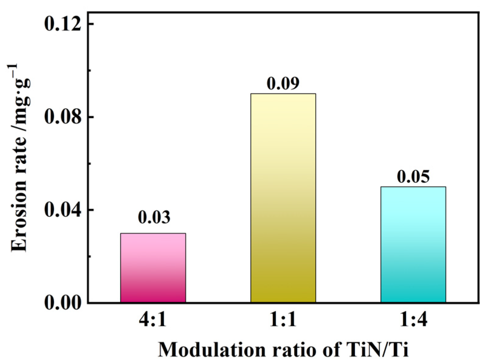
The TiN/Ti multilayer coatings, compared with the aluminum alloy substrate, exhibited significantly improved erosion performance. The erosion rate of the aluminum alloy substrate was 14–42 times higher than the TiN/Ti coating.
(2)
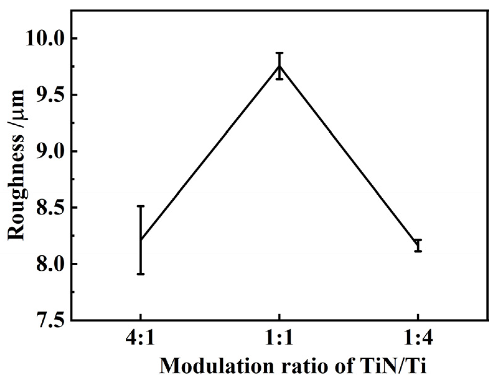
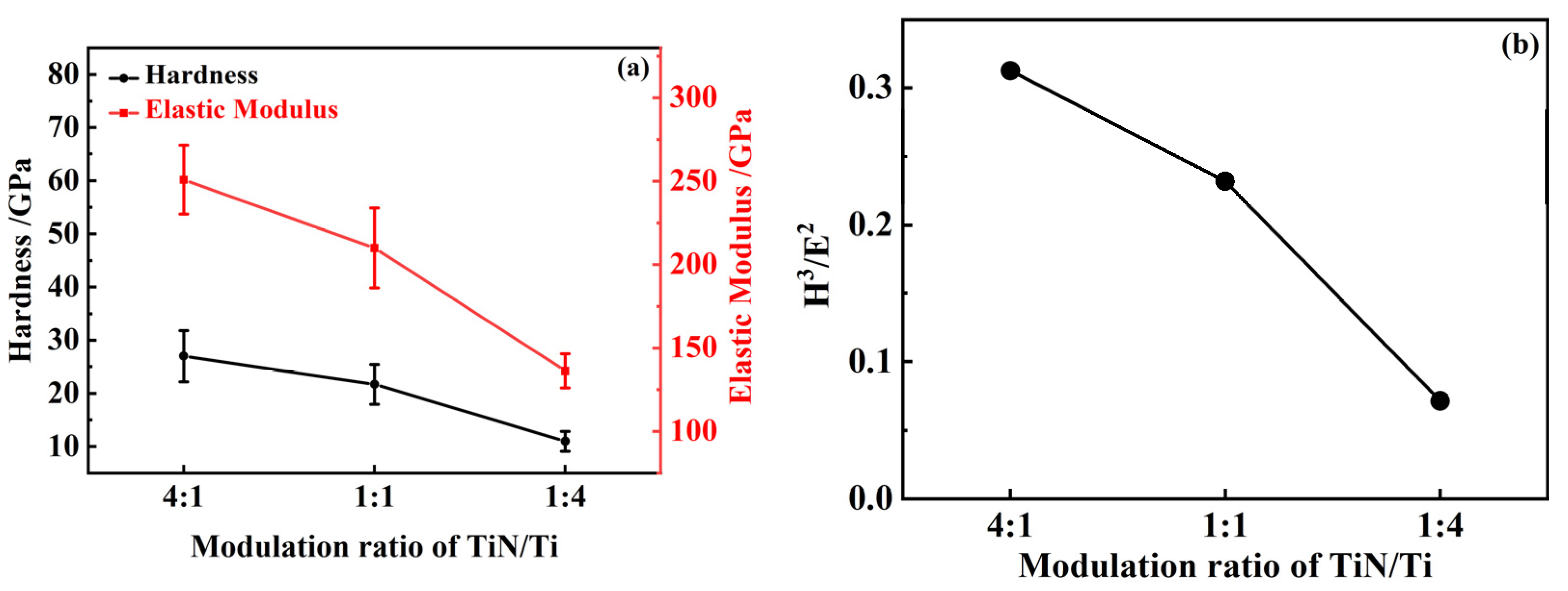
The roughness values were 8.21 μm, 9.75 μm, and 8.16 μm, respectively. The TiN/Ti coatings with a modulation ratio of 1:1 had the largest roughness value and the poorest surface quality. The hardness values of the TiN/Ti-4:1, TiN/Ti-1:1, and TiN/Ti-1:4 multilayer coatings were 26.99 GPa, 21.70 GPa, and 10.99 GPa, respectively, and the elastic modulus values were 250.87 GPa, 209.94 GPa, 136.27 GPa.
(3)
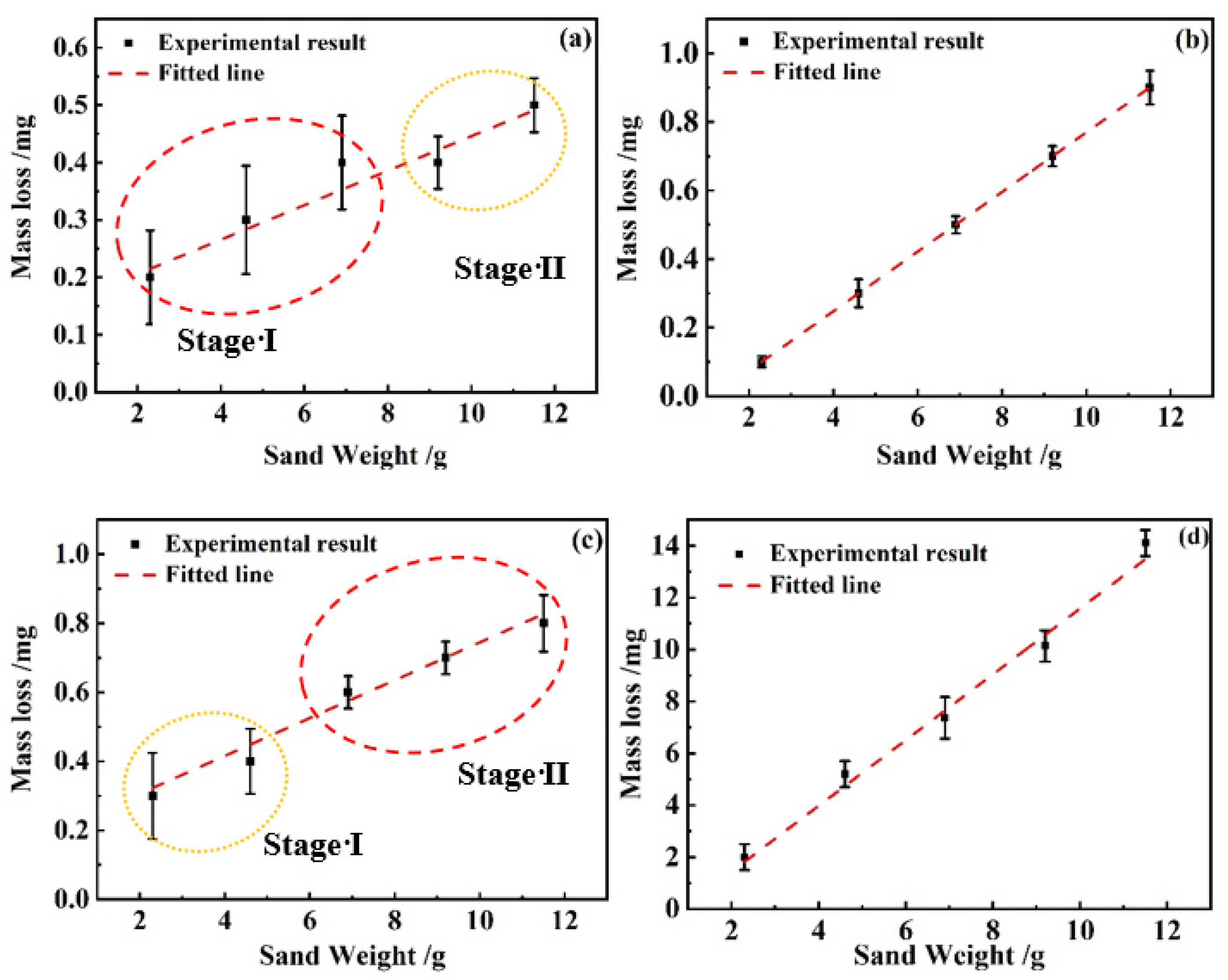
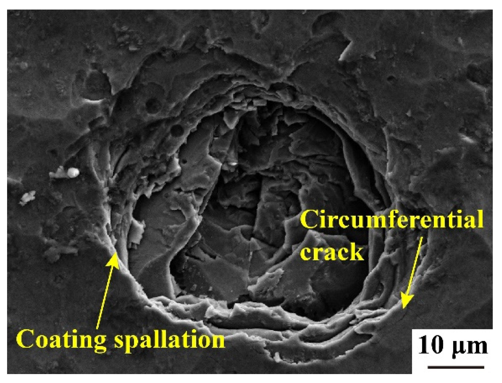
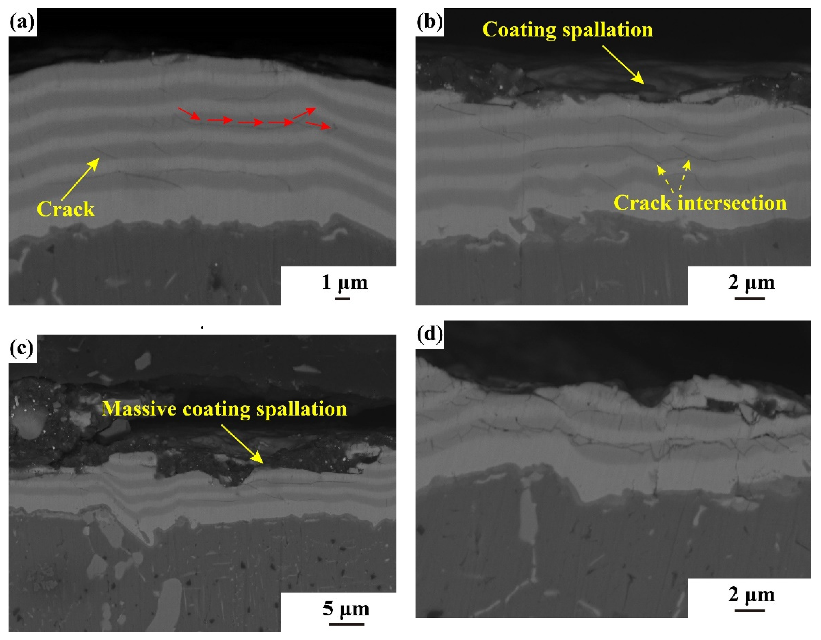
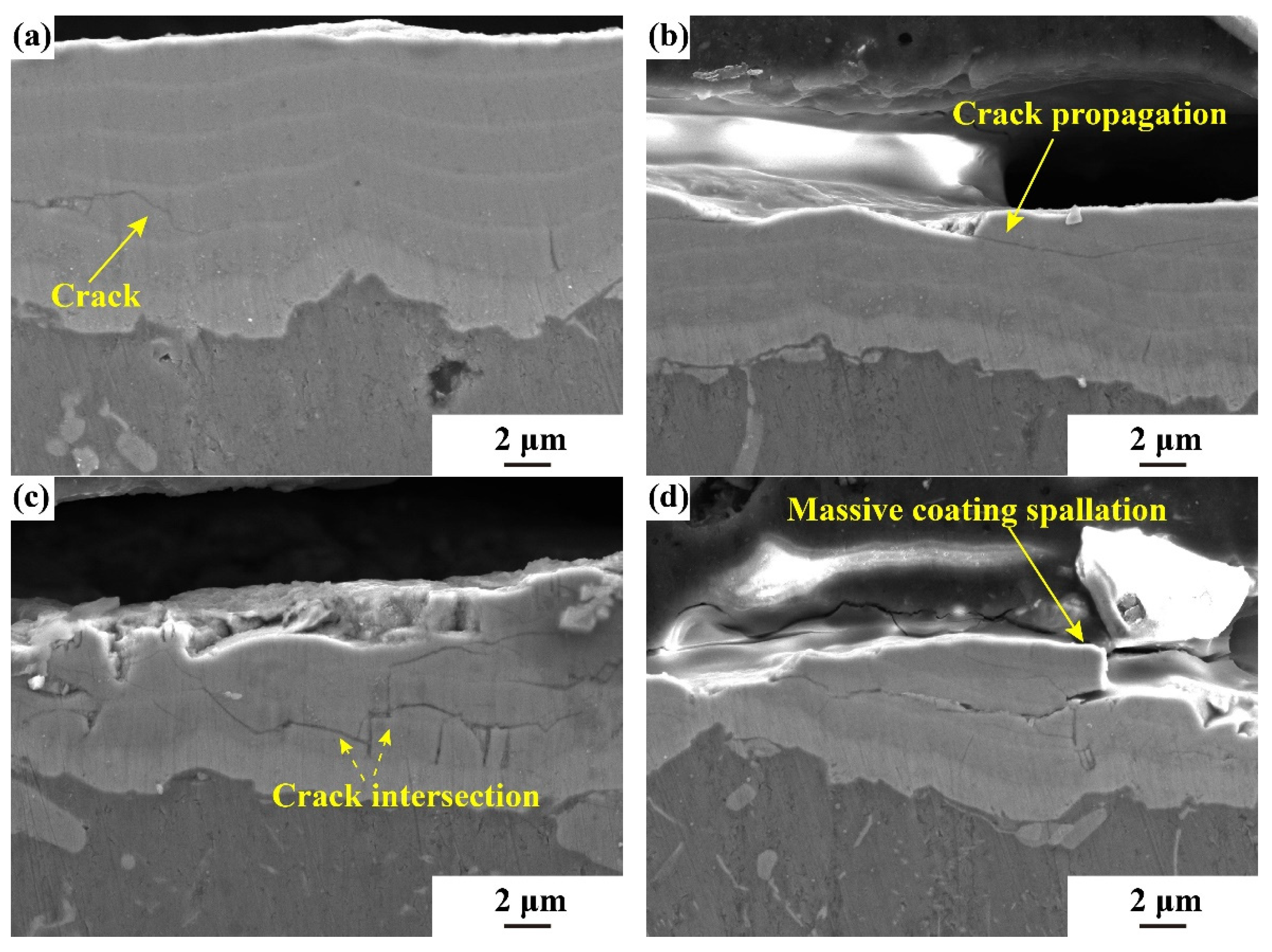
The erosion performance of the TiN/Ti-4:1, TiN/Ti-1:1, and TiN/Ti-1:4 coatings under 45° and 90° were compared. The coating with a 1:1 ratio showed the highest mass loss and poorest erosion resistance due to its rougher surface and lower quality. Both TiN/Ti-4:1 and TiN/Ti-1:4 exhibited crack initiation, extension, and exfoliation as failure stages.
(4)
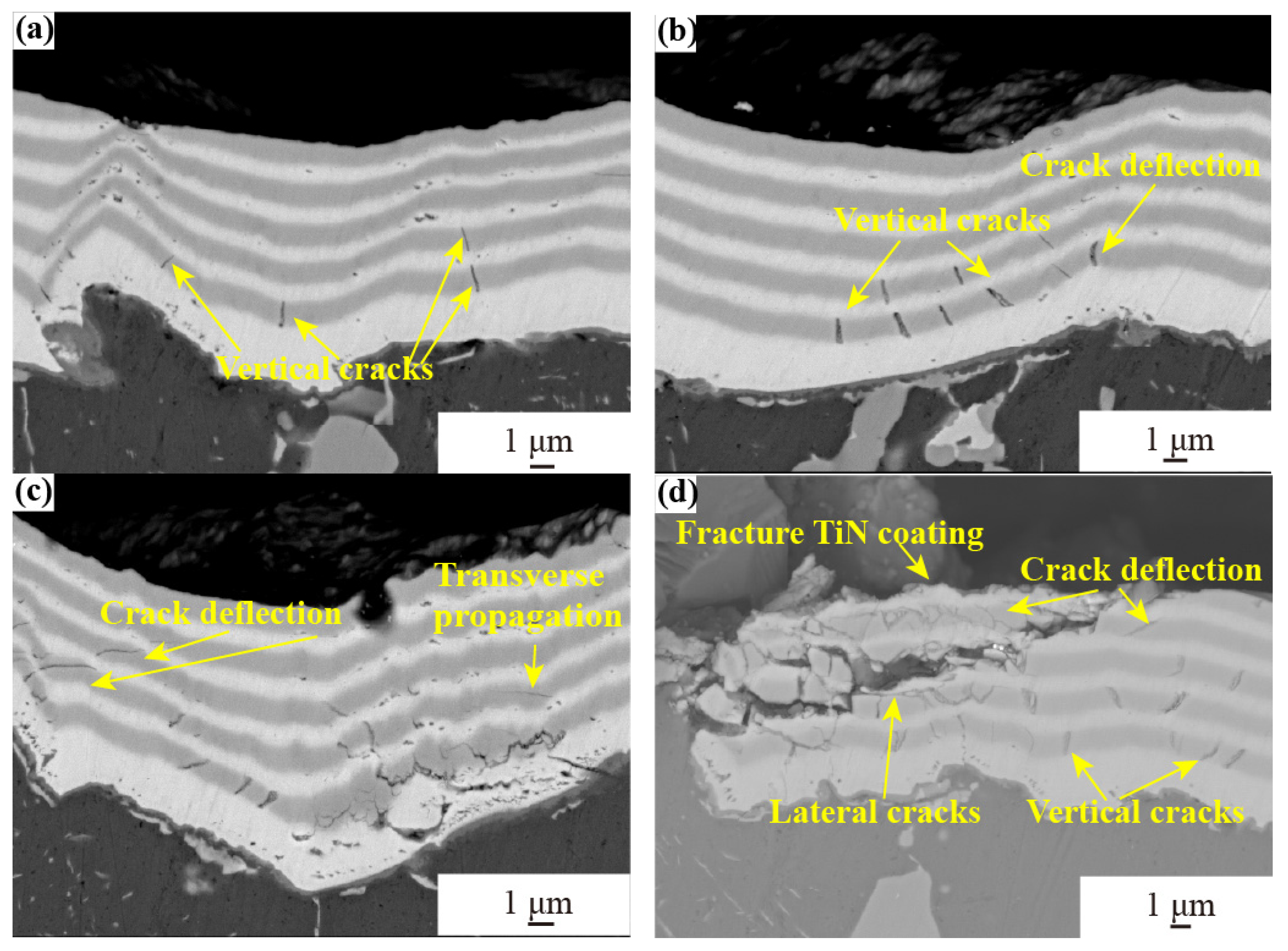
Under a 90° incident angle, TiN/Ti-1:4 coating experienced transverse cracks earlier, while the TiN/Ti-4:1 ratio coating showed a cross phenomenon between cracks earlier, resulting in more severe damage in the later stage of erosion. The TiN/Ti-1:4 coating peeled layer-by-layer due to the thicker Ti layer, which improved resistance to crack expansion. The TiN/Ti-4:1 coating experienced complete spalling as a failure form.
(5)
Under a 45° incident angle, cracks formed and intersected in the inner TiN layer in TiN/Ti-1:1 and TiN/Ti-4:1. The failure mechanism of both coatings was layer-by-layer spallation.
This study of TiN/Ti multilayer coatings is beneficial in enhancing the erosion resistance of aluminum alloys, improving the service performance of aluminum alloy turbocharger impellers in desert environments, and minimizing damage from erosion wear on aluminum alloy impellers.

Author Contributions

Methodology, Y.R.; Validation, Z.Y. and Y.Z.; Formal analysis, Z.Z. (Zilei Zhang); Resources, G.H.; Writing—original draft, Z.Z. (Zhaolu Zhang). All authors have read and agreed to the published version of the manuscript.

Funding

This research was funded by the Shaanxi Province Postdoctoral Science Foundation (No. 31271000000082).

Institutional Review Board Statement

Not applicable.

Informed Consent Statement

Not applicable.

Data Availability Statement

Data is contained within the article.

Conflicts of Interest

The authors declare no conflict of interest.

References

  1. Roa, J.J.; Jiménez-Piqué, E.; Martínez, R.; Ramírez, G.; Tarragó, J.M.; Rodríguez, R.; Llanes, L. Contact Damage and Fracture Micromechanisms of Multilayered TiN/CrN Coatings at Micro- and Nano-Length Scales. Thin Solid Films 2014, 571, 308–315. [Google Scholar] [CrossRef]
  2. Hajjioui, E.A.; Bouchaala, K.; Faqir, M.; Essadiqi, E. A Review of Manufacturing Processes, Mechanical Properties and Precipitations for Aluminum Lithium Alloys Used in Aeronautic Applications. Heliyon 2023, 9, e12565. [Google Scholar] [CrossRef]
  3. Zhang, J.; Song, B.; Wei, Q.; Bourell, D.; Shi, Y. A Review of Selective Laser Melting of Aluminum Alloys: Processing, Microstructure, Property and Developing Trends. J. Mater. Sci. Technol. 2019, 35, 270–284. [Google Scholar] [CrossRef]
  4. Zafar, H.; Khushaim, M.; Ravaux, F.; Anjum, D.H. Scale-Dependent Structure-Property Correlations of Precipitation-Hardened Aluminum Alloys: A Review. JOM 2022, 74, 361–380. [Google Scholar] [CrossRef]
  5. Krella, A.K.; Czyżniewski, A.; Gilewicz, A.; Krupa, A. Cavitation Erosion of CrN/CrCN Multilayer Coating. Wear 2017, 386–387, 80–89. [Google Scholar] [CrossRef]
  6. Beake, B.D.; Isern, L.; Endrino, J.L.; Fox-Rabinovich, G.S. Micro-Impact Testing of AlTiN and TiAlCrN Coatings. Wear 2019, 418–419, 102–110. [Google Scholar] [CrossRef]
  7. Wieciński, P.; Smolik, J.; Garbacz, H.; Kurzydłowski, K.J. Erosion Resistance of the Nanostructured Cr/CrN Multilayer Coatings on Ti6Al4V Alloy. Vacuum 2014, 107, 277–283. [Google Scholar] [CrossRef]
  8. Wu, Y.; Li, Z.; Yang, W.; Zhu, S.; Meng, X.; Cai, Z. Fretting Wear Behavior of Ti/TiN Multilayer Film on Uranium Surface under Various Displacement Amplitudes. Trans. Nonferrous Met. Soc. China 2018, 28, 1593–1601. [Google Scholar] [CrossRef]
  9. Kravchenko, Y.O.; Iatsunskyi, I.; Maksakova, O.; Natalich, B.; Dvornichenko, A.; Pogrebnjak, A.D.; Borysiuk, V.N. Experimental and Numerical Study of Multicomponent Nitride Coatings Based on TiAlSiY Fabricated by CA-PVD Method. Mater. Res. Express 2019, 6, 066406. [Google Scholar] [CrossRef]
  10. Skoric, B.; Kakas, D.; Bibic, N.; Rakita, M. Microstructural Studies of TiN Coatings Prepared by PVD and MAD. Surf. Sci. 2004, 566, 40–44. [Google Scholar] [CrossRef]
  11. Zhang, Y.; Wang, Q.; Ramachandran, C.S.; Guo, P.; Wang, A. Microstructure and Performance of High-Velocity Oxygen-Fuel Coupled Physical Vapor Deposition (HVOF-PVD) Duplex Protective Coatings: A Review. Coatings 2022, 12, 1395. [Google Scholar] [CrossRef]
  12. Elyutin, A.V.; Blinkov, I.V.; Volkhonsky, A.O.; Belov, D.S. Properties of Nanocrystalline Arc PVD TiN-Cu Coatings. Inorg. Mater. 2013, 49, 1106–1112. [Google Scholar] [CrossRef]
  13. Cao, X.; He, W.; Liao, B.; Zhou, H.; Zhang, H.; Tan, C.; Yang, Z. Sand Particle Erosion Resistance of the Multilayer Gradient TiN/Ti Coatings on Ti6Al4V Alloy. Surf. Coat. Technol. 2019, 365, 214–221. [Google Scholar] [CrossRef]
  14. Cao, H.; Yang, J.; Luo, W.; Li, Y.; Qi, F.; Zhao, N.; Lu, L.; Ouyang, X. Influence of Film Structure on the Microstructure and Properties of TiAlN Coatings on Al-Si Alloys. Mater. Charact. 2022, 189, 111996. [Google Scholar] [CrossRef]
  15. Xu, F.; Gong, D. Improved the Elevated Temperature Mechanical Properties of Al-Si Alloy Deposited with Al-Si Coating by Magnetron Sputtering. Vacuum 2018, 150, 1–7. [Google Scholar] [CrossRef]
  16. Cai, F.; Huang, X.; Yang, Q.; Nagy, D. Tribological Behaviors of Titanium Nitride- and Chromium-Nitride-Based Physical Vapor Deposition Coating Systems. J. Eng. Gas Turbines Power 2012, 134, 112504. [Google Scholar] [CrossRef]
  17. Feuerstein, A.; Kleyman, A. Ti–N Multilayer Systems for Compressor Airfoil Sand Erosion Protection. Surf. Coat. Technol. 2009, 204, 1092–1096. [Google Scholar] [CrossRef]
  18. Parameswaran, V.R.; Immarigeon, J.-P.; Nagy, D. Titanium Nitride Coating for Aero Engine Compressor Gas Path Components. Surf. Coat. Technol. 1992, 52, 251–260. [Google Scholar] [CrossRef]
  19. Ward, L.P.; Purushotham, K.P.; Manory, R.R. Studies on the Surface Modification of TiN Coatings Using MEVVA Ion Implantation with Selected Metallic Species. Nucl. Instrum. METHODS Phys. Res. Sect. B-BEAM Interact. Mater. At. 2016, 368, 37–44. [Google Scholar] [CrossRef]
  20. Babur, M.Z.; Iqbal, Z.; Shafiq, M.; Naz, M.Y.; Makhlouf, M.M. Hybrid TiN-CCPN Coating of AISI-201 Stainless Steel by Physical Vapor Deposition Combined with Cathodic Cage Plasma Nitriding for Improved Tribological Properties. J. Build. Eng. 2022, 45, 103512. [Google Scholar] [CrossRef]
  21. Demchyshyn, A.V.; Kurapov, Y.A.; Michenko, V.A.; Kostin, Y.G.; Goncharov, A.A.; Ternovoi, Y.G. Linear Vacuum ARC Evaporators for Deposition of Functional Multi-Purpose Coatings. In Emerging Applications of Vacuum-Arc-Produced Plasma, Ion and Electron Beams; Oks, E., Brown, I., Eds.; NATO Science Series; Springer Netherlands: Dordrecht, The Netherlands, 2002; pp. 131–149. ISBN 978-94-010-0277-6. [Google Scholar]
  22. Chen, J.; Li, H.; Beake, B.D. Load Sensitivity in Repetitive Nano-Impact Testing of TiN and AlTiN Coatings. Surf. Coat. Technol. 2016, 308, 289–297. [Google Scholar] [CrossRef]
  23. Cheng, Y.H.; Browne, T.; Heckerman, B.; Bowman, C.; Gorokhovsky, V.; Meletis, E.I. Mechanical and Tribological Properties of TiN/Ti Multilayer Coating. Surf. Coat. Technol. 2010, 205, 146–151. [Google Scholar] [CrossRef]
  24. Zhang, H.; Li, Z.; He, W.; Ma, C.; Liao, B.; Li, Y. Mechanical Modification and Damage Mechanism Evolution of TiN Films Subjected to Cyclic Nano-Impact by Adjusting N/Ti Ratios. J. Alloys Compd. 2019, 809, 151816. [Google Scholar] [CrossRef]
  25. Bousser, E.; Martinu, L.; Klemberg-Sapieha, J.E. Solid Particle Erosion Mechanisms of Hard Protective Coatings. Surf. Coat. Technol. 2013, 235, 383–393. [Google Scholar] [CrossRef]
  26. Borawski, B.; Singh, J.; Todd, J.A.; Wolfe, D.E. Multi-Layer Coating Design Architecture for Optimum Particulate Erosion Resistance. Wear 2011, 271, 2782–2792. [Google Scholar] [CrossRef]
  27. Iwai, Y.; Honda, T.; Yamada, H.; Matsubara, T.; Larsson, M.; Hogmark, S. Evaluation of Wear Resistance of Thin Hard Coatings by a New Solid Particle Impact Test. Wear 2001, 251, 861–867. [Google Scholar] [CrossRef]
  28. Borawski, B.; Todd, J.A.; Singh, J.; Wolfe, D.E. The Influence of Ductile Interlayer Material on the Particle Erosion Resistance of Multilayered TiN Based Coatings. Wear 2011, 271, 2890–2898. [Google Scholar] [CrossRef]
  29. Bromark, M.; Hedenqvist, P.; Hogmark, S. The Influence of Substrate Material on the Erosion Resistance of TiN Coated Tool Steels. Wear 1995, 186–187, 189–194. [Google Scholar] [CrossRef]
  30. Xue, X.; Wang, S.; Zeng, C.; Bai, H.; Li, L.; Wang, Z. Buckling-Delamination and Cracking of Thin Titanium Films under Compression: Experimental and Numerical Studies. Surf. Coat. Technol. 2014, 244, 151–157. [Google Scholar] [CrossRef]
  31. Cao, X.; He, W.; He, G.; Liao, B.; Zhang, H.; Chen, J.; Lv, C. Sand Erosion Resistance Improvement and Damage Mechanism of TiAlN Coating via the Bias-Graded Voltage in FCVA Deposition. Surf. Coat. Technol. 2019, 378, 125009. [Google Scholar] [CrossRef]
  32. Zhang, H.; Li, Z.; He, W.; Liao, B.; He, G.; Cao, X.; Li, Y. Damage Evolution and Mechanism of TiN/Ti Multilayer Coatings in Sand Erosion Condition. Surf. Coat. Technol. 2018, 353, 210–220. [Google Scholar] [CrossRef]
  33. Zhang, H.; Li, Z.; He, W.; Ma, C.; Chen, J.; Liao, B.; Li, Y. Damage Mechanisms Evolution of TiN/Ti Multilayer Films with Different Modulation Periods in Cyclic Impact Conditions. Appl. Surf. Sci. 2021, 540, 148366. [Google Scholar] [CrossRef]
  34. Budinski, K.G. Tribological Properties of Titanium Alloys. Wear 1991, 151, 203–217. [Google Scholar] [CrossRef]
  35. Trapezon, A.G.; Lyashenko, B.A.; Lysenkov, M.O. Fatigue Strength of Metals with Hardening Coatings (Review). STRENGTH Mater. 2013, 45, 284–294. [Google Scholar] [CrossRef]
Figure 1. Surface morphology of TiN/Ti-4:1 (a), TiN/Ti-1:1 (b), and TiN/Ti-1:4 (c).
Coatings 13 02074 g001
Figure 2. Surface roughness values of TiN/Ti-4:1, TiN/Ti-1:1, and TiN/Ti-1:4.
Coatings 13 02074 g002
Figure 3. The thickness of TiN/Ti multilayer coatings at different modulation ratios of (a) 4:1, (b) 1:1, and (c) 1:4.
Coatings 13 02074 g003
Figure 4. XRD of TiN/Ti multilayer coatings at different modulation ratios.
Coatings 13 02074 g004
Figure 5. (a) Hardness and elastic modulus values of TiN/Ti-4:1, TiN/Ti-1:1, and TiN/Ti-1:4. (b) H3/E2 values of TiN/Ti-4:1, TiN/Ti-1:1, and TiN/Ti-1:4.
Coatings 13 02074 g005
Figure 6. (a) Scratch morphology of the TiN/Ti-1:1 multilayer coating. (b) Adhesion force of the TiN/Ti multilayer coatings deposited on aluminum.
Coatings 13 02074 g006
Figure 7. Mass loss curves of TiN/Ti-4:1 (a), TiN/Ti-1:1 (b), and TiN/Ti-1:4 (c) coatings at a 90° erosion angle and (d) 2A70 aluminum.
Coatings 13 02074 g007
Figure 8. Erosion loss rates of the TiN/Ti multilayer coatings at a 90° erosion angle with different modulation ratios.
Coatings 13 02074 g008
Figure 9. Typical surface erosion morphology of TiN/Ti multilayer coatings.
Coatings 13 02074 g009
Figure 10. Failure process of the TiN/Ti-1:4 coating at different sand supplies: (a) 2.3 g, (b) 6.9 g, and (c) 11.5 g.
Coatings 13 02074 g010
Figure 11. Failure process of the TiN/Ti-4:1 coatings at different sand supplies: (a) 2.3 g, (b) 4.6 g, (c) 6.9 g, and (d) 11.5 g.
Coatings 13 02074 g011
Figure 12. (a) Erosion loss rates of the TiN/Ti multilayer coatings under 90°. (b) Typical surface erosion morphology of the TiN/Ti-1:1 multilayer coatings. (c) Enlarged view of the yellow dashed square in (b).
Coatings 13 02074 g012
Figure 13. Failure process of the TiN/Ti-1:1 coatings at different sand supplies: (a) 2.3 g, (b) 4.6 g, (c) 6.9 g, and (d) 11.5 g.
Coatings 13 02074 g013
Figure 14. Failure process of the TiN/Ti-4:1 coatings at different sand supplies: (a) 2.3 g, (b) 4.6 g, (c) 6.9 g, and (d) 11.5 g.
Coatings 13 02074 g014
Table 1. Chemical composition of Ti and N in each coating (at.%).
Modulation RatioTiN
4:153.846.2
1:158.641.4
1:452.247.8
Disclaimer/Publisher’s Note: The statements, opinions and data contained in all publications are solely those of the individual author(s) and contributor(s) and not of MDPI and/or the editor(s). MDPI and/or the editor(s) disclaim responsibility for any injury to people or property resulting from any ideas, methods, instructions or products referred to in the content.

