
Effects of Graphene Oxide on Tribological Properties of Micro-Arc Oxidation Coatings on Ti-6Al-4V


State Key Laboratory of Mechanics and Control of Mechanical Structures, Nanjing University of Aeronautics and Astronautics, Nanjing 210016, China
*
Author to whom correspondence should be addressed.
Coatings 2023, 13(11), 1967; https://doi.org/10.3390/coatings13111967
Submission received: 19 October 2023
/
Revised: 12 November 2023
/
Accepted: 17 November 2023
/
Published: 19 November 2023
(This article belongs to the Special Issue Tribological Behavior and Mechanical Performance of Coatings and Materials)
Abstract
:This paper investigates the effect of graphene oxide (GO) particles on the friction reduction and wear resistance of coatings on a Ti-6Al-4V alloy generated using the micro-arc oxidation (MAO) technique. Different concentrations of GO were added in aluminate–phosphate electrolyte. The composition of the MAO coatings was investigated using X-ray diffraction and the energy dispersive spectrum. Measurements of the coating’s thickness, hardness, and roughness have also been conducted. Ball-on-disk friction tests under dry conditions were carried out to reveal the tribological behavior of the MAO coating. The results showed that the coating consisted of Al2TiO5 and γ-Al2O3. The addition of GO greatly reduced the friction coefficient by 25%. The coating with 5 g/L of GO particles exhibited the lowest friction coefficient (reduced from 0.47 to 0.35). Moreover, the coating thickness become thicker (from 10 to 20 μm) with an increase in GO concentration from 0 to 10 g/L. The wear mechanism was revealed via worn surface analysis. This study provides a helpful way to improve the surface wear resistance of titanium alloys.
1. Introduction
Due to their exceptional strength-to-weight ratio, remarkable corrosion resistance, and outstanding biocompatibility, titanium alloys have found extensive utilization within the aerospace, maritime, and biomedical sectors [1]. The TC4 titanium alloy presently stands as the most extensively employed α + β titanium alloy, with its quantity constituting more than half of the total consumption of titanium alloys [2]. Components crafted from titanium alloys frequently experience tribological interactions with various media, whether subjected to static or dynamic loads [1]. The inadequate tribological characteristics of titanium alloys, including a low surface hardness, elevated friction coefficients, and limited wear resistance, have constrained their application scope [3]. Various surface engineering techniques have been applied to titanium alloys, including methodologies such as surface oxidation, and physical vapor deposition (PVD) and chemical vapor deposition (CVD) coatings, as well as ion implantation, among other methods [4]. Nevertheless, these methodologies are associated with high costs and often result in the production of relatively thin surface layers. Anodic oxidation, as the most widely used technique for surface modification in titanium alloys, typically yields thin films comprising either amorphous hydrated oxides or crystalline TiO2 in the anatase phase, which may not offer sufficient load-bearing capacity when subjected to heavy loads [5,6].
Micro-arc oxidation (MAO), also known as plasma electrolytic oxidation (PEO), is an eco-friendly technology employed for the generation of ceramic coatings characterized by strong adhesion on valve metals such as aluminum (Al), titanium (Ti), magnesium (Mg), zirconium (Zr), and their alloys [7]. This technique is similar to metal anodic oxidation within an electrolytic solution, employing voltages that induce plasma micro discharges at the electrode’s surface. This film is altered by means of micro-discharges, which are initiated at potentials surpassing the breakdown voltage of the developing oxide film and then swiftly traverse the anode surface [8]. Simultaneously, the local temperature and pressure within the discharge channel can achieve temperatures of 103–104 Kelvin and pressures of 102–103 MPa [9]. These conditions reach a level where they prompt thermal and electrochemical interactions between the substrate and the electrolyte [10]. As a consequence of these interactions, the surface undergoes the generation of high-temperature oxide and intricate compound formations through the melting and quenching process. These compounds comprise oxides originating from both the substrate material and the elements from the electrolyte [11]. These coatings typically exhibit high wear resistance due to their high hardness; however, they also tend to demonstrate high friction levels under dry friction conditions [12]. The characteristics and quality of the ceramic coatings can be tailored via altering the electrolyte composition, various electrical parameters, and the process time [13].
Researchers have attempted to improve the lubrication performance and enhance the wear resistance of the coatings by synthesizing self-lubricating coatings through a one-step process in lubricant-containing solutions [14]. Chang et al. [15] reported that good adhesion and better tribological properties can be obtained for the MAO-grown coatings via the incorporation of MoS2 particles into the electrolyte. Liu et al. [16] prepared a composite coating containing graphene nanosheets and TiO2 on Ti-6Al-4V alloy. The addition of graphene provides a higher hardness and smoother surface, resulting in improved wear resistance. Zhang and coworkers [17] investigated the effect of graphene oxide (GO) on the tribological and corrosion behavior of magnesium alloys, showing that adding GO blocked part of the micropores and rendered the coating more compact and even.
Graphene oxide represents an intermediate byproduct arising during the production of graphene through the oxidation of graphite. It belongs to the class of two-dimensional materials like graphene [18]. GO is inherently hydrophilic, owing to the presence of oxygenated functional groups, including hydroxyl, epoxide, and carboxyl moieties, which significantly broaden its utility [19]. Research has already demonstrated that adding GO to the solution can significantly enhance the tribological behavior of MAO coatings prepared on magnesium and aluminum alloys [20,21]. Grigoriev and coworkers [18] reported that after incorporating 0.1 g/L, 0.3 g/L, 0.5 g/L GO particles in the silicate–hypophosphite electrolyte and micro-arc oxidizing for 30 min, respectively, the friction coefficient was slightly reduced from 0.73 to 0.69, and the hardness of the coating increased from 331 to 366 HV. Despite advancements, the lubricating performance and hardness of the coating still remain inadequate for some specialized applications. Consequently, this gap in performance calls for continued research into the development of coatings with lower coefficients of friction and a greater hardness.
Currently, there is limited research regarding the influence of high GO concentrations on MAO coatings prepared in aluminate electrolyte for titanium alloys. This study aims to investigate how the inclusion of GO additives in the aluminate-phosphate electrolyte influences the phase composition, surface morphology, and tribological characteristics of coatings generated through the micro-arc oxidation process on the Ti-6Al-4V titanium alloy.
2. Experimental Details
2.1. Material and MAO Procedure
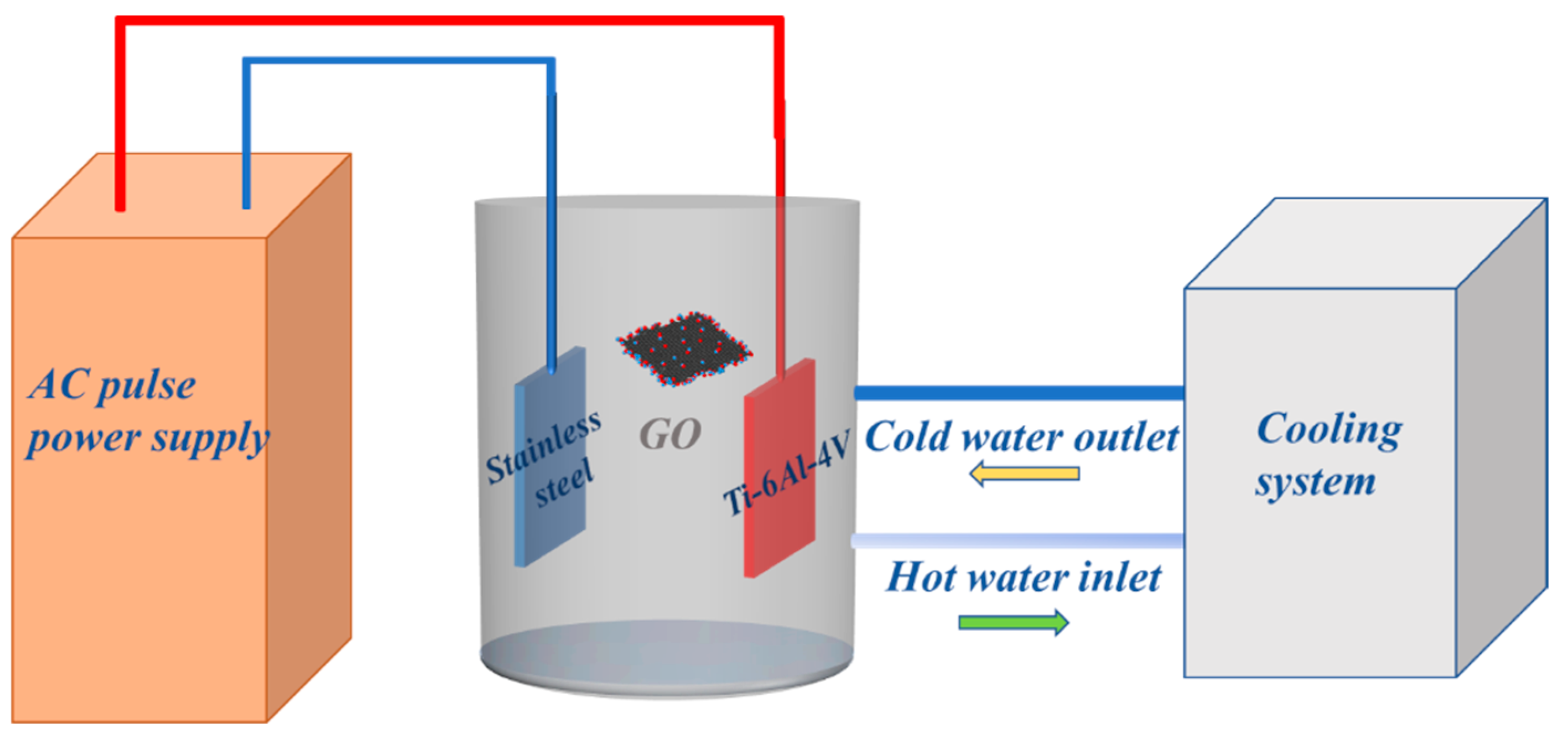
The Ti-6Al-4V alloys (5.8%–6.55% Al, 3.6%–4.4% V, 0%–0.2% Fe, 0%–0.3% O, and balance Ti) with a size of 50 × 20 × 1 mm3 were subjected to grinding and polishing using SiC abrasive paper to achieve a desired average surface roughness Ra ≈ 1.0 μm. Then, the specimens were cleaned in distilled water, subjected to ultrasonic degreasing in alcohol and, finally, air-dried in a warm air environment. A pulse power supply (MAT-WH30A-T, Microarc Age, Nanjing, China) was used to perform MAO treatment at a constant voltage of 350 V, frequency of 100 Hz, and 10% duty cycle for 20 min in a water-cooling bath with stainless steel as the cathode. The Ti-6Al-4V alloy sample was connected to the anode. The schematic diagram of the device is shown in Figure 1. Aqueous solutions of electrolytes were prepared using chemically pure NaAlO2 and Na3PO4, and the concentration was 30 g/L NaAlO2 and 5 g/L Na3PO4. The temperature was maintained between 17 and 19 °C. The electrolyte was incorporated with distinct GO concentrations of 0, 1, 3, 5, 10 g/L, with a magnetic stirrer operating to disperse GO particles, with particle sizes ranging from 10 to 40 nanometers. The ceramic coatings produced in the electrolyte containing 0, 1, 3, 5, 10 g/L GO were named as S0, S1, S3, S5, S10, respectively. After the treatment, the coated samples were rinsed with water and subsequently dried using warm air.
2.2. Composition and Microstructure Analysis
The composition of coatings was explored using a Malvern Panalytical Empyrean X-ray diffractometer (Cu Kα radiation) with the step size of 0.02° and a scan range of 20°–80°. The X-ray generator settings were 30 kV and 40 mA. A SEM (LYRA3 GM, TESCAN, Brno, Czech Republic) was employed to observe the surface and cross-sectional microstructure. The thickness of each coating was measured at three points using an SEM, with the average of these measurements taken as the representative value. An energy dispersive spectrometer (EDS) attachment was used for qualitative element chemical analysis. Surface roughness was assessed using a profilometer (MFT-5000, RTEC, San Jose, CA, USA) at ten distinct positions on each coating. Following the removal of the highest and lowest values, the mean of the remaining measurements was computed as a representation of the surface roughness of the coatings.
2.3. Tribological Evaluation
The microhardness of the coatings was determined using a Vickers hardness tester (HV-1000Z, Leeb Testing Instrument, Chongqing, China) at a load of 1 kg. Ten distinct positions on each sample were tested, and the coating’s hardness is represented by the average value obtained after excluding the highest and lowest measurements. The tribological performance of the MAO films was assessed using a ball-on-disc tribometer (MFT-5000, RTEC, San Jose, CA, USA), which was carried out under a load of 3 N, 100 rpm, and a diameter of 6 mm. The counter ball was made of SiC, with a diameter of 6.35 mm, and the temperature was controlled to 20 ± 1 °C. After testing, wear scar morphologies were analyzed using SEM, and wear track widths were averaged from four measurements per scar using a profilometer (MFT-5000, RTEC, San Jose, CA, USA).
3. Results and Discussion
3.1. Phase Composition
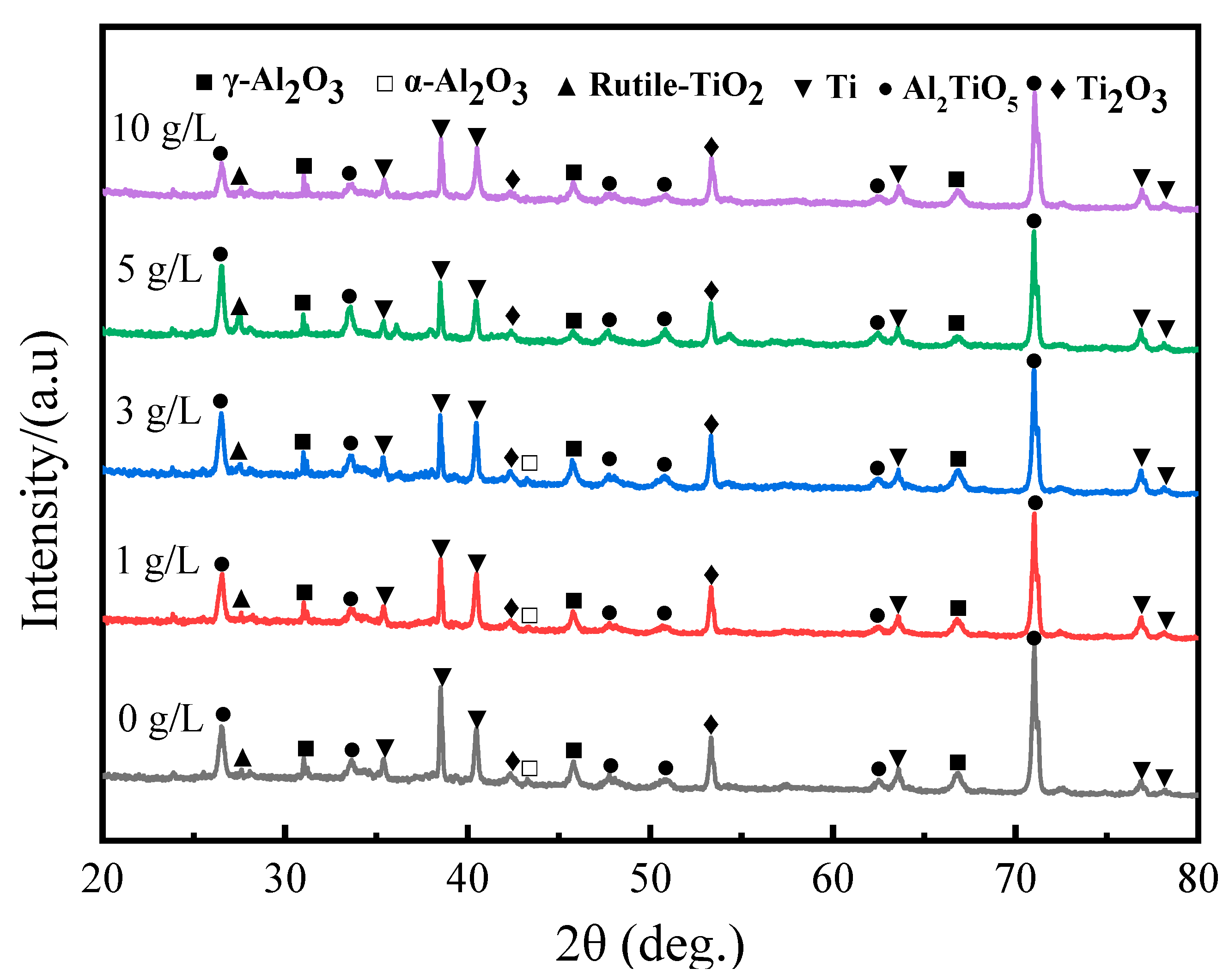
Figure 2 displays the X-ray diffraction results for MAO ceramic coatings prepared in electrolytes containing different amounts of GO. It is clear that the predominant composition of all the coatings is Al2TiO5, accompanied by a portion of γ-Al2O3 phase and minor quantities of low-valence titanium oxide. No GO-related phase was found due to its limited amount. In addition, a small amount of rutile TiO2 phase was also detected. Shokouhfar and coworkers [22] revealed the same phenomenon and implied that the low TiO2 content in the coatings prepared in aluminate-based solution could be attributed to the fact that the formation of Al2TiO5 consumes a significant portion of the produced TiO2. Minor amounts of α-Al2O3 were detected in S1, S2, and S3, which were prepared in electrolytes with relatively low GO concentrations. Furthermore, due to the thin thickness of the coatings, trace amounts of titanium were detected in all coatings. The same results were also reported by Liu et al. [16] in their study on the impact of graphene on the ceramic coatings formed on Ti-6Al-4V.
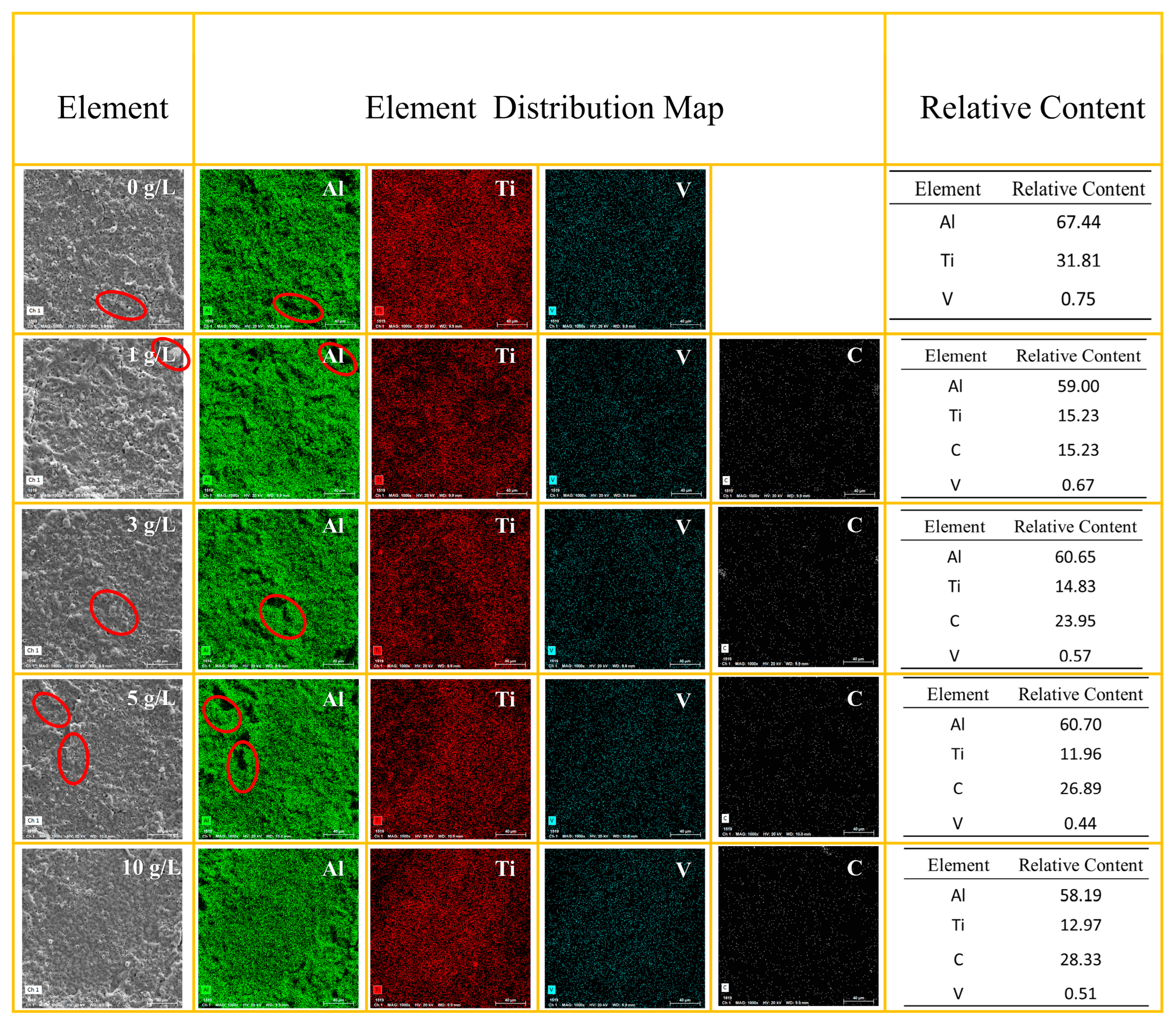
The relative contents of the elements Al, Ti, V, and C on the coating’s surface was analyzed via EDS, as shown in Figure 3. The results indicate that with the increasing concentration of GO particles in the solution, there is an upward trend in the relative carbon content within the coatings. Chen et al. [23] also reported a similar phenomenon in their study on the effect of graphite on coating composition. Furthermore, increasing the GO concentration has minimal impact on the Al content, but leads to a decrease in Ti content within the coating. The particle concentration does not exhibit a significant impact on the vanadium element content within the coatings.
Observing the distribution map of Al elements, it can be noticed that the content of Al elements is nearly zero in certain regions. When we combine this with SEM images, it becomes apparent that areas with a low Al content correspond to the noticeable bumps (shown using red circles) on the surface. This implies that the bump regions of the coating contain minimal aluminum oxides and, in turn, suggests that the predominant constituents of these areas are titanium oxides.
3.2. Coating Morphology
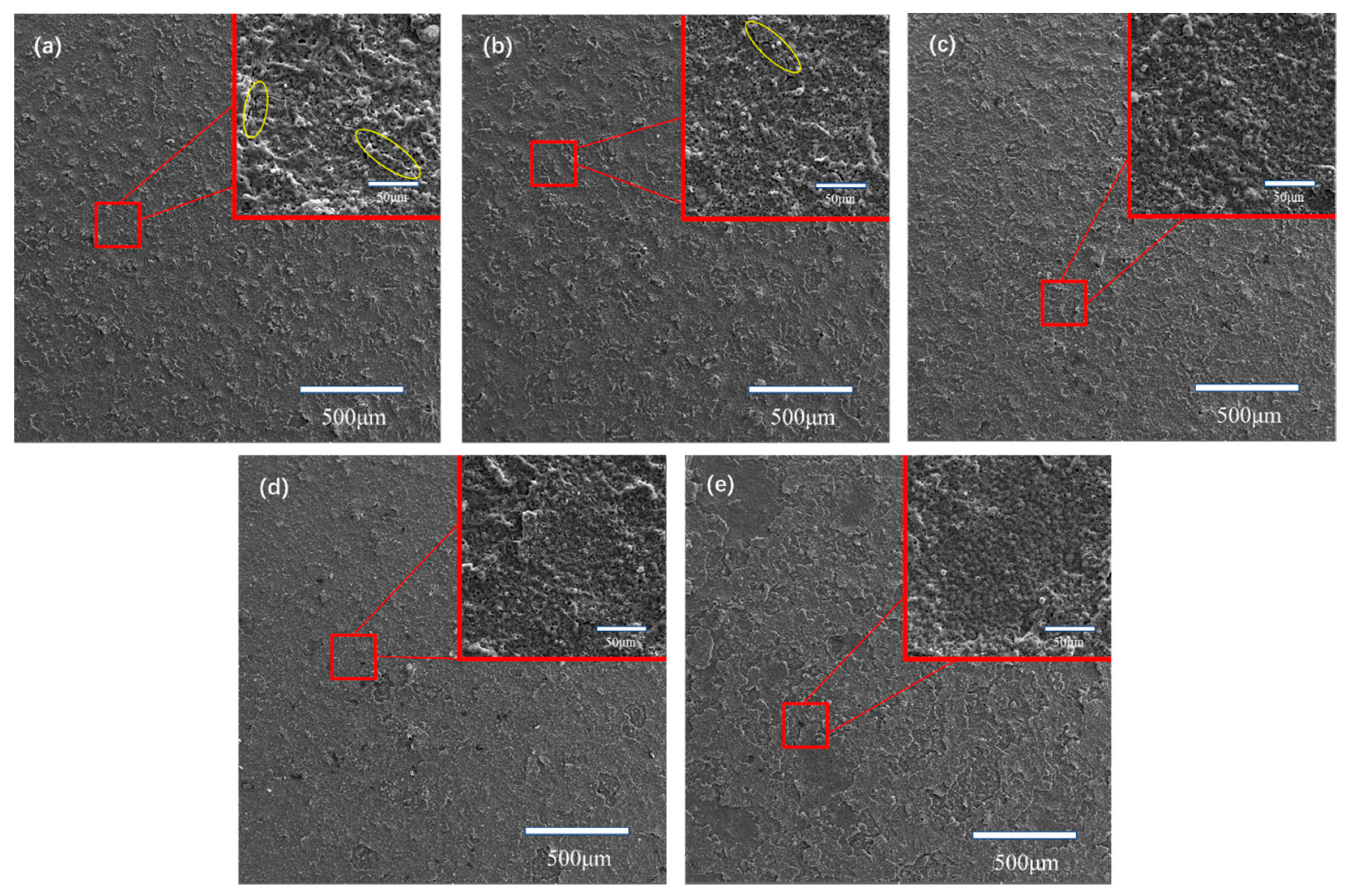
Figure 4 illustrates the surface characteristics of MAO coatings with different GO concentration levels. From the magnified images, it can be observed that a porous microstructure appeared in all MAO coatings. The presence of pores is a common characteristic in MAO coatings, as noted in previous research papers [23]. These micro pores were possibly produced via the eruption of melted material from the inner part of the coating and the emission of gas generated via the discharge-induced high temperature [24,25]. From Figure 4, it can be observed that the coatings prepared in a solution containing no GO have slightly larger pore sizes than the other coatings, and the pore sizes of coatings containing GO do not show significant differences.
Furthermore, obvious cracks can be observed in Figure 4a,b (as shown using yellow circles); the development of cracks can be attributed to the release of thermal stress that accumulates during the film growth process [22,26]. The cracks become smaller and less noticeable on the surface of S3, S4, and S5, which indicates that the addition of GO can decrease thermal stress in MAO treatment. The surface microstructure of the coating containing GO exhibits a noticeable enhancement compared to the GO-free coating, which can be attributed to the incorporation of graphene filling pores and the sealing of cracks [27]. However, when the GO concentration reaches 10 g/L, the coating surface exhibits a laminar structure, which is completely different from the other four coatings. This implies a relatively weak bonding strength between the layers. This can be attributed to the excessive incorporation of GO into the coating, which led to a reduction in the cohesive strength within the coating.
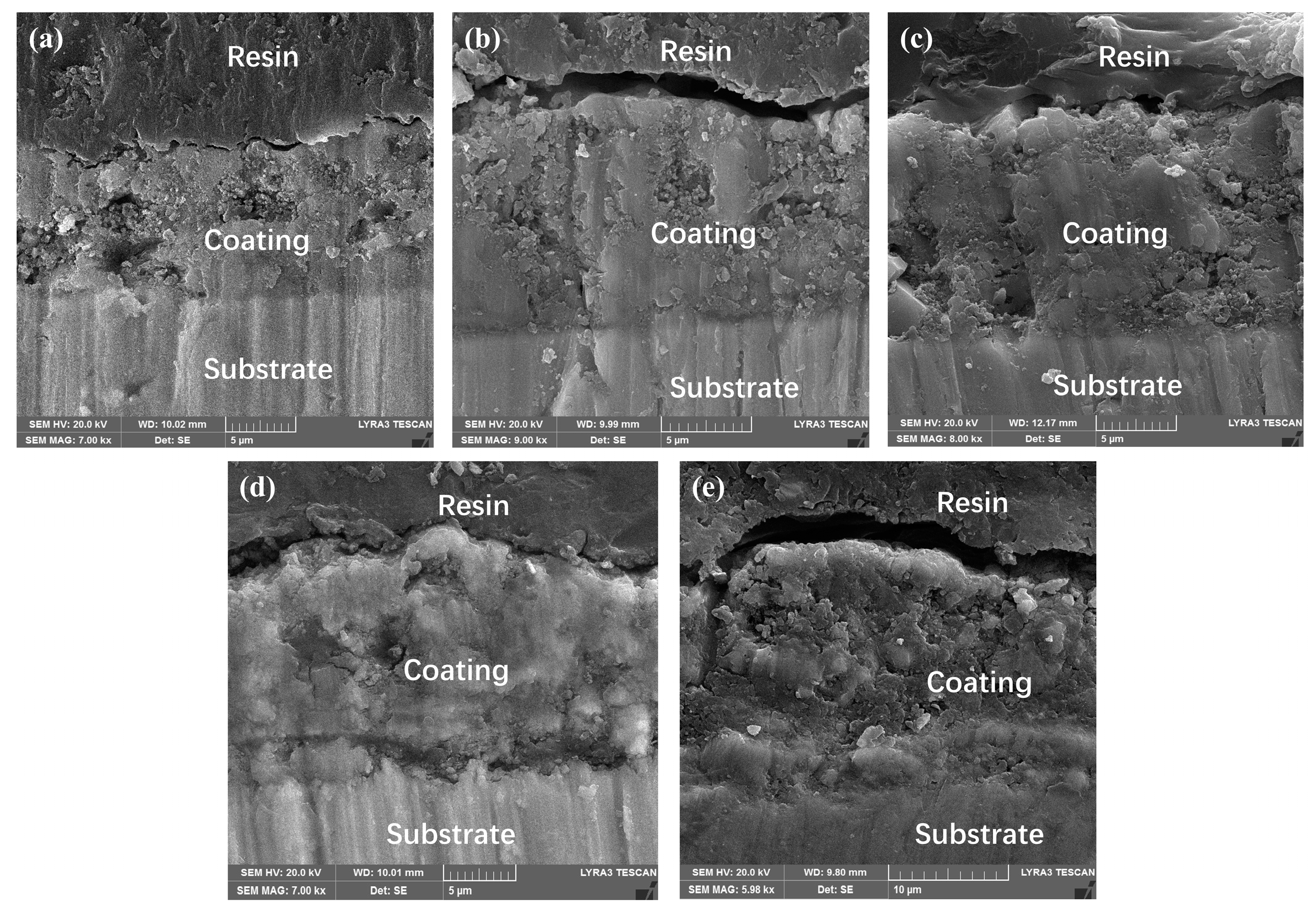
Figure 5 illustrates the cross-sectional microstructures of the ceramic coatings produced in electrolytes with varying concentrations of GO particles. As shown in Figure 5, all coatings exhibited a relatively uniform thickness. Several cavities can be clearly seen within coating S1, whereas no significant pores were observed in the cross-sectional image of the coating prepared in the electrolyte containing GO. This suggests that the inclusion of GO can decrease the porosity of the coating, consequently enhancing its density. Shokouhfar and colleagues [22] postulated that nanoparticles could attain negative surface charges within the electrolyte and be electrostatically attracted to the positively charged substrate surface through electrophoretic mechanisms. These particles can fill in the pores and cracks and enter the coating during this process, rendering it denser. The introduction of GO particles into the electrolyte had a notable impact on the coating thickness. As evident from Table 1, it is apparent that the coatings exhibit an increased thickness as the concentration of GO rises. As the GO concentration reaches 10 g/L, the thickness rises above 21 μm, which is twice that of the coating produced in GO-free electrolyte. This is because, with the same thickness, the coating containing GO has a lower breakdown voltage due to its conductivity, so the coating containing GO needs to be thicker to stop the reaction at the same termination voltage.
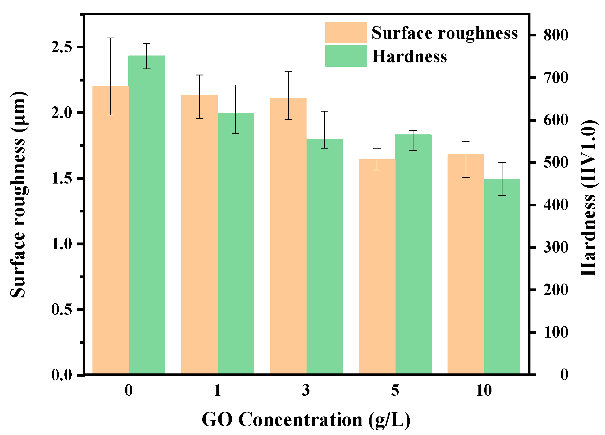
Figure 6 presents the surface roughness and hardness of the MAO coatings fabricated in electrolytes with varying concentrations of GO particles. The microhardness of the MAO coatings was determined using an LHV-1000 hardness tester, applying a load of 9.8 N to a Vickers indenter with a 10 s holding period. Coating S1 exhibits a higher hardness compared to the other coatings, and furthermore, with the increasing concentration of GO, the hardness of the coatings shows a decreasing trend. The GO particles were absorbed onto the anode surface due to cathaphoretic effects and, subsequently, integrated into the coating during the MAO procedure. GO disrupted the crystal structure of the coating, resulting in its discontinuity. Consequently, this led to a reduction in the cohesive strength of the coating, resulting in a reduced coating hardness. Ao and coworkers [28] also discovered a similar phenomenon regarding the impact of excessive hBN on the wear resistance of the coating. Their findings indicated that a high concentration of hBN resulted in a decline in the coating’s cohesive strength, leading to the decreased hardness of the coating and, subsequently, a reduced wear resistance. The roughness of coatings S1, S2, and S3 is quite similar, indicating that there is minimal impact on roughness when the particle content is relatively low. This aligns with the observations via SEM analysis shown in Figure 4. The roughness of S4 and S5 is about 0.5 microns lower than that of the coating prepared in a solution containing a low concentration of GO. The unbound particles within the electrolyte were attracted to the coating’s surface through electrophoretic effects, filling pores and sealing cracks, thereby leading to a decrease in the coating’s roughness.
3.3. Tribological Performance
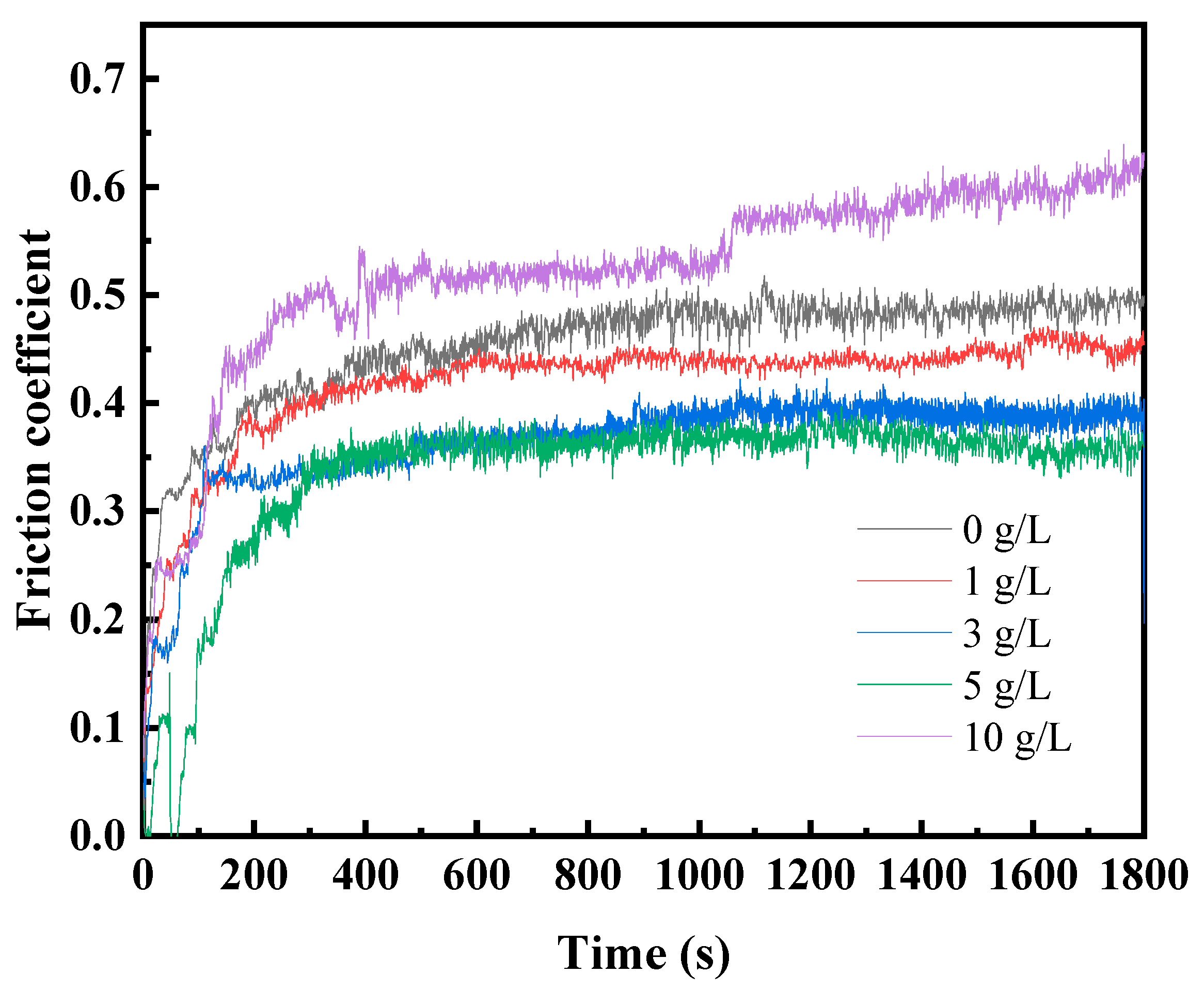
In Figure 7, the progression of the friction coefficient over the sliding time is presented under dry sliding conditions for coatings produced in electrolytes with various concentrations of GO. All coatings reached a relatively stable level of friction coefficient within five minutes. During the friction process, both the coating and the counterpart ball were continuously worn, resulting in an increasing contact area between them. This led to a gradual rise in the friction coefficient for all coatings over time. The friction coefficients of coatings S2, S3, and S4 all exhibit reduced values and a greater stability compared to those of the particle-free coating. As the GO concentration increased from 1 g/L to 5 g/L, the stable friction coefficients showed a decreasing trend. The incorporated GO in the coating was gradually released during the frictional process. The released GO formed a discontinuous deformed layer on the surface, and the transfer deformed layer worked as a lubricant, consequently reducing the friction coefficient. However, when the GO concentration reached 10 g/L, the friction coefficient become higher than that of the particle-free coating. An excess of particles adversely influenced the development of the composite coating, leading to a significant increase in the number of defects within the coating. As a result, the cohesive strength of the coating was reduced in comparison to the GO-free coating, ultimately leading to a higher friction coefficient.
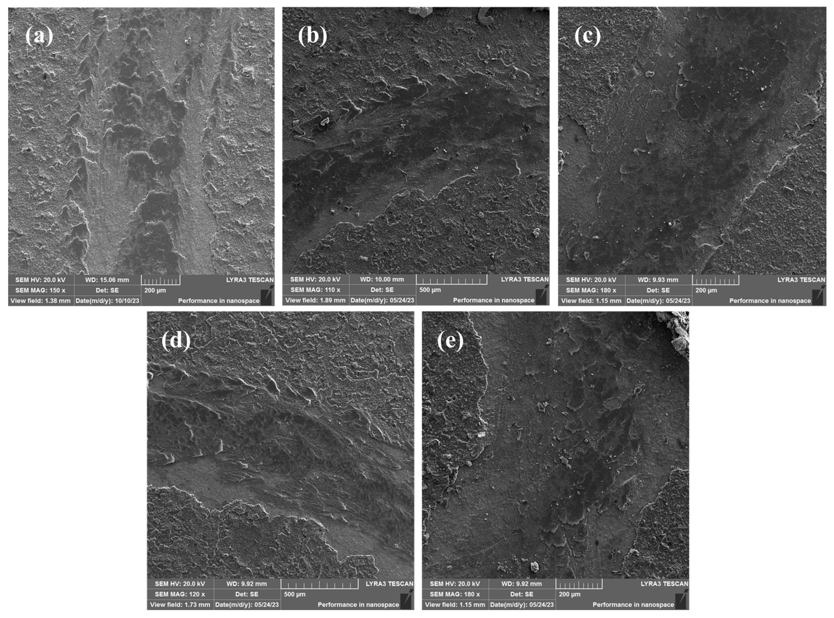
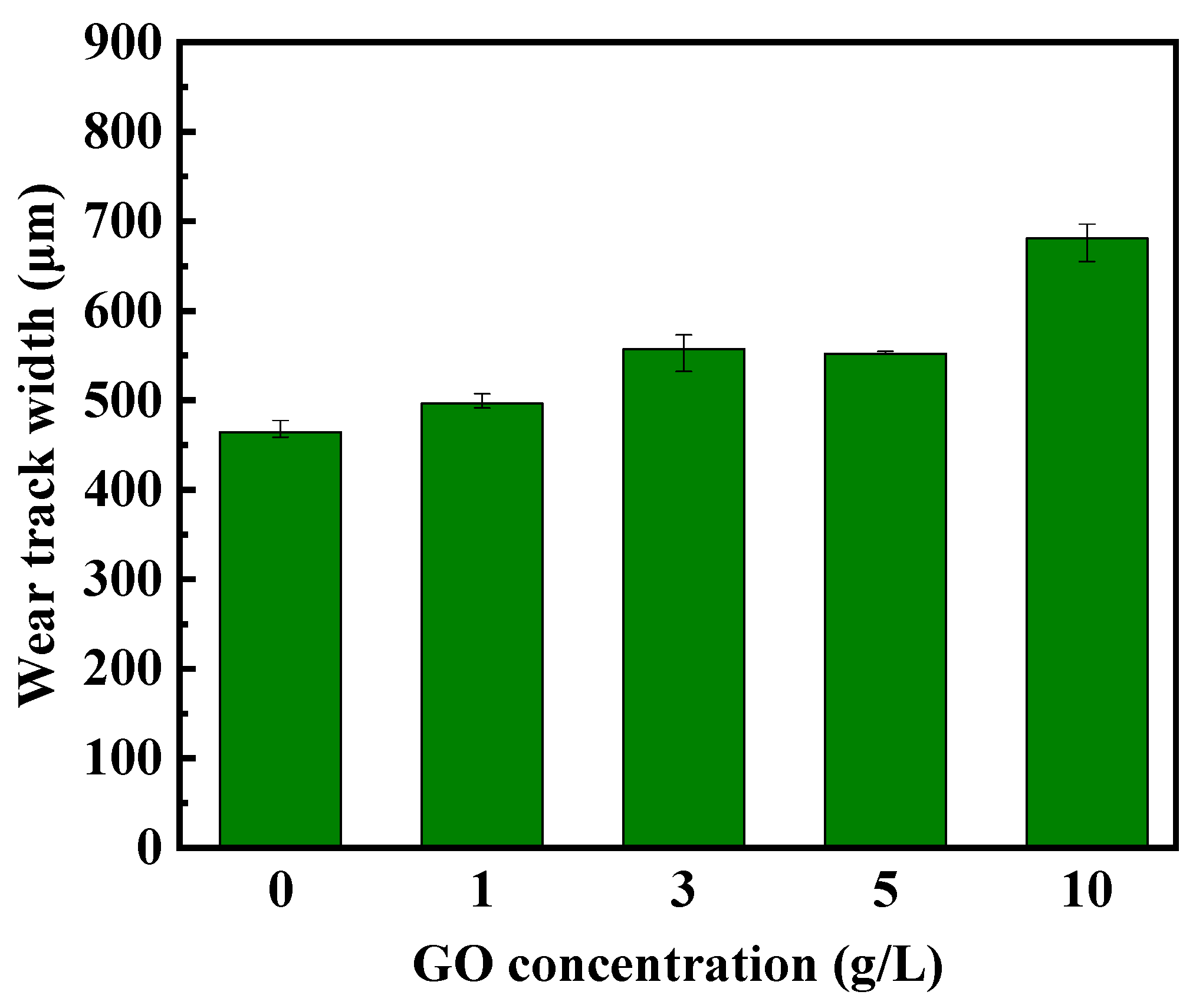
Figure 8 displays the scanning electron micrographs depicting the wear tracks formed on MAO coatings. It can be clearly observed that plastic deformations occurred at the central area of the wear scar on the S1 coating, whereas, in contrast, the GO-composite coatings do not show distinct adhesive damage, which revealed that the wear tracks were primarily caused by abrasive wear from ploughing. The wear scar width of different coatings is shown in Figure 9. As the concentration of GO increases, the wear scar width become larger. As depicted in Figure 9, a rise in the concentration of graphene oxide (GO) exhibits a negative correlation with the coating’s hardness. Coatings with a lower hardness are more susceptible to wear during the friction process, resulting in wider wear scars [29]. On the other hand, GO sheets act as lubricants during the friction process, thereby reducing adhesive damage in the friction process and lowering the friction coefficient [30].
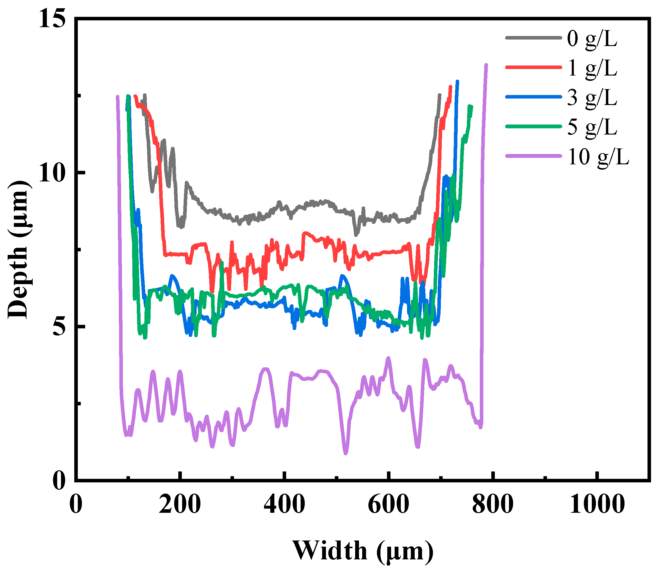
To explore the impact of GO concentration on the wear resistance performance of the coatings, the depth profiles of the wear tracks for each specimen were also measured and are presented in Figure 10. The profile images of the wear scars on the coatings clearly reveal the variations in wear scar depth with changing GO concentrations. The coating without GO exhibits the shallowest wear scar. As the concentration increases, both the depth and width of the wear scar slightly increase, which is consistent with the SEM results. The wear track depth and width of S3 and S4 show no significant difference, as their hardness is almost the same in Figure 6. When the GO concentration reaches 10 g/L, the wear scar depth is approximately twice that of S1. The observed differences in wear track depth among the various coatings demonstrate a strong correlation with their respective hardness. With increasing GO concentration, the coating’s hardness decreases, resulting in deeper wear scars during the friction process.
4. Conclusions
GO particles were effectively incorporated into MAO coatings on the Ti-6Al-4V alloy surface. The composite coating consisted mainly of Al2TiO5 and γ-Al2O3, with minor quantities of low-valence titanium oxide. The incorporation of GO into the coating formulation resulted in a reduction in the pore size and the number of microcracks. Furthermore, the presence of GO led to a thicker and denser coating. The friction coefficient decreased from 0.47 to 0.35 when the GO concentration in the electrolyte increased from 0 to 5 g/L. However, an increase in GO concentration caused a decrease in coating hardness, ranging from 600 to 450 HV, which reduced the wear resistance correspondingly. The integration of graphene oxide GO into the MAO electrolyte for the development of a self-lubricating coating with a low friction coefficient on the surface of a titanium alloy represents a novel and promising methodology. An essential area for future research will be directed toward improving the lubrication performance of microarc oxidation coatings without inducing a notable decline in coating hardness.
Author Contributions
Conceptualization, Q.H.; methodology, Q.D.; writing—original draft preparation, Q.H.; investigation, G.W.; formal analysis, X.L.; visualization, Y.R.; writing—review and editing, G.Z. All authors have read and agreed to the published version of the manuscript.
Funding
This project was financially supported by the National Natural Science Foundation of China (NSFC) (52075247, U2037603) and the Priority Academic Program Development of Jiangsu Higher Education Institutions (PAPD).
Institutional Review Board Statement
Not applicable.
Informed Consent Statement
Not applicable.
Data Availability Statement
The datasets used and/or analyzed during the current study are available from the corresponding author upon reasonable request.
Conflicts of Interest
The authors declare no conflict of interest.
References
- Yerokhin, A.L.; Nie, X.; Leyland, A.; Matthews, A. Characterization of oxide films produced by plasma electrolytic oxidation of a Ti–6Al–4V alloy. Surf. Coat. Technol. 2000, 130, 195–206. [Google Scholar] [CrossRef]
- Wheeler, J.M.; Collier, C.A.; Paillard, J.M.; Curran, J.A. Evaluation of micromechanical behaviour of plasma electrolytic oxidation (PEO) coatings on Ti–6Al–4V. Surf. Coat. Technol. 2010, 204, 3399–3409. [Google Scholar] [CrossRef]
- Zhai, D.; Feng, K.; Yue, H. Growth Kinetics of Microarc Oxidation TiO2 Ceramic Film on Ti6Al4V Alloy in Tetraborate Electrolyte. Metall. Mater. Trans. A 2019, 50, 2507–2518. [Google Scholar] [CrossRef]
- Li, Q.; Yang, W.; Liu, C.; Wang, D.; Liang, J. Correlations between the growth mechanism and properties of micro-arc oxidation coatings on titanium alloy: Effects of electrolytes. Surf. Coat. Technol. 2017, 316, 162–170. [Google Scholar] [CrossRef]
- Rakoch, A.G.; Gladkova, A.A.; Linn, Z.; Strekalina, D.M. The evidence of cathodic micro-discharges during plasma electrolytic oxidation of light metallic alloys and micro-discharge intensity depending on pH of the electrolyte. Surf. Coat. Technol. 2015, 269, 138–144. [Google Scholar] [CrossRef]
- Habazaki, H.; Tsunekawa, S.; Tsuji, E.; Nakayama, T. Formation and characterization of wear-resistant PEO coatings formed on β-titanium alloy at different electrolyte temperatures. Appl. Surf. Sci. 2012, 259, 711–718. [Google Scholar] [CrossRef]
- Yin, X.; Wang, Y.; Liu, B.; Luo, X.B. Effects of the grain boundary on phase structure and surface morphology of TiO2 films prepared by MAO technology. Surf. Interface Anal. 2012, 44, 276–281. [Google Scholar] [CrossRef]
- Aliasghari, S.; Skeldon, P.; Thompson, G.E. Plasma electrolytic oxidation of titanium in a phosphate/silicate electrolyte and tribological performance of the coatings. Appl. Surf. Sci. 2014, 316, 463–476. [Google Scholar] [CrossRef]
- Matykina, E.; Berkani, A.; Skeldon, P.; Thompson, G.E. Real-time imaging of coating growth during plasma electrolytic oxidation of titanium. Electrochim. Acta 2007, 53, 1987–1994. [Google Scholar] [CrossRef]
- Wang, Y.; Jiang, B.; Lei, T.; Guo, L. Dependence of growth features of microarc oxidation coatings of titanium alloy on control modes of alternate pulse. Mater. Lett. 2004, 58, 1907–1911. [Google Scholar] [CrossRef]
- Sobolev, A.; Kossenko, A.; Borodianskiy, K. Study of the Effect of Current Pulse Frequency on Ti-6Al-4V Alloy Coating Formation by Micro Arc Oxidation. Materials 2019, 12, 3983. [Google Scholar] [CrossRef]
- Venkateswarlu, K.; Suresh, S.; Nagumothu, R.; Sreekanth, D.; Sandhyarani, M. Role of Electric Pulse Duty and Frequency on Properties of Micro-Arc Oxidized Titania Films Developed on Ti-6Al-4V. Mater. Sci. Forum 2013, 765, 688–692. [Google Scholar] [CrossRef]
- Wang, J.-H.; Wang, J.; Lu, Y.; Du, M.-H.; Han, F.-Z. Effects of single pulse energy on the properties of ceramic coating prepared by micro-arc oxidation on Ti alloy. Appl. Surf. Sci. 2015, 324, 405–413. [Google Scholar] [CrossRef]
- Martin, J.; Melhem, A.; Shchedrina, I.; Duchanoy, T.; Nominé, A.; Henrion, G.; Czerwiec, T.; Belmonte, T. Effects of electrical parameters on plasma electrolytic oxidation of aluminium. Surf. Coat. Technol. 2013, 221, 70–76. [Google Scholar] [CrossRef]
- Chang, F.-C.; Wang, C.-J.; Lee, J.-W.; Lou, B.-S. Microstructure and mechanical properties evaluation of molybdenum disulfide-titania nanocomposite coatings grown by plasma electrolytic oxidation. Surf. Coat. Technol. 2016, 303, 68–77. [Google Scholar] [CrossRef]
- Liu, W.; Blawert, C.; Zheludkevich, M.L.; Lin, Y.; Talha, M.; Shi, Y.; Chen, L. Effects of graphene nanosheets on the ceramic coatings formed on Ti6Al4V alloy drill pipe by plasma electrolytic oxidation. J. Alloys Compd. 2019, 789, 996–1007. [Google Scholar] [CrossRef]
- Zhang, Y.; Chen, F.; Zhang, Y.; Du, C. Influence of graphene oxide additive on the tribological and electrochemical corrosion properties of a PEO coating prepared on AZ31 magnesium alloy. Tribol. Int. 2020, 146, 106135. [Google Scholar] [CrossRef]
- Grigoriev, S.; Peretyagin, N.; Apelfeld, A.; Smirnov, A.; Morozov, A.; Torskaya, E.; Volosova, M.; Yanushevich, O.; Yarygin, N.; Krikheli, N.; et al. Investigation of Tribological Characteristics of PEO Coatings Formed on Ti6Al4V Titanium Alloy in Electrolytes with Graphene Oxide Additives. Materials 2023, 16, 3928. [Google Scholar] [CrossRef] [PubMed]
- Shang, W.; Wu, F.; Wang, Y.; Rabiei Baboukani, A.; Wen, Y.; Jiang, J. Corrosion Resistance of Micro-Arc Oxidation/Graphene Oxide Composite Coatings on Magnesium Alloys. ACS Omega 2020, 5, 7262–7270. [Google Scholar] [CrossRef] [PubMed]
- Yang, W.; Xu, D.P.; Wang, J.L.; Jiang, B.L. Preparation of MAO coatings doped with graphene oxide. Surf. Eng. 2017, 33, 739–743. [Google Scholar] [CrossRef]
- Zhang, Y.; Chen, F.; Zhang, Y.; Liu, Z.; Wang, X.; Du, C. Influence of graphene oxide on the antiwear and antifriction performance of MAO coating fabricated on MgLi alloy. Surf. Coat. Technol. 2019, 364, 144–156. [Google Scholar] [CrossRef]
- Shokouhfar, M.; Allahkaram, S.R. Formation mechanism and surface characterization of ceramic composite coatings on pure titanium prepared by micro-arc oxidation in electrolytes containing nanoparticles. Surf. Coat. Technol. 2016, 291, 396–405. [Google Scholar] [CrossRef]
- Chen, X.; Hu, J.; Zhang, D.; Ren, P.; Liao, D.; Cai, L. Study on corrosion resistance of TC4 titanium alloy micro-arc oxidation/(PTFE + graphite) composite coating. Int. J. Appl. Ceram. Technol. 2022, 19, 397–408. [Google Scholar] [CrossRef]
- Ma, K.-J.; Al Bosta, M.M.S.; Wu, W.-T. Preparation of self-lubricating composite coatings through a micro-arc plasma oxidation with graphite in electrolyte solution. Surf. Coat. Technol. 2014, 259, 318–324. [Google Scholar] [CrossRef]
- Li, H.; Sun, Y.; Zhang, J. Effect of ZrO2 particle on the performance of micro-arc oxidation coatings on Ti6Al4V. Appl. Surf. Sci. 2015, 342, 183–190. [Google Scholar] [CrossRef]
- Xue, W.; Wang, C.; Chen, R.; Deng, Z. Structure and properties characterization of ceramic coatings produced on Ti–6Al–4V alloy by microarc oxidation in aluminate solution. Mater. Lett. 2002, 52, 435–441. [Google Scholar] [CrossRef]
- Fei, C.; Hai, Z.; Chen, C.; Yangjian, X. Study on the tribological performance of ceramic coatings on titanium alloy surfaces obtained through microarc oxidation. Prog. Org. Coat. 2009, 64, 264–267. [Google Scholar] [CrossRef]
- Ao, N.; Liu, D.; Wang, S.; Zhao, Q.; Zhang, X.; Zhang, M. Microstructure and Tribological Behavior of a TiO2/hBN Composite Ceramic Coating Formed via Micro-arc Oxidation of Ti–6Al–4V Alloy. J. Mater. Sci. Technol. 2016, 32, 1071–1076. [Google Scholar] [CrossRef]
- Martini, C.; Ceschini, L.; Tarterini, F.; Paillard, J.; Curran, J. PEO layers obtained from mixed aluminate–phosphate baths on Ti–6Al–4V: Dry sliding behaviour and influence of a PTFE topcoat. Wear 2010, 269, 747–756. [Google Scholar] [CrossRef]
- Wu, G.; Yin, Y.; Zhang, S.; Wang, Y.; Xiang, Y.; Li, L.; Yao, J. Effect of laser texturing on the antiwear properties of micro-arc oxidation coating formed on Ti-6Al-4V. Surf. Coat. Technol. 2023, 453, 129114. [Google Scholar] [CrossRef]
Figure 1.
The schematic diagram of the MAO processing device.

Figure 2.
XRD patterns of different MAO films.

Figure 3.
EDS analysis results for the surfaces of MAO coatings.

Figure 4.
Surface morphology and microstructure of the MAO coatings observed via SEM: (a) S1, (b) S2, (c) S3, (d) S4, and (e) S5.
Figure 4.
Surface morphology and microstructure of the MAO coatings observed via SEM: (a) S1, (b) S2, (c) S3, (d) S4, and (e) S5.

Figure 5.
Cross-section microstructure of MAO coatings: (a) S1, (b) S2, (c) S3, (d) S4, and (e) S5.

Figure 6.
Surface roughness and hardness of MAO coatings with different concentrations of GO.

Figure 7.
Friction coefficient of MAO coatings prepared with different concentrations of GO.

Figure 8.
The SEM images of wear tracks of the MAO coatings: (a) S1, (b) S2, (c) S3, (d) S4, and (e) S5.
Figure 8.
The SEM images of wear tracks of the MAO coatings: (a) S1, (b) S2, (c) S3, (d) S4, and (e) S5.

Figure 9.
Wear track width of the MAO coatings.

Figure 10.
Depth profiles of the wear tracks.


Table 1.
Thickness of the MAO coatings.
| Number | S1 | S2 | S3 | S4 | S5 |
|---|---|---|---|---|---|
| Average thickness (μm) | 10.4 | 13.2 | 15.1 | 16.6 | 21.8 |
Disclaimer/Publisher’s Note: The statements, opinions and data contained in all publications are solely those of the individual author(s) and contributor(s) and not of MDPI and/or the editor(s). MDPI and/or the editor(s) disclaim responsibility for any injury to people or property resulting from any ideas, methods, instructions or products referred to in the content. |
© 2023 by the authors. Licensee MDPI, Basel, Switzerland. This article is an open access article distributed under the terms and conditions of the Creative Commons Attribution (CC BY) license (https://creativecommons.org/licenses/by/4.0/).
Share and Cite
MDPI and ACS Style
Hu, Q.; Li, X.; Zhao, G.; Ruan, Y.; Wang, G.; Ding, Q. Effects of Graphene Oxide on Tribological Properties of Micro-Arc Oxidation Coatings on Ti-6Al-4V. Coatings 2023, 13, 1967. https://doi.org/10.3390/coatings13111967
AMA Style
Hu Q, Li X, Zhao G, Ruan Y, Wang G, Ding Q. Effects of Graphene Oxide on Tribological Properties of Micro-Arc Oxidation Coatings on Ti-6Al-4V. Coatings. 2023; 13(11):1967. https://doi.org/10.3390/coatings13111967
Chicago/Turabian StyleHu, Qingyuan, Xingming Li, Gai Zhao, Yuling Ruan, Guoqing Wang, and Qingjun Ding. 2023. "Effects of Graphene Oxide on Tribological Properties of Micro-Arc Oxidation Coatings on Ti-6Al-4V" Coatings 13, no. 11: 1967. https://doi.org/10.3390/coatings13111967
Note that from the first issue of 2016, this journal uses article numbers instead of page numbers. See further details here.