Article

Investigation of the Al-Mo-B(CN) Coatings Deposited Using Magnetron Sputtering of Al-Mo-B4C Target Produced by Detonation Spray Coating

by
Sergey Viktorovich Zaitsev
1,
Viacheslav Sirota
1,
Marina Kovaleva
2,*,
Dmitriy Prokhorenkov
1,
Andrey Skiba
1 and
Mihail Limarenko
1
1
Centre for High Technologies, Belgorod State Technological University Named after V.G. Shoukhov, Kostyukov 46, 308012 Belgorod, Russia
2
Joint Research Center «Technology and Materials», Belgorod State National Research University, Pobeda 85, 308015 Belgorod, Russia
*
Author to whom correspondence should be addressed.
Coatings 2023, 13(11), 1918; https://doi.org/10.3390/coatings13111918
Submission received: 25 September 2023 / Revised: 5 November 2023 / Accepted: 6 November 2023 / Published: 9 November 2023

Abstract

:
In this work, a metal–ceramic composite target for magnetron sputtering was manufactured by a robotic complex for detonation spraying of coatings equipped with a multi-chamber detonation accelerator. The powder composition (30Mo-30Al-40B4C) was sprayed onto the copper plate base of the composite target cathode. The obtained cathode target with Al-Mo-B4C coating (thickness 280–300 μm) was used to deposit the Al-Mo-B(CN) coating (DC mode) on flat specimens of AISI 316 steel and silicon using equipment for magnetron sputtering UNICOAT 200. The Al-Mo-B4C coating has a lamella-type structure with inclusions of boron carbide particles. The structure and morphology of the coatings were studied using methods of optical analysis, scanning electron microscopy, atomic force microscopy, X-ray analysis, and X-ray photoelectron spectroscopy. Mechanical and tribological properties of the Al-Mo-B(CN) thin coatings were studied using a nanoindenter, a scratch tester, and a tribometer under a fluid-free friction regime at room temperature. The Al-Mo-B(CN) coating (thickness ~1 μm) exhibited a dense homogeneous fine-grained design without columnar elements and had an amorphous structure. The formation of the MoB2 and AlN phase with an admixture of oxygen in the form of aluminum oxide, molybdenum oxide, and boron oxide was determined using XPS analysis. The Al-Mo-B(CN) coating possessed a hardness of 13 GPa, an elasticity modulus of 114 GPa, an elastic recovery of 45%, a friction coefficient of 0.8 against a steel 100 Cr6 ball, and an adhesion strength of 11 N.

1. Introduction

Currently, one of the key aspects of materials science is the creation of new materials that improve the performance characteristics of critical parts operating under extreme operating conditions (gas turbine engine parts, high-speed cutting tools, parts of aerospace friction units, etc.) [1].
One way to improve the performance of tools and machine parts is to modify surfaces by applying thin, hard coatings. Coatings applied by chemical and physical methods from hard and wear-resistant materials, such as carbides, nitrides, and oxides of Ti, Cr, Al, Si, etc., as well as their combinations, and various carbon-based films, are often used in industry to protect metals and ceramics from mechanical and chemical influences. Requirements for their mechanical properties include high rigidity and hardness, as well as moderate ductility and resistance to fracture [2,3,4,5,6].
Coatings based on transition metal borides have become practically widespread due to their high hardness and wear resistance, moderate ductility, and oxidation resistance [7,8].
The properties of two-component coatings often do not correspond to the declared user requirements [9]. Adding elements to two-component coatings can be one of the ways to improve their properties. As a result of studying the effect of adding small amounts of elements such as C [10,11], N [12,13], and Me (Al, Cu, etc.) [1,14,15] on the physical and mechanical characteristics of MoB coatings, it was established that such coatings have higher hardness and a lower coefficient of friction [9]. Adding carbon as an additional component to the coating can lead to a modification in the coating morphology and an improvement in the tribological properties due to the reduced grain size, high surface area, and low friction properties of carbon [9,16]. It is possible to achieve a reduction in grain size and amorphization of the material of MeB-based coatings by introducing C or N [13,17].
Coatings made of molybdenum boride with the addition of Al are characterized by high hardness, heat resistance, high wear resistance, and a low coefficient of friction [1,14].
Over the past decade, numerous methods have been developed for the deposition of MeB-based coatings. Coatings in system Me-Mo-B (C or N) were obtained using various methods, including thermal spraying [18], surface saturation by diffusion [19], arc evaporation [20], pulsed electrospark deposition [21,22], spark plasma sintering [23,24], magnetron sputtering [1,25,26,27], and others.
The magnetron sputtering method is one of the most progressive methods because it allows one to obtain coatings with high characteristics (low roughness [1,25,26,27], low porosity, low defect content, and high adhesion, including after intensive preliminary ion etching) [28], and the uniform distribution of elements in depth [29,30,31], while maintaining the geometry of the substrate [32].
For the manufacture of multi-component cathodes (targets) for magnetron sputtering, raw materials with high hardness and brittleness are mainly used. This limits the possibilities of using standard technologies, such as casting, hot pressure processing, cutting, etc. [29,33,34]. A solution to this problem can be found by using multi-element and multi-phase cathodes produced using powder technologies, including the method of self-propagating high-temperature synthesis (SHS) [35,36]. However, the SHS technology also has disadvantages, such as large internal stresses in the material arising during SHS, limitations when creating complex compositions in terms of elemental composition, the inability to obtain cylindrical cathodes, problems with discharge stability, and the complexity of manufacturing mosaic cathodes with ceramic inserts [37,38,39,40].
In our previous study [41], a dense NiB-Cr7C3 quasi-amorphous coating (thickness ~2 µm) with a microhardness of 10 GPa and an adhesion of 16 N was obtained on flat specimens of 65G steel using equipment for magnetron sputtering UNICOAT 200. A metal–ceramic cylindrical composite target with a NiCr-70B4C coating for magnetron sputtering was fabricated using a robotic complex for the detonation spraying of the equipment coatings.
Here, we report on the synthesis of Al-Mo-B(CN) coating for the first time, using magnetron sputtering of an Al-Mo-B4C target produced via detonation spray coating. The microstructure, mechanical, and tribological properties were investigated.
The results of the work can make an important contribution to the development of new, simple, and economical technologies for the manufacture of metal–ceramic composite targets for magnetron sputtering and will provide new opportunities for producing thin, hard coatings to improve the performance of tools and machine parts.

2. Materials and Methods

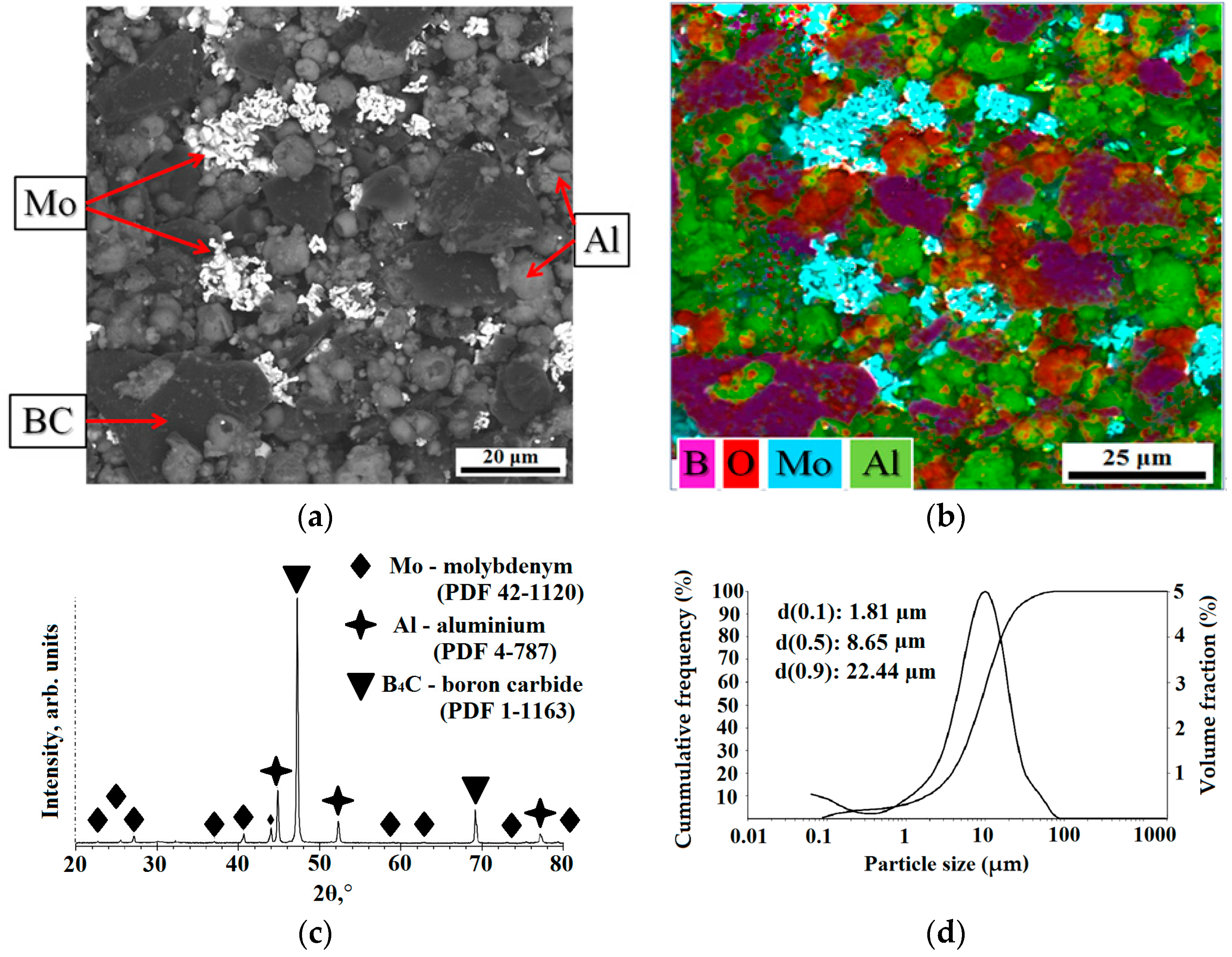
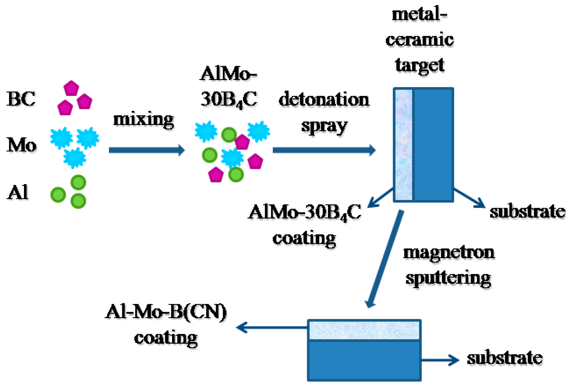
2.1. Powder Preparation

In this study, commercially available molybdenum (Mo, grade MPC, Plasmotherm, city, Russia), aluminum (Al grade AC, Plasmotherm, Moscow, Russia), and boron carbide (B4C F600 FEPA, 78B-20C, impurities 0.2B2O3-0.2Si-0.2Fe-1.0N-0.2C free, Volzhsky Abrasive Plant JSC, Zelenogorsk, Russia) powders were used as raw materials. The morphology and composition of the powder mixture, according to scanning electron microscopy (SEM, TESCAN MIRA 3 LMU, Brno, Czech Republic), are shown in Figure 1a,b.
The schematic of the preparation of AlMo-30B4C powder and coating, and Al-Mo-B(CN) coating is exhibited below in Figure 2.
The particle size distribution of the initial and mixed powders was measured via the laser scattering method using a particle size analyzer (Analysette 22 NanoTec Plus, Fritsch GmbH, Idar-Oberstein, Germany) (Figure 1d). The particle size distribution of powders is listed in Table 1.
The initial powders were mixed in a ratio of 30 wt% of Al, 40 wt% of Mo, and 30 wt% of B4C (denoted as AlMo-30B4C) in the Turbula mixer for 1 h and dried in an electric oven at 200 ± 5 °C for 60 min. The diffraction pattern of the AlMo-30B4C composite powder is displayed in Figure 1c. The diffraction pattern is consistent with Mo (PDF: 41-1120), confirming a cubic lattice structure; with Al (PDF 4-787), confirming a cubic lattice structure; and B4C (PDF 1-1163), confirming a rhombohedral lattice structure.

2.2. Metal–Ceramic Composite Target and AlMo-30B4C Coating Preparation

A copper cathode target of equipment for magnetron sputtering UNICOAT 200 (NPF “Elan-praktik”, Dzerzhinsk, Russia) in the form of a plate (198 mm × 78 mm × 4 mm) was made. A powder AlMo-30B4C was sprayed on the surface of cathode targets by a robotic complex for detonation spraying of coatings (IntelMashin LLC., Moscow, Russia) equipped with a multi-chamber detonation accelerator (MCDS) [41,42,43,44,45] (Figure 2). The parameters of the AlMo-30B4C coating spray are listed in Table 2. The structure and elemental composition of the AlMo-30B4C coating were studied using scanning electron microscopy (SEM, TESCAN MIRA 3 LMU, Brno-Kohoutovice, Czech Republic) (Figure 3).

2.3. Al-Mo-B(CN) Coating Preparation

The obtained cathode target with AlMo-30B4C coating was used to deposit the coating Al-Mo-B(CN) on flat specimens of steel AISI 316 (Fe–0.08C–0.75Si-2.0Mn–0.04P–0.03S–16.5Cr-11.0Ni-2.2Mo all in wt pct) (198 × 78 × 4 mm) and Si (100) (15 × 15 × 2 mm) using equipment for magnetron sputtering UNICOAT 200.
Preparation of the substrate surface: degreasing and cleaning with argon ions (10 min, P = 8 × 10⁻² Pa, and voltage 2.2 kV). Two targets were used as the sputtered material: a carbon target with a purity of 99.99% and a copper target with a metal–ceramic composite coating made of AlMo-30B4C.
AlMo-30B4C coating was applied using an external carbon target containing excess carbon to reduce oxygen in the coating. This can lead to the binding of oxygen in CO and minimization of its oxygen content in the coating [41].
The Al-Mo-B(CN) coating deposition was in the Direct Current mode (DC). The parameters of the spraying process are given in Table 3. The coating growth rate was 17 nm/min.

2.4. Coatings Characterization

Using scanning electron microscopy (SEM) and energy dispersive spectroscopy (EDS), the structure and elemental composition were studied using a scanning electron microscope (SEM, TESCAN MIRA 3 LMU, Brno-Kohoutovice, Czech Republic). The specimens were prepared via standard metallographic methods and cleaned with distilled water and dried at 100 °C for 3 h.
Porosity of the coating was determined through the metallographic method, using an optical inverted Olympus GX51 microscope (Olympus Corporation, Tokyo, Japan) and the “SIAMS Photolab” program [46].
Phase composition of the powder and coatings was determined using the X-ray phase analysis method (diffractometer ARL 9900 WS, Thermo Fisher Scientific, Basel, Switzerland) (Co-Kα, wavelength λ¼1.788996 Å, operating at 30 kV, 30 mA, and ICDDPDF-2 (2008) database).
The coating elemental concentrations and chemical states of each component were investigated using an X-ray photoelectron spectrometer PHI 5000 VersaProbe (ULVAC PHI, Chigasaki, Japan). Monochromatic Al-Kα X-rays (1486.6 eV) with a spot size of 200 μm were used to irradiate the sample surface. Photoelectron extraction angle was 45°. A pass energy of 23.5 eV with a step size of 0.05 eV was used to gather the high-resolution spectra. Exposure time was 50 ms/channel. MultiPak 9.0 software was used for peak fitting. Chemical bonds were determined by the magnitude of the chemical shifts in the partial spectra of selected elements using the “Curve Fitting” iterative selection procedure.
The topography of the Al-Mo-B(CN) coating was observed with a commercial scanning electron microscope Nanoeducator II (NT-MDT Spectrum Instruments, Moscow, Russia). All measurements were collected in contact mode. A silicon ceramic tip was used as a cantilever tip. The scanning area was 1000 nm. Arithmetic mean roughness (Ra) was obtained from AFM analyses.
The mechanical properties of the Al-Mo-B(CN) coating, i.e., hardness and Young’s modulus, were measured via the method of “instrumental indentation” (ISO 14577-1), using a Dynamic Ultra Micro Hardness Tester DUH-211S (Shimadzu, Kyoto, Japan) and following the method of Oliver and Pharr [47]. For each sample, 20 indentations were carried out (indenter load—53 mN, max. depth of penetration—0.25 μm). Tests were performed on the Al-Mo-B(CN) coating on a silicon substrate to ensure the accuracy of the experimental results.
To determine the adhesion strength of the coatings, the scratch tester MFT-2000A (Rtec Instruments, San Jose, CA, USA) with Rockwell C indenter (radius of 200 μm) was used. A progressive load of 0.9 N (initial) and 40 N (final), a scratch speed of 3.5 mm/min, and a scratch length of 10 mm were used. The critical loads Lc were used to assess the adhesion strength of the coating/substrate.
Ball sliding tests on a plane under dry conditions (25 °C, relative humidity 50%) were carried out using a tribometer MFT-2000A (Rtec Instruments, USA) according to ASTM G-99 [48]. All tests were performed using an uncoated Ø = 10 mm diameter 100Cr6 ball (ISO 683-17:2014, hardness 19 GPa). Specimens were tested under a 1 N normal load, with a 120 r/min sliding speed, a total sliding time of 30 min, and a radius of 8 mm. Analyses of topography, chemical composition, and distribution of elements inside the wear tracks were conducted after tribological testing by means of scanning electron microscopy and an energy dispersive X-ray spectroscopy (EDS) system (SEM, TESCAN MIRA 3 LMU, Brno-Kohoutovice, Czech Republic).

3. Results

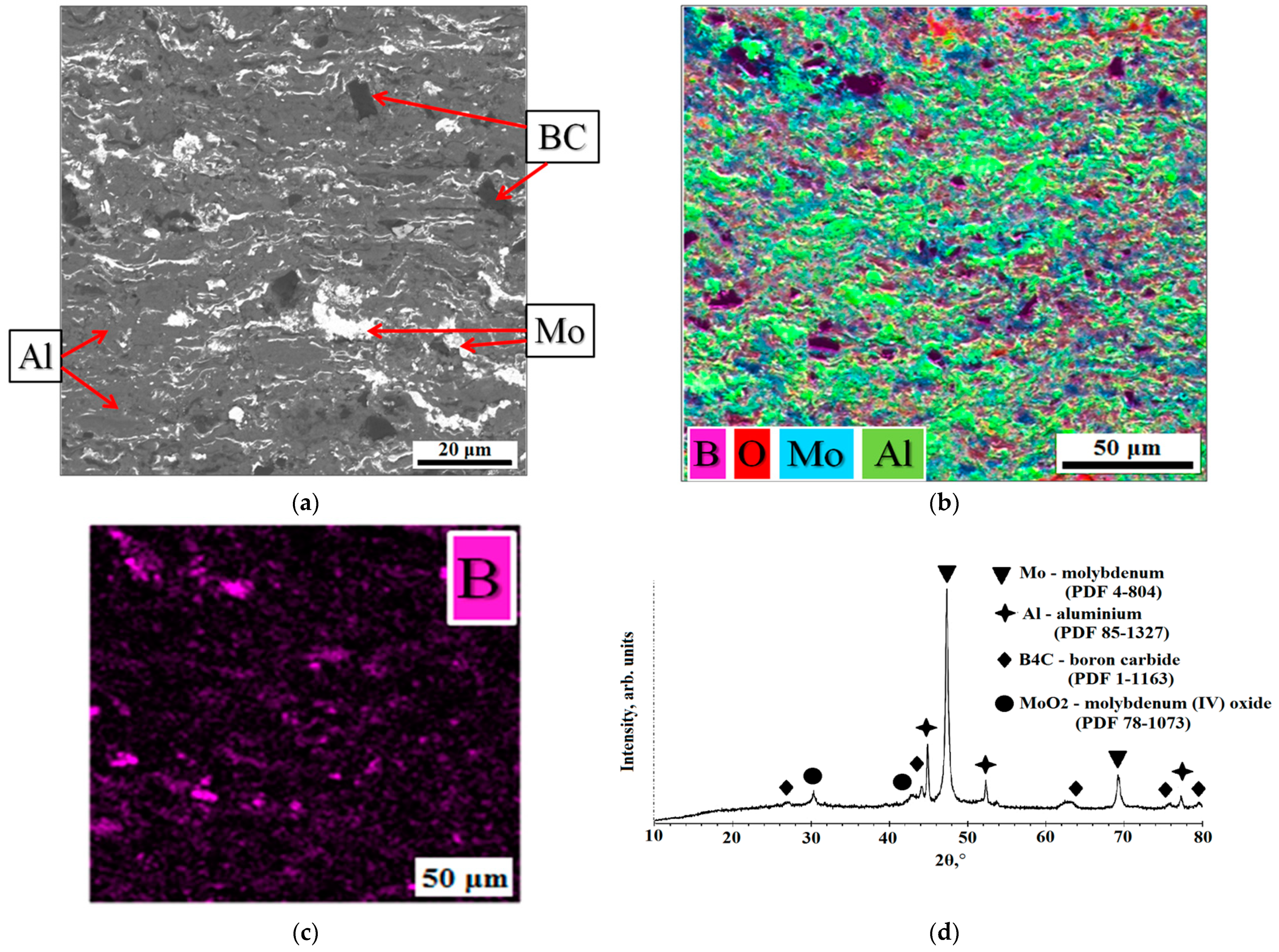
3.1. AlMo-30B4C Coating: Structure and Phase Composition

Figure 3 shows the cross-sectional SEM images and X-ray diffraction pattern of the AlMo-30B4C coating on the surface of the target for magnetron sputtering. The coatings have thicknesses of about 350–400 µm. The AlMo-30B4C coating has a dense and defect-free lamella-type structure with a low porosity of less than 1%. Mo and Al particles melted and spread, but B4C particles were not destroyed and were distributed throughout the entire depth of the coating (Figure 3b,c).
An analysis of the cross section of the AlMo-30B4C coating (Figure 3a,b) showed the presence of B, C, Mo, and Al in the volume of the coating. The elemental composition of the cross-sectional surface of the AlMo-30B4C coating is shown in Table 4.
X-ray diffraction analysis of the AlMo-30B4C coating is given in Figure 3d. It has been established that the following phases are present in the coatings: Mo (PDF: 4-804), confirming a cubic lattice structure; Al (PDF: 85-1327), confirming a cubic lattice structure; B4C (PDF: 1-1163), confirming a rhombohedral lattice structure; all of which were also present in the feedstock powder, as well as a small amount of metal oxide phase–MoO2 phase (PDF: 78-1073), confirming a monoclinic lattice structure. This is explained by the fact that the sprayed particles are not subject to strong oxidation during deposition. It is especially important to note that the use of the detonation spray method allows for a high rate of deposition of powder particles, which reduces the time during which the particles are in flight during the coating application. This can reduce the likelihood of unwanted chemical reactions during the deposition process and improve the quality of the target coating.

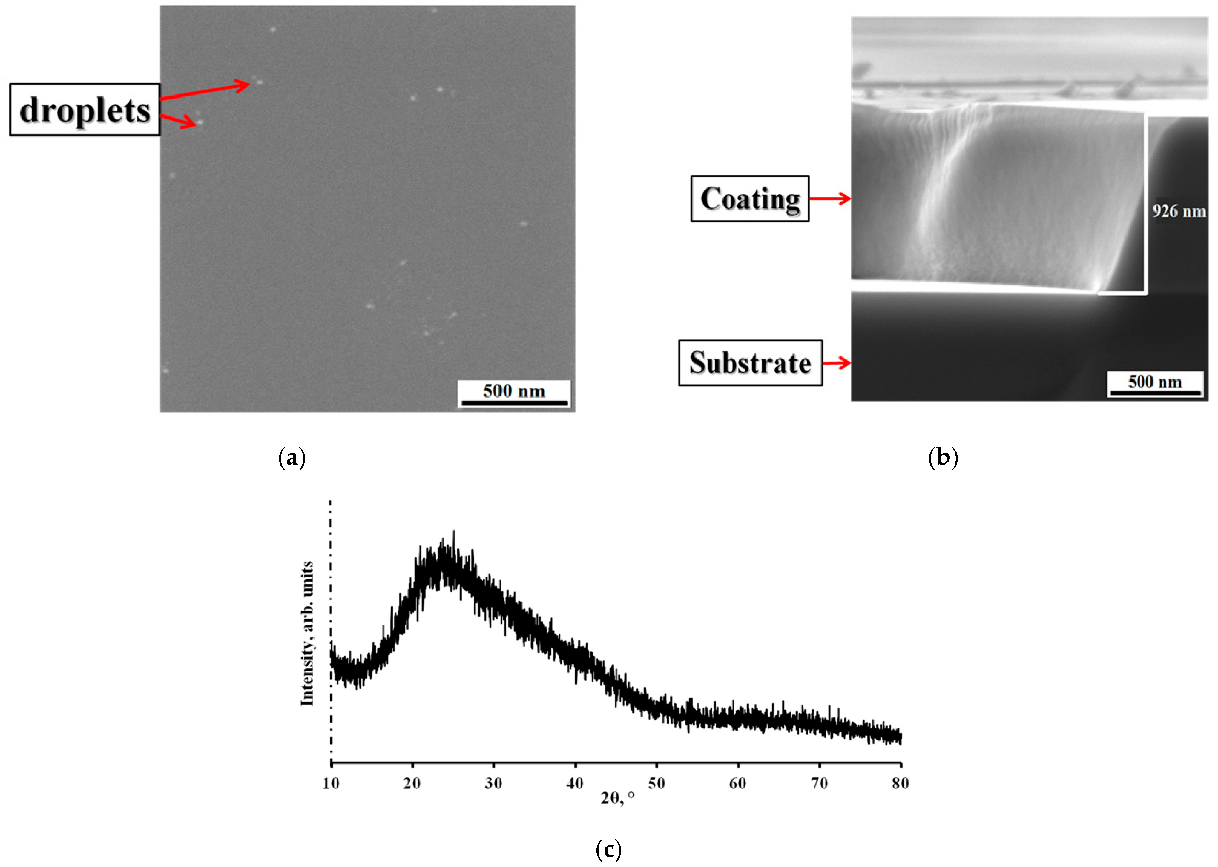
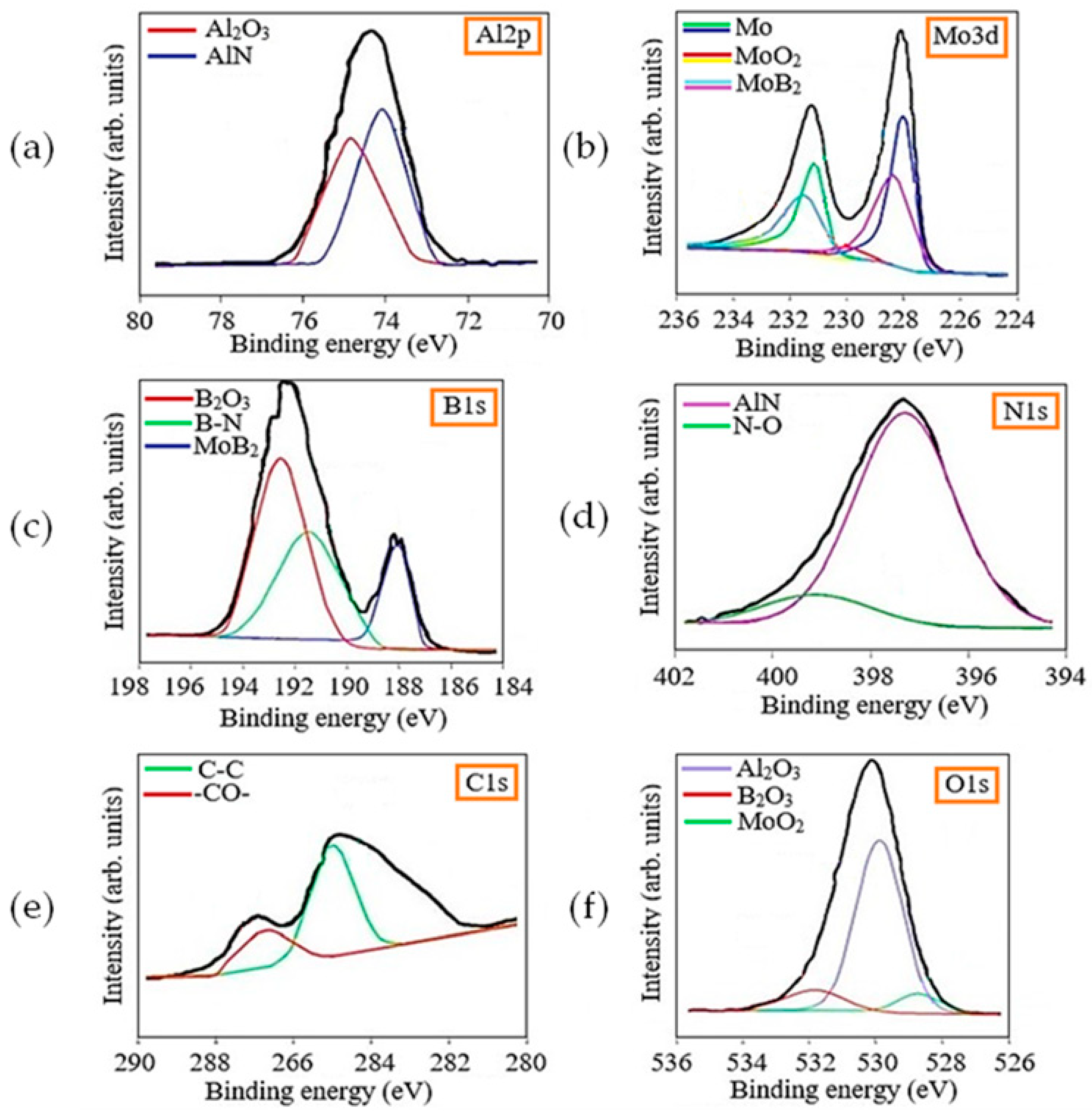
3.2. Al-Mo-B(CN) Coating: Structure, Elemental (Concentrations, Chemical States), and Phase Composition

The SEM top-view image, which can be seen in Figure 4a, confirms the formation of a smooth Al-Mo-B(CN) coating with slight roughness and a few scattered droplets.
Figure 4b shows a characteristic image of cross-section fractures in the coating deposited onto a monocrystalline silicon substrate. It can be seen that the coating (thickness ~1 μm) is characterized by a dense homogeneity with a structure featuring small drip inclusions but without the columnar elements usually observed in Me-B (C or N) coatings [15,49,50,51]. Due to the columnar structure of coatings, mechanical properties deteriorate due to the diffusion of oxygen from the surface into the depth of the material along the boundaries of columnar grains [1,52,53,54]. The Al-Mo-B(CN) coating has a structure without typical growth defects (nodal, point, cone-shaped, and open voids) associated with the magnetron sputtering process [55]. A similar structure without any peculiarities was observed in the Mo-Si-B-(N) [1] and MoB(C) coatings [17].
The results of the X-ray diffraction analysis (XRD) of the Al-Mo-B(CN) coatings are given in Figure 4c. A single broad peak dominates the pattern. A broad peak indicates an amorphous microstructure with a short-range order, or the presence of crystallites smaller than 2 nm, which is confirmed by the previous results of other researchers [41,55,56].
The surface of the Al-Mo-B(CN) coating was analyzed by XPS in order to understand the chemical bonding state of the surface. The Al2p, Mo 3d, B1s, N1s, C1s, and O1s XPS core level spectra of the Al-Mo-B(CN) coatings are presented in Figure 5 to illustrate the chemical binding states of these elements near the surface region.
The presence of oxides in the coating is due to the presence of oxide compounds on the surface of the metal–ceramic target. Carbon bonds were detected: a peak at 284.8 eV (CC sp2 bond), and a peak at 288.0 eV (-CO- bond). As observed in other works [57,58], the presence of free carbon phases in the coating was recorded. The Mo 3d 5/2 peak centered at 227.8 eV and the Mo 3d 3/2 peak centered at 231.0 eV correspond to metallic Mo. The Mo 3d 5/2 peak at 230 eV and 233 eV corresponds to MoO2, and the Mo 3d5/2 peak at 229 eV and 231.5 eV corresponds to MoB2. The Al 2p spectra were separated into a higher intensity Al 2p3/2 peak located at 74.4 eV and a lower intensity Al 2p1/2 peak located at 75.9 eV, corresponding to Al–N and the Al-O chemical bond [59,60], respectively.
The Al-O bond may indicate the presence of oxygen in the form of amorphous Al2O3. The N 1s ground level spectrum was deconvolved into two peaks. The peak at 397.3 eV corresponds to the Al-N bond, which proves the formation of AlN. The peak at 399.1 eV matched well with the N-O bond that formed the Al-O-N system, an aluminum oxynitride phase. The O 1s core level spectrum consists of a peak at 531.1 eV and was assigned to the Al-O bond of amorphous Al2O3, which is consistent with the Al 2p1/2 peaks. XPS analysis confirmed the formation of the MoB2 and AlN phase with an admixture of oxygen in the form of aluminum oxide, molybdenum oxide, and boron oxide.
The geometrical structure of the Al-Mo-B(CN) coating was examined using an atomic force microscope (AFM). During measurement, an area of 1000 × 1000 nm was scanned (Figure 6). The Al-Mo-B(CN) coating had a homogeneous surface with low roughness Ra of 2.2 nm. The low roughness of the coatings in the Me-B(CN) system was also noted earlier in [9,61,62,63].
The surface of the Al-Mo-B(CN) coating was smooth and characterized by a granular surface morphology (Figure 6), which indicates a fine nano-sized grain structure resulting from the continuous formation of nuclei during the growth of the coating [64]. Differences in the height and density of the protrusions indicate that the structure of the coating is polymorphic.

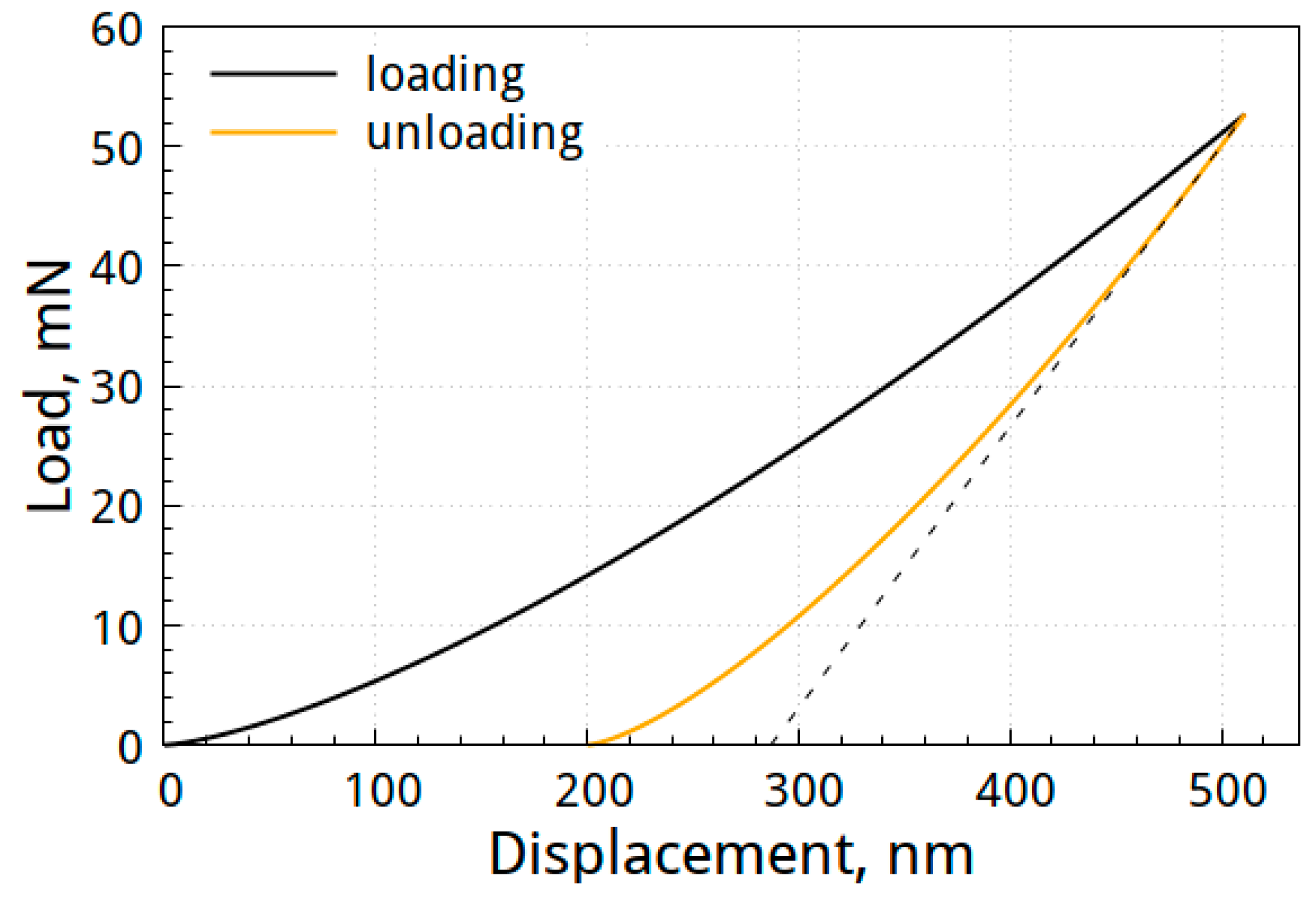
3.3. Mechanical Properties of Al-Mo-B(CN) Coating

Mechanical properties of the Al-Mo-B(CN) coating, such as hardness (H), elastic modulus (E), elastic recovery (W), plasticity index (H/E), and plastic deformation resistance (H3/E2), are presented in Table 5. Figure 7 shows the load–displacement curve of the specimen deposited with the Al-Mo-B(CN) coating.
The hardness of the coatings was 13.0 ± 3.6 GPa, the elastic modulus was 114 ± 5.8 GPa, and the elastic recovery was 45%. We should note that the mechanical properties of the obtained Al-Mo-B(CN) coating are consistent with those previously reported in [65,66,67,68].
Using nanoindentation data, the parameters H/E and H3/E2 were calculated (Table 4), which, as was shown earlier [69,70], in a number of cases can serve as criteria for the wear resistance of coatings. The Al-Mo-B(CN) coating has high values of H/E = 0.11 and H3/E2 = 0.17 GPa.
For adhesive strength definition, the method of scratch testing was used (Figure 8). The adhesive strength was indicated by critical loads Lc [71].
At a relatively low applied load (Lc1), there were no chips and only a small number of cracks were observed. Also, the failure of the coating at Lc1 corresponds to the cohesive failure of the coating [72]. Critical loads during the scratch testing of the coating were determined by changes in the friction force and the image of the scratches.
The values of Lc1, Lc2, and Lc3 were reflected in the CoF values (Figure 8). At the beginning, CoF increased from 0 to ~0.1 due to the increase in the contact area. Thereafter, CoF gradually increased with increasing applied load until Lc1 (CoF ~0.15). Afterwards, CoF remained stable until the end of the test (Figure 8).
For the Al-Mo-B(CN) coating, the initial cracking first occurred at Lc1 ~4 N (Figure 8). With an increased applied load (Lc2, 8 N), cracking first within the scratched track and then local spalling at the edge of the track started to occur. With an increasing load, the substrate is deformed and the tensile cracks become more severe on the coating’s surface, which can progress to chipping of the coating due to the cohesive failure when the load exceeds the Lc3 (11 N, cohesive failure) (Figure 8).
In the next step, tribological analyses were conducted on the Al-Mo-B(CN) coating. Figure 9 exhibits the friction coefficient curve of the Al-Mo-B(CN) coating against a steel 100Cr6 counterpart.
The curve shows a running-in period that extends over about 450 s. The initial COF was 0.12, then a high and varying COF of 0.70 to 0.87 was found. After that initial period, a drop of COF towards a lower, basically constant COF of 0.75 to 0.80 was found. The average COF of the Al-Mo-B(CN) coating was 0.77.
A detailed look into the wear scar was conducted (Figure 10a,b). The surface of the wear track was found to be smooth, and had some delamination and fatigue cracks, and the edges of the track accumulated some wear residue (Figure 10a). These are typical signs of fatigue and abrasive wear [73,74]. As can be seen in Figure 10b, the surface of the wear scar is partially covered with an oxide-based tribofilm. Elemental distribution maps show a high concentration of iron within the track, which forms a layer parallel to the wear direction. Thus, we can say that the counterbody material oxidizes during wear, accumulates in the track, and forms a discontinuous layer. The segregation of wear particles on the surface of the counterbody along the edges of the tribocontact area was recorded (Figure 10c). The layer of stuck wear products contained elements of both the coating and the counterpart material.

4. Conclusions

The composite metal–ceramic Al-Mo-B4C target manufactured by a robotic complex for the detonation spraying of coatings, as well as the chemical composition, and the microstructure and properties of the thin Al-Mo-B(CN) coating synthesized via magnetron sputter deposition using this target have been investigated within this work.
The main results can be summarized as follows:
  • A copper cathode target with AlMo-30B4C equipment coating for magnetron sputtering UNICOAT 200 (Russia) in the form of a plate (198 × 78 × 4 mm) was made. AlMo-30B4C coating (thickness ~350–400 µm) was fabricated by a robotic complex for detonation spraying.
  • AlMo-30B4C coating has a dense and defect-free lamella-type structure with low porosity of less than 1%. The AlMo-30B4C coating consisted of the Mo, Al, and B4C phases, and a small amount of metal oxide phase–MoO2 phase.
  • The obtained composite metal–ceramic Al-Mo-B4C target was used to deposit the Al-Mo-B(CN) coating (DC mode) on flat specimens of AISI 316 steel and silicon using equipment for magnetron sputtering UNICOAT 200.
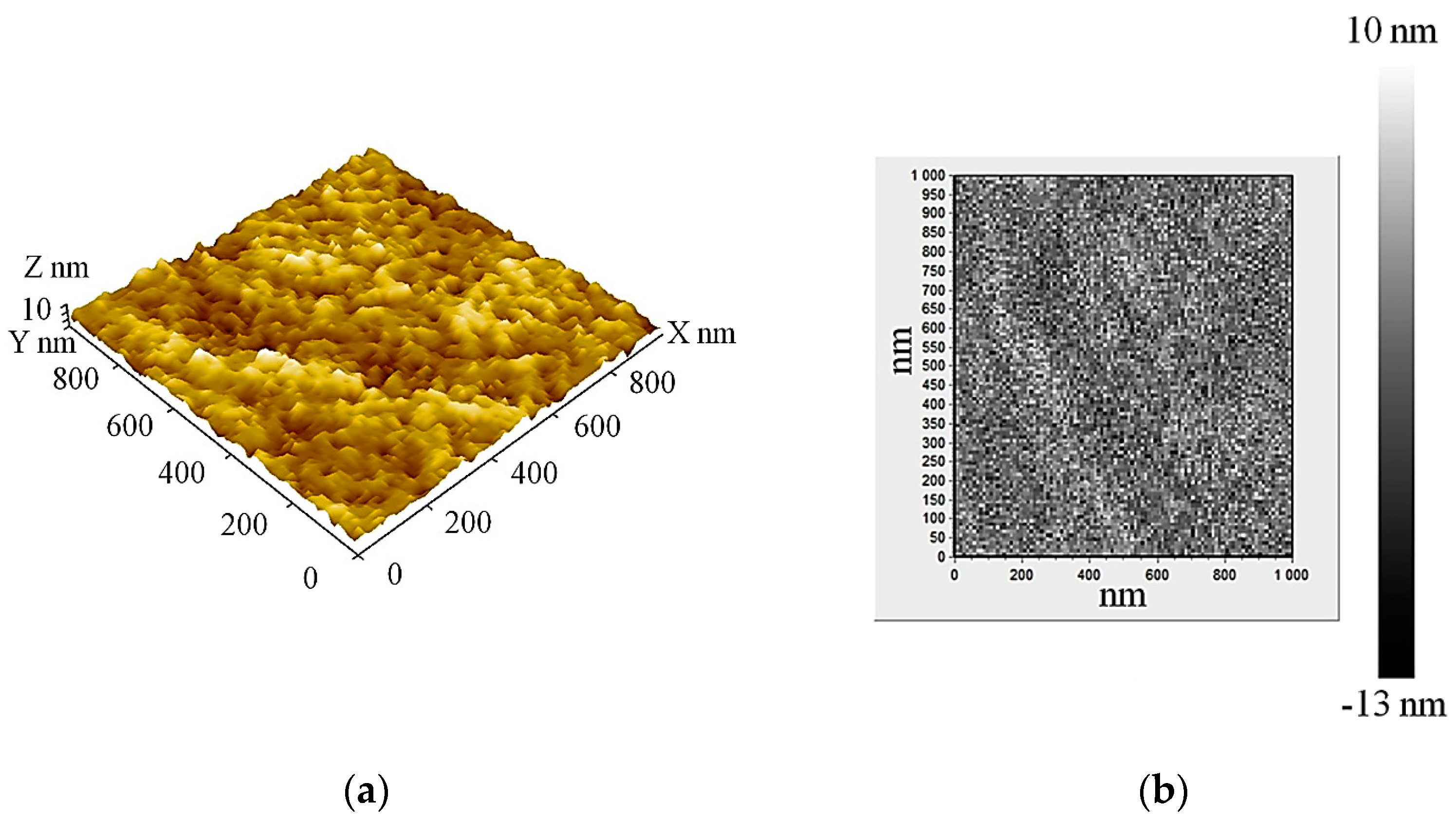
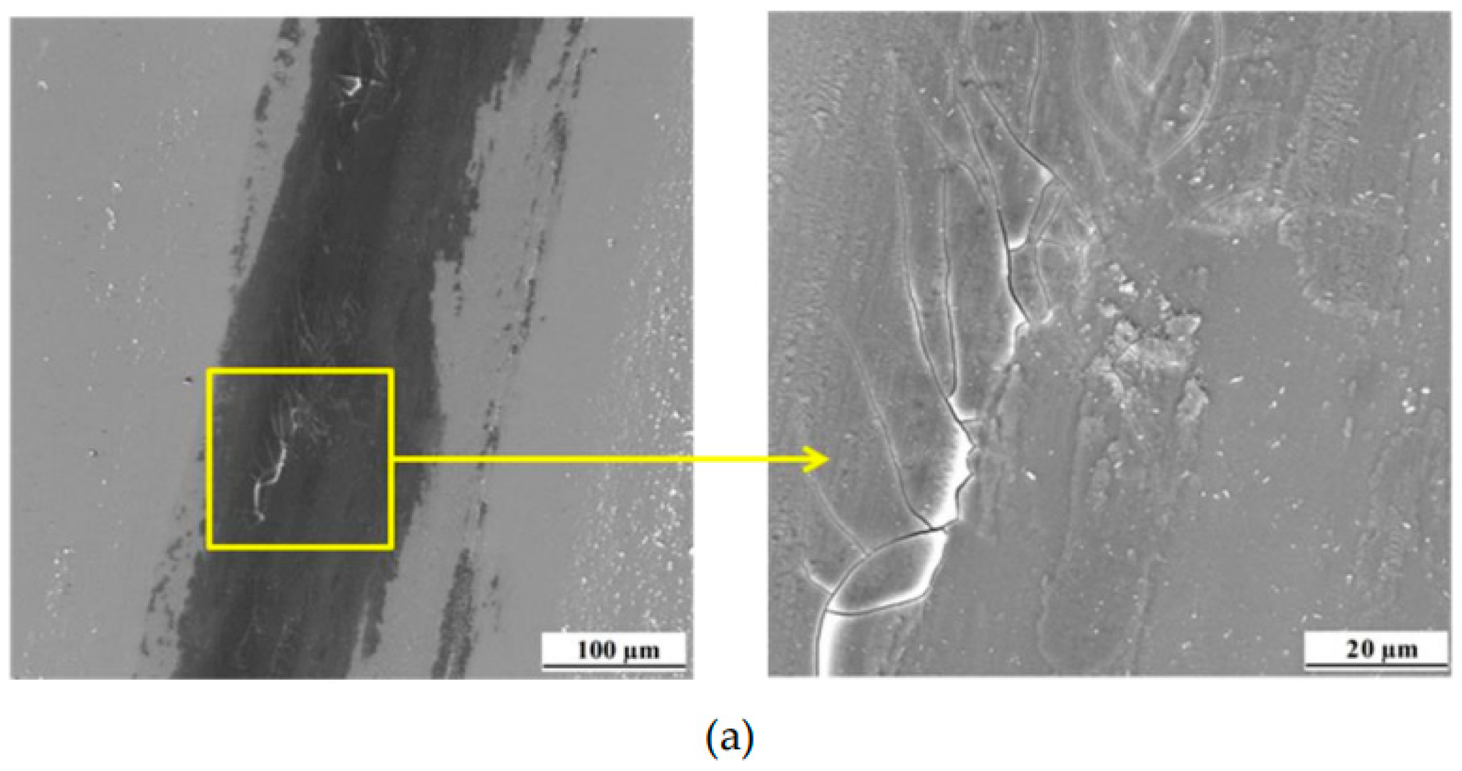
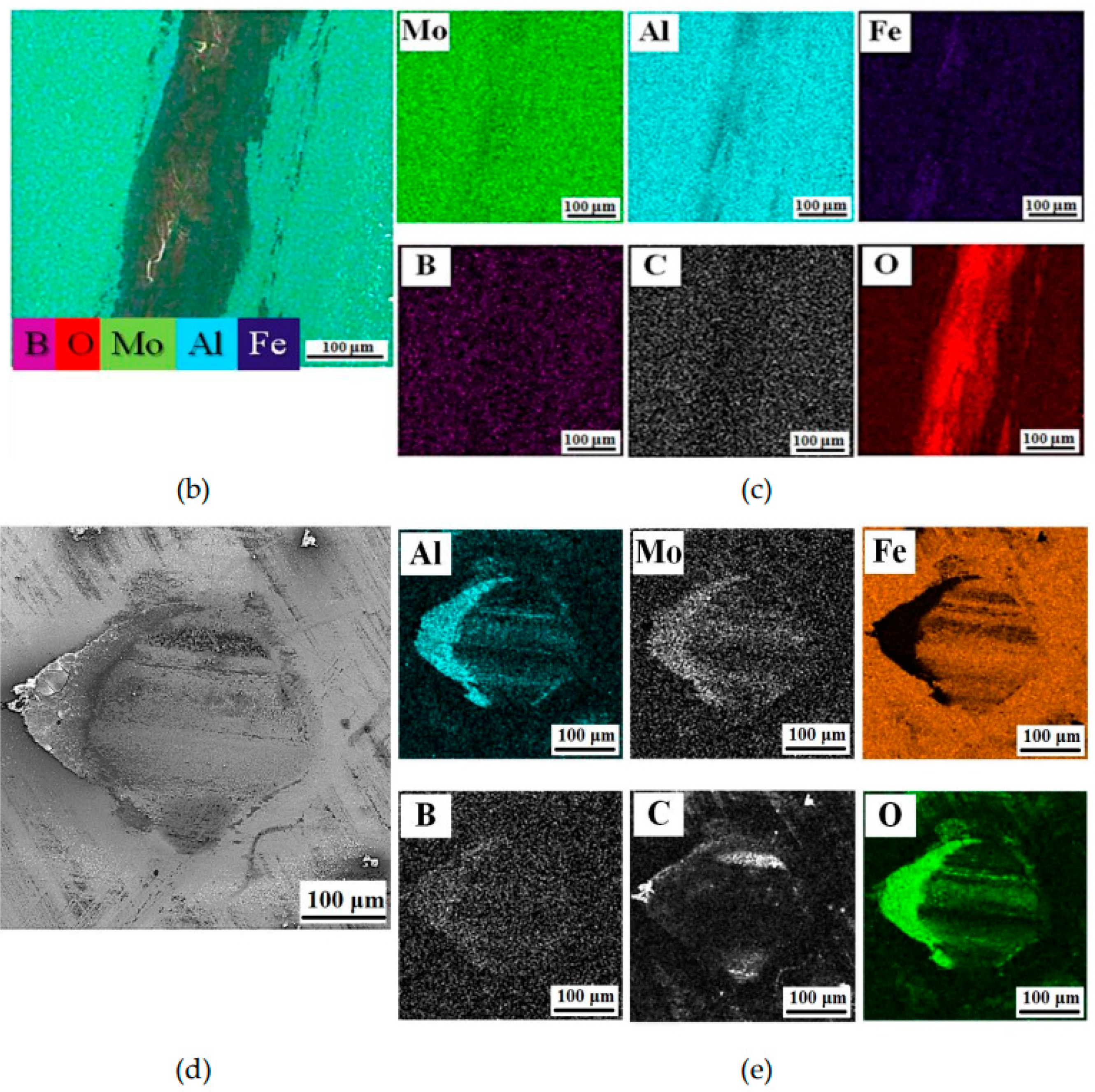
  • A smooth Al-Mo-B(CN) coating (thickness ~1 μm) with little roughness (Ra 2.2 nm) and a small number of scattered droplets was formed. Al-Mo-B(CN) coating has dense homogeneity with a structure featuring small drip inclusions but with no columnar elements, and without the typical growth defects (nodal, point, cone-shaped, and open voids) associated with magnetron sputtering.
  • Al-Mo-B(CN) coating has an amorphous structure. XPS analysis confirmed the formation of the MoB2 and AlN phase with an admixture of oxygen in the form of aluminum oxide, molybdenum oxide, and boron oxide.
  • The hardness of the Al-Mo-B(CN) coating was 13.0 ± 3.6 GPa, the elastic modulus was 114 ± 5.8 GPa, and the elastic recovery was 45%, H/E—0.11, and H3/E2 = 0.17 GPa.
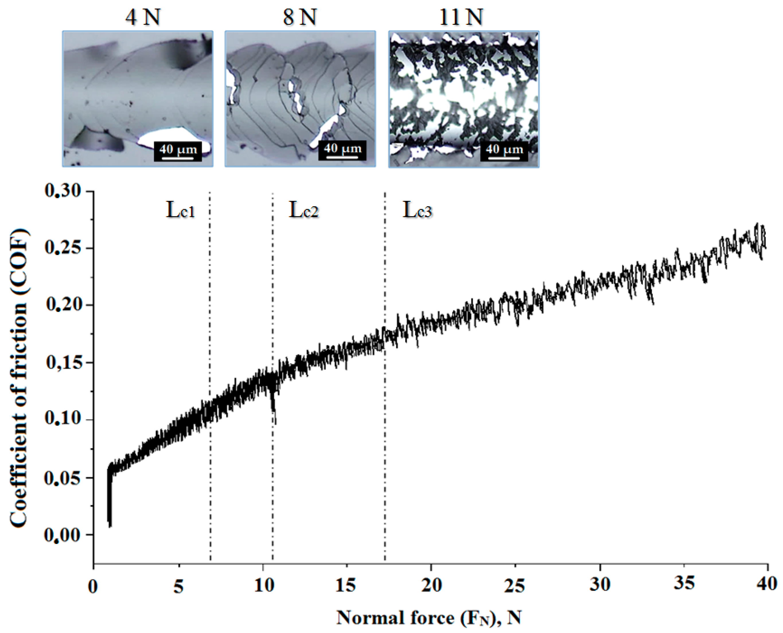
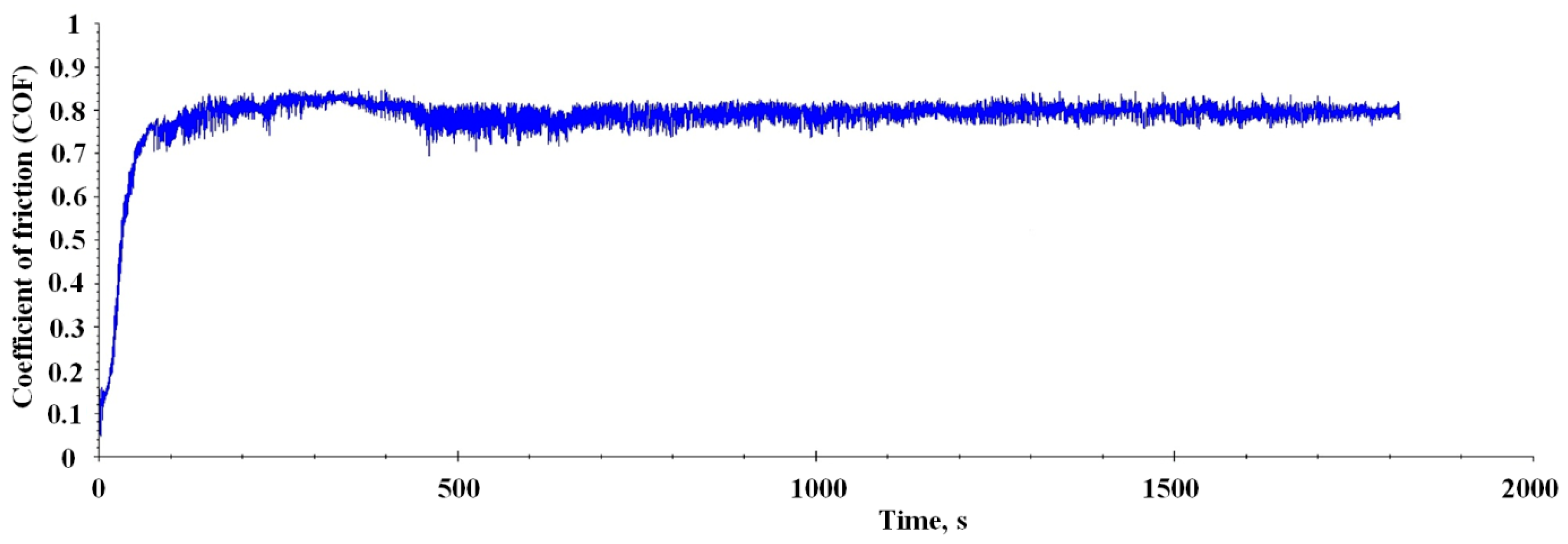
  • Al-Mo-B(CN) coating has a friction coefficient of 0.8 against a steel 100 Cr6 ball, and the failure mode was fatigued and abrasive. The adhesion strength of Al-Mo-B(CN) coating amounted to about 11 N, and the failure mode was cohesive.

Author Contributions

Conceptualization, V.S.; data curation, S.V.Z. and D.P.; formal analysis, M.L. and A.S.; investigation, M.K., S.V.Z. and M.L.; methodology, D.P., M.L. and M.K.; writing—original draft, V.S. and M.K. All authors have read and agreed to the published version of the manuscript.

Funding

This research was funded by the Russian Science Foundation under grant no. 21-19-00536. The studies were carried out with equipment from the Centre for High Technologies of BSTU using the unique scientific installation no. 3552744, and the Joint Research Center of Belgorod State National Research University «Technology and Materials».

Institutional Review Board Statement

Not applicable.

Informed Consent Statement

Not applicable.

Data Availability Statement

Data are contained within the article.

Conflicts of Interest

The authors declare no conflict of interest.

References

  1. Kiryukhantsev-Korneev, P.V.; Bondarev, A.V.; Shtansky, D.V.; Levashov, E.A. Structure and properties of nanocomposite Mo-Si-B-(N) coatings. Prot. Met. Phys. Chem. Surf. 2015, 51, 794–802. [Google Scholar] [CrossRef]
  2. Kosminska, Y.O.; Kornyushchenko, G.S.; Gannych, Y.V.; Perekrestov, V.I. Fabrication and physical properties of coatings belonging to W, Ta, Hf, Ti, Mo, Cr, Al and C based multicomponent systems. J. Superhard Mater. 2020, 42, 388–395. [Google Scholar] [CrossRef]
  3. Sheu, H.H.; Tzeng, Y.C.; Syu, J.H. Study of the strengthening mechanism of electrodeposited Ni-B thin films with ultra-low boron content. Mater. Lett. 2019, 238, 275–277. [Google Scholar] [CrossRef]
  4. Yildiz, R.A.; Genel, K.; Gulmez, T. Effect of electroless Ni-B and Ni-WB coatings on the corrosion-fatigue behavior of 7075 Al alloy. Int. J. Fatigue 2021, 144, 106040. [Google Scholar] [CrossRef]
  5. Kiryukhantsev-Korneev, P.V.; Sytchenko, A.D.; Gorshkov, V.A.; Loginov, P.A.; Sheveyko, A.N.; Nozhkina, A.V.; Levashov, E.A. Complex study of protective Cr3C2–NiAl coatings deposited by vacuum electro-spark alloying, pulsed cathodic arc evaporation, magnetron sputtering, and hybrid technology. Ceram. Int. 2022, 48, 10921–10931. [Google Scholar] [CrossRef]
  6. Zhang, Y.; Zhang, S.; He, Y.; Li, H.; He, T.; Fan, Y.; Zhang, H. Mechanical properties and corrosion resistance of pulse electrodeposited Ni-B/B4C composite coatings. Surf. Coat. Technol. 2021, 421, 127458. [Google Scholar] [CrossRef]
  7. Ivanovskii, A.L. Mechanical and electronic properties of diborides of transition 3d–5d metals from first principles: Toward search of novel ultra-incompressible and superhard materials. Prog. Mater. Sci. 2012, 57, 184–228. [Google Scholar] [CrossRef]
  8. Mitterer, C. Borides in thin film technology. J. Solid State Chem. 1997, 133, 279–291. [Google Scholar] [CrossRef]
  9. Kuznetsova, T.; Zubar, T.; Chizhik, S.; Gilewicz, A.; Lupicka, O.; Warcholinski, B. Surface microstructure of Mo(C)N coatings investigated by AFM. J. Mater. Eng. Perform. 2016, 25, 5450–5459. [Google Scholar] [CrossRef]
  10. Nedfors, N.; Primetzhofer, D.; Wang, L.; Lu, J.; Hultman, L.; Jansson, U. Characterization of magnetron sputtered Cr-B and Cr-B-C thin films for electrical contact applications. Surf. Coat. Technol. 2015, 266, 167–176. [Google Scholar] [CrossRef]
  11. Ok, J.-T.; Park, I.-W.; Moore, J.J.; Kang, M.C.; Kim, K.H. Syntheses and mechanical properties of Ti-B-C coatings by a plasma-enhanced chemical vapor deposition. Surf. Coat. Technol. 2005, 200, 1418–1423. [Google Scholar] [CrossRef]
  12. Stüber, M.; Schier, V.; Holleck, H. Properties and performance of new metastable Ti-BC-N hard coatings prepared by magnetron sputtering. Surf. Coat. Technol. 1995, 74–75, 833–837. [Google Scholar] [CrossRef]
  13. Mallia, B.; Stüber, M.; Dearnley, P.A. Character and chemical-wear response of high alloy austenitic stainless steel (Ortron 90) surface engineered with magnetron sputtered Cr-B-N ternary alloy coatings. Thin Solid Films 2013, 549, 216–223. [Google Scholar] [CrossRef]
  14. Yang, J.F.; Yuan, Z.G.; Liu, Q.; Wang, X.P.; Fang, Q.F. Characterization of Mo-Al-N nanocrystalline films synthesized by reactive magnetron sputtering. Mater. Res. Bull. 2009, 44, 86–90. [Google Scholar] [CrossRef]
  15. Jung, H.S.; Qi, M.W.; Kwang, H.K.; Shin, J.H. Microstructural evolution and tribological behavior of Mo-Cu-N coatings as a function of Cu content. Mater. Chem. Phys. 2011, 130, 870–879. [Google Scholar] [CrossRef]
  16. Zhao, Y.; Kamiya, K.; Hashimoto, K.; Nakanishi, S. In Situ CO2-emission assisted synthesis of molybdenum carbonitride nanomaterial as hydrogen evolution electrocatalyst. J. Am. Chem. Soc. 2015, 137, 110–113. [Google Scholar] [CrossRef] [PubMed]
  17. Malinovskis, P.; Palisaitis, J.; Persson, P.O.Å.; Jansson, U.; Lewin, E. Synthesis and characterization of Mo-B-C thin films deposited by non-reactive DC magnetron sputtering. Surf. Coat. Technol. 2017, 309, 506–515. [Google Scholar] [CrossRef]
  18. Totemeier, T.C.; Wright, R.N.; Swank, W.D. FeAl and Mo–Si–B intermetallic coatings prepared by thermal spraying. Intermetallics 2004, 12, 1335–1344. [Google Scholar] [CrossRef]
  19. Wang, Y.; Wang, D.; Yan, J. Preparation and characterization of MoSi2/MoB composite coating on Mo substrate. J. Alloys Compd. 2014, 589, 384–388. [Google Scholar] [CrossRef]
  20. Warcholinski, B.; Gilewicz, A.; Kuznetsova, T.A.; Zubar, T.I.; Chizhik, S.A.; Abetkovskaia, S.O.; Lapitskaya, V.A. Mechanical properties of Mo(C)N coatings deposited using cathodic arc evaporation. Surf. Coat. Technol. 2017, 319, 117–128. [Google Scholar] [CrossRef]
  21. Kudryashov, A.E.; Lebedev, D.N.; Potanin, A.Y.; Levashov, E.A. Structure and properties of coatings produced by pulsed electrospark deposition on nickel alloy using Mo-Si-B electrodes. Surf. Coat. Technol. 2018, 335, 104–117. [Google Scholar] [CrossRef]
  22. Kiryukhantsev-Korneev, P.V.; Kudryashov, A.E.; Levashov, E.A. Recent achievements on oxidation-resistant Cr-(Al)-Si-B, Mo-(Al)-Si-B, Zr-(Al)-Si-B coatings obtained by magnetron sputtering and pulsed electrospark deposition (part 2). Galvanotechnik 2018, 109, 1044–1050. [Google Scholar]
  23. Wen, S.H.; Zhou, C.G.; Sha, J.B. Microstructural evolution and oxidation behaviour of Mo-Si-B coatings on an Nb-16Si-22Ti-7Cr-2Al-2Hf alloy at 1250 °C prepared by spark plasma sintering. Surf. Coat. Technol. 2018, 352, 320–329. [Google Scholar] [CrossRef]
  24. Zhu, L.; Zhu, Y.; Ren, X.; Zhang, P.; Qiao, J.; Feng, P. Microstructure, properties and oxidation behavior of MoSi2-MoB-ZrO2 coating for Mo substrate using spark plasma sintering. Surf. Coat. Technol. 2019, 375, 773–781. [Google Scholar] [CrossRef]
  25. Buršík, J.; Buršíková, V.; Souček, P.; Zábranský, L.; Vašina, P. Nanostructured Mo-B-C coatings. Rom. Rep. Phys. 2016, 68, 1069–1075. [Google Scholar]
  26. Zábranský, L.; Buršíková, V.; Souček, P.; Vašina, P.; Buršík, J. On the study of the mechanical properties of Mo-B-C coatings. Eur. Phys. J. Appl. Phys. 2016, 75, 24716/1–24716/7. [Google Scholar] [CrossRef]
  27. Buršíková, V.; Sobota, J.; Grossman, J.; Fořt, T.; Dupák, L.; Zábranský, L.; Souček, P.; Vašina, P.; Buršík, J. Study of fracture resistance of nanolaminate coatings using indentation and impact tests. Solid State Phenom. 2017, 258, 318–321. [Google Scholar] [CrossRef]
  28. Kiryukhantsev-Korneev, P.V.; Sytchenko, A.D.; Potanin, A.Y.; Vorotilo, S.A.; Levashov, E.A. Mechanical properties and oxidation resistance of Mo-Si-B and Mo-Hf-Si-B coatings obtained by magnetron sputtering in DC and pulsed DC modes. Surf. Coat. Technol. 2020, 403, 126373. [Google Scholar] [CrossRef]
  29. Sanchette, F.; Billard, A. Special Issue “Magnetron Sputtering Deposited Thin Films and Its Applications”. Coatings 2020, 10, 1072. [Google Scholar] [CrossRef]
  30. Kiryukhantsev-Korneev, F.V.; Sheveiko, A.N.; Komarov, V.A.; Blanter, M.S.; Skryleva, E.A.; Shirmanov, N.A.; Levashov, E.A.; Shtansky, D.V. Nanostructured Ti-Cr-B-N and Ti-Cr-Si-C- N coatings for hard-alloy cutting tools. Russ. J. Non-Ferrous Metals. 2011, 52, 311–318. [Google Scholar] [CrossRef]
  31. Shtansky, D.V.; Kiryukhantsev-Korneev, P.V.; Sheveyko, A.N.; Mavrin, B.N.; Rojas, T.C.; Fernandez, A.; Levashov, E.A. Comparative investigation of TiAlC(N), TiCrAlC(N), and CrAlC(N) coatings deposited by sputtering of MAX- phase Ti2−xCrxAlC targets. Surf. Coat. Technol. 2009, 203, 3595–3609. [Google Scholar] [CrossRef]
  32. Kiryukhantsev-Korneev, P.V.; Pierson, J.F.; Kuptsov, K.A.; Shtansky, D.V. Hard Cr–Al–Si–B–(N) coatings deposited by reactive and non-reactive magnetron sputtering of CrAlSiB target. Appl. Surf. Sci. 2014, 314, 104–111. [Google Scholar] [CrossRef]
  33. Kiryukhantsev-Korneev, P.V. Pulsed magnetron sputtering of ceramic SHS targets as a promising technique for deposition of multifunctional coatings. Prot. Met. Phys. Chem. Surf. 2020, 56, 343–357. [Google Scholar] [CrossRef]
  34. Bolotskaia, A.; Avdeeva, V.; Bazhin, P.; Mikheev, M.; Stolin, A.; Novikov, V.; Kovaleva, M.; Sirota, V. Coatings prepared by electro-spark alloying with SHS electrode materials based on Ti-B-Fe-AlN. Coatings 2023, 13, 1264. [Google Scholar] [CrossRef]
  35. Fedotov, A.F.; Amosov, A.P.; Ermoshkin, A.A.; Lavro, V.N.; Altukhov, S.I.; Latukhin, E.I.; Davydov, D.M. Composition, structure, and properties of SHS-compacted cathodes of the Ti-C-Al-Si system and vacuum-arc coatings obtained from them. Russ. J. Non-Ferrous Metals 2014, 55, 477–484. [Google Scholar] [CrossRef]
  36. Potanin, A.Y.; Kiryukhantsev-Korneev, P.V.; Rupasov, S.I.; Pogozhev, Y.S.; Levashov, E.A. Application of SHS for production of composite ceramic cathodes for PVD of high-temperature protective Mo-(Hf/Zr)-Si-B coatings. In Proceedings of the International Symposium on Self-Propagating High-Temperature Synthesis, Moscow, Russia, 16–20 September; pp. 357–358.
  37. Kunc, F.; Musil, J.; Mayrhofer, P.H.; Mitterer, C. Low-stress superhard Ti-B films prepared by magnetron sputtering. Surf. Coat. Technol. 2003, 174, 744–753. [Google Scholar] [CrossRef]
  38. Mraz, S.; Emmerlich, J.; Weyand, F.; Schneider, J.M. Angle-resolved evolution of the composition of Cr-Al-C thin films deposited by sputtering of a compound target. J. Phys. D 2013, 46, 135501. [Google Scholar] [CrossRef]
  39. Vasyliev, V.V.; Luchaninov, A.A.; Reshetnyak, E.N.; Strel’nitskij, V.E.; Tolmacheva, G.N.; Pribytkov, G.A.; Gurskikh, A.V.; Krinitcyn, M.G. Application of powder cathodes for Ti-Si-N coatings deposition from the filtered vacuum-arc plasma. Int. J. Surf. Sci. Eng. 2015, 13, 148–163. (In Russian) [Google Scholar]
  40. Rueß, H.; to Baben, M.; Mráz, S.; Shang, L.; Polcik, P.; Kolozsvári, S.; Hans, M.; Primetzhofer, D.; Schneider, J.M. HPPMS deposition from composite targets: Effect of two orders of magnitude target power density changes on the composition of sputtered Cr-Al-C thin films. Vacuum 2017, 145, 285–289. [Google Scholar] [CrossRef]
  41. Sirota, V.; Zaitsev, S.; Prokhorenkov, D.; Limarenko, M.; Skiba, A.; Kovaleva, M. NiB-CrC coatings prepared by magnetron sputtering using composite ceramic NiCr-BC target produced by detonation spray coating. Nanomaterials 2022, 12, 3584. [Google Scholar] [CrossRef]
  42. Kovaleva, M.; Goncharov, I.; Novikov, V.; Pavlenko, I.; Yapryntsev, M.; Vagina, O.; Sirota, V.; Tyurin, Y.; Kolisnichenko, O.; Krasil’nikov, V. Oxidation behavior and microstructural evolution of ZrB2-35MoSi2-10Al composite coating. Coatings 2021, 11, 1231. [Google Scholar] [CrossRef]
  43. Sirota, V.; Pavlenko, V.; Cherkashina, N.; Kovaleva, M.; Tyurin, Y.; Kolisnichenko, O. Preparation of aluminum oxide coating on carbon/carbon composites using a new detonation sprayer. Int. J. Appl. Ceram. 2021, 2, 483–489. [Google Scholar] [CrossRef]
  44. Vasilik, N.; Tyurin, Y.; Kolisnichenko, O. Method for Gas-Dynamic Detonating Speedup of Powders and Device for Its Implementation. RU Patent 2506341.11, 1 July 2012. [Google Scholar]
  45. Tyurin, Y.; Kolisnichenko, O.; Jia, J.; Vasilik, N.; Kovaleva, M.; Prozorova, M.; Arseenko, M.; Sirota, V. Performance and economic characteristics of multi-chamber detonation sprayer used in thermal spray technology. In Proceedings of the International Thermal Spray Conference and Exposition, Shanghai, China, 10–12 May 2016; ASM International: Detroit, MI, USA, 2016; pp. 630–634. [Google Scholar] [CrossRef]
  46. Moskal, G.J. The porosity assessment of thermal barrier coatings obtained by APS method. J. Achiev. Mater. Manuf. 2007, 20, 483–486. [Google Scholar]
  47. Oliver, W.C.; Pharr, G.M. An improved technique for determining hardness and elastic modulus using load and displacement sensing indentation experiments. J. Mater. Res. 1992, 7, 1564–1583. [Google Scholar] [CrossRef]
  48. ASTM-G-99-05; Standard Test Method for Wear Testing with a Pin-On-Disk Apparatus. ASTM: West Conshohocken, PA, USA, 2010; Volume 03.02, p. 6.
  49. Yuan, Z.G.; Yang, J.F.; Wang, X.P. Characterization and properties of quaternary Mo–Si–C–N coatings synthesized by magnetron sputtering technique. Surf. Coat. Technol. 2011, 205, 3307–3312. [Google Scholar] [CrossRef]
  50. Kang, J.; Sui, X.; Lu, X.; Wang, W.; Hao, J.; Wan, Y.; Liu, W. A New insight into friction transfer behavior of MoCN coatings: The tribo-activated formation of carbonitride based nano-twisted helix wear debris. Res. Sq. 2022. Preprint. [Google Scholar] [CrossRef]
  51. O’Sullivan, M.; Sprenger, D.; Lang, B.; Mitterer, C.; Lorenz, R. Chemical composition and properties of MoAl thin films deposited by sputtering from MoAl compound targets. J. Vac. Sci. Technol. 2017, A 35, 041504. [Google Scholar] [CrossRef]
  52. Musil, J.; Zeman, P. Hard a-Si3N4/MeNx Nanocomposite Coatings with High Thermal Stability and High Oxidation Resistance. Solid State Phenom. 2007, 127, 31–36. [Google Scholar] [CrossRef]
  53. Lange, A.; Heilmaier, M.; Sossamann, T.A.; Perepezko, J.H. Oxidation behavior of pack-cemented Si–B oxidation protection coatings for Mo–Si–B alloys at 1300 °C. Surf. Coat. Technol. 2015, 266, 57–63. [Google Scholar] [CrossRef]
  54. Panjan, P.; Drnovšek, A.; Gselman, P.; Čekada, M.; Panjan, M. Review of growth defects in thin films prepared by PVD techniques. Coatings 2020, 10, 447. [Google Scholar] [CrossRef]
  55. Šímová, V.; Vlček, J.; Zuzjaková, Š.; Houška, J.; Shen, Y.; Jiang, J.; Peřina, V. Magnetron sputtered Hf-B-Si-C-N films with controlled electrical conductivity and optical transparency, and with ultrahigh oxidation resistance. Thin Solid Films 2018, 653, 333–340. [Google Scholar] [CrossRef]
  56. Chang, C.L.; Huang, C.S.; Jao, J.Y. Microstructural, mechanical and wear properties of Cr–Al–B–N coatings deposited by DC reactive magnetron co-sputtering. Surf. Coat. Technol. 2011, 205, 2730–2737. [Google Scholar] [CrossRef]
  57. Zhang, Y.; Zhang, Z.; Jing, Z.; Wang, H.; Yao, W.; Liang, X. Characteristics of (Mo-Ta-W)-C and (Nb-Ta-W)-C refractory multi-principal element carbide thin films by non-reactive direct current magnetron co-sputtering. J. Alloys Compd. 2023, 936, 168260. [Google Scholar] [CrossRef]
  58. Li, Z.; Xu, M.; Zhang, H.; He, W.; Lu, Z. Effect of silicon-doping on the wide-temperature tribological behavior and lubrication mechanism of WC/aC film. Wear 2023, 516, 204614. [Google Scholar] [CrossRef]
  59. Rosenberger, L.; Baird, R.; Mccullen, E.; Auner, G.; Shreve, G. XPS analysisofaluminumnitridefilmsdepositedbyplasmasourcemolecularbeamepitaxy. Surf. Interface Anal. 2008, 40, 1254. [Google Scholar] [CrossRef]
  60. Manova, D.; Dimitrova, V.; Fukarek, W.; Karpuzov, D. Investigation of d.c.-reactive magnetron-sputtered AlN thin films by electron microprobe analysis, X-ray photoelectron spectroscopy and polarised infra-red reflection. Surf. Coat. Technol. 1998, 106, 205–208. [Google Scholar] [CrossRef]
  61. Zhou, F.; Adachi, K.; Kato, K. Influence of deposition parameters on surface roughness and mechanical properties of boron carbon nitride coatings synthesized by ion beam assisted deposition. Thin Solid Films. 2006, 497, 210–217. [Google Scholar] [CrossRef]
  62. Vishnyakov, V.M.; Ehiasarian, A.P.; Vishnyakov, V.V.; Hovsepian, P.; Colligon, J.S. Amorphous boron containing silicon carbo-nitrides created by ion sputtering. Surf. Coat. Technol. 2011, 206, 149–154. [Google Scholar] [CrossRef]
  63. Ortiz, C.O.; Hernandez-Rengifo, E.; Caicedo, J.C. Analysis of the tribological evolution of nitride-based coatings. In Tribology of Machine Elements—Fundamentals and Applications; Pintaude, G., Cousseau, T., Rudawska, A., Eds.; IntechOpen: London, UK, 2021. [Google Scholar] [CrossRef]
  64. Thompson, F.C.; Kustas, F.M.; Coulter, K.E.; Crawford, G.A. Dense VSiCN coatings deposited by flament-assisted reactive magnetron sputtering with varying amorphous phase precursor flow rates. Surf. Coat. Technol. 2021, 422, 127507. [Google Scholar] [CrossRef]
  65. Abu Samra, H.; Staedler, T.; Xia, J.; Aronov, I.; Jia, C.; Wenclawiak, B.; Jiang, X. Deposition and characterization of nanocrystalline Mo2N/BN composite coatings by ECR plasma assisted CVD. Surf. Coat. Technol. 2009, 204, 1919–1924. [Google Scholar] [CrossRef]
  66. Kiryukhantsev-Korneev, F.V.; Sheveyko, A.N.; Levashov, E.A.; Shtansky, D.V. Investigation of the Si–B–C–N thin coatings deposited using magnetron sputtering of SiBC targets. Izvestiya. Non-Ferrous Metall. 2015, 4, 55–62. (In Russian) [Google Scholar] [CrossRef]
  67. Bobzin, K.; Brögelmann, T.; Kalscheuer, C.; Thiex, M. Self-lubricating triboactive (Cr,Al)N+Mo:S coatings for fluid-free applications. J. Mater. Sci. 2021, 56, 15040–15060. [Google Scholar] [CrossRef]
  68. Evertz, S.; Pöllmann, P.; Holzapfel, D.M.; Mayer, E.; Schneider, J.M. Low temperature synthesis of dense MoAlB thin films. J. Eur. Ceram. 2021, 41, 6302–6308. [Google Scholar] [CrossRef]
  69. Levashov, E.A.; Shtansky, D.V.; Kiryukhantsev-Korneev, P.V.; Petrzhik, M.I.; Tyurina, M.Y.; Sheveiko, A.N. Multifunctional nanostructured coatings: Formation, structure, and the uniformity of measuring their mechanical and tribological properties. Russ. Metall. 2010, 10, 917–935. [Google Scholar] [CrossRef]
  70. Leyland, A.; Matthews, A. On the significance of the H/E ratio in wear control: A nanocomposite coating approach to optimised tribological behavior. Wear 2000, 246, 1–11. [Google Scholar] [CrossRef]
  71. Wang, J.; Munroe, P.; Zhou, Z.; Xie, Z. Nanostructured molybdenum nitride-based coatings: Effect of nitrogen concentration on microstructure and mechanical properties. Thin Solid Films 2019, 682, 82–92. [Google Scholar] [CrossRef]
  72. Cheng, K.H.; Weng, C.H.; Lai, C.H.; Lin, S.J. Study on adhesion and wear resistance of multi-element (AlCrTaTiZr) N coatings. Thin Solid Films 2009, 517, 4989–4993. [Google Scholar] [CrossRef]
  73. Zhao, Y.; Wang, Y.; Yu, Z.; Planche, M.-P.; Peyraut, F.; Liao, H.; LaSalle, A.; Allimant, A.; Montavon, G. Microstructural, mechanical and tribological properties of suspension plasma sprayed YSZ/h-BN composite coating. J. Eur. Ceram. Soc. 2018, 38, 4512–4522. [Google Scholar] [CrossRef]
  74. Xi, H.-H.; He, P.-F.; Wang, H.-D.; Liu, M.; Chen, S.-Y.; Xing, Z.-G.; Ma, G.-Z.; Lv, Z.-L. Microstructure and mechanical properties of Mo coating deposited by supersonic plasma spraying. Int. J. Refract. Met. Hard Mater. 2020, 86, 105095. [Google Scholar] [CrossRef]
Figure 1. The AlMo-30B4C composite powder: SEM micrograph (a,b), XRD pattern (c), and particle size distribution (d).
Coatings 13 01918 g001
Figure 2. Schematic illustration of the fabrication process of the Al-Mo-B(CN) coating.
Coatings 13 01918 g002
Figure 3. AlMo-30B4C coatings (cross-section): SEM micrographs (back-scattered electron mode) (a), SEM EDX element distribution maps (b,c), and X-ray phase analysis (d).
Coatings 13 01918 g003
Figure 4. Al-Mo-B(CN) coating on Si wafers: SEM image of the fracture (a), the surface (b), and X-ray phase analysis (c).
Coatings 13 01918 g004
Figure 5. XPS spectra of Al2p (a), Mo 3d (b), B1s (c), N1s (d), C1s (e), and O1s (f) electrons for Al-Mo-B(CN) coating.
Coatings 13 01918 g005
Figure 6. AFM microstructure of Al-Mo-B(CN) coating (scanning area 1000 nm): image 3D (a) and height map (b).
Coatings 13 01918 g006
Figure 7. Load–displacement curve of specimen deposited with Al-Mo-B(CN) coating.
Coatings 13 01918 g007
Figure 8. Friction coefficient vs. the applied load during scratch testing. Microphotographs of the destruction areas of Al-Mo-B(CN) coating after scratch tests. Areas correspond to loads of 4, 8, and 11 N.
Coatings 13 01918 g008
Figure 9. Coefficient of friction (COF) of the Al-Mo-B (CN) coating against a steel 100Cr6 counterpart with a diameter of d = 10 mm.
Coatings 13 01918 g009
Figure 10. SEM images of wear track (a) and surface of counterpart (d); EDS mapping of the wear track (b,c) and surface of counterpart after the tribological tests of the Al-Mo-B(CN) coating (e).
Coatings 13 01918 g010aCoatings 13 01918 g010b
Table 1. Particle size distributionof the Al, Mo, B4C, and AlMo-30B4C powders.
Particle Size, µmPowder
AlMoB4CAlMo-30B4C
d(0.1)3.013.331.291.81
d(0.5)7.519.2911.058.67
d(0.9)13.8120.6130.2622.44
Table 2. Parameters of the AlMo-30B4C coating deposition.
Barrel Length,
mm
Barrel
Diameter, mm
Deposition Distance, mmPowder Feed Rate, g/hFlow Rate of Fuel Mixture
Components, m3/h
OxygenPropaneAir
3001870800* 2.44/
** 3.01
* 0.51/
** 0.53
* 1.18/
** 1.4
* Cylindrical form combustion chamber. ** Combustion chamber in the form of a disk.
Table 3. Parameters of the deposition of the Al-Mo-B(CN) coating using UNICOAT 200.
ParametersMeaning
Leaking0.06 cm3/min
Operating pressure0.17 Pa
Working gasAr (99.999% purity)
N2 (99.999% purity)
Total flow in the chamberAr74 sccm *
N24 sccm
Current/VoltageTargetAlMo-30B4C2 A/580 V
Carbon0.8 A/489 V
Frequency14 kHz
Cathode materialAlMo-30B4C
Carbon (99.999% purity)
Bias1 A/40 V
Magnetron-sample distance70 mm
Deposition time50 min
* sccm—standard cubic centimeters per minute.
Table 4. Chemical composition of the AlMo-30B4C powder and coating, and Al-Mo-B(CN) coating (SEM, Figure 1, Figure 3, and Figure 4).
MaterialElement Composition, wt%
AlMo-30B4CAlMoBCO
powder272925712
coating203222619
Al-Mo-B(CN) coating253811713
Table 5. Mechanical properties of Al-Mo-B(CN) coating.
Hardness,
GPa
E,
GPa
H/EH3/E2,
GPa
We,
%
13.0 ± 3.6114 ± 5.80.110.1745
Disclaimer/Publisher’s Note: The statements, opinions and data contained in all publications are solely those of the individual author(s) and contributor(s) and not of MDPI and/or the editor(s). MDPI and/or the editor(s) disclaim responsibility for any injury to people or property resulting from any ideas, methods, instructions or products referred to in the content.

