Article

The Use of Polyurethane Composites with Sensing Polymers as New Coating Materials for Surface Acoustic Wave-Based Chemical Sensors—Part I: Analysis of the Coating Results, Sensing Responses and Adhesion of the Coating Layers of Polyurethane–Polybutylmethacrylate Composites

by
Michael Rapp
1,*,
Achim Voigt
1,
Marian Dirschka
1 and
Mauro dos Santos de Carvalho
2
1
Institute of Microstructure Technology, Karlsruhe Institute for Technology, 76344 Eggenstein-Leopoldshafen, Germany
2
Chemistry Institute, Federal University of Rio de Janeiro, Rio de Janeiro 21941-909, Brazil
*
Author to whom correspondence should be addressed.
Coatings 2023, 13(11), 1911; https://doi.org/10.3390/coatings13111911
Submission received: 20 September 2023 / Revised: 31 October 2023 / Accepted: 6 November 2023 / Published: 8 November 2023
(This article belongs to the Special Issue Organic Synthesis and Characteristics of Thin Films Second Volume)

Abstract

:
The sensing layers for surface acoustic wave-based (SAW) sensors are the main factor in defining the selectivity and reproducibility of the responses of the sensor systems. Among the materials used as sensing layers for SAW sensors, polymers present a wide range of advantages, from availability to a large choice of chemical-sensing environments. However, depending on the physical–chemical properties of the polymer, issues about the chemical and mechanical stability of the sensing layer have been reported that can compromise the application of sensor systems in the long-term. The sensor properties are defined basically by the properties of the coating material and the quality of the coating process. The strategy used to improve the properties of polymeric coating layers for SAW technology involved the use of polyurethane (PU) in combination with a second polymer that is responsible for the sensing properties of the resulting layer; this is obtained by a reproducible and robust coating procedure. In this first part of our research, we used polymer composites of different compositions of polybutylmetacrylate (PBMA) as the sensing polymer with polyurethane. The analysis of the coating (ultrasonic parameters), the relative sensor responses and the adhesion results for the PU–PBMA composites were determined. The ultrasonic analysis and the relative sensor responses showed very reproducible and precise results, indicating the reproducibility and robustness of the coating process. Accurate correlations between the results of the ultrasonic parameters due to the coating and the relative sensor responses for the organic analytes analyzed were obtained, showing a precise quantitative relationship between the results and the constitution of the composite coating materials. The composites show practically no significant sensor responses to water. The PU–PBMA composites substantially enhanced adhesion to the surface of the piezoelectric sensor element in comparison to the coating with pure PBMA, without loss of its sensing properties. Other PU–polymer composites will be presented in the future, as well as an analysis of the selectivity for the organic analytes for these types of coating materials.

1. Introduction

A lot of research has been conducted about chemical sensors and applications in electronic nose devices. Among them, surface acoustic wave (SAW)-based sensor systems figure to be a promising tool for gas analysis [1,2,3]. The main features presented by SAW sensor systems are their high sensibility and selectivity allied to an overall low cost of acquisition and operating, and to an easy-to-use system for the analysis of complex gas mixtures [4,5].
To achieve the expected sensor responses in terms of sensibility and selectivity, as well as to achieve the requirements to make possible the use of SAW sensor systems as commercial analytical devices, the properties of sensitizing the coating layer are decisive [6,7,8]. In addition to selectivity toward the desired analytes, defined by its chemical composition, the coating layer must also present chemical stability and suitable mechanical properties to enhance the propagation of the acoustic wave over the surface and to provide long-term stability [3,6,7]. Therefore, along with the chemical composition of the chosen coating material, the efficiency of the coating process also determines the suitability of the structure of the sensitizing coating layer [9].
In terms of coating materials, organic thermoplastic polymers have usually been the most widely chosen for the sensitization of SAW chemical sensors, due to their physical chemical properties, availability and cost, and because they can provide a wide range of chemical environments that can match the chemical requirements for the detection of most of analytes of interest [10,11]. This type of material also has the advantage of being easily dissolved in a suitable solvent and applied at the quartz piezoelectric element surface by some of the well-established coating methods [11].
In this context, a key question concerning the long-term stability of the coating layer is the adhesion of the coating layer to the complex structure of the piezoelectric element, especially at the active area of the sensor, composed of interdigital electrodes deposited onto the highly polished surface of the piezoelectric quartz substrate [12]. This complex surface shows adhesion problems with several types of coating materials, including the commonly used thermoplastic polymers [13].
To address all of these questions, we developed a new type of coating material for SAW sensors using polymer composites that allow the use of virtually any kind of thermoplastic polymer as a sensing material, together with the standard coating technique of spin coating. These polymer composites consist of polyurethane and a thermoplastic polymer as the actual sensitizing material, which is determined by the chemical affinity of the sensor.
Polyurethanes are versatile materials with a broad and a rich chemistry. Specifically in the field of sensors, polyurethanes find a large and diverse range of applications, mostly combined with other materials. Examples of application of polyurethanes are found as chemiresistive sensors [14], piezoresistive sensors [15], membrane-based sensors [16], pressure sensors [17], temperature sensors [18], strain sensors [19], colorimetric sensors [20], electroanalytical sensors [21], conductometric sensors [22] and humidity sensors [23], among others. For gas sensing, polyurethane is found in chemiresistive sensors [24,25,26,27,28,29,30,31].
In most applications, the polyurethanes are not the chemical transducer themselves, but they are used to enhance the sensor properties based on one of their chemical characteristics. For example, in a chemoresistive ammonia sensor, the presence of polyurethane significantly enhances the sensitivity, repeatability and the stability of the sensor response, mitigating the influence of humidity without interfering with the main sensing features of the transducer polymer [14].
In this first part of this research, we present an analysis of the performance of the composites formed by PU and PBMA as coating materials, and the influence of the PBMA concentration on the properties of the obtained sensing layers and the results of the coating process itself. The results for the sensor coating obtained with the composites showed very high reproducibility of the properties, despite its simplicity.
The obtained sensitizing layers show excellent behavior in terms of their mechanical and chemical stability, maintaining the typical chemical affinity, precision and response times characteristics of the sensors coated with the pristine sensing polymer. The results also show an improvement in the adhesion with polymeric PU–composite coatings in comparison to the sensing polymer alone, along with the achievement of all of the other coating requirements for SAW sensor technology.
The promising results obtained with the new composites with polyurethane allow for significant improvements in the flexibility of the choice of chemical environment for the SAW coating layers, once the combination with the polyurethane can be achieved with practically any desired polymer, independently of its chemical nature, making possible chemical “tailoring” the resulting sensing layer.
In future research, further analyses of new PU–coating composites, expanding the application to other sensing polymers, together with the analysis of the selectivity of the new composite coating materials, will be presented.

2. Methodology

2.1. Piezoelectric Quartz Elements

In this study, the SAW sensor element (SSE) used is made of a highly polished piezoelectric quartz substrate with lithographically deposited gold electrodes whose design and geometry were optimized [32] (purchased from SCD Components Dresden, Germany).

2.2. SAW Sensor Systems

The concept of the SAW sensor system, internally developed, is schematically presented in Figure 1.
The sensor system consists of eight SSEs coated with different materials and one common, uncoated reference SSE. The system works with nine integrated high-frequency oscillators with serial control using a special 8-fold multiplex technique. The system was designed to perform selective gas detection by recognition of the generated signal patterns with an appropriate multivariate statistical procedure or with use of neuronal networks, depending on the application.
The main board of the SAW micro array (60 mm × 30 mm) is shown in Figure 2, with three SSEs positioned over the milled channels where the gas phase-containing analytes flow. The figure also shows the detail of a sensor element, which is a special SAW device with a nominal fundamental resonance frequency of 434 MHz.

2.3. Chemicals

All of the solvents, chloroform (CAS 67-66-3), perchlorethylen (CAS 127-18-4), ethanol (CAS 64-17-5), isopropanol (CAS 108-88-3), toluene (CAS 108-88-3), p-xilene (CAS 106-42-3), tetrahydrofurane (CAS 109-99-9), ethyl acetate (CAS 141-78-6) and acetone (CAS 67-64-1), were purchased from Sigma-Aldrich Co. (St. Louis, MO, USA); all had concentrations higher than 99%, and were used without further treatment. PBMA (CAS 9003-63-8) was purchased from Sigma-Aldrich Co. The polyurethane (polymeric methylenediphenyldiisocianate and polyether–polyester basis) was obtained from Büfa Company, Oldenburg, Germany.

2.4. Coating Method

The deposition of the sensitive polymer coatings was carried out by dissolving the polymers in toluene at the desired concentration, and distributing 200 microliters of the polymer solution over the SSE placed in the spin coater (Laurell MS-400B-6NPP/LITE, Lansdale, PA, USA) using a micropipette. The spin coater was immediately turned on at a rotation speed of 8.000 rpm for 120 s for all of the experiments. All of the parameters were precisely controlled.

2.5. Ultrasonic Measurements

The ultrasonic parameters of each SAW device before and after coating were recorded by comparing the frequency transmission lines with a network analyzer (Hewlett Packard 8712ES, Palo Alto, CA, USA), and the ultrasonic parameters, frequency shift and the acoustic attenuation (S11 parameter) were measured.

2.6. Sensor Responses Due to the Coating Iteself

The sensor responses are strongly affected by the coating itself. There are two main reasons for this: the uniformity of the coating, which results in scattering of the surface acoustic wave fronts (towards non-parallelism); and the viscoelastic properties (or intrinsic damping) introduced by the polymer layer material itself. In general, the attenuation of the SAW device is increased by both effects compared to the uncoated state. If the attenuation of a SAW device is increased, the Q-factor, of course, will be lowered as well.

2.7. Relative Sensor Responses with Analyte-Saturated Vapors

The sensor responses (and the relative sensor responses) were obtained by measuring the maximum frequency shift observed for each analyte, which in this study consisted of water and nine different organic substances representative of different chemical functions: chloroform, perchloroethylene, isopropanol, ethanol, toluene, p-xylene, ethyl acetate, acetone and tetrahydrofuran (THF).
In this research, we used a stream of saturated vapor of each analyte at a constant temperature of 24 °C, which was supplied to the sensor system by a homemade multi-solvent array (Figure 3). This procedure makes it possible to submit the sensor array to a constant, reproducible and high concentration of the vapor. The multi-solvent setup allows for automatic testing of a sequence of five analytes.
The determination of the maximum frequency shift of the sensors for a given analyte was carried out via exposure of the sensor system to ten cycles of 10 s each of the stream of the saturated vapor of the analyte. The measurement of the maximum frequency shift for the analyte is made at the end of the tenth cycle, when a steady state with a constant analyte concentration on the vapor stream has been achieved.
For a better comparison between the experiments, and to evaluate the influence of the composites on the sensor responses with that of a sensor coated with just the sensing polymer (PBMA in this case), the relative sensor responses were used for the analyses of the coating materials. For this, in every experiment measuring the sensor response, a sensor coated with pure PBMA was present in the sensor array, with its signal taken as the 100% reference value.

2.8. Chemical Resistance and Adhesion Test (CAT)

A key factor to achieving a suitable long-term utilization of SAW sensors relies on the chemical and mechanical stability of the sensing layer. Using polymers as sensing materials, issues about dewetting associated with the adhesion to the quartz–gold mixed surface of the SSE have been reported [33,34]. Analyses of adhesion of thin films are complex tasks, and most methods are destructive [35]. To make possible an investigation of the stability of the polymeric coating layer in terms of its chemical resistance to repeated exposures to organic vapors and, at same time, to infer the adhesion of the polymeric layer to the SSE surface, a method was developed that submits the coated sensor elements to a limiting condition, as follows.
After the coating with the material to be tested, the coated sensor element is completely immersed in a bath of perchloroethylene (PER) for 24 h. After this time, the sensor is left at room temperature for twelve hours to the complete evaporation of the solvent. PER was chosen because it can solubilize all of the thermoplastic polymers used. After this procedure, all of the sensor properties were measured to compare with the results before the immersion in the PER bath.

2.9. Production of the Coated SAW Sensors

The coated SAW sensors were obtained with pure polymers (PBMA and PU) and PU–PBMA composites with different compositions, using the spin coating procedure. After this, the ultrasonic analysis and the determination of the relative sensor responses with the saturated vapors for the nine organic analytes and for water were made, using the multi-solvent array procedure. For the coated sensors, after being submitted to the CAT, the same sensor properties measurements were performed.
Table 1 describes the compositions of the solutions used in the spin coating solutions to produce the coated SAW sensors.

3. Results and Discussion

3.1. Ultrasonic Parameters Analysis

The ultrasonic parameters, attenuation and resonance frequency shift obtained for each resulting coating layer are shown in Figure 4.
The resulting attenuation and the resonance frequency shift of the pure polymers differed as expected, due to differences in the viscoelastic properties in the case of different polymer-induced damping, and due to differences in the mass deposited by each coating starting from solutions of different polymer concentrations.
Both the results of the attenuation and the frequency shift are in good correlation with the concentration of the polymers in the spin coating solution (Table 1). The coating procedure shows results consistent with the increment of the deposited mass, in agreement with the increment of the concentration of the polymers in the spin coating solution. The results show that the coating method provided a reliable production of sensors, with a good degree of accuracy for the obtained values of attenuation and of the frequency shift. This is important, for both ultrasonic parameters must be within the required range for the sensor system electronics to function. These results were confirmed by every repetition of the coating process, and showed excellent reproducibility.

3.2. Ultrasonic Parameters after the CAT

3.2.1. Frequency Shift

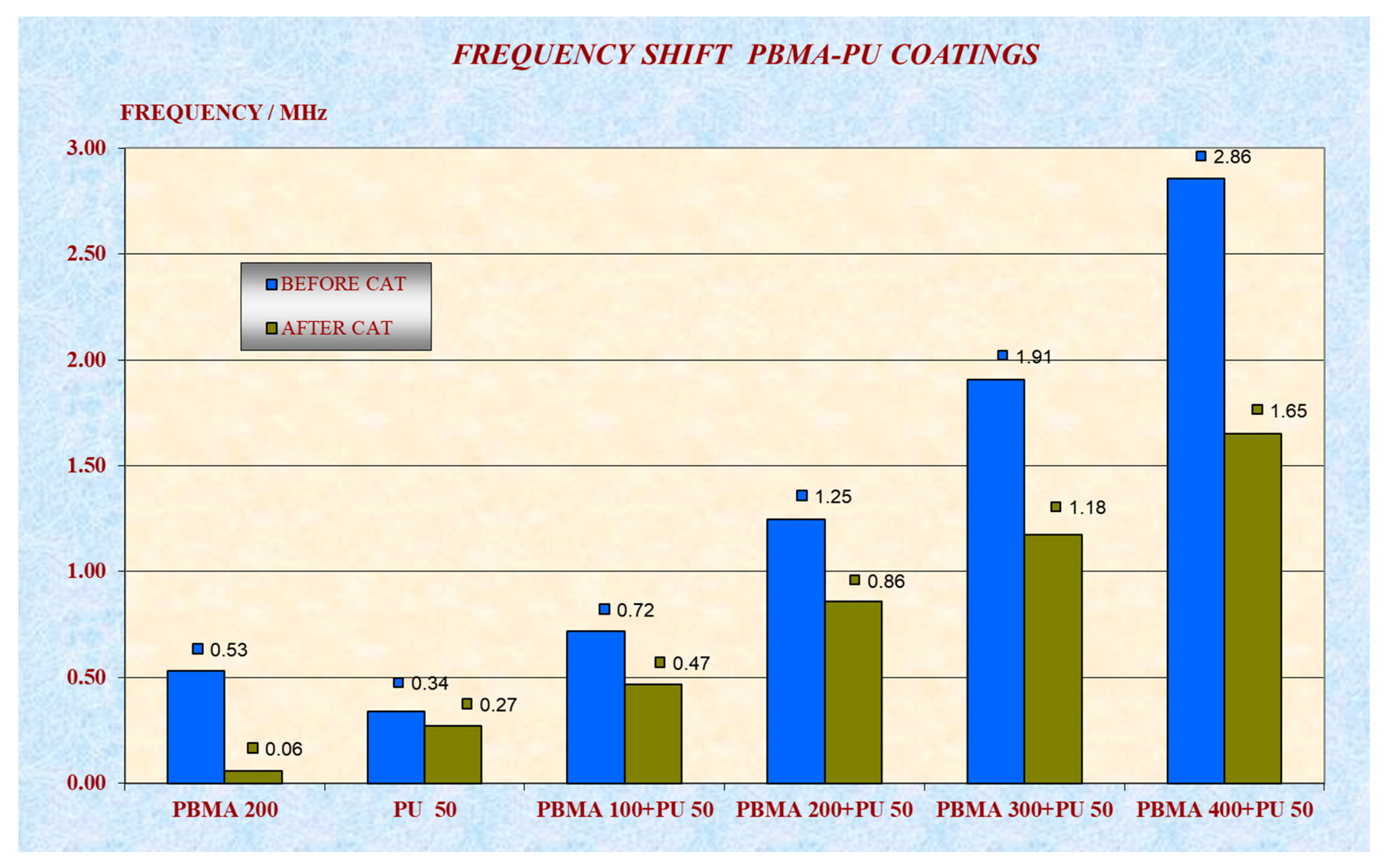
Figure 5 presents the changes in the frequency shifts before and after the CAT for all of the coatings described in Table 1. From Figure 5, it can be seen that the coating with PBMA as the single polymer has its coating layer practically removed after the CAT, while for all of the coating layers containing PU in pure form or in one of the PU–PBMA composites, a substantial quantity of their coating material was retained after the CAT.
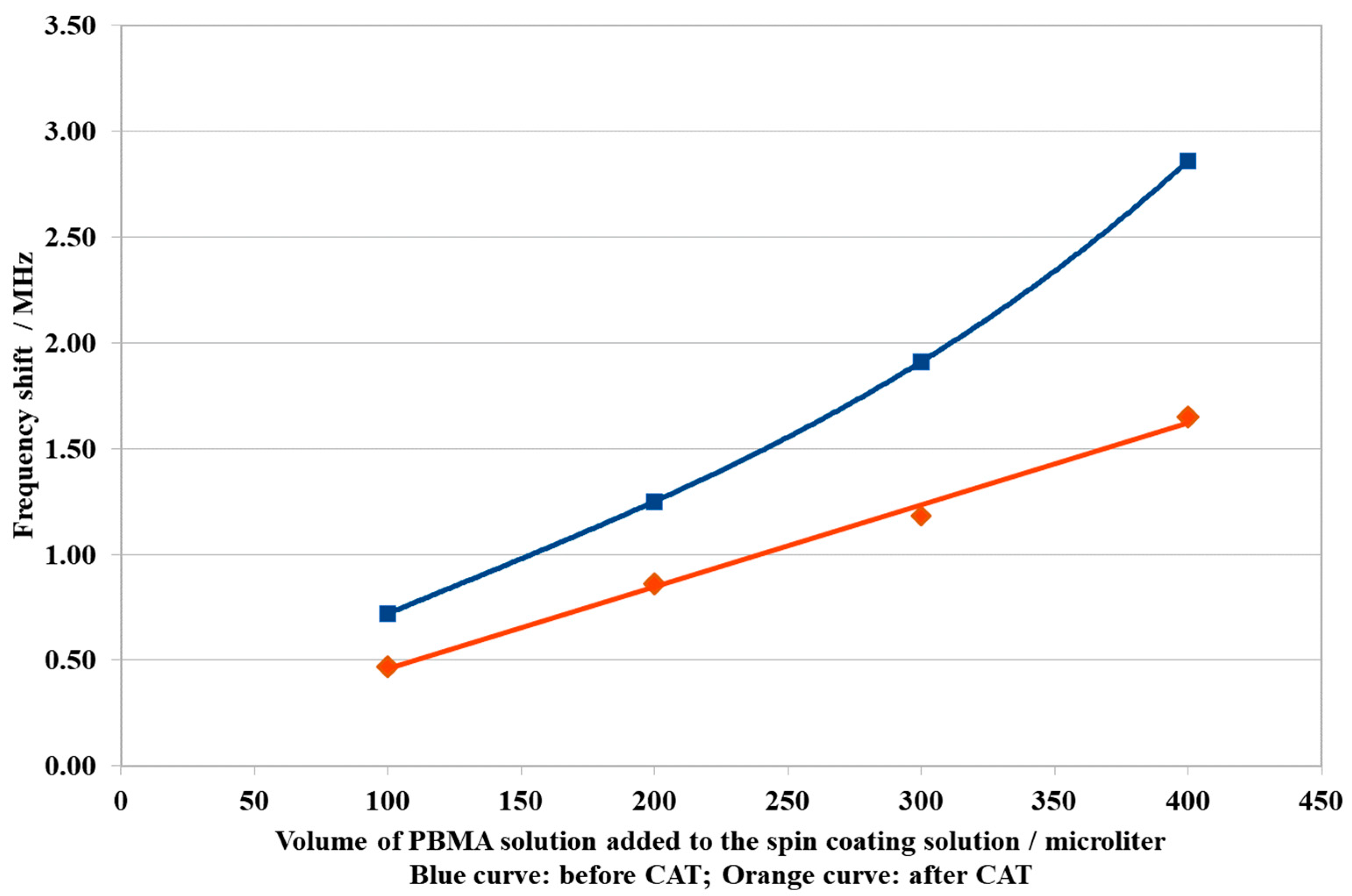
Figure 6 presents the frequency shifts after the coating process as a function of the volume of the PBMA solution added to the spin coating solution. The zero volume refers to no addition of PBMA, when only the PU solution was added to the spin coating solution. In this research, it was seen that the increase in the volume of the PBMA solution causes a consequent increase in the deposited mass, as expressed by the increase in the frequency shift.
The curve in Figure 6 is a third-degree polynomial interpolation that very accurately describes the behavior of the frequency shift in terms of the PBMA quantities in the spin coating solution, represented by the volume of PBMA added to the solution.
These results show a very precise relationship between the concentration of the polymers in the spin coating solution and the mass of the coating layer deposited, which is directly related to the frequency shift results. The precision observed in the results also indicates the reliability of the coating process.
The same analysis was carried out for the results of frequency shifts after the CAT. Figure 7 shows a graphic for the linear interpolation for the obtained values of frequency shift after the CAT for the PU–PBMA composites. The results show a high degree of correlation (R2 = 0.995) between the observed frequency shift and the polymer concentration in the spin coating solution; in this case, however, the correlation is linear in its form.
The results after the CAT showed a very precise correlation and a clear profile for the relationship between the composition of the spin coating solution and, in this case, the remaining mass of the coating layer after the CAT.
Figure 8 presents the profiles for the relationship of the frequency shift and the polymer concentration in the spin coating solution, observed before and after the CAT, for a better comparison of the difference between the originally deposited and remaining mass of the coating layers after the CAT.
In addition to the fact that the mass of the coatings was removed to some extent in all of the PU–PBMA composites after the CAT, the linearity obtained for the data of the frequency shift against the polymer concentration in the spin coating solution after the CAT (Figure 7) showed a different behavior than that observed before the CAT, as presented in Figure 6.
A possible explanation for these observations could be as follows. When the spin coating solution is converted into the coating by the removal of the excess dispensed polymer solution and solvent, the remaining relative concentration of the polymer and its respective spatial distribution will form the resulting PU–PBMA composite, whose constitution is closely correlated to starting spin coating solution.
The fact that the coating layer with only PBMA was washed out after the CAT and does not occur when the PU is the only coating material of the layer (Figure 5) indicates that the presence of PU is responsible for the observed resistance to the CAT. This is reinforced by the fact that all of the formulations containing PU and PBMA presented a higher resistance to the CAT than for the coating with only PBMA.
From the results, it can be inferred that after the formation of the coating layer with the composite materials, the most of the polymer are in the form of the composite, where the PU accounts for two effects: the enhancement in the adhesion of the coating layer to the surface, and the entanglement with the PBMA in such a structure, which makes the composite resistant to the CAT. However, some quantity of the PBMA is still in a free form in the coating layer, being not completely bonded in the form of a composite with PU. Therefore, this part of the unbonded PBMA could be removed from the coating layer by the CAT.
This assumption can explain why some mass is removed by the CAT from the PU–PBMA composites coatings (Figure 8), and why the curves of the frequency shift as a function of the PBMA concentration before (Figure 6) and after the CAT (Figure 7) presented different quantitative profiles.
In all of the coating solutions of the PU–PBMA composites, the PU quantity was maintained constant and the PBMA quantity was increased, as shown in Table 1. By the assumption of the formation of PU–PBMA composites, for a given mass of PU there would be a limit for the proportion between the PU and PBMA, which can lead to a composite with a stable structure that is resistant to the CAT. In the case of a larger excess of PBMA, it is expected that a larger quantity of this polymer will be not incorporated into the composite structure, remaining as free PBMA. This statement can explain the observation that the more the PBMA is increased in the formulation, the larger is the mass removed from the layer on the sensor surface (Figure 8).
It is important to note that the all of the results of the frequency shifts before and after the CAT show a high degree of reproducibility and precision, confirmed by the profiles obtained as a function of the concentration of PBMA on the composites.

3.2.2. Attenuation

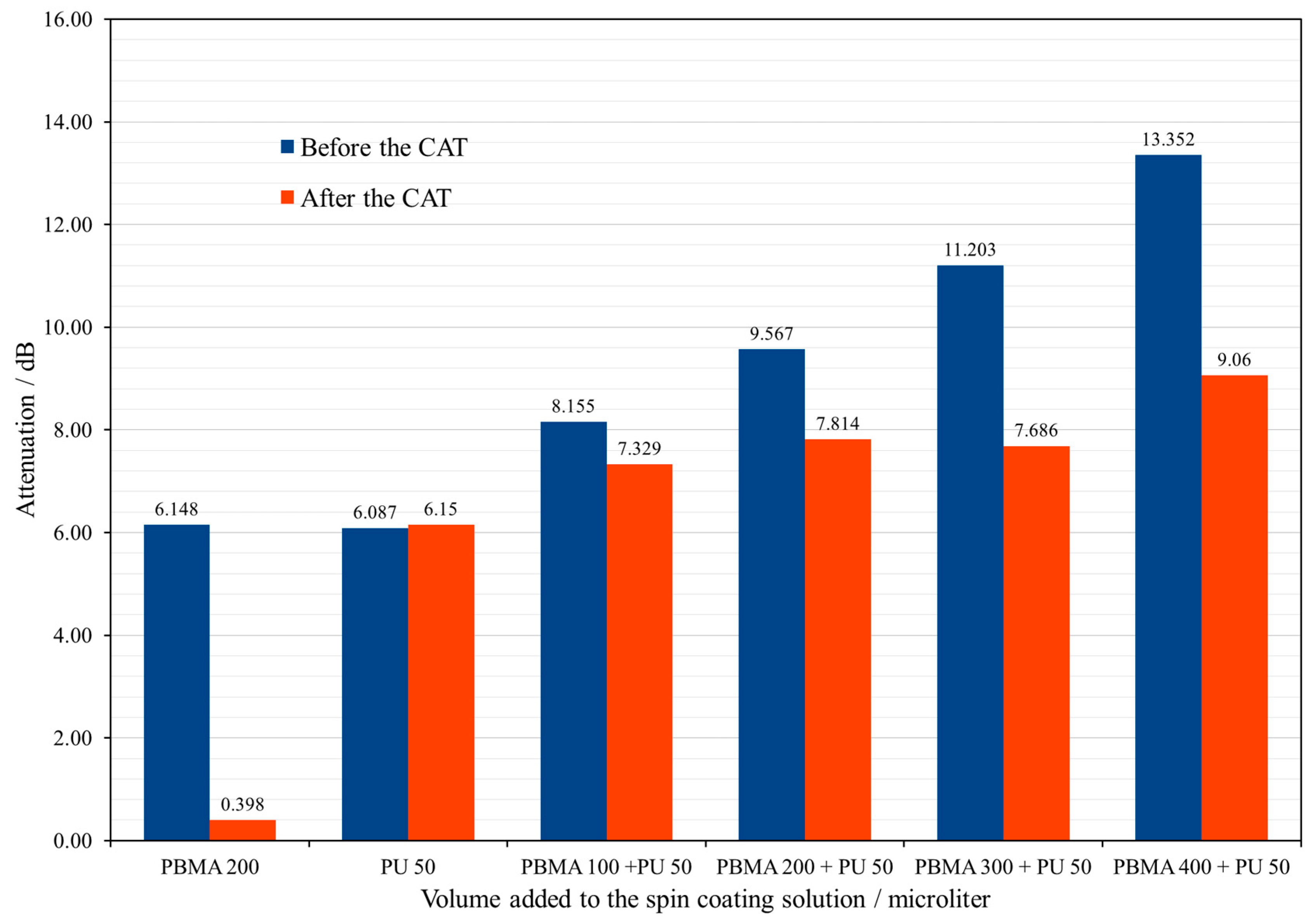
The results for the attenuation for each coating before and after the CAT are shown in Figure 9.
The attenuation results provide information about the influence of the coating layer on the propagation of the surface acoustic wave over the active area of the sensor element. From the results before the CAT, the coatings layers with just the PBMA and PU polymers, the attenuation had practically the same value (Figure 9), indicating that both coatings present the same behavior regarding the propagation of the surface wave.
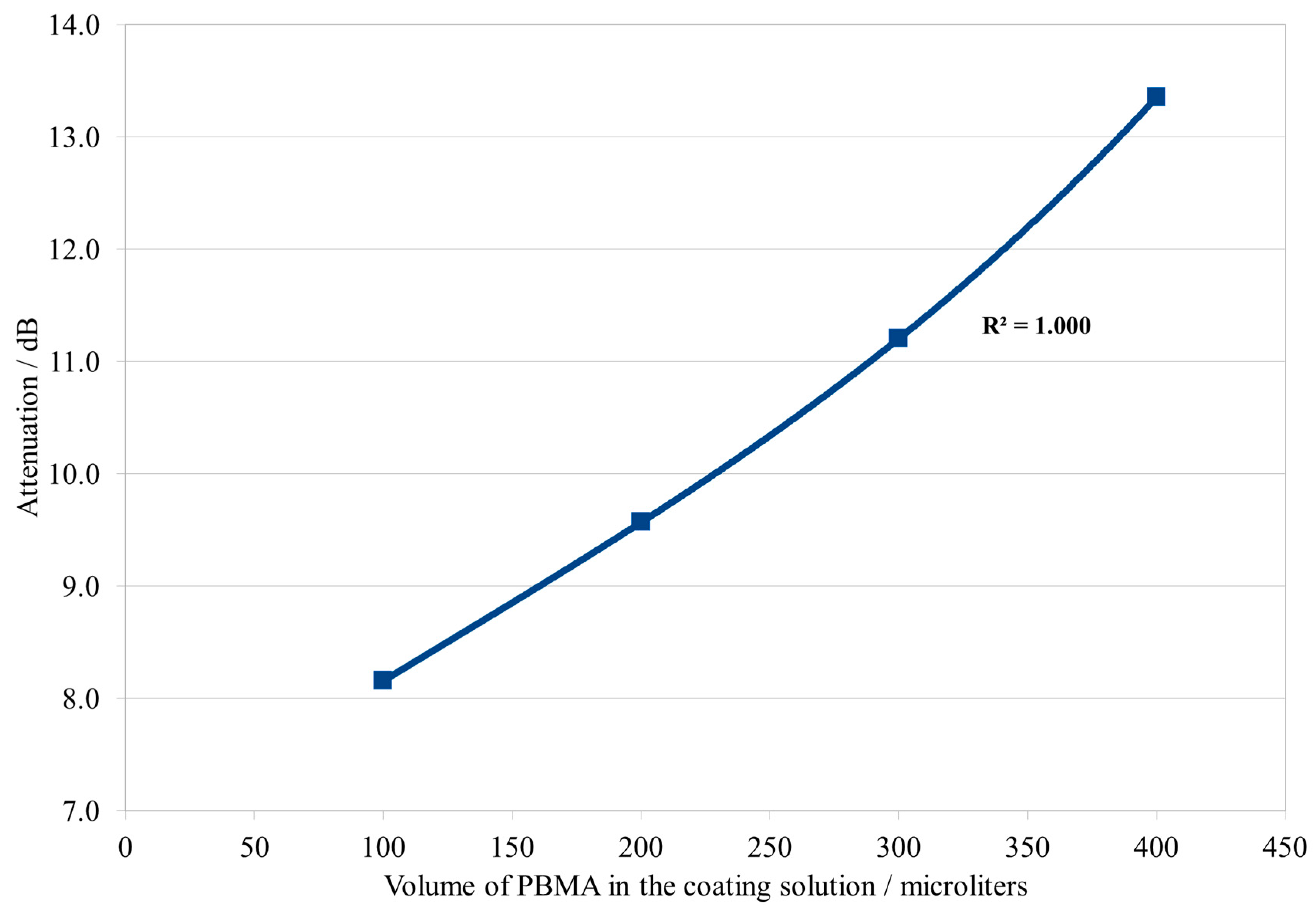
For the layers of the PU–PBMA composites, the results of the attenuation before the CAT increased with the concentration of the polymers, as expected. However, the form of the relationship between the attenuation and the concentration of the PBMA again resulted in an exact profile, as presented in Figure 10.
The profile obtained for the attenuation as a function of the polymer concentration is in the same form from that observed for the frequency shift (Figure 6). This observation, as expected, confirms that the increase in the attenuation was due to the increase in mass that occurs with the increase in the polymer concentration on the coating solution.
However, the important result in this study is the exact correlation observed in Figure 10, suggesting that the increase in the attenuation is just due to the increase in the effective mass over the SSE, and not due to other structural effects like differences in the morphology of the composites’ coating layers, or to possible differences in the homogeneity of the material distribution over the active surface of the SSE. The results indicate the homogeneity of the formation of the composite layers and of their resulting structures, as well as the reliability of the coating procedure.
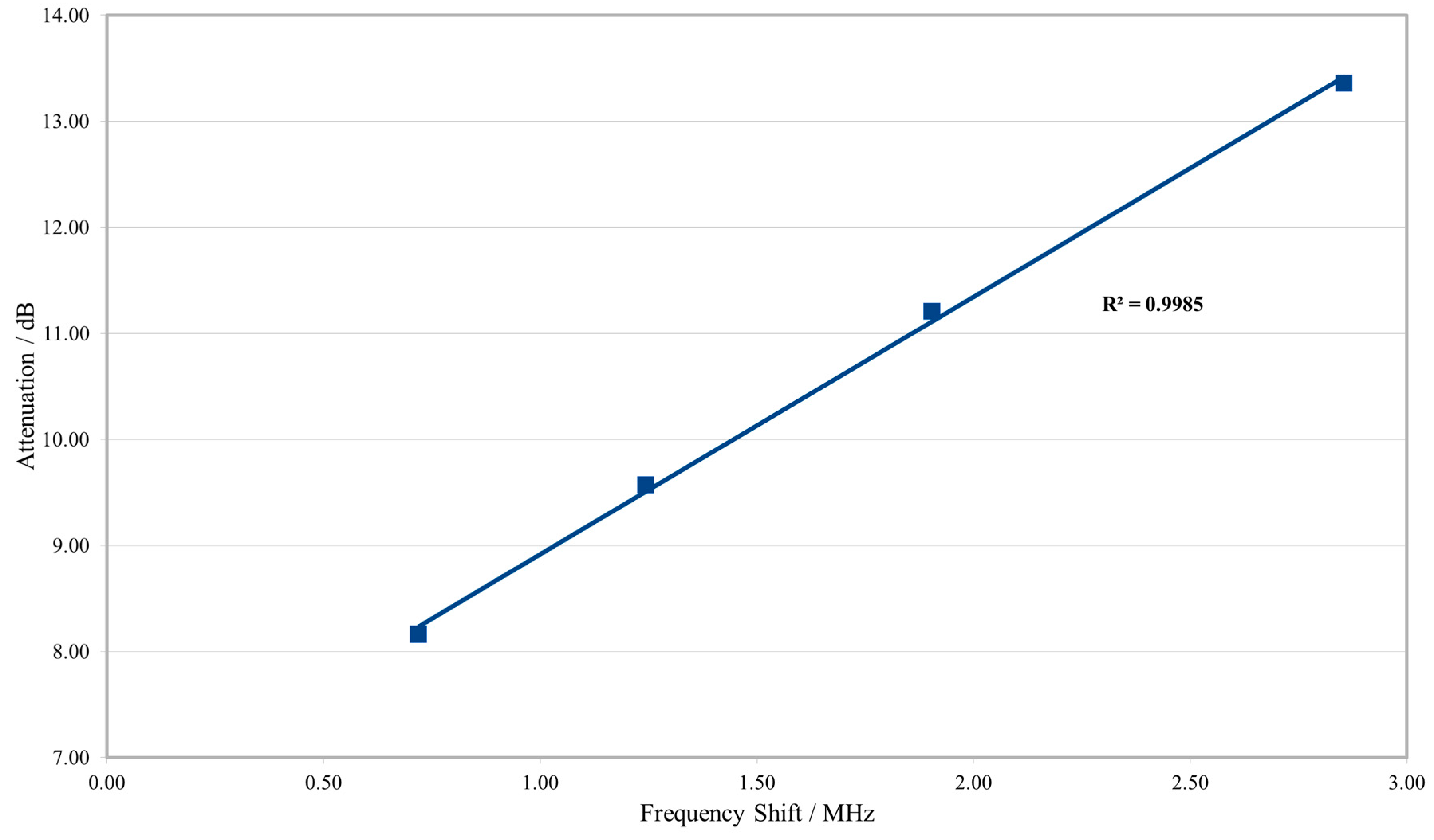
This can be better visualized by graphing attenuation versus frequency change for the PU–PBMA composites (Figure 11) before the CAT. The observed correlation indicates, therefore, that the increase in attenuation for the composites is due just to the increase in mass on the surface.
From the results before the CAT, it can be inferred that the PU–PBMA composites present high homogeneity in their process of formation, thus resulting in coatings with similar structures. The coating procedure provided a homogeneous distribution of the material over the surface, which did not show any influence on the attenuation results.
For the attenuation results values observed after the CAT (Figure 9), the results for the coating with pure polymers were those as observed by the frequency shift (Figure 5). The coating with only PBMA was almost completely washed out, while the PU coating layer showed practically no significant alteration after the CAT.
The overall reduction of the values for the attenuation observed after the CAT for the PU–PBMA composites (Figure 9) can be explained by their respective mass reductions suffered after the CAT, which can be inferred from the results of their frequency shifts after the CAT (Figure 8).
Considering that the attenuation reflects an integral property of the coating layer that results from factors like the structural homogeneity of the layer, homogeneity of the distribution of the coating material, material quantity deposited and the viscoelastic properties of the coating material, the PU–PBMA composites also presented consistent results after the CAT.
With the loss of mass experienced by all of the PU–PBMA formulations after the CAT, the coating layers of the composites became increasingly similar in terms of their deposited quantity of material (Figure 8) and in terms of their structures, considering that practically just the PU–PBMA composites remained after the CAT. As discussed before, the composite layers seem to be remarkably similar in terms of their formation and, therefore, in their structure also. Considering this, it is expected that the layers should present similar values for the attenuation after the treatment of the CAT, as observed in Figure 9.
This argument can be used to explain why the formulations represented by 100, 200 and 300 microliters of PBMA show similar results in attenuation after the CAT (Figure 9), while the coating obtained with the formulation with 400 microliters presented a slightly higher value for the attenuation, probably because this layer retained more material after the CAT in comparison to those with lower polymer concentrations.

3.3. Sensor Response Analysis

The next results present the relative sensor responses for the coating materials listed in Table 1 for the ten substances analyzed. The relative sensor responses for chloroform, isopropanol and water will be used to exemplify and generalize the results of the analyses of the other analytes.
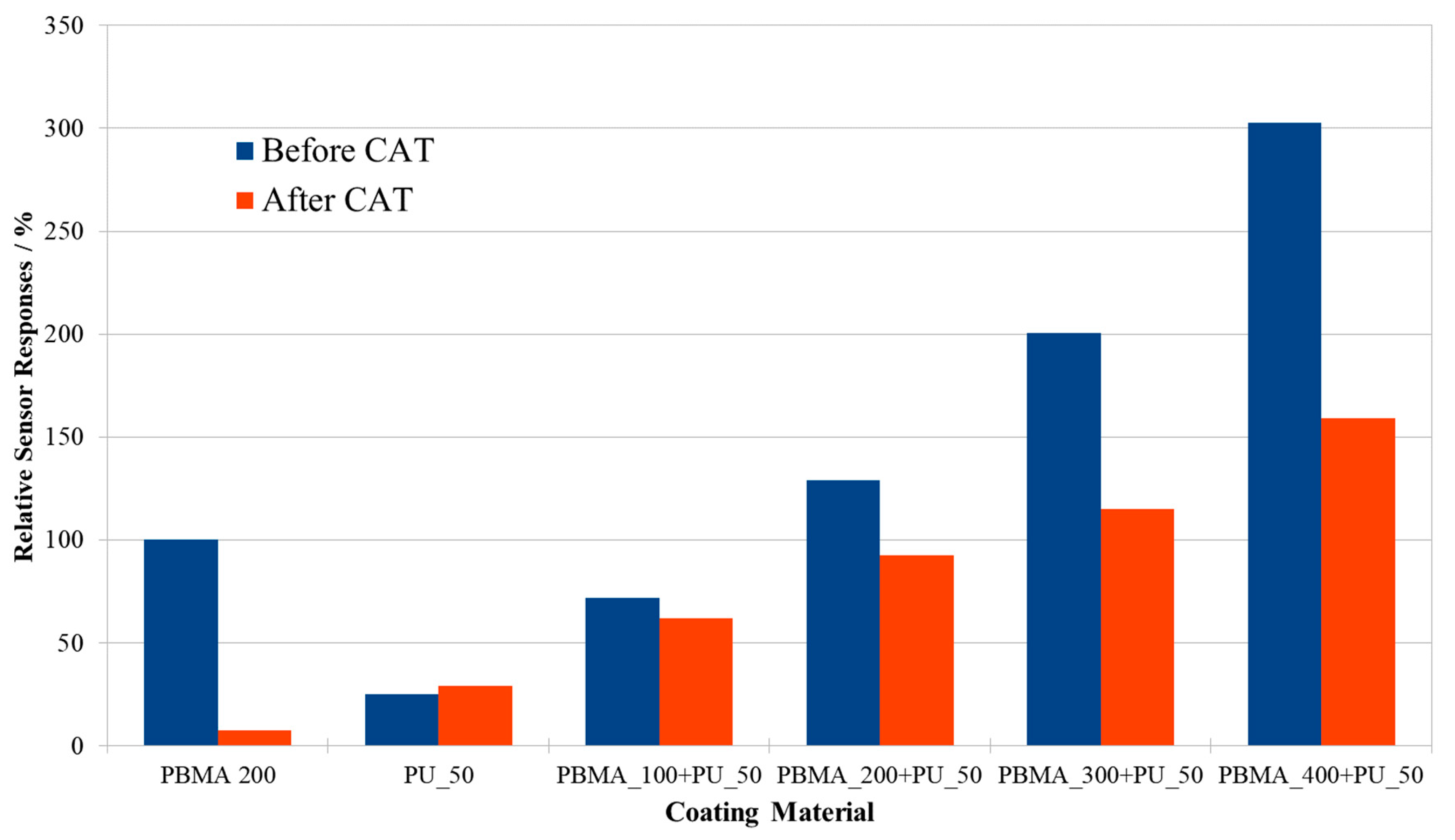
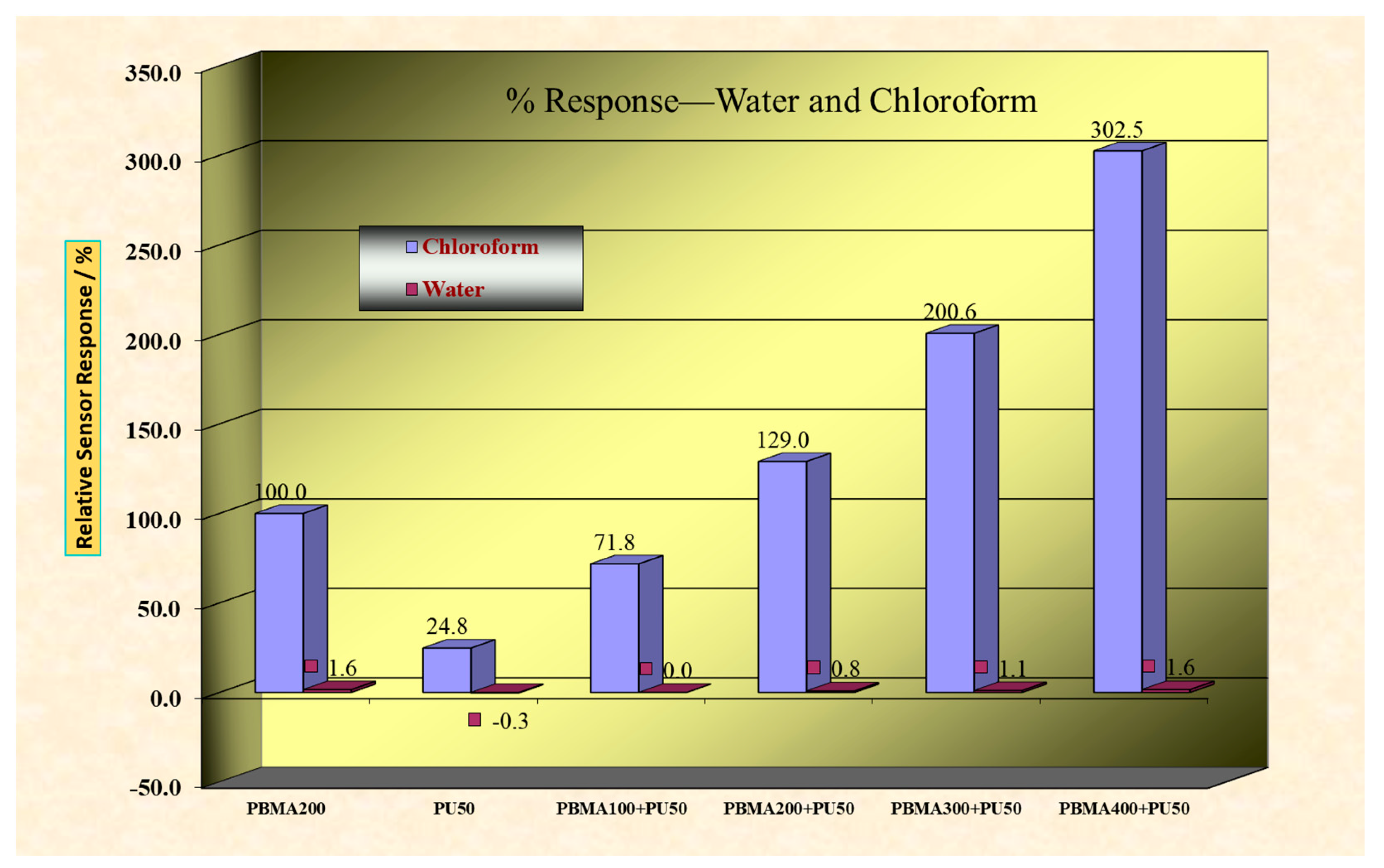
Figure 12 presents the relative sensor responses for chloroform, before and after the CAT.
From Figure 12, the relative sensor response for chloroform by the PU-coated sensor is smaller than the relative sensor response of the PBMA-coated sensor. This is why the PBMA is called the sensing polymer, for the sensor responses are mostly due to its presence and quantity in the coating materials.
After the CAT, the PU coating was preserved, with a slight increase in its relative sensor response for chloroform. This observation will be discussed later. The relative sensor response of the PBMA coating after the CAT was almost completely lost, while for the PU–PBMA composites, some loss in the original relative sensor responses for chloroform was observed (Figure 12).
The small increment observed in the sensor response for the PU sensor to chloroform (Figure 12) contrasts, however, with the equally small loss in mass observed in the frequency shift of this sensor after the CAT (Figure 5).
As will be seen by the subsequent results, the relative sensor responses for the PU sensor are small for all of the analytes, which indicates an accordingly smaller sorption of the analyte into the coating layer structure compared to that observed for the sensing polymer (PBMA). Therefore, for the PU coating layer, the sensor responses should be more sensitive to the superficial area of the coating layer than to the mass of the layer itself.
In this sense, the removal of the mass observed by the immersion on the solvent during the CAT probably “scavenged” the surface of the coating layer, which became more irregular, leading to an increase in its superficial area, resulting in a small increase observed in the relative sensor response.
Concerning the PU–PBMA composites, after the CAT, all of the sensors preserved a significant part of their original relative sensor responses for chloroform (Figure 12), reproducing the patterns observed for the results of the frequency shift due to the coating deposition (Figure 5). The results of the sensor responses for chloroform corroborate the assumptions made before about the formation of the PU–PBMA composites.
The agreement in the results of the relative sensor responses (Figure 12) with those obtained for the frequency shift due to the coating process (Figure 5) indicates that the relative sensor responses are in a direct relationship to the actual mass of the coating layer. Although this fact would be expected, the results of the relative sensor responses for chloroform validate the interpretation of the data, and confirm the homogeneity and robustness of the coating process.
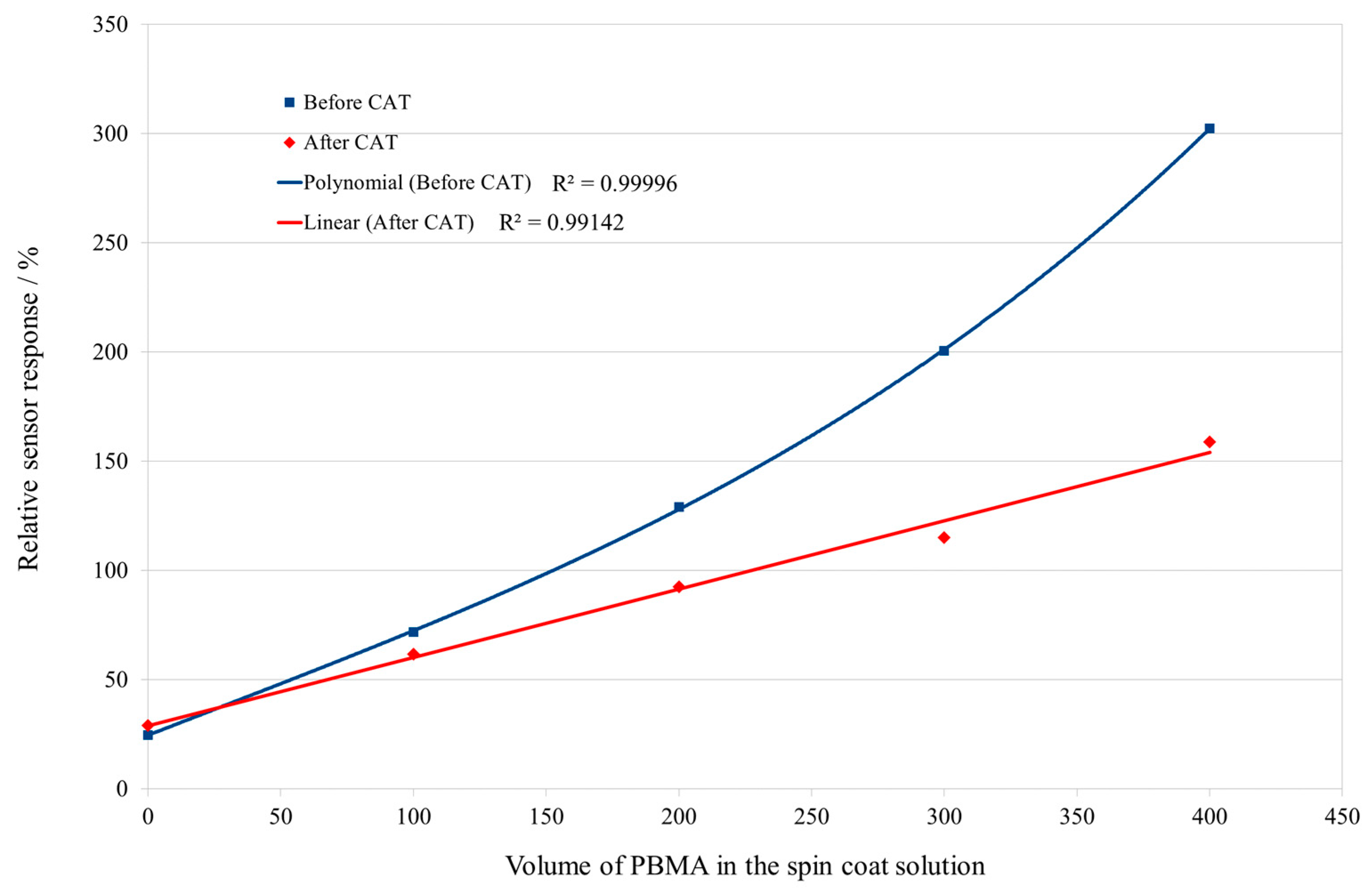
The quantitative relationship between the relative sensor responses for chloroform and the added volume of PBMA in the spin coating solutions is shown in Figure 13.
The curves in Figure 13 present the same profiles observed for the results of the frequency shift due to the coating of the sensors (Figure 6 and Figure 7), which indicates that the relative sensor responses for the chloroform are closely correlated to the frequency shifts obtained by the ultrasonic measurements. The quantitative profiles obtained for the relative sensor responses for chloroform (Figure 13) are very precise, reproducing the same precision observed for the results for the frequency shift measurements (Figure 8). These results demonstrate the close and precise correlation of the sensor responses with the constitution of the coating materials.
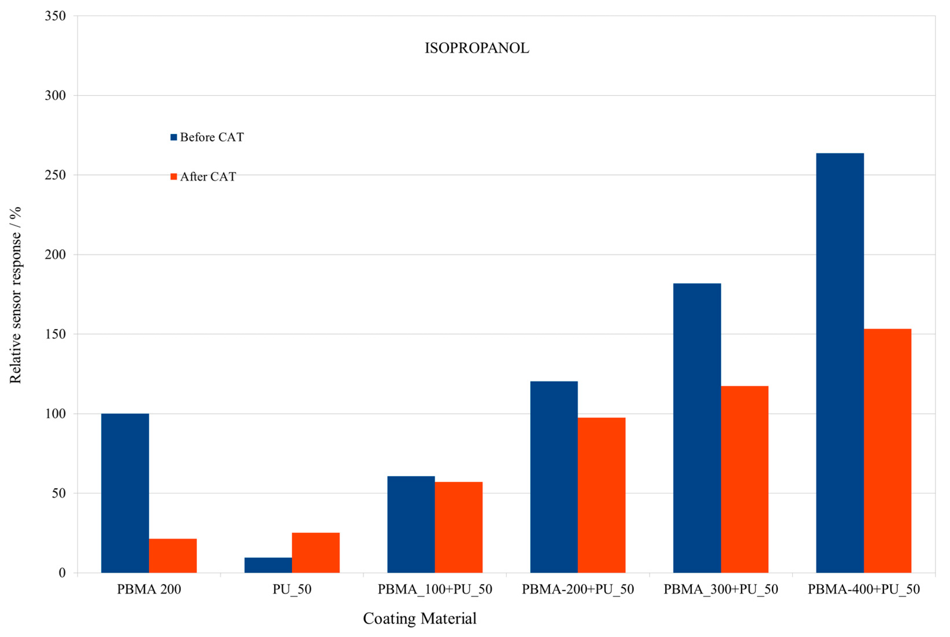
The same analysis was performed with isopropanol as the analyte, in order to compare with the results obtained for chloroform. The results of the relative sensor responses for isopropanol are shown in Figure 14.
As expected, there are differences in the values of the relative sensor responses for isopropanol and chloroform (Figure 12 and Figure 14). The relative sensor responses for chloroform are higher for all of the PU–PBMA composites than for isopropanol. These results indicate that the coating materials may have a higher chemical affinity to chloroform in comparison with isopropanol. The affinity of the analytes for the PU–polymer composites will be discussed in a future study.
The same behavior was observed for the PU sensor; its relative sensor responses after the CAT are higher than before the test, corroborating the previously made assumption.
Despite of the chemical differences between chloroform and isopropanol, the pattern for the relative sensor responses for both analytes present exact the same behavior with respect to all of the coating materials (Figure 12 and Figure 14).
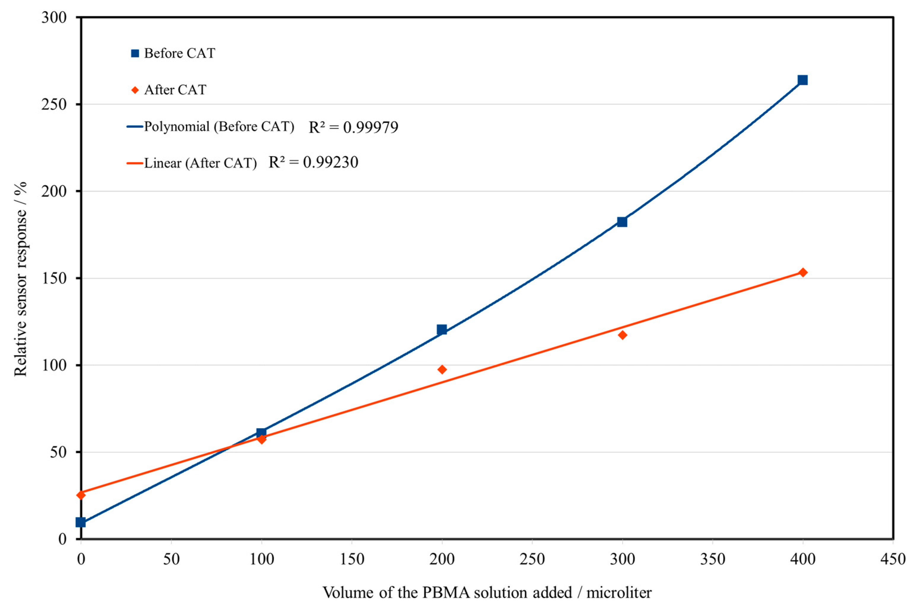
Consequently, the plots of the relative sensor response for isopropanol against the volume of the PBMA solution added to the coating solution, shown in Figure 15, present the same profiles obtained for the chloroform as the analyte (Figure 13), and could be also described by the same mathematical functions for the data before and after the CAT.
This agreement between the profiles for the relative response for both analytes suggests that the same process drives their interaction with the sensing layers and supports the assumption of the correlation between the composition and structure of the PU–PBMA composites.
The agreement of the profiles before and after the CAT for the relative sensor responses as a function of the layer composition for both analytes and the results of the frequency shift due to the coating process (Figure 8) demonstrates the influence of the constitution of the coating layers, in terms of their mass and structure, on the sensor responses.
Before the application of the CAT, the results of the ultrasonic parameters and of the relative sensor responses suggest that very reproducible structures are obtained with the coating procedure. Both the ultrasonic results as well as the relative sensor responses show a very constant and correlated behavior that is in close agreement with the actual mass of the coating layer (Figure 8).
In the limit situation presented by the CAT, the formulations with PU lead to the formation of stable composites with the sensing polymer (PBMA) in terms of both its adherence to the surface and of its resistance to the organic solvent, which easily solubilizes the pure sensing polymer.
The composites that remain after the CAT presented, in the same way, a very reproducible behavior in terms of their relative sensor responses for both analytes for all of the PU–PBMA formulations, even considering some loss in the mass that was originally deposited.
A possible interpretation for the different behaviors observed before and after the CAT is as follows. For the formulations of the coating materials (Table 1), it can be expected that different composites are formed whose composition depend on the proportion of PU and PBMA present in the spin coating solution.
By the spin coating process, after the dispensing of the spin coating solution, the solvent is quickly removed from surface of the SSE, leaving part of the deposited mass as the newly formed PU–PBMA composite, and a part in the form of free PBMA unbounded to the structure of the composite.
The results of the original coating deposition as well as the results of the remaining composites were very exact and reproducible, being precisely reflected in both the ultrasonic and in the relative sensor responses results.
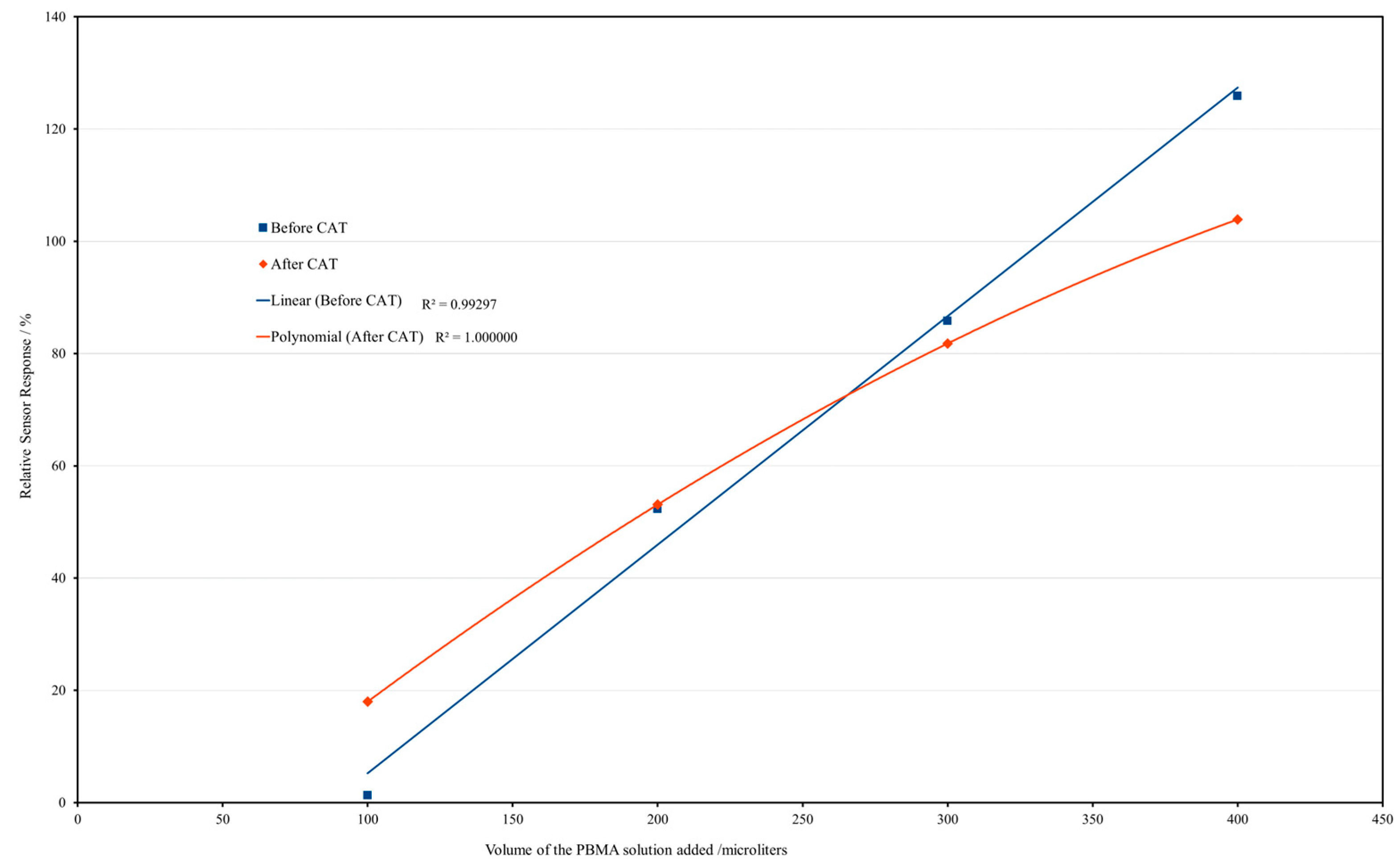
The results after the CAT indicate that the composites present a linear relationship with the quantity of PBMA in the spin coating solution (represented by the volume of the PBMA solution added), while the original mass deposited was related to the quantity of PBMA in the form of a polynomial of third degree, as seen in the results before the CAT. To explain the form of each profile obtained, other experiment designs and methodologies are needed to investigate the actual structure of the deposited sensing layer.

3.4. Relative Sensor Responses for Water

Since the results for water as the analyte presented quite different behavior from those observed for the organic analytes, they will be now be analyzed in more detail.
The first important observation is that the sensor responses for water from all of the coating materials were almost negligible when compared with those for all of the other nine organic analytes tested. Figure 16 provides a scale for comparison between the relative response of the sensors for chloroform and water, showing the exceptionally low relative responses to water by all of the coating materials. The reference is the sensor response for the chloroform by the pure PBMA-coated sensor.
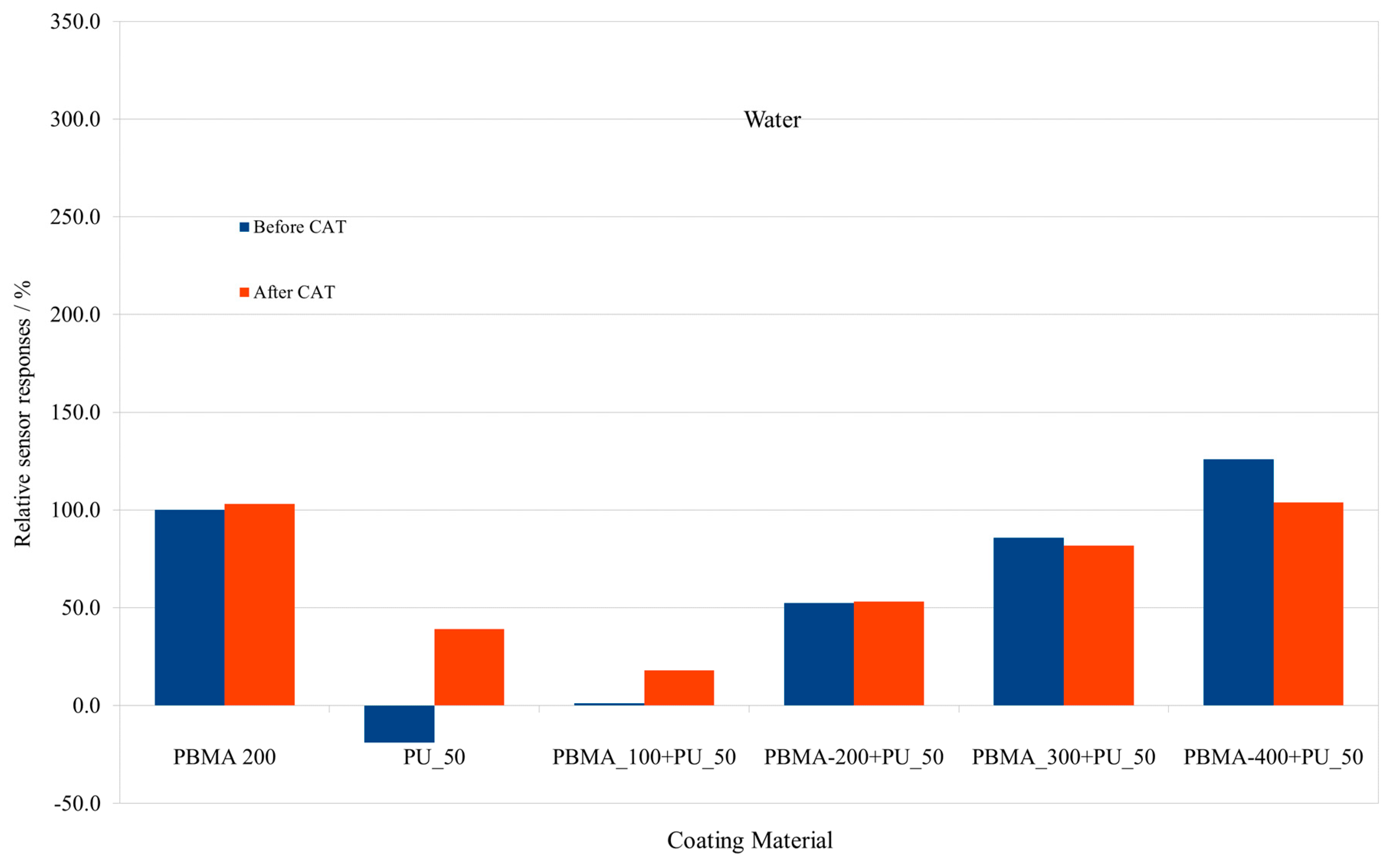
Figure 17 shows the relative sensor responses for water as the analyte, before and after the CAT, now with the sensor response for water by the pure PBMA sensor as the reference (100%), as conducted for the other analytes.
The first important general observation is that the relative sensor responses for water were significantly smaller than those observed for the other analytes. Moreover, the values of the relative sensor responses for most of the coating materials were below that of the reference value obtained for the pure PBMA sensor. This behavior contrasts significantly to that observed for all of the organic analytes.
The next interesting results are those for the relative sensor responses for water by the pure PBMA-coated sensor, shown in Figure 17. From previous results, it was observed that just a small fraction of the original pure PBMA coating remained after the CAT (Figure 5). And despite this fact, the relative sensor responses for the water before and after the CAT were remarkably similar, indeed being a little higher after the CAT, for the sensor coated with pure PBMA. This means that the sensor response for water was independent of the mass of the coating layer present.
A possible explanation for these observations, together with the fact of the negligible values of the relative sensor responses observed for water, is that the interaction may occur just by adsorption of water at the surface of the coating layers. In contrast, the organic analytes are absorbed into the structure of the sensing layer, and give rise to the higher values typical of the relative sensor responses obtained for the organic analytes.
The fact that comparable or even higher relative sensor responses after the CAT were observed for most of the coating materials (Figure 17) is also an indication that a different process from that observed for the organic analytes governs the interactions of the water with the coating materials.
The relationship of the relative sensor responses for water as a function of the PBMA concentration in the spin coating solution are shown in Figure 18.
The profiles of the curves in Figure 18 are quite different from those observed for the previous analytes (Figure 13 and Figure 15), which also indicates a different kind of interaction between water and the PU–PBMA composites than that observed for the organic analytes.

3.5. Sensor Responses for the Organic Analytes

The results for the relative sensor responses obtained for all of the organic analytes tested and water are now presented. For a better comparison, the analytes were grouped according to their chemical functions or chemical similarities, and the results obtained before and after the CAT are shown in separated graphics for each group of analytes.
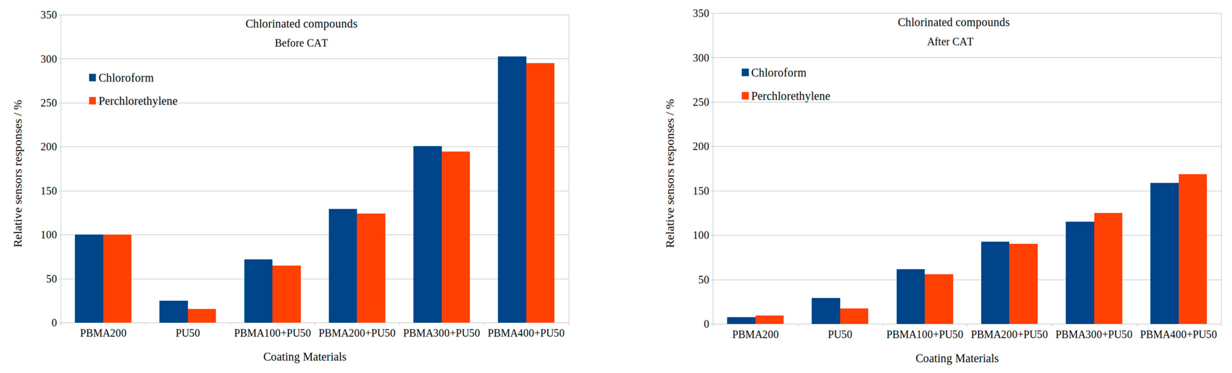
Figure 19 shows the relative sensor responses for the chlorinated substances, chloroform and perchloroethylene.
The relative sensor responses for the perchloroethylene follow the pattern observed for chloroform for all of the coating materials, before and after the CAT, reproducing the behavior observed after the CAT due to partial removal of the coating. The values of the relative sensor responses are comparable for both compounds, with the results for chloroform being slightly higher.
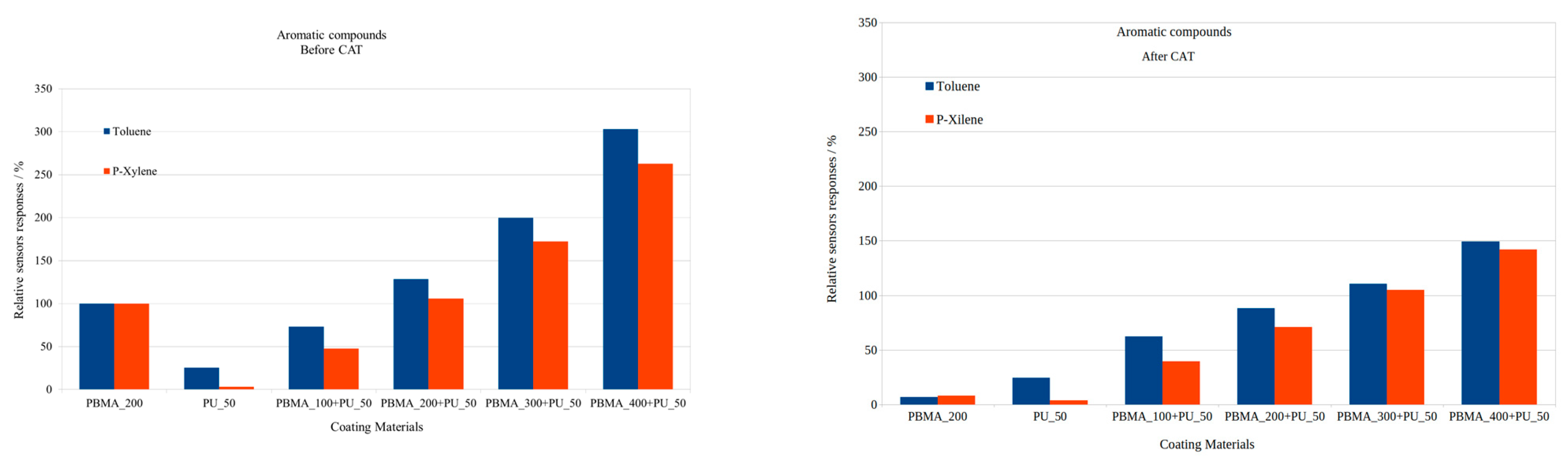
Figure 20 presents the results of the sensor responses for the aromatic analytes.
The patterns observed for the aromatic analytes follow the same pattern as observed for the chlorinated analytes. It is interesting to note that relative sensor response of the pure PU sensor for p-xylene is lower than those observed for the other analytes, including the relative sensor response of the PU sensor for toluene.
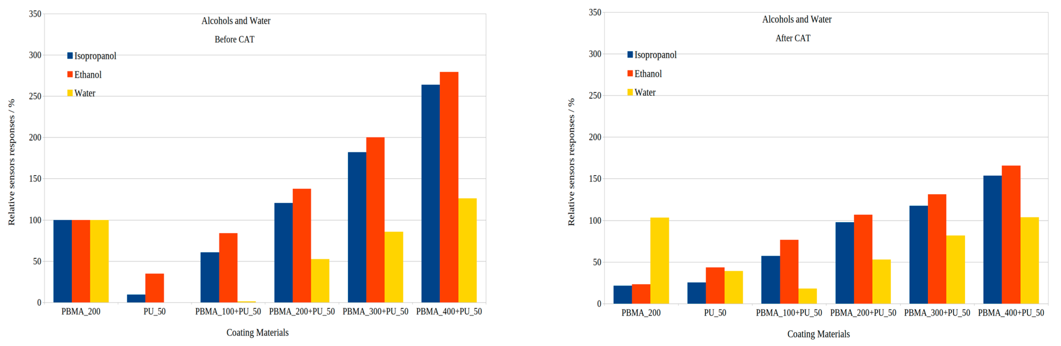
The results for the alcohols, isopropanol and ethanol, are shown together with those for water in Figure 21.
While the relative sensor responses of both alcohols followed the patterns obtained for the other organic analytes, this agrees with the patterns for the frequency shifts due to the deposition of the coating materials (Figure 8). The relative sensor responses for water show a very distinct behavior when compared to the responses to the alcohols and all of the other organic analytes, indicating a different mechanism of interaction, as previously discussed.
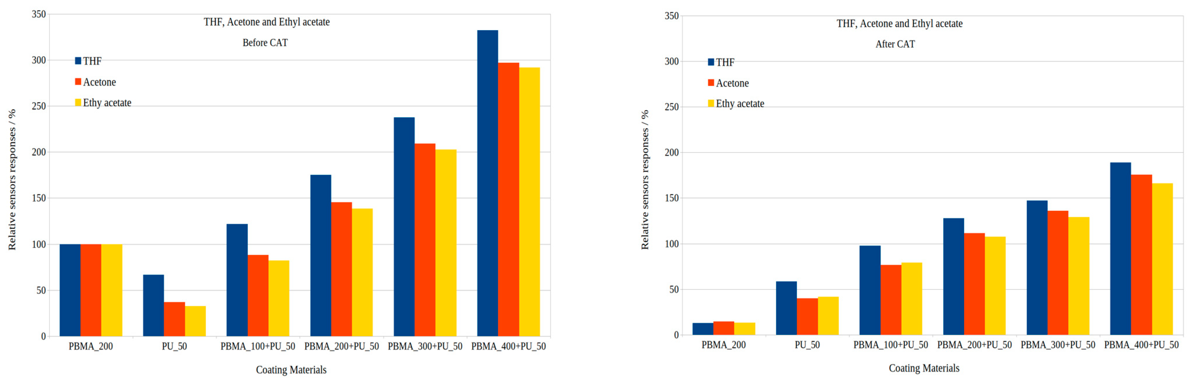
Finally, Figure 22 presents the results for the compounds acetone, ethyl acetate and THF. These compounds are representative of the ketone, ester and ether chemical functions, respectively.
The results for the relative sensor responses of these three organic analytes indicate in the same way the patterns observed for the other analytes, for both conditions, before and after the CAT. The differences observed in the values of the relative sensor responses reflect the extent of the chemical affinity of each analyte to the coatings with the PU–PBMA composites.
From these results, all of the organic analytes show the same patterns for the relative sensor responses for the coating materials, for both conditions, before and after the CAT. The differences in the intensity of the relative sensor responses, probably due to the different chemical affinities between the coatings and the analytes, do not invalidate the reproducibility of the pattern observed. The results indicate that all of the organic analytes appear the follow the same mechanism of interaction with each of the coating materials. The exceptions are the results for water, which presented a different pattern from that observed for the organic analytes, suggesting a different mechanism of interaction with the coating materials.

4. Conclusions

The new coating materials variants obtained from the different PU–PBMA proportions (Table 1) presented results for the ultrasonic parameters that are qualitatively and quantitatively very consistent, revealing a direct correlation with the PBMA concentration in the coating solutions. The attenuation results show a precise correlation with the PBMA concentration in the spin coating solution.
The frequency shift results after the CAT show a consistent loss in mass by the layers, maintaining, however, a close relationship with the PBMA concentration in the spin coating solutions. However, the results for the attenuation after the CAT presented a different profile as a function of the concentration of PBMA in the spin coating solution, indicating constancy in terms of the homogeneity of the coatings.
The relative sensor responses reproduced the profiles observed for the results before and after CAT for the frequency shift for the materials listed in Table 1 (Figure 8), indicating a quantitative correlation with the frequency shift. The identical profiles obtained for the ultrasonic parameters and for the relative sensor responses indicate a closer relationship between the composition of the spin coating solution and the resulting composition of the obtained coating layer.
The CAT results show that all of the resulting PU–PBMA composites present a remarkable resistance to immersion in perchloroethylene when compared to that for pure PBMA. It is expected that the results can be extrapolated toward a chemical resistance to long-term exposure to organic vapors. The new composite materials showed significant improvement in adhesion in comparison to the coating using pure PBMA.
The results attest to the high reproducibility of the whole process, from the spin coating process to the formation of the coating layer, which were preserved after the CAT. The relative sensor responses are, as expected, due almost exclusively to the sensing polymer (PBMA), while the PU has negligible influence on the relative sensor responses for the organic analytes.
The results also strongly suggest that the structures of the PU–PBMA sensing layers were formed in a very uniform and reproducible way and, even after immersion in the organic solvent by the CAT, the coating layers of the PU–PBMA composites do not lose their capacity for response; most importantly, after the CAT, they both showed qualitatively and quantitatively preserved profiles for their relative sensor responses to all of the organic analytes. These facts indicate that even though the values of the relative sensor responses were reduced after the CAT, the structure of the composite sensing layers appeared to be preserved.
The loss of mass observed after the CAT is due to the removal of some free PBMA, which did not combine with PU in the form of a composite. Despite of the removal of the free PBMA, the sensor responses of the PU–PBMA composites after the CAT showed a constant and reproducible profile for the quantitative relationship to the coating composition, yet showed a different profile than the results obtained for before the CAT.
The PU showed two important functions: it acts as a binder to form the composite with the PBMA; and it improves the adhesion of the PU–PBMA coating layers to the surface of the SSE. The new coating materials showed a negligible response to water, which is important for the analyses of complex organic matrices, as is the case for foods and other natural products, where water is eventually considered an interferent for analytical purposes.
All of the results with the new coating materials indicate the robustness and reproducibility of the coating method, which provides a reliable method for the sensitization of SAW sensors.
In the future, the concept of composites with PU as SAW sensor coating materials will be applied to other sensing polymers, in order to investigate the effects of the structure of the sensing polymer on the properties of the coating layer.

Author Contributions

Conceptualization, M.d.S.d.C. and M.R.; Methodology, M.d.S.d.C. and A.V.; Software, A.V.; Validation, A.V.; Formal analysis, M.D.; Investigation, M.d.S.d.C. and M.R.; Resources, M.R.; Data curation, M.D.; Writing—original draft, M.d.S.d.C.; Writing—review & editing, M.d.S.d.C.; Project administration, M.R. All authors have read and agreed to the published version of the manuscript.

Funding

We acknowledge the support by the KIT-Publication Fund of the Karlsruhe Institute of Technology.

Institutional Review Board Statement

Not applicable.

Informed Consent Statement

Not applicable.

Data Availability Statement

Data are contained within the article.

Conflicts of Interest

The authors declare no conflict of interest.

References

  1. Sberveglieri, G.; Genzardi, D.; Greco, G.; Nunez-Carmona, E.; Pezzottini, S.; Sberveglieri, V. The Eletronic Nose: Review on Sensor Arrays and Future, Perspectives. Chem. Eng. Trans. 2022, 95, 265. [Google Scholar]
  2. Mujahid, A.; Afzal, A.; Dickert, F.L. An Overview of High Frequency Acoustic Sensors—QCMs, SAWs and FBARs—Chemical and Biochemical Applications. Sensors 2019, 19, 4395. [Google Scholar] [CrossRef]
  3. Devkota, J.; Ohodnicki, P.R.; Greve, D.W. SAW Sensors for Chemical Vapors and Gases. Sensors 2017, 17, 801. [Google Scholar] [CrossRef]
  4. Kumar, A.; Prajesh, R. The potential of acoustic wave devices for gas sensing applications. Sens. Actuators A Phys. 2022, 339, 113498. [Google Scholar] [CrossRef]
  5. Nazemi, H.; Joseph, A.; Park, J.; Emadi, A. Advanced Micro- and Nano-Gas Sensor Technology: A Review. Sensors 2019, 19, 1285. [Google Scholar] [CrossRef]
  6. Mujahid, A.; Dickert, F.L. SAW and Functional Polymers. In Gas Sensing Fundamentals; Kohl, C.-D., Wagner, T., Eds.; Springer: Berlin/Heidelberg, Germany, 2014; pp. 213–245. [Google Scholar]
  7. Dorozhkin, L.M.; Rozanov, I.A. Acoustic Wave Chemical Sensors for Gases. J. Anal. Chem. 2001, 56, 399–416. [Google Scholar] [CrossRef]
  8. Mujahid, A.; Dickert, F.L. Surface Acoustic Wave (SAW) for Chemical Sensing Applications of Recognition Layers. Sensors 2017, 17, 2716. [Google Scholar] [CrossRef]
  9. Milone, A.; Monteduro, A.G.; Rizzato, S.; Leo, A.; Di Natale, C.; Kim, S.S.; Maruccio, G. Advances in Materials and Technologies for Gas Sensing from Environmental and Food Monitoring to Breath Analysis. Adv. Sustain. Syst. 2023, 7, 2200083. [Google Scholar] [CrossRef]
  10. Verma, P.; Yadava, R. Polymer selection for SAW sensor array based electronic noses by fuzzy c-means clustering of partition coefficients: Model studies on detection of freshness and spoilage of milk and fish. Sens. Actuators B Chem. 2015, 209, 751–769. [Google Scholar] [CrossRef]
  11. Palla-Papavlu, A.; Voicu, S.I.; Dinescu, M. Sensitive Materials and Coating Technologies for Surface Acoustic Wave Sensors. Chemosensors 2021, 9, 105. [Google Scholar] [CrossRef]
  12. Rajput, P.; Kumar, J.; Mittal, U.; Nimal, A.; Arsenin, A.V.; Volkov, V.S.; Mishra, P. Thermal sensitivity study of thin film over-layered SAW devices for sensor applications. Inorg. Chem. Commun. 2022, 146, 110116. [Google Scholar] [CrossRef]
  13. Grate, J.W.; McGill, R.A. Dewetting Effects on Polymer-Coated Surface Acoustic Wave Vapor Sensors. Anal. Chem. 1995, 67, 4015–4019. [Google Scholar] [CrossRef]
  14. da Silva, E.A.; Samuel, C.; Furini, L.N.; Constantino, C.J.L.; Redon, N.; Duc, C. Poly(aniline)-based ammonia sensors: Understanding the role of polyurethane on structural/morphological properties and sensing performances. Sens. Actuators B Chem. 2023, 397, 134664. [Google Scholar] [CrossRef]
  15. Ren, X.; Tian, Q.; Zhu, X.; Mi, H.-Y.; Jing, X.; Dong, B.; Liu, C.; Shen, C. Multi-scale closure piezoresistive sensor with high sensitivity derived from polyurethane foam and polypyrrole nanofibers. Chem. Eng. J. 2023, 474, 145926. [Google Scholar] [CrossRef]
  16. Savan, E.K.; Özcan, İ.; Köytepe, S. Preparation of mesoporous carbon containing Polyurethane/Clay nanocomposite membrane-based sensors for sensitive and selective determination of vitamin D2 in urine samples. Measurement 2022, 203, 111979. [Google Scholar] [CrossRef]
  17. Madbouly, A.I.; Hassanien, W.S.; Morsy, M. Tailoring the polyurethane foam/rGO/BaTiO3 pressure sensor for human activities. Diam. Relat. Mater. 2023, 136, 109940. [Google Scholar] [CrossRef]
  18. Hasanzadeh, I.; Eskandari, M.J.; Daneshmand, H. Polyurethane acrylate/multiwall carbon nanotube composites as temperature and gas sensors: Fabrication, characterization, and simulation. Diam. Relat. Mater. 2022, 130, 109484. [Google Scholar] [CrossRef]
  19. Wan, Y.; Jiang, H.; Ren, Y.; Liu, Y.; Zhang, L.; Lei, Q.; Zhu, D.; Liu, J.; Zhang, X.; Ma, N.; et al. Photothermal self-healable polypyrrole-polyurethane sponge with dynamic covalent oximino bonds for flexible strain sensors. Eur. Polym. J. 2023, 193, 112097. [Google Scholar] [CrossRef]
  20. Maeng, B.; Kim, S.; An, H.; Jung, D. A tough and stretchable colorimetric sensor based on a curcumin-loaded polyurethane electrospun fiber mat for hazardous ammonia gas detection. Sens. Actuators B Chem. 2023, 394, 134420. [Google Scholar] [CrossRef]
  21. da Silva, R.; Cervini, P.; Buoro, R.M.; Cavalheiro, É.T. A new acetylene black and vegetable oil based polyurethane composite: Preparation, characterization and its potentialities as an electroanalytical sensor. Mater. Today Commun. 2022, 31, 103691. [Google Scholar] [CrossRef]
  22. Tang, Y.; Xu, Y.; Yang, J.; Song, Y.; Yin, F.; Yuan, W. Stretchable and wearable conductometric VOC sensors based on microstructured MXene/polyurethane core-sheath fibers. Sens. Actuators B Chem. 2021, 346, 130500. [Google Scholar] [CrossRef]
  23. Wang, Q.; Tong, J.; Wang, N.; Chen, S.; Sheng, B. Humidity sensor of tunnel-cracked nickel@polyurethane sponge for respiratory and perspiration sensing. Sens. Actuators B Chem. 2020, 330, 129322. [Google Scholar] [CrossRef]
  24. Wojkiewicz, J.L.; Bliznyuk, V.N.; Carquigny, S.; Elkamchi, N.; Redon, N.; Lasri, T.; Pud, A.A.; Reynaud, S. Nanostructured polyaniline-based composites for ppb range ammonia sensing. Sens. Actuators B Chem. 2011, 160, 1394–1403. [Google Scholar] [CrossRef]
  25. Zhang, H.-D.; Tang, C.-C.; Long, Y.-Z.; Zhang, J.-C.; Huang, R.; Li, J.-J.; Gu, C.-Z. High-sensitivity gas sensors based on arranged polyaniline/PMMA composite fibers. Sens. Actuators A Phys. 2014, 219, 123–127. [Google Scholar] [CrossRef]
  26. Li, C.; Chartuprayoon, N.; Bosze, W.; Low, K.; Lee, K.H.; Nam, J.; Myung, N.V. Electrospun Polyaniline/Poly(ethylene oxide) Composite Nanofibers Based Gas Sensor. Electroanalysis 2014, 26, 711–722. [Google Scholar] [CrossRef]
  27. Merian, T.; Redon, N.; Zujovic, Z.; Stanisavljev, D.; Wojkiewicz, J.L.; GizdavicNikolaidis, M. Ultra sensitive ammonia sensors based on microwave synthesized nanofibrillar polyanilines. Sens. Actuators B Chem. 2014, 203, 626–634. [Google Scholar] [CrossRef]
  28. Hong, S.Y.; Oh, J.H.; Park, H.; Yun, J.Y.; Jin, S.W.; Sun, L.; Zi, G.; Ha, J.S. Polyurethane foam coated with a multi-walled carbon nanotube/polyaniline nanocomposite for a skin-like stretchable array of multi-functional sensors. NPG Asia Mater. 2017, 9, e448. [Google Scholar] [CrossRef]
  29. Boukhenane, M.L.; Redon, N.; Wojkiewicz, J.-L.; Duc, C.; Coddeville, P. Novel and cost-efficient sensors for the concentration measurement of ammonia and ammonium nitrate particles. Sens. Transducers 2019, 237, 80–87. [Google Scholar]
  30. Goursaud, S.; Agu, A.; Wojkiewicz, J.-L.; Redon, N.; Khouchaf, L. Enhanced Metrological Performances of Organic Electronic Ammonia Sensors Using Electro Spinning Techniques. Procedia Eng. 2014, 87, 204–207. [Google Scholar] [CrossRef]
  31. He, X.-X.; Li, J.-T.; Jia, X.-S.; Tong, L.; Wang, X.-X.; Zhang, J.; Zheng, J.; Ning, X.; Long, Y.-Z. Facile Fabrication of Multi-hierarchical Porous Polyaniline Composite as Pressure Sensor and Gas Sensor with Adjustable Sensitivity. Nanoscale Res. Lett. 2017, 12, 476. [Google Scholar] [CrossRef]
  32. Avramov, I.; Voigt, A.; Rapp, M. Rayleigh SAW resonators using gold electrode structure for gas sensor applications in chemically reactive environments. Electron. Lett. 2005, 41, 450–452. [Google Scholar] [CrossRef]
  33. Golany, Z.; Weisbord, I.; Abo-Jabal, M.; Manor, O.; Segal-Peretz, T. Polymer dewetting in solvent-non-solvent environment—New insights on dynamics and lithography-free patterning. J. Colloid Interface Sci. 2021, 596, 267–277. [Google Scholar] [CrossRef] [PubMed]
  34. Brassat, K.; Kool, D.; Nallet, C.G.A.; Lindner, J.K.N. Understanding Film Thickness-Dependent Block Copolymer Self-Assembly by Controlled Polymer Dewetting on Prepatterned Surfaces. Adv. Mater. Interfaces 2019, 7, 1901605. [Google Scholar] [CrossRef]
  35. Qi, H.; Xiao, X.; Kong, T. Influence factors of film adhesion criterion of the nondestructive CZM-SAW technique. Jpn. J. Appl. Phys. 2019, 58, SHHG03. [Google Scholar] [CrossRef]
Figure 1. Schema of the SAW sensor system developed at the KIT.
Coatings 13 01911 g001
Figure 2. Main board of the sensor system with three SSEs are positioned over the milled channels, and details of the SSE.
Coatings 13 01911 g002
Figure 3. Scheme of the multi-solvent array designed to measure the frequency response of the saturated vapors of potential analytes.
Coatings 13 01911 g003
Figure 4. Attenuation and frequency shift results due to the coating on the SSE.
Coatings 13 01911 g004
Figure 5. Frequency shifts before and after the CAT.
Coatings 13 01911 g005
Figure 6. Frequency shifts as a function of the volume of PBMA solution added to the spin coating solution. The zero volume means that only the PU solution was added.
Coatings 13 01911 g006
Figure 7. Frequency shift after the CAT as a function of the volume, in microliters, of the PBMA solution added to the spin coating solution.
Coatings 13 01911 g007
Figure 8. Frequency shifts obtained by the coating process and after the CAT, showing the difference in the frequency shift due to mass removal after the CAT.
Coatings 13 01911 g008
Figure 9. Attenuation results for each sensing material before and after the CAT.
Coatings 13 01911 g009
Figure 10. Attenuation as a function of the volume of PBMA in the coating solutions of the composites. As made for the results of frequency shift (Figure 6), the curve in this figure is an interpolation by a third-degree polynomial.
Coatings 13 01911 g010
Figure 11. Attenuation as a function of the frequency shift for the SSE coated with the PU–PBMA composites formulations (Table 1), before the CAT.
Coatings 13 01911 g011
Figure 12. Relative sensor responses for chloroform for the coating materials, before and after the CAT.
Coatings 13 01911 g012
Figure 13. Relative sensor response (%) for chloroform as a function of volume of PBMA added to the spin coating solution.
Coatings 13 01911 g013
Figure 14. Relative sensor responses for isopropanol for each coating material, before and after the CAT.
Coatings 13 01911 g014
Figure 15. Relative response for isopropanol as the analyte as a function of the volume of the PBMA solution added to the coating solution, before and after the CAT.
Coatings 13 01911 g015
Figure 16. Comparison of the relative sensor responses to water and chloroform for the coating materials. The reference is the relative sensor response to chloroform by the PBMA sensor.
Coatings 13 01911 g016
Figure 17. Relative sensor responses for water, before and after CAT.
Coatings 13 01911 g017
Figure 18. Relative responses for water as the analyte as a function of the volume of the PBMA solution added to the coating solution, before and after the CAT.
Coatings 13 01911 g018
Figure 19. Relative sensor responses for the chlorinated substances: chloroform and perchloroethylene, before and after the CAT.
Coatings 13 01911 g019
Figure 20. Relative sensor responses for the aromatic substances toluene and p-xylene, before and after the CAT.
Coatings 13 01911 g020
Figure 21. Relative sensor responses for isopropanol and ethanol, and for water, before and after the CAT.
Coatings 13 01911 g021
Figure 22. Relative sensor responses for THF, acetone and ethyl acetate, before and after the CAT.
Coatings 13 01911 g022
Table 1. Compositions of the polymer solutions for spin coating.
DescriptionPBMA/mg·100 mL−1PU/mg·100 mL−1
PBMA_2000.80.0
PU_500.00.8
PBMA_100 + PU_500.40.8
PBMA_200 + PU_500.80.8
PBMA_300 + PU_501.20.8
PBMA_400 + PU_501.60.8
Disclaimer/Publisher’s Note: The statements, opinions and data contained in all publications are solely those of the individual author(s) and contributor(s) and not of MDPI and/or the editor(s). MDPI and/or the editor(s) disclaim responsibility for any injury to people or property resulting from any ideas, methods, instructions or products referred to in the content.

