Communication

Effect of the MgO Addition on the Structure and Physical Properties of the High Entropy HfZrCeYO Fluorite Ceramics

Research School of Physics, National Research Tomsk Polytechnic University, 634050 Tomsk, Russia
*
Author to whom correspondence should be addressed.
Coatings 2023, 13(5), 917; https://doi.org/10.3390/coatings13050917
Submission received: 17 April 2023 / Revised: 3 May 2023 / Accepted: 12 May 2023 / Published: 13 May 2023
(This article belongs to the Section Thin Films)

Abstract

:
One of the most promising applications of high entropy ceramics is their use as high temperature protective materials. Due to the additional entropic stabilization of the crystal structure, four- and five-element high entropy ceramics exhibit enhanced thermal and mechanical properties. For these applications, one of the most promising high entropy protective oxides are ZrO2- and HfO2-based protective HEOs. In this article, we study the HfO2–ZrO2–Y2O3–CeO2 equimolar system with the addition of MgO as a fifth component. We found that the HfZrCeY(Mg)O system maintains a single FCC crystalline structure up to the MgO concentration = 31.9 mol.%. Additionally, we determined that an addition of MgO at the close-to-equimolar HfZrCeY(Mg)O composition enhances the thermal properties of HEO, but reduces the mechanical properties such as hardness and resistance to crack formation. The minimum weight loss at the heating from RT up to 1450 °C was measured for the close-to-equimolar HfZrCeY(Mg)O composition at 18.4 mol.% MgO. The hardness of such composition was around 18 GPa. Due to the combination of these properties, the synthesized coating can be used as a protective material for high temperature applications, such as the protection of turbine parts.

1. Introduction

High entropy ceramic materials are gradually gaining more and more use in the industry [1,2]. One of the most promising applications of these materials are in the field of high temperature protection [3]. Due to the additional entropic stabilization of the crystal structure, they show superior property combination [4]. Four- and five-element high entropy ceramics exhibited enhanced thermal [5,6] and mechanical [7,8] properties, in addition to phase structure stability [9], in comparison with traditional high temperature ceramics (UHTC). Identical effects of characteristic enhancement were reported for high-entropy boride [5,6], carbide [10], nitride [7,8] and oxide [11] structures. Oxide-based high entropy ceramics (HEO) is one of the most promising materials among the variety of high-entropy ceramics [12], especially for ZrO2- and HfO2-based protective HEOs [13]. Considering a melting point of >2000 °C, there is a limited number of oxides that can be used for the UHTC applications [14]. Excluding of the radioactive ThO2 and UO2 and toxic BeO, only ZrO2 and HfO2 in a combination with rare-earth oxides, MgO or Al2O3, can be used. However, ZrO2- and HfO2-based HEO described in the literature are often “high-entropy” rather than “entropy-stabilized” systems. Usually, these systems exhibit a zero-mixing enthalpy ΔHmix = 0, meaning an ideal solid solution formation without any additional stabilization. A typical example here are HfO2–CeO2 or ZrO2–CeO2 systems, where yttrium and cerium act as cubic FCC lattice stabilizers themselves [15,16]. The same situation occurs for the ZrO2–Y2O3 or HfO2–Y2O3 systems [16]. There are several reports for the high-entropy HfO2–ZrO2–Y2O3–CeO2 system, which crystallizes into a solid solution with a simple FCC cubic fluorite structure [11,13]. However, the thermal properties of this system have not yet been studied. Additionally, there is no investigation on whether this system is an entropy-stabilized one. Therefore, in this article, we added MgO to the HfO2–ZrO2–Y2O3–CeO2 in order to investigate this effect. At normal conditions, MgO crystallizes itself into the rock salt structure, in comparison with HfO2 and ZrO2 (baddeleyite-like structure), Y2O3 (corundum-like structure) and CeO2 (fluorite structure), as shown in Figure 1. Therefore, its crystallization in a fluorite structure solid solution would mean an entropy stabilization of the five-component HfZrCeY(Mg)O system. In addition, we tried to determine the possible deviation (window) of a molar concentration of MgO at which this stabilization will be maintained.

2. Materials and Methods

For the measurements, we used several substrates as follows:
A monocrystalline Si (100) with the size of 15 mm × 15 mm × 0.38 mm for XRD, SEM, TEM and mechanical property measurements;
A monocrystalline Si (100) with the size of 35 mm × 5 mm × 0.38 mm for the stress measurements;
A Cu with the size of 40 mm × 40 mm × 1 mm as an etchable substrate for the DSC-TGA measurements.
Before placing them into the vacuum chamber, Si substrates were cleaned in the HNO3 (30%) for 5 min, then ultrasonically cleaned in acetone + isopropyl alcohol and finally in deionized water. HEO films were sputtered using two round unbalanced magnetrons equipped with HfZr (50/50 at.%) and CeY (33/66 at.%) targets, as shown in Figure 2. Mg concentration was controlled by the addition of Mg discs into the erosion zone of the CeY magnetron. Target diameter was 100 mm. Mg disc diameter was 16 mm. Purity of all used materials was 99.95%.
The magnetrons were powered by pulsed DC power supply with a frequency of 40 kHz (Applied Electronics, Tomsk, Russia). Before the deposition, substrates were cleaned using the Ar+ ion source with the accelerating voltage 3500 V. The base pressure p0 in the evacuated chamber was 8 × 10⁻⁴ Pa. The HEO films were deposited on substrate under the following conditions: discharge voltage Ud = 300–400 V, unheated substrate, substrate-to-target distance ds-t = 100 mm, argon pressure pAr = 0.3 Pa and CO2 pressure pCO2 = 0.5 Pa. Molar concentration in the growing films was controlled by the power ratio on the magnetron targets. A coating’s cross-sectional morphology and elemental composition were studied using the transmission electron microscope (TEM, JEM-2100F, JEOL, Tokyo, Japan) equipped with the EDS spectrometer. Structural characteristics of the coatings were studied using X-ray diffraction (Shimadzu XRD 6000) instrument with Cu Kα (λ = 0.154 nm) radiation. Mechanical properties of the films were measured using Nanoindenter G200 (MTS-Agilent, Santa Clara, USA). Substrate’s curvature was measured using the optical profilometer (Micro Measure 3D Station, STIL, France) and film stress was calculated from the curvature measurements by using the Stoney formula. DSC-TGA analysis was performed by using thermal analyzer (Netzsch STA 449, Selb, Germany) in air atmosphere with a heating and cooling rate of 5 °C/min up to 1450 °C in alumina crucibles. For thermal analysis, we used a self-supporting HfZrCeY(Mg)O film produced by etching of the Cu substrate.

3. Results and Discussion
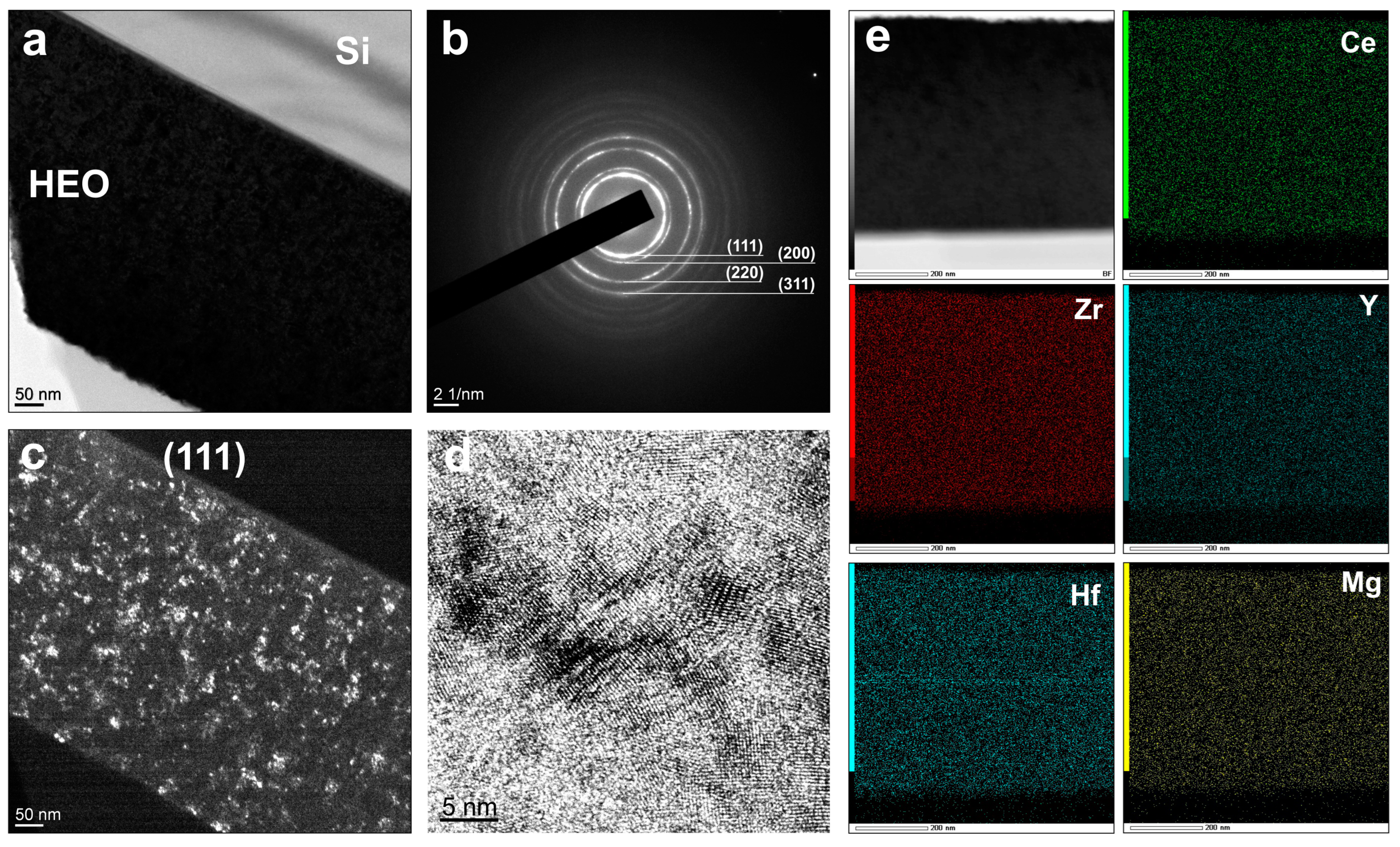
Table 1 shows the magnetron sputtering conditions and the corresponding molar compositions of the HfZrCeY(Mg)O films. MgO concentration strongly depends on the number of Mg discs in the erosion zone, while relative concentrations of other components are close to the equimolar composition with a deviation of less than 3 mol.%. The combination of the number of Mg discs in the CeY target with the variation of ICeYMg allows for the smooth tune of the elemental composition of HfZrCeY(Mg)O film.

3.1. Structure

XRD measurements of the synthesized films are presented in Figure 3. The HfZrCeY(Mg)O film with the low MgO concentration of 3.2 mol.% have the same structure as pure HfZrCeYO [10]. It is characterized by the simple cubic Fm-3m structure with four characteristic XRD peaks at 2θ = 29.28°, 34.42°, 49.08° and 58.92° attributed to (111), (200), (220) and (311) crystal orientations, respectively, as seen in the red line in Figure 3.
Further increasing of the MgO concentration up to 18.4 mol.% leads to the continuous elimination of the (200) peak without any changes at the mutual intensities of other peaks (Figure 3, blue line). At the higher MgO concentration (31.9 mol.%), one can detect the asymmetry of the (111), which can be given by the residual (200) crystallites or by the segregation of the hex-MgO (10-10) from the single crystal structure (Figure 3, yellow line). At the 34.5 mol.% of MgO, only a broad peak at 2θ = 31.02° attributed to the hex-MgO (10-10) can be detected (Figure 3, green line). With an additional elimination of the (220) and (311) peaks, this can be a result of the film amorphization. For all the synthesized films, no other peaks attributed to ternary oxide structures (such as Ce2Hf2O7 or Y2Zr2O7) can be detected.
For a deeper understanding of the MgO concentration effect, we used TEM measurements. Figure 4 and Figure 5 show the constituent element distribution for the low (3.2 mol.%) and the high (31.9 mol.%) concentration of the MgO, respectively. The films exhibited a homogeneous element distribution without any grain segregation for the whole range of the MgO concentrations. The TEM images of the HfZrCeY(Mg)O with a 3.2 mol.% MgO exhibited a nanocrystalline structure with a grain size of less than 50 nm (Figure 4).
The SAED patterns were acquired in the center of the HEO film to compare the phase structure with the XRD. The SAED and DF TEM measurements confirm the dominance of the (111) crystallites which are homogeneously distributed in the film thickness (Figure 4b,c). The crystallites with (200), (220) and (311) crystal orientations are also evenly distributed in the film thickness but have significantly lower crystallite size in comparison with (111). At the HRTEM image, one can detect a highly crystalline structure of HfZrCeY(Mg)O without a specific phase segregation or amorphous phase formation, which corresponds to the results of the X-ray diffraction analysis. The calculated interplanar spacing is 3.1 Å.
The HfZrCeY(Mg)O with a 31.9 mol.% MgO is also characterized by a nanocrystalline structure. Contrary to the XRD measurements, the selective area diffraction clearly shows a presence of the (200) orientation (Figure 5b). This result confirms the suggestion that an asymmetry of the (111) peak at XRD is given by the superposition of the (111) and (200) crystallite orientations rather than the MgO or ternary oxide separation. A distribution of crystallites with different orientations is noticeably higher in comparison with HfZrCeY(Mg)O with a low MgO content. The grain size for this composition is less than 20 nm. However, the HRTEM measurements still show the high crystallinity without an amorphous phase formation. The calculated interplanar for this composition spacing is 2.9 Å. A homogeneous elemental distribution confirms the fact of the Mg incorporation in an FCC structure of the high-entropy HfZrCeY(Mg)O.

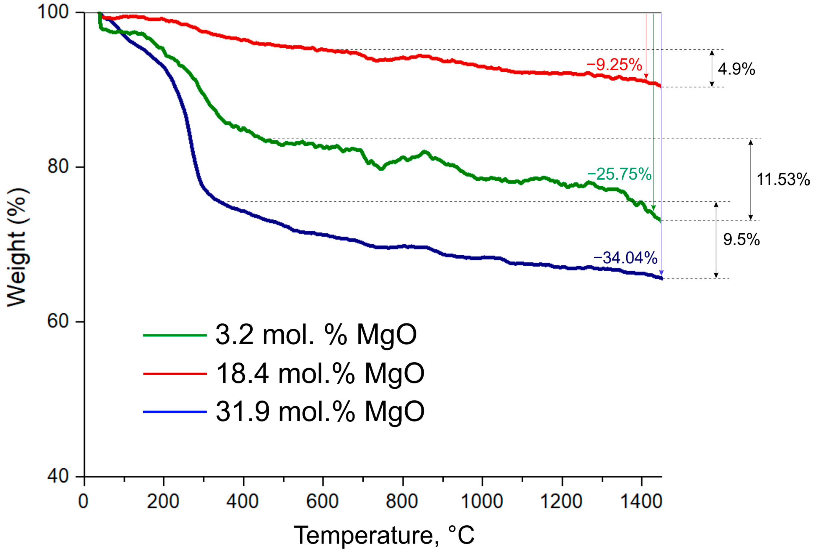
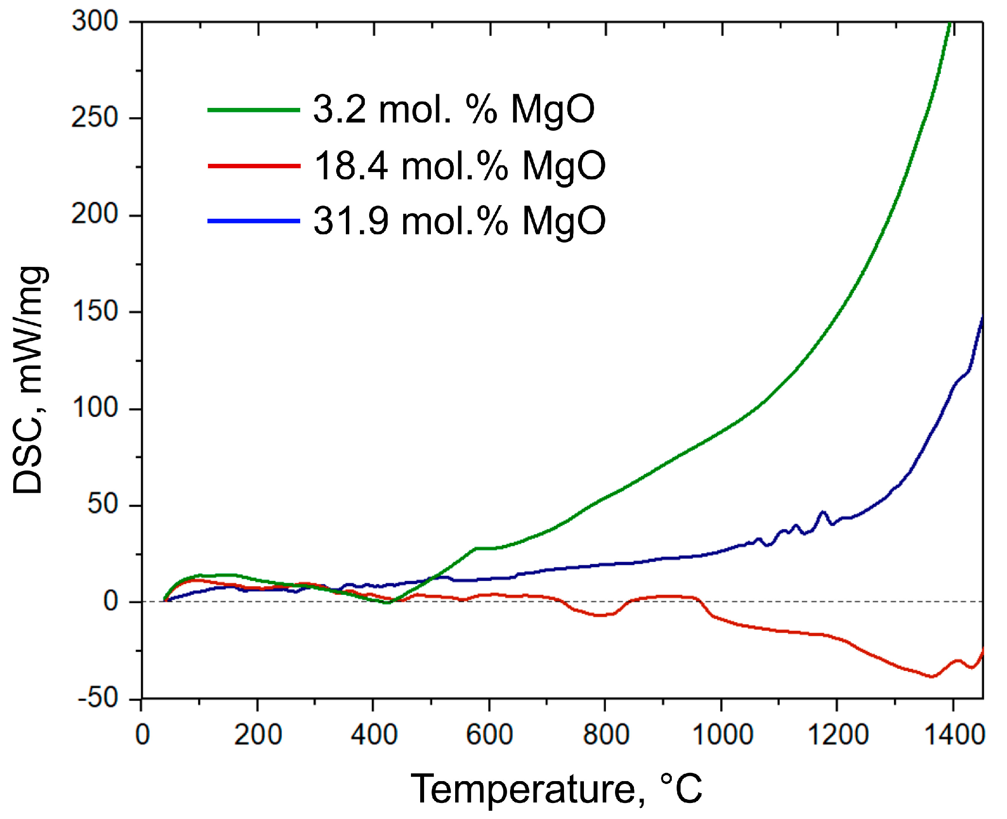
3.2. Thermal Properties

The thermal properties of the HfZrCeY(Mg)O films were measured via the TGA and DSC analysis from the RT up to 1450 °C. All the HfZrCeY(Mg)O films are characterized by an intensive mass loss from RT to ≈250 °C, as shown in Figure 6, and attributed to the water vapor loss due to the MgO and CeO2 hygroscopy [17].
A subsequent weight loss nonlinearly correlates with a MgO molar concentration. The maximum weight loss ≈11.53% occurs for HfZrCeY(Mg)O with 3.2 mol.% MgO. The corresponding DSC curve shows the exponentially increasing exothermic characteristic (Figure 7, green line). At the high MgO concentration (Figure 6 and Figure 7, blue line), the weight loss, excluding losses due to water desorption, is ≈9.5%. The HfZrCeY(Mg)O film is characterized by the less slope exponential exothermic characteristic in comparison with a HfZrCeY(Mg)O with 3.2 mol.% MgO. This composition shows the maximum water desorption, which correlates with a high MgO concentration. The minimum weight loss was measured for the close-to-equimolar HfZrCeY(Mg)O composition at 18.4 mol.% MgO (Figure 6, red line). This film is characterized by the lowest water desorption and the lowest weight loss ≈4.9% among all studied HfZrCeY(Mg)O compositions. Contrary to the non-equimolar films with high and low MgO concentrations, the HfZrCeY(Mg)O with 18.4 mol.% MgO exhibits close to zero heat flow at the range of RT—1000 °C and the endothermic characteristic at the range of 1000–1450 °C (Figure 7, red line).

3.3. Mechanical Properties

The mechanical properties of the HfZrCeY(Mg)O films are summarized in Table 2. The hardness H and effective Young’s modulus E* of HfZrCeY(Mg)O are proportionally decreased with an increase in MgO concentration. The maximum value of H = 20.4 GPa is close to the hardness of pure HfZrCeYO [13]. The hardness of the HfZrCeY(Mg)O equimolar composition (18.4 mol.% MgO) is about 25% lower in comparison with the equimolar HfZrCeYO [13]. The addition of Mg also reduces the resistance to crack formation of HfZrCeY(Mg)O due to the decrease in the H/E* ratio < 0.1 and elastic recovery We < 60% [18]. All of the synthesized HfZrCeY(Mg)O films exhibit relatively low compressive stress σ < −1.2 GPa, possibly due to the nanocrystalline structure.

4. Conclusions

Based on the measured data, we can conclude the following:
(1)
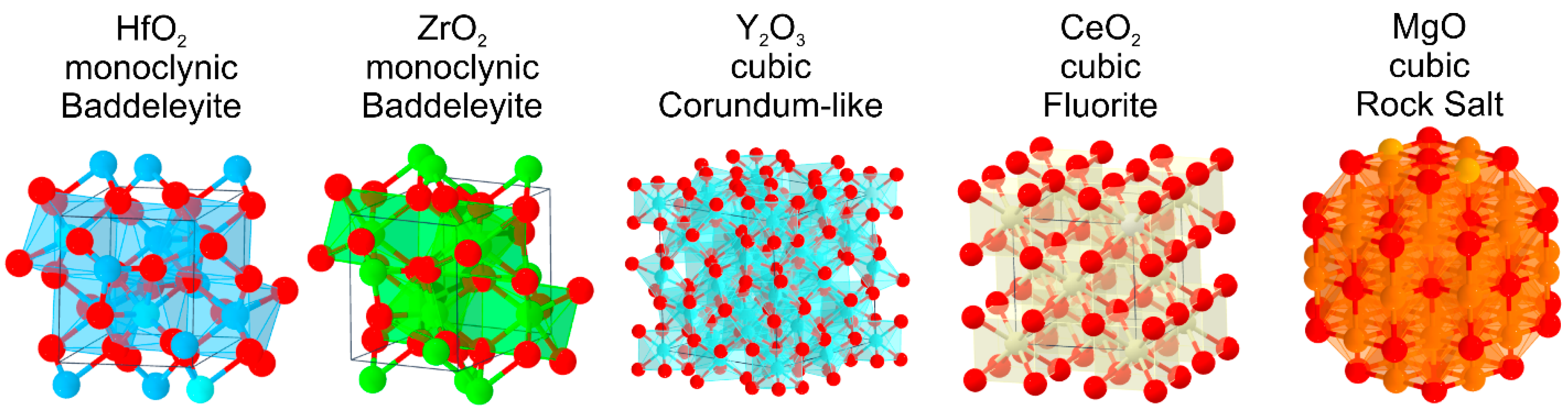
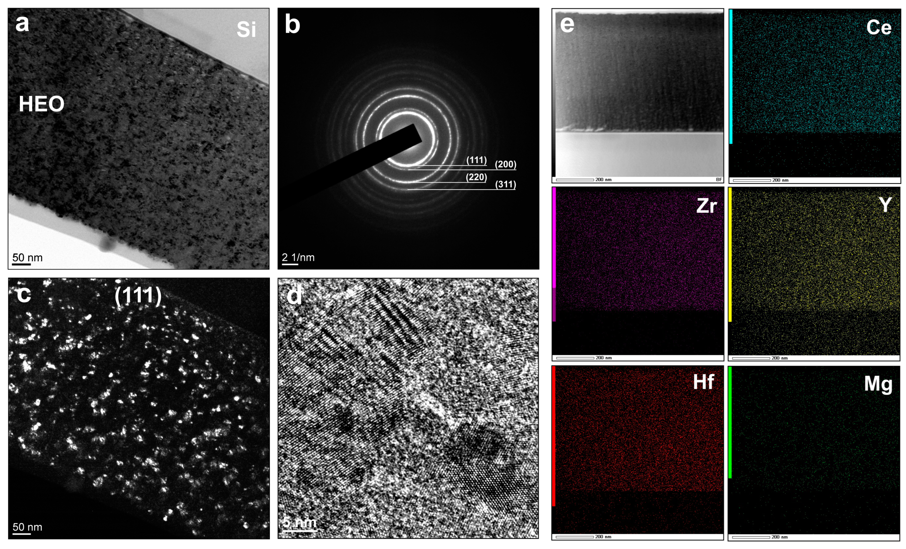
The HfZrCeY(Mg)O system forms a solid solution with the simple cubic (Fm-3m) structure without the formation of binary oxides and the absence of the phase separation.
(2)
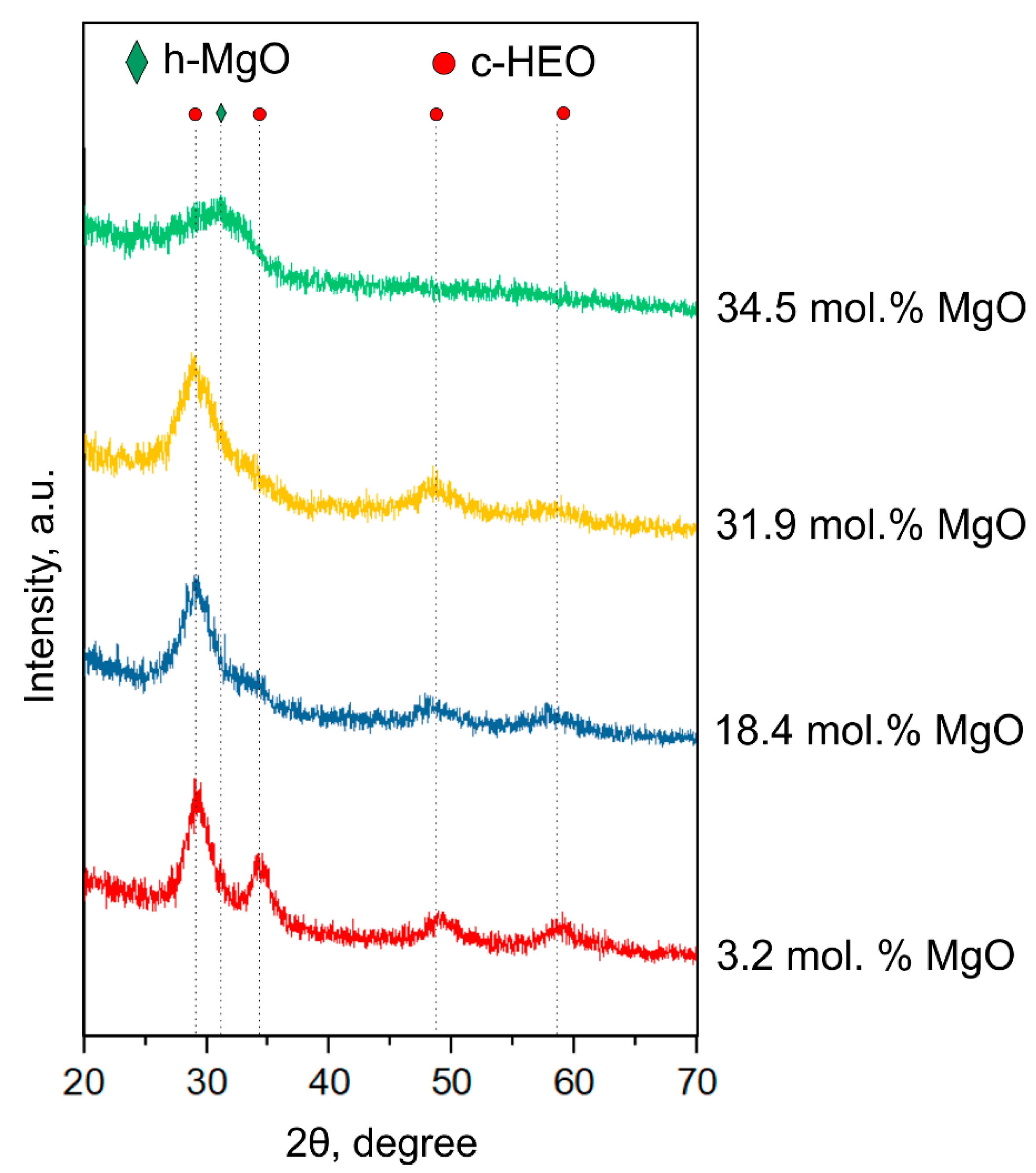
The HfZrCeY(Mg)O system maintains a single FCC crystalline structure up to the MgO concentration = 31.9 mol.% if other constituent oxides are taken in close to the equimolar composition.
(3)
The minimum weight loss at the heating from RT up to 1450 °C was measured for the close-to-equimolar HfZrCeY(Mg)O composition at 18.4 mol.% MgO.
(4)
The addition of MgO at the close-to-equimolar HfZrCeY(Mg)O composition enhances the thermal properties of HEO, but reduces the mechanical properties such as hardness and resistance to crack formation. The hardness of the close-to-equimolar HfZrCeY(Mg)O was 18.2 GPa.
(5)
The mechanical properties of the HfZrCeY(Mg)O proportionally decrease with the MgO concentration.

Author Contributions

Conceptualization, S.Z. and S.L.; methodology, S.Z. and A.G.; validation, S.Z., S.L. and A.G.; formal analysis, V.B. and A.M.; investigation, A.G. and A.M.; writing—original draft preparation, S.Z.; writing—review and editing, A.G., S.L. and A.M.; visualization, V.B.; supervision, S.L.; project administration, S.Z.; funding acquisition, S.Z. All authors have read and agreed to the published version of the manuscript.

Funding

This research was funded by the Russian Science Foundation, grant number 22-79-10069.

Institutional Review Board Statement

Not applicable.

Informed Consent Statement

Not applicable.

Data Availability Statement

Not applicable.

Conflicts of Interest

The authors declare no conflict of interest.

References

  1. Oses, C.; Toher, C.; Curtarolo, S. High-entropy ceramics. Nat. Rev. Mater. 2020, 5, 295–309. [Google Scholar] [CrossRef]
  2. Xiang, H.; Xing, Y.; Dai, F.-Z.; Wang, H.; Su, L.; Miao, L.; Zhang, G.; Wang, Y.; Qi, X.; Yao, L.; et al. High-entropy ceramics: Present status, challenges, and a look forward. J. Adv. Ceram. 2021, 10, 385–441. [Google Scholar] [CrossRef]
  3. Chen, J.; Zhou, X.; Wang, W.; Liu, B.; Lv, Y.; Yang, W.; Xu, D.; Liu, Y. A review on fundamental of high entropy alloys with promising high–temperature properties. J. Alloys Compd. 2018, 760, 15–30. [Google Scholar] [CrossRef]
  4. Miracle, D.B.; Senkov, O.N. A critical review of high entropy alloys and related concepts. Acta Mater. 2017, 122, 448–511. [Google Scholar] [CrossRef]
  5. Gild, J.; Zhang, Y.; Harrington, T.; Jiang, S.; Hu, T.; Quinn, M.C.; Mellor, W.M.; Zhou, N.; Vecchio, K.; Luo, J. High-Entropy Metal Diborides: A New Class of High-Entropy Materials and a New Type of Ultrahigh Temperature Ceramics. Sci. Rep. 2016, 6, 1–10. [Google Scholar] [CrossRef] [PubMed]
  6. Zhang, Z.; Zhu, S.; Liu, Y.; Liu, L.; Ma, Z. Phase structure, mechanical properties and thermal properties of high-entropy diboride (Hf0.25Zr0.25Ta0.25Sc0.25)B2. J. Eur. Ceram. 2022, 42, 5303–5313. [Google Scholar] [CrossRef]
  7. Pogrebnjak, A.D.; Postol’nyi, B.A.; Kravchenko, Y.A.; Shipilenko, A.P.; Sobol’, O.; Beresnev, V.M.; Kuz’menko, A.P. Structure and properties of (Zr-Ti-Cr-Nb)N multielement superhard coatings. J. Superhard Mater. 2015, 37, 101–111. [Google Scholar] [CrossRef]
  8. Moskovskikh, D.; Vorotilo, S.; Buinevich, V.; Sedegov, A.; Kuskov, K.; Khort, A.; Shuck, C.; Zhukovskyi, M.; Mukasyan, A. Extremely hard and tough high entropy nitride ceramics. Sci. Rep. 2020, 10, 19874. [Google Scholar] [CrossRef] [PubMed]
  9. Cong, L.; Li, W.; Wang, J.; Gu, S.; Zhang, S. High-entropy (Y0.2Gd0.2Dy0.2Er0.2Yb0.2)2Hf2O7 ceramic: A promising thermal barrier coating material. J. Mater. Sci. Tech. 2022, 101, 199–204. [Google Scholar] [CrossRef]
  10. Pak, A.Y.; Sotskov, V.; Gumovskaya, A.A.; Vassilyeva, Y.Z.; Bolatova, Z.S.; Kvashnina, Y.A.; Mamontov, G.Y.; Shapeev, A.V.; Kvashnin, A.G. Machine learning-driven synthesis of TiZrNbHfTaC5 high-entropy carbide. Npj Comput. Mater. 2023, 9, 7. [Google Scholar] [CrossRef]
  11. Gild, J.; Samiee, M.; Braun, J.L.; Harrington, T.; Vega, H.; Hopkins, P.E.; Vecchio, K.; Luo, J. High-entropy fluorite oxides. J. Eur. Ceram. Soc. 2018, 38, 3578–3584. [Google Scholar] [CrossRef]
  12. Li, Z.; Zheng, J.; Zhang, W.; Zheng, Y.; Zhao, W.; Xue, L.; Yang, F.; Chen, H. A Promising High-Entropy Thermal Barrier Material with the Formula (Y0.2Dy0.2Ho0.2Er0.2Yb0.2)3Al5O12. Materials 2022, 15, 8079. [Google Scholar] [CrossRef] [PubMed]
  13. Zenkin, S.; Gaydaychuk, A.; Mitulinsky, A.; Linnik, S. Tailoring of optical, mechanical and surface properties of high-entropy Hf-Zr-Ce-Y-O ceramic thin films prepared by HiPIMS sputtering. Surf. Coat. Technol. 2022, 433, 128164. [Google Scholar] [CrossRef]
  14. Fahrenholtz, W.G.; Hilmas, G.E. Ultra-high temperature ceramics: Materials for extreme environments. Scr. Mater. 2017, 129, 94–99. [Google Scholar] [CrossRef]
  15. Duwez, P.; Odell, F. Phase Relationships in the System Zirconia—Ceria. J. Am. Ceram. Soc. 1950, 33, 274–283. [Google Scholar] [CrossRef]
  16. Yanagida, H.; Koumoto, K.; Miyayama, M. The Chemistry of Ceramics; John Wiley & Sons: Hoboken, NJ, USA, 1996; ISBN 0-471-95627-9. [Google Scholar]
  17. Wetteland, C.L.; Sanchez, J.D.J.; Silken, C.A.; Nguyen, N.-Y.T.; Mahmood, O.; Liu, H. Dissociation of magnesium oxide and magnesium hydroxide nanoparticles in physiologically relevant fluids. J. Nanopart. Res. 2018, 20, 1–17. [Google Scholar] [CrossRef]
  18. Musil, J. Hard nanocomposite coatings: Thermal stability, oxidation resistance and toughness. Surf. Coat. Technol. 2012, 207, 50–65. [Google Scholar] [CrossRef]
Figure 1. Structure of the constituent binary oxides at normal conditions.
Coatings 13 00917 g001
Figure 2. A scheme of the experiment. Mg concentration in the HfO2–ZrO2–Y2O3–CeO2 system was controlled by the number of the Mg discs in the erosion zone of the CeY magnetron.
Coatings 13 00917 g002
Figure 3. XRD patterns of the high entropy HfZrCeY(Mg)O films in dependence on the MgO molar concentration.
Coatings 13 00917 g003
Figure 4. TEM images of the high entropy HfZrCeY(Mg)O film with the 3.2 mol.% MgO concentration (a) with the corresponding SAED patterns (b); DF TEM for (111) orientation (c) and HRTEM of the selected area (d); EDS mapping of the constituent elements (e).
Coatings 13 00917 g004
Figure 5. TEM images of the high entropy HfZrCeY(Mg)O film with the 31.9 mol.% MgO concentration (a) with the corresponding SAED patterns (b); DF TEM for (111) orientation (c) and HRTEM of the selected area (d); EDS mapping of the constituent elements (e).
Coatings 13 00917 g005
Figure 6. TGA analysis of the HfZrCeY(Mg)O in dependence on the molar MgO concentration.
Coatings 13 00917 g006
Figure 7. DSC curves for the HfZrCeY(Mg)O in dependence on the molar MgO concentration.
Coatings 13 00917 g007
Table 1. Deposition conditions and the resulting compositions of the HfZrCeY(Mg)O films.
Film №UHfZr
[V]
IHfZr
[A]
UCeYMg
[V]
ICeYMg
[A]
Number
of
Mg Discs
HfO2
[mol.%]
ZrO2
[mol.%]
CeO2
[mol.%]
Y2O3
[mol.%]
MgO
[mol.%]
138023202123.125.824.123.83.2
237023152319.222.021.319.118.4
338023002618.221.712.515.731.9
437523303615.217.914.817.634.5
Table 2. Mechanical properties of the HfZrCeY(Mg)O films in dependence on the MgO content. Here, H is hardness, E* is effective Young’s modulus, We is elastic recovery and σ is film stress.
Film №MgO
[mol.%]
H
[GPa]
E*
[GPa]
H/E*We
[%]
σ
[GPa]
13.220.4198.70.10365−1.2
218.418.2193.40.09462−0.8
331.916.7185.70.0957−0.9
434.512.9176.20.07355−0.5
Disclaimer/Publisher’s Note: The statements, opinions and data contained in all publications are solely those of the individual author(s) and contributor(s) and not of MDPI and/or the editor(s). MDPI and/or the editor(s) disclaim responsibility for any injury to people or property resulting from any ideas, methods, instructions or products referred to in the content.

