
Mechanical Behaviour of Hard Chromium Deposited from a Trivalent Chromium Bath


1
Laboratoire Génie de Production, Ecole Nationale d’Ingénieurs de Tarbes, INPT, Université de Toulouse, 47 Av. d’Azereix, 65016 Tarbes, France
2
Mecaprotec Industries, 34 Boulevard de Joffrery, 31600 Muret, France
*
Author to whom correspondence should be addressed.
Coatings 2022, 12(3), 354; https://doi.org/10.3390/coatings12030354
Submission received: 31 January 2022
/
Revised: 1 March 2022
/
Accepted: 4 March 2022
/
Published: 7 March 2022
(This article belongs to the Topic Inorganic Thin Film Materials)
Abstract
:In view of new environmental directives, hexavalent chromium baths can no longer be used to electroplate thick hard chromium deposits. To meet these industrial and environmental challenges, deposits are developed from trivalent chromium electrolytes. Cr(III) coatings are usually studied from the point of view of the use properties and hardness, but their intrinsic properties remain widely unknown. The novelty of this work consists in the mechanical characterisation of these coatings. Properties such as hardness, stiffness, yield strength, and toughness of trivalent chromium deposits are determined by combining instrumented hardness tests, in situ FEG–SEM observations, and finite element simulations. These are explained according to the microstructure of the deposits, which is determined by scanning electron microscopy and X-ray diffraction. Their composition was characterised by glow discharge spectrometry. The structure characterisation deposits showed a more severely fractured coating of trivalent chromium than in the case of hexavalent chromium. Non-post-treated trivalent chromium deposits have a higher hardness (13 ± 1.7 GPa) and yield strength (5 GPa) than hexavalent chromium deposits. However, their stiffness (191 ± 13 GPa) and toughness (1.37 ± 0.13 MPa√m) are lower. Its mechanical behaviour is elastofragile. These differences in mechanical properties can be explained by the amorphous structure of the deposits and their high carbon content.
1. Introduction
Chromium electroplating coatings have been used in a variety of engineering applications or simply for aesthetic purposes since the early 20th century [1]. The process was first commercialised and patented in 1926 with bath chemistry of chromic acid and sulphuric acid, mainly based on the work of Fink and Eldridge in 1924. This surface treatment is essential, in particular, because of its ability to obtain a chromium deposit with remarkable antiwear and anticorrosion properties, its ease of production, and its low production cost. It can be found in the aeronautics, space, automotive, and arms industries [2,3,4]. Although the hard chromium coating does not present any particular danger, its production raises serious issues. Indeed, this process uses a chromium trioxide-based bath that is now listed in Annex XIV of the European REACH regulation (Registration, Evaluation, Authorization of Chemicals), similar to all hexavalent chromium-based substances that are classified as carcinogenic, mutagenic, and reprotoxic [5]. In order to definitively eliminate hexavalent chromium deposits, the main lines of research are [1,6,7] electrolytic composite deposits, vacuum deposits, thermal spray deposits, or chromium deposits from trivalent chromium baths.
Unlike the preparation of hard chromium coatings based on hexavalent chromium, which is very well known at the present time, the preparation of these same deposits of trivalent chromium is still at the development stage. The formulation of the electrolyte used is not yet agreed upon in the literature; many formulations are used by different authors [8,9,10,11]. This adds an additional difficulty to the identification of the mechanisms involved in the growth of the deposits and their characterisation. Depositing chromium from Cr(III)-containing electrolyte leads to coatings with lower crystallinity. In addition, their thickness is small, well below 100 microns [8]. These main differences between coatings made from either Cr(III) or Cr(VI) ions can be explained by their different growth patterns [12,13]. In aqueous solution, Cr(III) forms a stable [Cr(H2O)6]3+ complex, which implies a different reduction mechanism than in Cr(VI) solutions. Thus, the use of Cr(III) solutions requires the introduction of a complexing agent into the electrolyte such as formate (HCOO−) [14], oxalate (HOOC-COO−) [15], acetate [16], glycinate (C2H4NO2) [17], or carbamate (CO2NH2) [8].
The mechanical properties of trivalent chromium deposits are still poorly understood. Only hardness data are given, as well as usage properties such as wear or corrosion resistance. Electrolytic deposits made from trivalent chromium have a Vickers hardness of over 800 HV overall, which is slightly higher than the values for deposits made from hexavalent baths [18,19,20,21,22]. A large disparity in published hardness values is found for untreated (200 to 1400 HV) and post-treated (up to 1800 HV) trivalent chrome deposits. This disparity can therefore be explained by the influence of several factors: the test device and measurement methodology, the different bath chemistries used, the deposition and bath temperature parameters, or the heat treatment parameters. According to the properties of interest of these deposits, the wear resistance of trivalent coating is similar to the hexavalent one [23], and better than other alternatives such as PVD chromium deposits [24]. In addition, some authors show that trivalent chromium deposits could be improved by adding charges (aluminium oxide) or bath chemistry [25,26,27]. The corrosion resistance properties of trivalent deposits seem similar or even better than hexavalent chromium coating [4]. However, the structure of trivalent chromium, showing through-thickness cracks, strongly limits its corrosion resistance [3]. The mechanical behaviour of chromium deposits is not very well specified. Moreover, no data on yield strength or even toughness are given in the literature concerning trivalent chromium deposits. These data are necessary to understand the microcracking of these deposits and their mechanical resistance to wear. While many techniques and tests exist to determine fracture toughness for solid materials, it is more difficult to apply them to characterise the toughness of thin films. Nevertheless, several approaches specific to thin films have been developed. Among these approaches, the most widely used are scratch and indentation tests for hard coatings [28]. Methods based on the machining of microgeometries using a focused ion beam (FIB) have been developed [29,30,31,32]. This allows only the deposit to be stressed. There are several geometries commonly used: the single notched beam bending [29,33], the double cantilever [34] (very close to the geometry classically used in the determination of the toughness of solid parts), or the indentation of a pillar [35].
As we pointed out previously, hardness alone does not provide a detailed understanding of the mechanical behaviour of coatings. Therefore, in this study, in addition to hardness, we propose for the first time to characterise the mechanical behaviour of chromium deposits electroplated in electrolytes containing trivalent chromium ions. This work confirmed the higher hardness values of these new deposits compared to reference chromium deposits obtained in hexavalent chromium baths. They also allowed the stiffness, yield strength, and toughness of these deposits to be specified in comparison with hexavalent chromium deposits.
2. Materials and Methods
2.1. Materials
The chromium coatings were developed by direct current electrodeposition on either 1.0402 unalloyed steel substrate or 1.6747 low alloyed steel. The plates used have a thickness of 1 mm. To establish a basis for comparison with the properties of coatings currently used in the aerospace industry, hexavalent chromium deposits were obtained from an aqueous solution containing chromium trioxide (CrO3) and sulphuric acid (H2SO4).
The trivalent chromium deposits were electrodeposited in electrolytes containing trivalent chromium salt (CrCl3, H2O), glycine, sodium chloride (NaCl), and aluminium chlorohydrate (AlCl3, 6H2O). The deposits were prepared in 85 L tanks. The pH of the solution varied between 0 and 2. All the coatings were produced at a deposition rate of one micron per minute. After elaboration, a thermal degassing post-treatment at 190 °C was carried out for 3 h in order to limit the influence of hydrogen embrittlement.
2.2. Methods
The samples were previously polished by abrasion to a mirror finish to limit surface effects, without significantly reducing the thickness. The polishing process began with SiC paper from a size up to 4000 and followed by diamond polishing from 3 to 1/4 µm. Cross-sectional micrography are also operated by successive polishing.
The mechanical behaviour of the trivalent chromium deposits was determined by Brinell indentation. The tests were carried out using an instrumented hardness tester (Zwick ZHU/zwickiLine +, Zwick/Roell, Paris, France). Two Brinell indenters were used, a 1 mm diameter ball and a 5 mm diameter ball. A test series was carried out with maximum applied loads of 5, 10, 50, 200, 300, 500, 750, and 1000 N. The determination of the mechanical behaviour of the deposits was based on the interpretation of the load–unload curves given by the hardness machine and postmortem observations of the indentations by classical optical microscopy (PMG3 microscope, Olympus France SAS, Rungis, France) and 3D optical microscopy (VHX-950F 3D microscope, Keyence France SAS, Bois-Colombes, France).
Hardness and stiffness measurements were carried out using the nanoindentation system (Nano Indenter® XP, MTS, Paris, France) equipped with a Berkovich indenter. The penetration speed was set at 0.05 s−1. The measurements were carried out at room temperature at an imposed depth of 2000 nm. The results presented for each coating are based on an average of 50 tests. In addition, for each test, an average stiffness and hardness value were determined for depth values between 500 and 900 nm using the CSM (continuous stiffness measurement) mode available on this equipment [36]. For the stiffness calculation, Poisson’s ratio value of 0.21 was taken [37]. The samples were previously polished to a mirror-polished state to limit surface effects, without significantly reducing the thickness. No data were retained below 500 nm to avoid the influence of polishing or surface roughness. The maximum limit of 900 nm corresponds to the maximum load for which we have no cracks in the layer.
The yield strength was determined by inverse methods. We used the experimental force–displacement curves to fit a numerical simulation model. The Berkovich indentation at low load was used to avoid cracking as much as possible. The method used was inspired by the work of Sebastiani et al. [35]. A trial-and-error method was used to calibrate the curves.
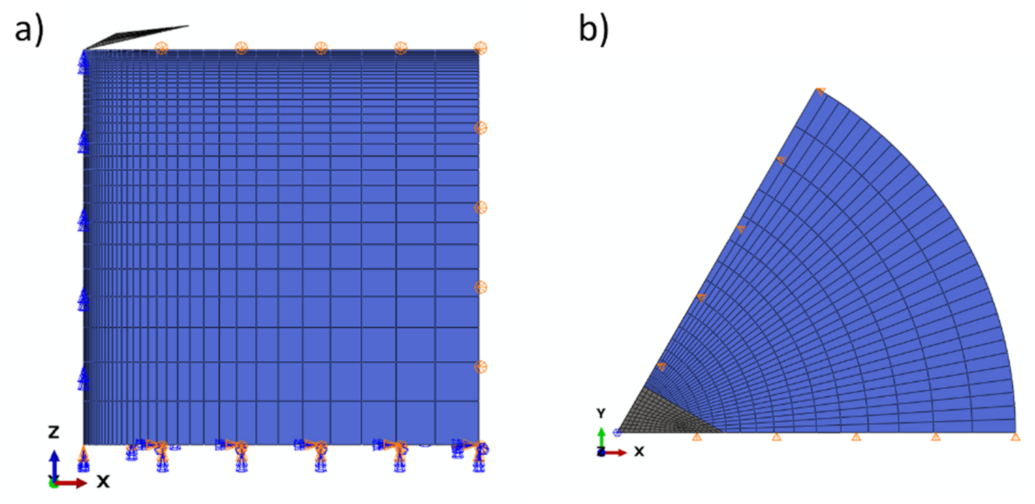
The simulation of the loading/unloading curves was modelled using Abaqus® FEM software (Abaqus/CAE 2021). A three-dimensional model consisting of a rigid pyramidal Berkovich indentor in contact with a deformable cylinder of sufficient size to neglect the impact of boundary conditions was implemented. Owing to the symmetries of the problem, only one-sixth of the geometry was modelled (Figure 1). C3D8 linear brick elements were used to model the layer. The indentor is described as rigid. The brittle behaviour of our material was modelled by an elastic perfectly plastic law according to the work of Sebastiani et al. [35].
The toughness of the chromium deposits was determined by an indentation test performed on FIB-machined micropillars. Sébastiani et al. established a simple relationship between the critical load at failure, the radius of the pillar, and a coefficient that was calibrated using a finite element simulation (Equation (1)):
where KIC is the (mode 1) toughness, γ a dimensionless coefficient from the simulation, Pcrit the critical load, and R is the radius of the pillar. The advantage of this technique is that it is not necessary to measure geometry or crack size after the test. Furthermore, it has been shown that from a height to diameter ratio greater than 1, residual stresses are almost entirely relaxed in the upper part of the pillar [38]. This geometry strongly limits the potential influence of the substrate by locating the stresses at the extreme surface. The dimensionless coefficient was set to 0.3 as defined by Sébastiani et al. [35]. The critical load (Pcrit) was obtained using the MTS Nano Indenter® XP system with a Berkovich indenter. The pillars were made by FIB machining (Helios 600i, FEI France, Paris, France). The diameter of the pins is 7 microns with a pin height-to-diameter ratio of 1. The results presented for each coating are based on an average of 3 to 7 trials.
3. Results
3.1. Microstructure
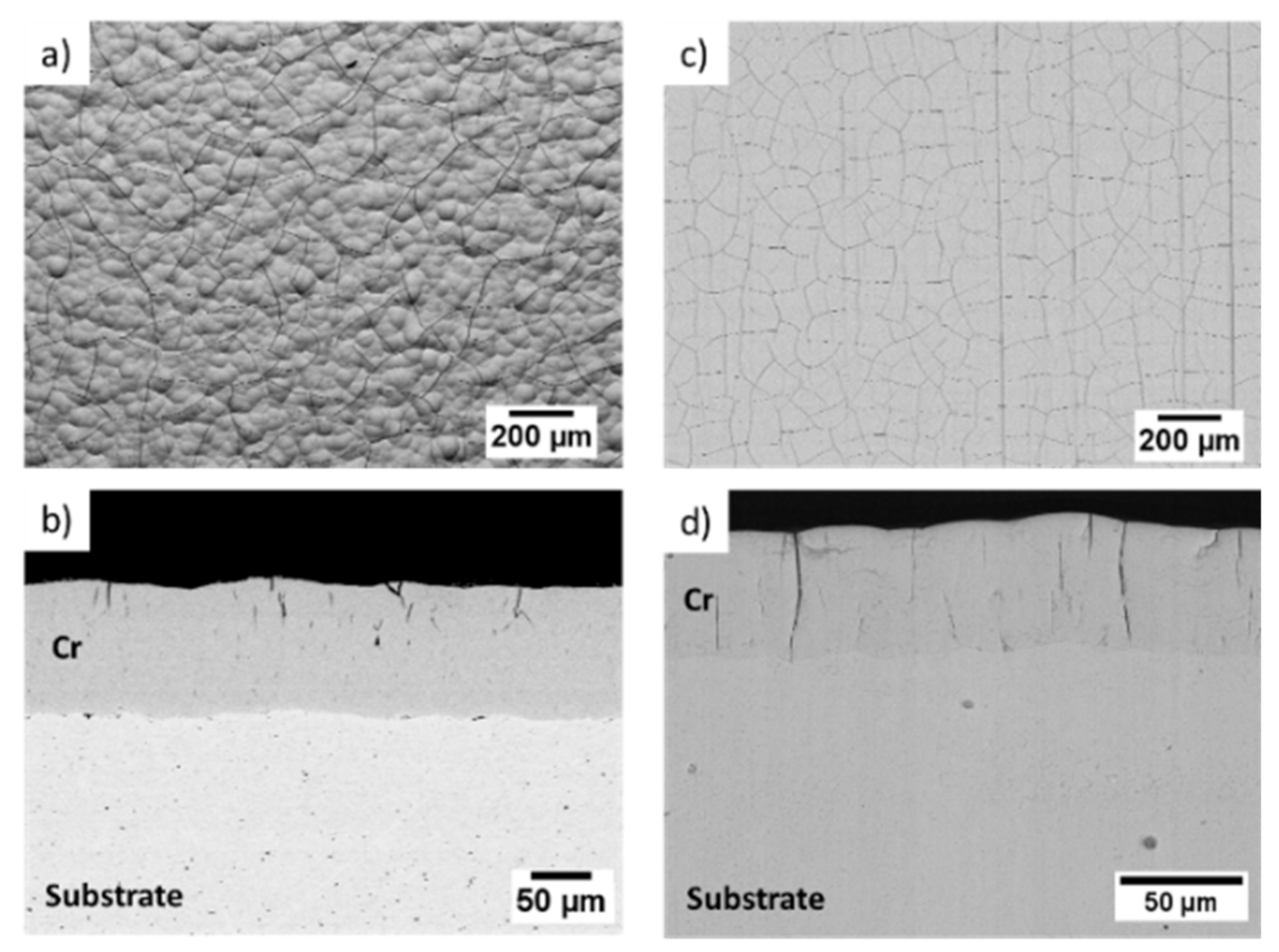
The morphology of the coatings was examined both in surface and cross-section. Figure 2 compares the resulting SEM micrographs of the hexavalent and trivalent chromium deposits.
The surface of the hexavalent chromium deposits shows a more pronounced nodular morphology than the trivalent chromium deposits (Figure 2a,c). Whatever the type of deposit, a network of cracks is observed on the surfaces. The cross-sectional observations show the presence of multiple cracks distributed throughout the thickness of the deposit (Figure 2b,d). In the case of trivalent chromium, we also observe the presence of cracks crossing the entire thickness of the deposit (Figure 2d).
3.2. Mechanical Behaviour
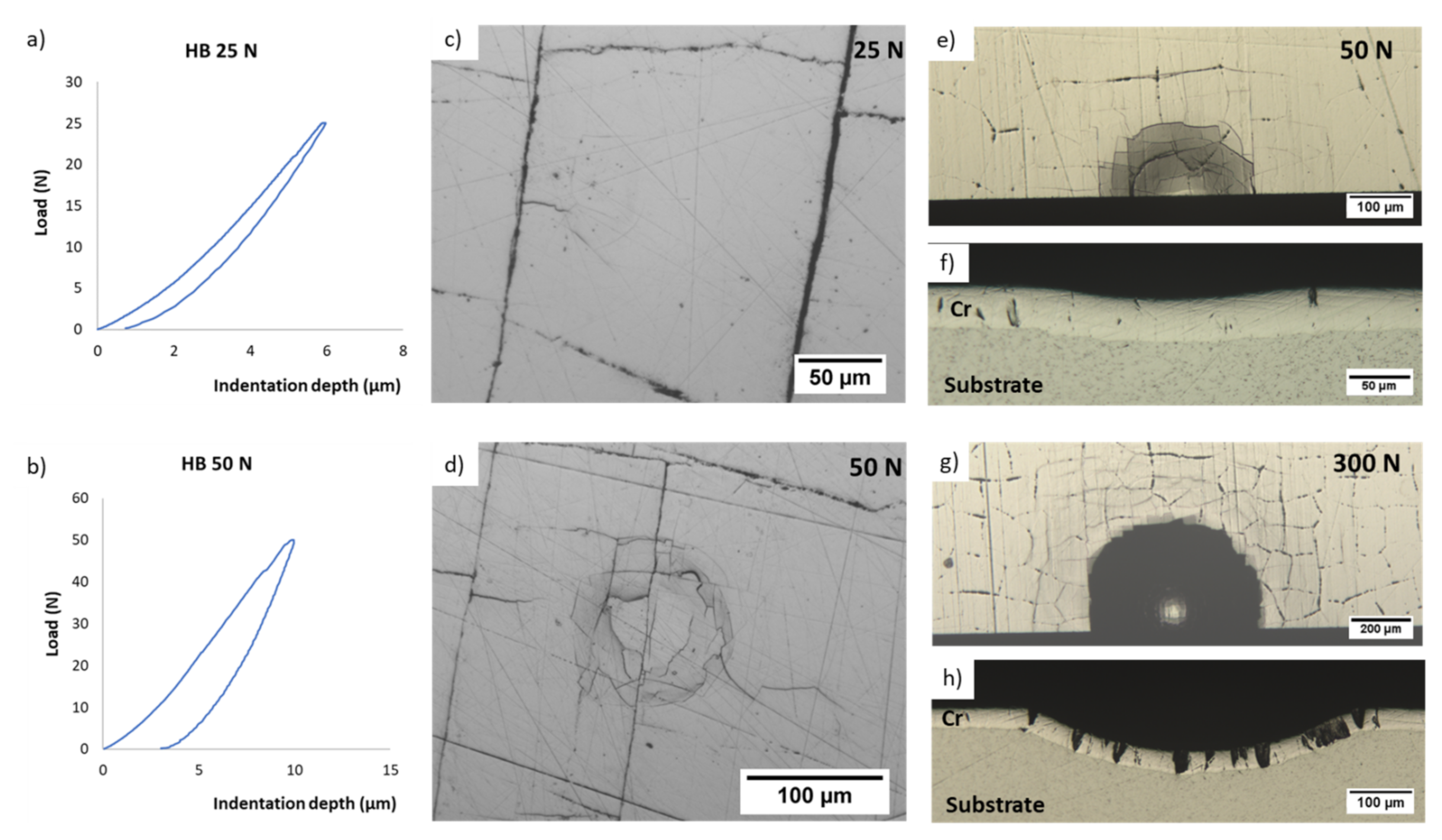
The identification of the mechanical behaviour of trivalent chromium coatings was determined from instrumented Brinell indentation tests. The charge–discharge curves and indentation observations for beads of 1 mm diameter and a deposit thickness of 100 microns are shown in Figure 3a–d. For low applied loads, residual indentations are not visible (Figure 3c). They are discernible for a load of 50 N for tests performed with the 1 and 5 mm ball. The residual depth increases with the applied load (Figure 3b).
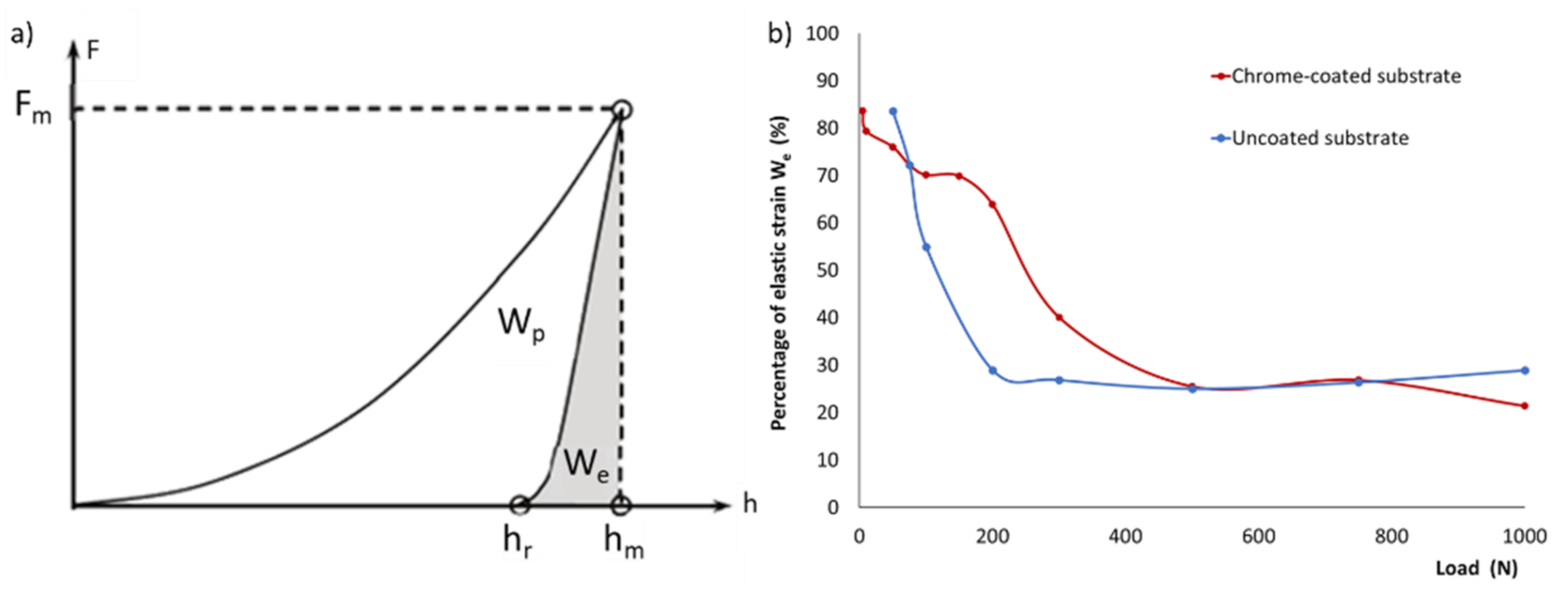
Instrumented Brinell hardness tests were carried out on a trivalent chromium-coated substrate and on an uncoated substrate. The plastic and elastic strain works were determined for each test from the measurement of the areas under the curves by the trapezoidal rule (Figure 4a). In order to determine the mechanical behaviour of the deposits (elastofragile or elastoplastic) during indentation, the percentage of elastic deformation is, of course, very high for very low loads (load applied less than or equal to 50 N) and low for high loads whatever the sample. However, the percentage of elastic work decreases very quickly for the uncoated substrate (elastoplastic behaviour) while it remains significant for the coated substrate. The percentage of elastic work decreases slightly up to an applied load of 200 N for the coated sample and more significantly thereafter. A stabilisation of the ratio at a value of 26% is observed at loads higher than 500 N, corresponding to the substrate uncoated for the same load level. This first result seems to show that the deformation of the Cr (III) deposit is mainly elastic while the substrate deforms elastically for low loads and then plastically. Further tests were carried out with a 5 mm diameter ball on deposits that were 40 microns thick (Figure 3e–h). No decrease in deposit thickness is observed in the indented area. Only an increase in the cracking rate is recorded on the indentation flank with the applied load. It would therefore appear from these results that the substrate behaves in an elastoplastic manner and the trivalent chromium coatings behave in an essentially elastofragile manner, under indentation solicitation. In order to clarify this elastofragile behaviour, the mechanical properties of trivalent chromium deposits were determined.
3.3. Mechanical Properties
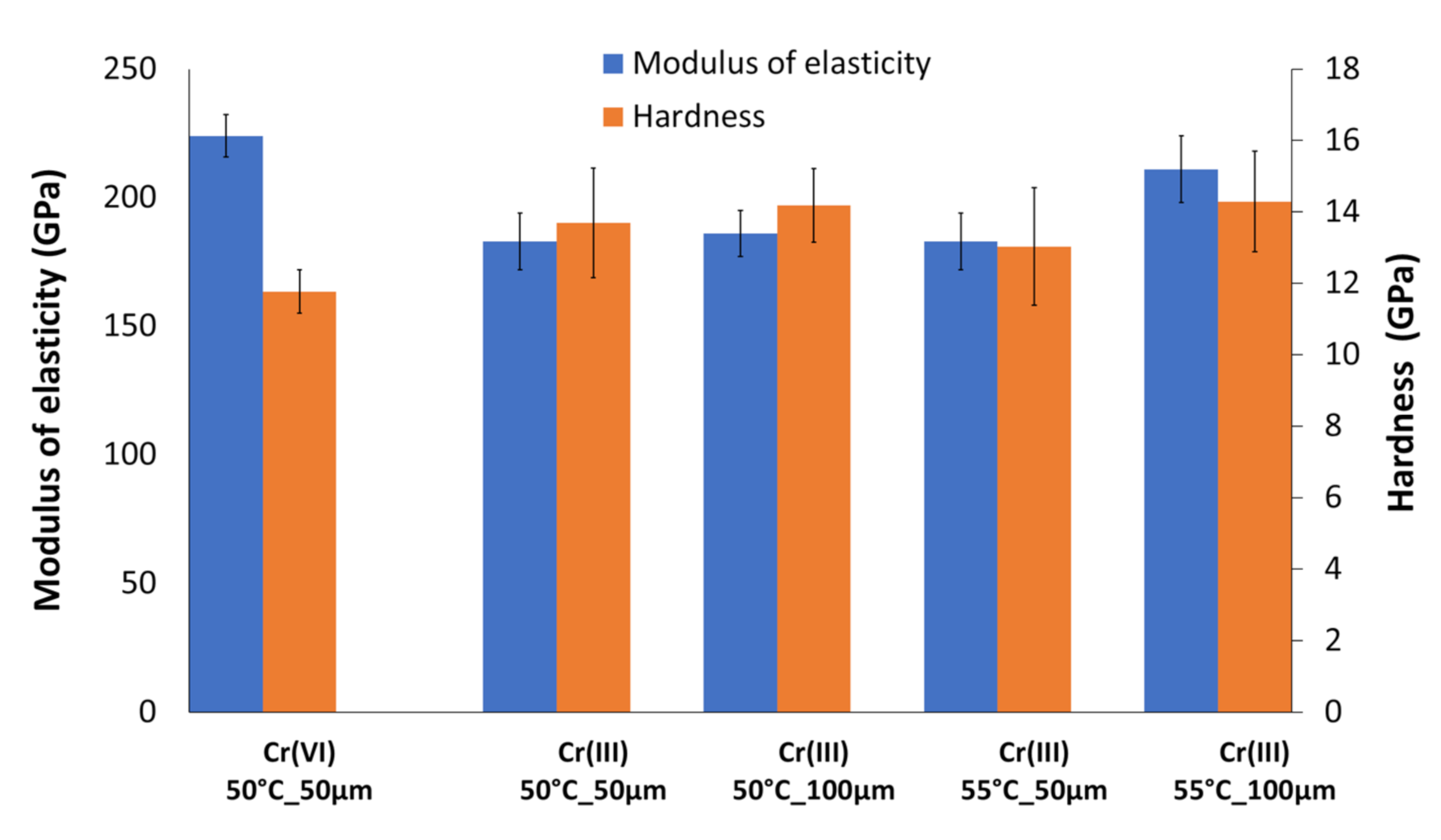
3.3.1. Hardness and Stiffness
The hardness and stiffness values of trivalent chromium deposits produced at various bath temperatures and thicknesses are given in Figure 5. These are compared with the mechanical properties of a hexavalent chromium deposit. The modulus of elasticity is relatively stable across the trivalent chromium formulations, with a minimum at 182 GPa, a maximum at 211 GPa, and an average of 191 ± 13 GPa. A drop of about 15% is observed between the reference hexavalent chromium deposit (224 ± 8 GPa) and the average of the values obtained for trivalent chromium deposits. Concerning hardness, the trivalent chromium deposits are harder than the reference deposit. Their hardness varies between 13.03 and 14.29 GPa. The thickness of the layers does not appear to have a significant effect on the measured properties (Figure 5). The standard deviations for the calculated H and E values of the Cr(III) coating are higher than those of the Cr(VI) coating.
3.3.2. Yield Strength
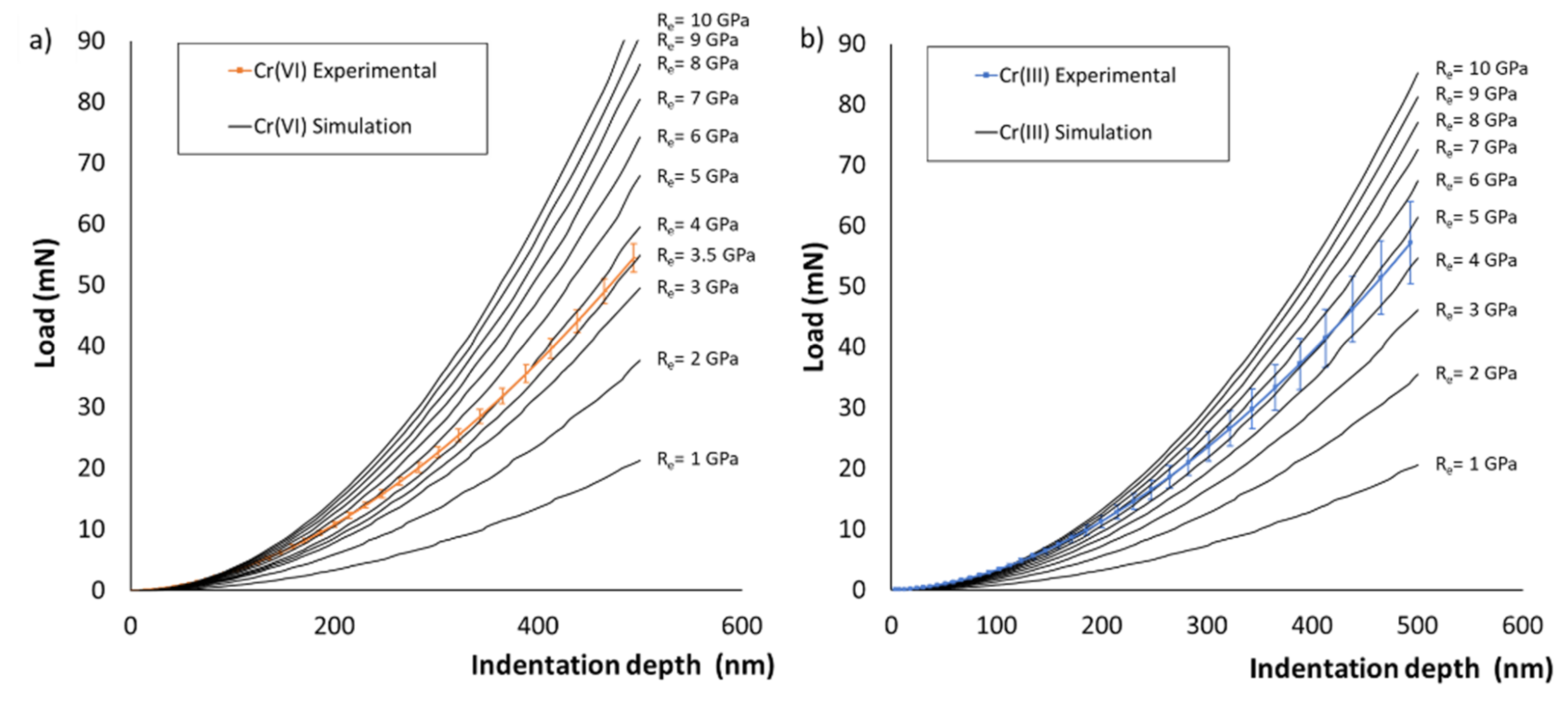
Figure 6 shows the results of finite element simulations of the nanoindentation tests to determine the yield strength of the deposits. The loading curves obtained by simulation for yield strength values between 1 and 10 GPa are compared to the experimental loading curves. The loading curves obtained by simulation with yield stress values of 3.5 GPa for the hexavalent chromium deposit and 5 GPa for the trivalent chromium deposit are the closest to the experimental loading curves. These results are therefore selected for each coating.
3.3.3. Toughness
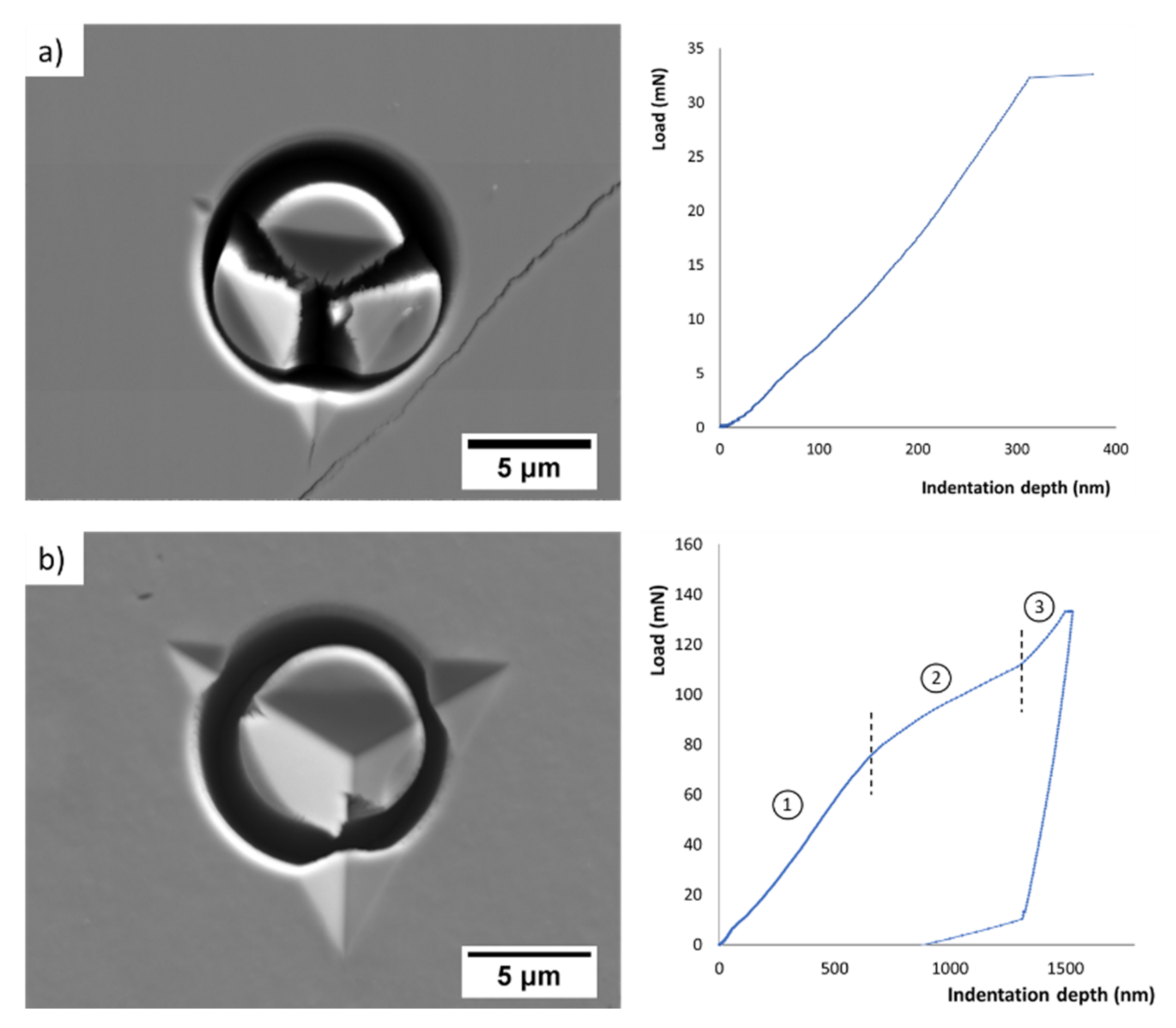
The fracture surfaces of micropillars machined from trivalent and hexavalent chromium coatings and the loading curves during the indentation tests are shown in Figure 7. The micropillars obtained from trivalent chromium deposits fracture at a load of between 30 and 35 mN. In contrast, micropillars machined from hexavalent chromium deposits do not fracture during indentation tests. Their loading curve consists of several sections. The first section corresponds to the compression of the micropillar only. The indenter is always in contact with the upper surface of the pillar. The second section of the curve corresponds to a lower loading rate. The indenter continues to move vertically, but part of the tip is in the gap around the pillar, indeed it exceeds the area of the micropillar. Finally, the third part of the curve corresponds to an increase in the loading rate induced by the contact of the indenter with the rest of the deposit beyond the gap.
The toughness values of the hexavalent and trivalent chromium deposits are 1.37 ± 0.13 and 5 MPa√m, respectively. These values are low for metallic materials. They seem to reinforce the hypothesis of a purely elastofragile behaviour without a plasticity domain of trivalent chromium deposits in particular. The value of the toughness calculated for the hexavalent chromium deposit is a minimum value because it corresponds to a maximum load applied to the indenter before it comes in contact with the rest of the deposit, thus preventing the pillar from cracking.
4. Discussion
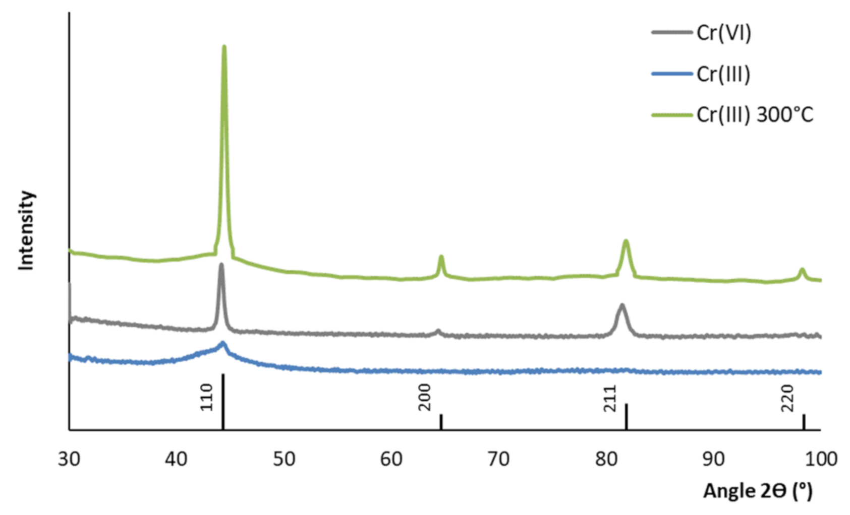
The lower stiffness value of the trivalent chromium deposits compared to the reference hexavalent chromium deposit can be explained by the difference in microstructure between the two deposits. Hexavalent chromium generally has a fine-grained polycrystalline structure, whereas trivalent chromium has an amorphous and/or nanocrystalline structure [39]. To analyse the structure of our coatings, X-ray diffraction analyses were performed using a diffractometer (X’Pert MRD, Panalytical France, Paris, France, λKα = 0.154056 nm). The trivalent chromium deposits show a single very broad peak at an angle of 44.392° (Figure 8). These deposits are therefore considered amorphous (or possibly nanocrystalline). In contrast, hexavalent chromium shows distinct diffraction peaks, typical of a crystalline material. By studying the position of the peaks and their intensities, the body cubic centred structure corresponding to JCPDS sheet no. 060694 was identified for the hexavalent chromium deposit.
The lattice parameter of the BCC structure is 2.883 nm. In the literature, an increase in mechanical properties and in particular in the modulus of elasticity is classically observed following the crystallisation of an amorphous bulk material [40,41]. Alexis observed the same phenomenon on nickel–phosphorus deposits [42]. Willis and Hammond show that a heat treatment between 200 and 350 °C leads to the recrystallisation of a trivalent chromium deposit [39]. We therefore carried out a heat treatment at 300 °C for one hour on the trivalent chromium deposit before analysing its structure and then measuring its rigidity. The trivalent chromium deposit is crystalline after heat treatment. The structure is BCC with a crystal parameter of 2.883 nm (Figure 8) [43]. Its stiffness value increased by 40% (251 ± 14 GPa). It is therefore comparable to that of the hexavalent chromium deposit (224 ± 8 GPa).
The large standard deviation observed in the hardness and stiffness measurements can be explained by the amorphous structure of the trivalent chromium deposits. The phenomenon of “pop-ins” that appears on the load–displacement curves obtained by nanoindentation is linked to the nucleation and propagation of shear bands in amorphous materials [44]. In addition, the amorphous material is also sensitive to the indentation size effect (ISE) [45]. The increase in defect concentration with increasing indentation depth during nanoindentation causes a softening of the deformation, which resulted in an indentation size effect. Finally, interstitial atoms such as carbon influence the pop-in behaviour by blocking pre-existing dislocations. This phenomenon is very similar to the Lüders deformation obtained in a macroscopic tensile test. The unlocking of dislocations blocked by carbon atoms (Cottrell atmospheres) can also lead to pop-in [46].
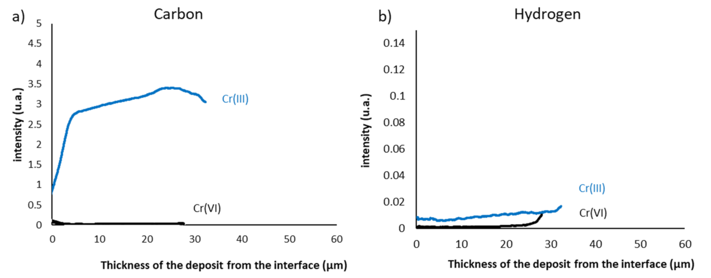
A minimum value of 5 MPa√m was estimated for the hexavalent chromium deposit through the micropillar indentation test. This value is of the same order of magnitude as that given in the literature. Durut characterised this value from the volume of the plasticised zone located at the crack tip. He estimates the toughness of these hexavalent chromium deposits at 3.42 MPa√m [47]. Chen et al. determined a toughness value of 10.5 MPa√m for their hexavalent chromium deposit using a tensile test, focusing on the stress in the coating generating the first crack [48]. The value of trivalent chromium deposits is lower than that of hexavalent chromium deposits. This is related to the higher cracking density of the trivalent chromium deposits. The surface crack density was determined for each coating from the analysis of micrographic observations obtained by scanning electron microscopy (SEM ZEISS EVO HD 15) at a magnification of × 100. The surface area of the analysed zone represents a surface of 7 mm². The measurement of the cracking rate is based on the intercept method. The average distance between each crack is calculated as the ratio between the total length of the lines drawn and the number of intersections. For hexavalent and trivalent chromium coatings, the average crack distances are 74 ± 8 and 93 ± 11 µm, respectively. Briant et al. have shown that chromium containing a high interstitial carbon content is brittle at room temperature [49]. However, trivalent chromium deposits are known to contain a high carbon content due to the additives added to the electrolyte to destabilise the [Cr(H2O)6]3+ chromium complex. The evolution of the carbon and hydrogen content in the hexavalent and trivalent chromium deposits was therefore measured by glow discharge spectrometry with the GD-Profiler 2 spectrometer (GD-Profiler 2, Horiba, Palaiseau, France) from HORIBA, which is equipped with a radio-frequency source and a polychromator for the analysis of 42 chemical elements (Figure 9). These analyses attest to high carbon content in the trivalent deposit and therefore justify their lower tenacity.
The presence of these chemical elements in interstitials can also lead to the generation of residual stresses in trivalent chromium coatings. Their amorphous structural state, however, does not allow for their simple calculation by X-ray diffraction. Their determination will be a future line of research in this study.
5. Conclusions
The aim of this research was to study the mechanical behaviour of deposits electroplated in electrolytes containing trivalent chromium ions and to compare them with the well-known hexavalent chromium deposit. This study allowed us to draw the following conclusions:
- The elastofragile behaviour of the trivalent chromium coating was demonstrated by spherical indentation.
- The modulus of elasticity was determined by nanoindentation tests. Depending on the processing conditions, the values varied from 182 to 211 GPa on trivalent chromium coatings. The average value was 15% lower than those of the hexavalent chromium deposit.
- The lower measured stiffness value of the trivalent chromium coating was attributed to its amorphous microstructure in contrast to the hexavalent chromium, which has a fine-grained polycrystalline structure.
- Concerning brittleness, a lower toughness value was assessed for trivalent chromium by the micropillar indentation test. Previously, for the hexavalent deposit, a minimum value of 5 MPa√m was estimated. Finally, the low toughness value of the trivalent chromium deposit was attributed to its high interstitial carbon content.
The determination of the level and distribution of residual stresses in these deposits is still very poorly known and constitutes an interesting avenue to complete the understanding of the mechanical behaviour of these coatings.
Author Contributions
Conceptualization, R.G., O.D., B.F. and J.A.; validation, O.D., B.F. and J.A.; investigation, R.G. and B.F.; writing—original draft preparation, R.G. and J.A.; writing—review and editing, R.G., O.D., B.F. and J.A.; supervision, O.D. and J.A.; project admin-istration, J.A. and C.G.; funding acquisition, J.A. and C.G. All authors have read and agreed to the published version of the manuscript.
Funding
This research and the APC were funded by BPI France and Région Occitanie Pyrénées-Méditerranée, Chromaero project grant number CP/2018-OCT/12.07.
Institutional Review Board Statement
Not applicable.
Informed Consent Statement
Not applicable.
Data Availability Statement
Not applicable.
Acknowledgments
The authors thank Lucie Bres from Collins Aerospace for the realization of the hexavalent chromium deposits as well as Jade Pécune (LGP-ENIT) and Nathalie Aubazac (LGP-ENIT) for their support in the preparation of the samples and their SEM observation. Finally, the authors would like to thank Claudie Josse from the Castaing microcharacterisation platform for her help in machining the micropillars by FIB.
Conflicts of Interest
The authors declare no conflict of interest.
References
- Wang, S.; Ma, C.; Walsh, F.C. Alternative Tribological Coatings to Electrodeposited Hard Chromium: A Critical Review. Trans. IMF 2020, 98, 173–185. [Google Scholar] [CrossRef]
- Do Nascimento, M.P.; Voorwald, H.J.C. The Significance and Determination by Image Analysis of Microcrack Density in Hard Chromium Plating. Plat. Surf. Finish. 2008, 95, 36–42. [Google Scholar]
- Benaben, P. Chromage. Technique de l’Ingénieur. 10 June 1997, M1625 v2. Available online: https://www.techniques-ingenieur.fr/ (accessed on 30 January 2022).
- Zeng, Z.; Wang, L.; Liang, A.; Zhang, J. Tribological and Electrochemical Behavior of Thick Cr–C Alloy Coatings Electrodeposited in Trivalent Chromium Bath as an Alternative to Conventional Cr Coatings. Electrochim. Acta 2006, 52, 1366–1373. [Google Scholar] [CrossRef]
- Vaiopoulou, E.; Gikas, P. Regulations for chromium emissions to the aquatic environment in Europe and elsewhere. Chemosphere 2020, 254, 126876. [Google Scholar] [CrossRef] [PubMed]
- Mohan, S.; Saravanan, G.; Renganathan, N.G. Comparison of Chromium Coatings and Electrochemical Behaviour with Direct Current and Pulse Current Deposition in Trivalent Chromium Formate Urea Bath as Alternative to Conventional Cr Coatings. Surf. Eng. 2011, 27, 775–783. [Google Scholar] [CrossRef]
- Protsenko, V.S.; Danilov, F.I. Chromium Electroplating from Trivalent Chromium Baths as an Environmentally Friendly Alternative to Hazardous Hexavalent Chromium Baths: Comparative Study on Advantages and Disadvantages. Clean Technol. Environ. Policy 2014, 16, 1201–1206. [Google Scholar] [CrossRef]
- Danilov, F.I.; Protsenko, V.S.; Gordiienko, V.O.; Kwon, S.C.; Lee, J.Y.; Kim, M. Nanocrystalline Hard Chromium Electrodeposition from Trivalent Chromium Bath Containing Carbamide and Formic Acid: Structure, Composition, Electrochemical Corrosion Behavior, Hardness and Wear Characteristics of Deposits. Appl. Surf. Sci. 2011, 257, 8048–8053. [Google Scholar] [CrossRef]
- Hordienko, V.O.; Protsenko, V.S.; Kwon, S.C.; Lee, J.-Y.; Danilov, F.I. Electrodeposition of Chromium Coatings from Sulfate–Carbamide Electrolytes Based on Cr(III) Compounds. Mater. Sci. 2011, 46, 647–652. [Google Scholar] [CrossRef]
- Mohan, S.; Vijayakumar, J.; Saravanan, G. Influence of CH3SO3H and AlCl3 in Direct and Pulse Current Electrodeposition of Trivalent Chromium. Surf. Eng. 2009, 25, 570–576. [Google Scholar] [CrossRef]
- Protsenko, V.; Danilov, F. Kinetics and Mechanism of Chromium Electrodeposition from Formate and Oxalate Solutions of Cr (III) Compounds. Electrochim. Acta 2009, 54, 5666–5672. [Google Scholar] [CrossRef]
- Hoare, J.P. On the Mechanisms of Chromium Electrodeposition. J. Electrochem. Soc. 1979, 126, 190–199. [Google Scholar] [CrossRef]
- Hoare, J.P. A Voltammetric Study of the Reduction of Chromic Acid on Bright Platinum. J. Electrochem. Soc. 1983, 130, 1475–1479. [Google Scholar] [CrossRef]
- Lu, C.-E.; Pu, N.-W.; Hou, K.-H.; Tseng, C.-C.; Ger, M.-D. The Effect of Formic Acid Concentration on the Conductivity and Corrosion Resistance of Chromium Carbide Coatings Electroplated with Trivalent Chromium. Appl. Surf. Sci. 2013, 282, 544–551. [Google Scholar] [CrossRef]
- Zeng, Z.; Sun, Y.; Zhang, J. The Electrochemical Reduction Mechanism of Trivalent Chromium in the Presence of Formic Acid. Electrochem. Commun. 2009, 11, 331–334. [Google Scholar] [CrossRef]
- Del Pianta, D.; Frayret, J.; Gleyzes, C.; Cugnet, C.; Dupin, J.C.; Le Hecho, I. Determination of the Chromium(III) Reduction Mechanism during Chromium Electroplating. Electrochim. Acta 2018, 284, 234–241. [Google Scholar] [CrossRef]
- Baral, A.; Engelken, R. Modeling, Optimization, and Comparative Analysis of Trivalent Chromium Electrodeposition from Aqueous Glycine and Formic Acid Baths. J. Electrochem. Soc. 2005, 152, C504. [Google Scholar] [CrossRef]
- Bikulčius, G.; Češunienė, A.; Selskienė, A.; Pakštas, V.; Matijošius, T. Dry Sliding Tribological Behavior of Cr Coatings Electrodeposited Intrivalent Chromium Sulphate Baths. Surf. Coat. Technol. 2017, 315, 130–138. [Google Scholar] [CrossRef]
- Li, J.; Li, Y.; Tian, X.; Zou, L.; Zhao, X.; Wang, S.; Wang, S. The Hardness and Corrosion Properties of Trivalent Chromium Hard Chromium. Mater. Sci. Appl. 2017, 8, 1014–1026. [Google Scholar] [CrossRef] [Green Version]
- Survilienė, S.; Jasulaitienė, V.; Nivinskienė, O.; Češūnienė, A. Effect of Hydrazine and Hydroxylaminophosphate on Chrome Plating from Trivalent Electrolytes. Appl. Surf. Sci. 2007, 253, 6738–6743. [Google Scholar] [CrossRef]
- Giovanardi, R.; Orlando, G. Chromium Electrodeposition from Cr(III) Aqueous Solutions. Surf. Coat. Technol. 2011, 205, 3947–3955. [Google Scholar] [CrossRef]
- Protsenko, V.S.; Danilov, F.I.; Gordiienko, V.O.; Baskevich, A.S.; Artemchuk, V.V. Improving Hardness and Tribological Characteristics of Nanocrystalline Cr–C Films Obtained from Cr(III) Plating Bath Using Pulsed Electrodeposition. Int. J. Refract. Met. Hard Mater. 2012, 31, 281–283. [Google Scholar] [CrossRef]
- Liang, A.; Li, Y.; Liang, H.; Ni, L.; Zhang, J. A Favorable Chromium Coating Electrodeposited from Cr(III) Electrolyte Reveals Anti-Wear Performance Similar to Conventional Hard Chromium. Mater. Lett. 2017, 189, 221–224. [Google Scholar] [CrossRef]
- Daure, J.L.; Carrington, M.J.; Shipway, P.H.; McCartney, D.G.; Stewart, D.A. A Comparison of the Galling Wear Behaviour of PVD Cr and Electroplated Hard Cr Thin Films. Surf. Coat. Technol. 2018, 350, 40–47. [Google Scholar] [CrossRef]
- Niu, Y.; Zhang, S.; Cheng, Q.; Zhang, Z.; Yao, Z.; Moliar, O. Characterization and Corrosion Resistance Study of the Fe–Cr Films Electrodeposited from Trivalent Chromium Sulfate Electrolyte. Mater. Res. Express 2019, 6, 126430. [Google Scholar] [CrossRef]
- Xu, L.; Pi, L.; Dou, Y.; Cui, Y.; Mao, X.; Lin, A.; Fernandez, C.; Peng, C. Electroplating of Thick Hard Chromium Coating from a Trivalent Chromium Bath Containing a Ternary Complexing Agent: A Methodological and Mechanistic Study. ACS Sustain. Chem. Eng. 2020, 8, 15540–15549. [Google Scholar] [CrossRef]
- Mahdavi, S.; Allahkaram, S.; Heidarzadeh, A. Characteristics and Properties of Cr Coatings Electrodeposited from Cr(III) Baths. Mater. Res. Express 2019, 6, 026403. [Google Scholar] [CrossRef]
- Darbeïda, A.; von Stebut, J.; Barthole, M.; Belliard, P.; Lelait, L.; Zacharie, G. Comparative Tribological Study of Chromium Coatings with Different Specific Hardness. Surf. Coat. Technol. 1994, 68–69, 582–590. [Google Scholar] [CrossRef]
- Kamiya, S.; Hanyu, H.; Amaki, S.; Yanase, H. Statistical Evaluation of the Strength of Wear-Resistant Hard Coatings. Surf. Coat. Technol. 2007, 202, 1154–1159. [Google Scholar] [CrossRef]
- Best, J.P.; Zechner, J.; Wheeler, J.M.; Schoeppner, R.; Morstein, M.; Michler, J. Small-Scale Fracture Toughness of Ceramic Thin Films: The Effects of Specimen Geometry, Ion Beam Notching and High Temperature on Chromium Nitride Toughness Evaluation. Philos. Mag. 2016, 96, 3552–3569. [Google Scholar] [CrossRef]
- Sebastiani, M.; Johanns, K.E.; Herbert, E.G.; Pharr, G.M. Measurement of Fracture Toughness by Nanoindentation Methods: Recent Advances and Future Challenges. Curr. Opin. Solid State Mater. Sci. 2015, 19, 324–333. [Google Scholar] [CrossRef] [Green Version]
- Riedl, A.; Daniel, R.; Stefenelli, M.; Schöberl, T.; Kolednik, O.; Mitterer, C.; Keckes, J. A Novel Approach for Determining Fracture Toughness of Hard Coatings on the Micrometer Scale. Scr. Mater. 2012, 67, 708–711. [Google Scholar] [CrossRef]
- Di Maio, D.; Roberts, S.G. Measuring Fracture Toughness of Coatings Using Focused-Ion-Beam-Machined Microbeams. J. Mater. Res. 2005, 20, 299–302. [Google Scholar] [CrossRef]
- Liu, S.; Wheeler, J.M.; Howie, P.R.; Zeng, X.T.; Michler, J.; Clegg, W.J. Measuring the Fracture Resistance of Hard Coatings. Appl. Phys. Lett. 2013, 102, 171907. [Google Scholar] [CrossRef] [Green Version]
- Sebastiani, M.; Johanns, K.E.; Herbert, E.G.; Carassiti, F.; Pharr, G.M. A Novel Pillar Indentation Splitting Test for Measuring Fracture Toughness of Thin Ceramic Coatings. Philos. Mag. 2015, 95, 1928–1944. [Google Scholar] [CrossRef]
- Pharr, G.M. Measurement of Mechanical Properties by Ultra-Low Load Indentation. Mater. Sci. Eng. A 1998, 253, 151–159. [Google Scholar] [CrossRef]
- Brandes, E.A.; Brook, G.B. (Eds.) Smithells Metals Reference Book, 7th ed.; Elsevier: Amsterdam, The Netherlands, 1992; ISBN 978-0-08-051730-8. [Google Scholar]
- Sebastiani, M.; Bemporad, E.; Carassiti, F.; Schwarzer, N. Residual Stress Measurement at the Micrometer Scale: Focused Ion Beam (FIB) Milling and Nanoindentation Testing. Philos. Mag. 2011, 91, 1121–1136. [Google Scholar] [CrossRef]
- Willis, D.J.; Hammond, C. Structure of Chromium Deposits from Plating Solutions Containing Trivalent and Hexavalent Chromium. Mater. Sci. Technol. 1986, 2, 630–636. [Google Scholar] [CrossRef]
- Wang, L.M.; Wang, W.H.; Wang, R.J.; Zhan, Z.J.; Dai, D.Y.; Sun, L.L.; Wang, W.K. Ultrasonic Investigation of Pd39Ni10Cu30P21 Bulk Metallic Glass upon Crystallization. Appl. Phys. Lett. 2000, 77, 1147–1149. [Google Scholar] [CrossRef]
- Xing, L.Q.; Bertrand, C.; Dallas, J.-P.; Cornet, M. Nanocrystal Evolution in Bulk Amorphous Zr57Cu20Al10Ni8Ti5 Alloy and Its Mechanical Properties. Mater. Sci. Eng. A 1998, 241, 216–225. [Google Scholar] [CrossRef]
- Alexis, J.; Etcheverry, B.; Beguin, J.D.; Bonino, J.P. Structure, Morphology and Mechanical Properties of Electrodeposited Composite Coatings Ni–P/SiC. Mater. Chem. Phys. 2010, 120, 244–250. [Google Scholar] [CrossRef] [Green Version]
- Swanson, H.E. Standard X-ray Diffraction Powder Patterns. Natl. Bur. Stand. Circ. 1954, 539, 73. [Google Scholar] [CrossRef]
- Liao, G.; Long, Z.; Zhao, M.; Zhong, M.; Liu, W.; Chai, W. Serrated Flow Behavior in a Pd-Based Bulk Metallic Glass under Nanoindentation. J. Non-Cryst. Solids 2017, 460, 47–53. [Google Scholar] [CrossRef]
- Kumar, A.; Nayak, S.K.; Pathak, A.; Banerjee, A.; Laha, T. Investigation of Nanomechanical Deformation Behavior in Plasma Sprayed Fe-Based Amorphous/ Nanocrystalline Composite Coating via Multi-Scale Indentation and Nanotribology. J. Non-Cryst. Solids 2020, 545, 120244. [Google Scholar] [CrossRef]
- Pöhl, F. Pop-in Behavior and Elastic-to-Plastic Transition of Polycrystalline Pure Iron during Sharp Nanoindentation. Sci. Rep. 2019, 9, 15350. [Google Scholar] [CrossRef] [PubMed] [Green Version]
- Durut, F. Recherche des Mécanismes Microstructuraux qui Régissent les Propriétés Macroscopiques de Dépôts de Chrome: Influence des Paramètres d’Elaboration. Ph.D. Thesis, Ecole Nationale Supérieure des Mines de Saint-Etienne, Saint-Etienne, France, 1999. [Google Scholar]
- Chen, X.; Yan, Q.; Ma, Q. Influence of the Laser Pre-Quenched Substrate on an Electroplated Chromium Coating/Steel Substrate. Appl. Surf. Sci. 2017, 405, 273–279. [Google Scholar] [CrossRef]
- Briant, C.L.; Kumar, K.S.; Rosenberg, N.; Tomioka, H. The Mechanical Properties of High Purity Chromium. Int. J. Refract. Met. Hard Mater. 2000, 18, 9–11. [Google Scholar] [CrossRef]
Figure 1.
Illustration of the mesh and boundary conditions of the numerical model used for the determination of the yield strength by parametric identification: (a) view in a radial plane, (b) top view.
Figure 1.
Illustration of the mesh and boundary conditions of the numerical model used for the determination of the yield strength by parametric identification: (a) view in a radial plane, (b) top view.

Figure 2.
SEM microstructural observations in surface and cross section of deposits: (a,d) hexavalent chromium, (c,d) trivalent chromium.
Figure 2.
SEM microstructural observations in surface and cross section of deposits: (a,d) hexavalent chromium, (c,d) trivalent chromium.

Figure 3.
Instrumented hardness tests with a 1 mm ball: (a,b) loading–unloading curves, (c,d) postmortem optical observations of indentations (thickness of 100 µm). Instrumented hardness tests with a 5 mm ball: postmortem observations of indentations by optical microscopy (e,g) on the surface and (f,h) in section (thickness of 40 µm).

Figure 4.
(a) Determination of elastic and plastic deformation work from a loading–unloading curve. (b) Evolution of the percentage of elastic strain energy expended during Brinell indentation tests as a function of the applied load (with a 5 mm ball and a deposit thickness of 40 µm).
Figure 4.
(a) Determination of elastic and plastic deformation work from a loading–unloading curve. (b) Evolution of the percentage of elastic strain energy expended during Brinell indentation tests as a function of the applied load (with a 5 mm ball and a deposit thickness of 40 µm).

Figure 5.
Hardness and rigidity of trivalent chromium deposits as a function of thickness and electrolyte temperature.
Figure 5.
Hardness and rigidity of trivalent chromium deposits as a function of thickness and electrolyte temperature.

Figure 6.
Comparison of the evolution of the applied force as a function of the indented depth determined experimentally and by simulation: deposits of (a) hexavalent and (b) trivalent chromium. Loading curves obtained by simulation for yield strength values between 1 and 10 GPa.
Figure 6.
Comparison of the evolution of the applied force as a function of the indented depth determined experimentally and by simulation: deposits of (a) hexavalent and (b) trivalent chromium. Loading curves obtained by simulation for yield strength values between 1 and 10 GPa.

Figure 7.
Example of a toughness test carried out on (a) trivalent and (b) hexavalent chromium deposits: SEM fractography of a pillar after failure and loading curve allowing the identification of the critical load.
Figure 7.
Example of a toughness test carried out on (a) trivalent and (b) hexavalent chromium deposits: SEM fractography of a pillar after failure and loading curve allowing the identification of the critical load.

Figure 8.
Diffractograms of trivalent chromium and hexavalent chromium deposits.

Figure 9.
Evolution of the (a) carbon and (b) hydrogen content in trivalent and hexavalent chromium deposits.
Figure 9.
Evolution of the (a) carbon and (b) hydrogen content in trivalent and hexavalent chromium deposits.

Publisher’s Note: MDPI stays neutral with regard to jurisdictional claims in published maps and institutional affiliations. |
© 2022 by the authors. Licensee MDPI, Basel, Switzerland. This article is an open access article distributed under the terms and conditions of the Creative Commons Attribution (CC BY) license (https://creativecommons.org/licenses/by/4.0/).
Share and Cite
MDPI and ACS Style
Guillon, R.; Dalverny, O.; Fori, B.; Gazeau, C.; Alexis, J. Mechanical Behaviour of Hard Chromium Deposited from a Trivalent Chromium Bath. Coatings 2022, 12, 354. https://doi.org/10.3390/coatings12030354
AMA Style
Guillon R, Dalverny O, Fori B, Gazeau C, Alexis J. Mechanical Behaviour of Hard Chromium Deposited from a Trivalent Chromium Bath. Coatings. 2022; 12(3):354. https://doi.org/10.3390/coatings12030354
Chicago/Turabian StyleGuillon, Robin, Olivier Dalverny, Benoit Fori, Celine Gazeau, and Joel Alexis. 2022. "Mechanical Behaviour of Hard Chromium Deposited from a Trivalent Chromium Bath" Coatings 12, no. 3: 354. https://doi.org/10.3390/coatings12030354
Note that from the first issue of 2016, this journal uses article numbers instead of page numbers. See further details here.