Article

Study on Wear Resistance and Corrosion Resistance of HVOF Surface Coating Refabricate for Hydraulic Support Column

State Key Laboratory of Special Surface Protection Materials and Application Technology, Wuhan Research Institute of Materials Protection, Wuhan 430030, China
*
Author to whom correspondence should be addressed.
Coatings 2021, 11(12), 1457; https://doi.org/10.3390/coatings11121457
Submission received: 6 November 2021 / Revised: 23 November 2021 / Accepted: 24 November 2021 / Published: 27 November 2021
(This article belongs to the Special Issue Environmental Corrosion of Metals and Its Prevention)

Abstract

:
The hydraulic support column bears loading and makes reciprocating motion ceaselessly for extended periods, so its service life is far shorter than that of the overall hydraulic support. This paper offers a comparative study on the surface coating of hydraulic support columns with hard chrome plating and high-velocity oxygen fuel (HVOF) thermal spraying refabricating to analyze the impact of different refabricating processes on the microstructure, hardness, corrosion resistance, and wear resistance of the coating (plating). The result shows that the structure of the HVOF coating is uniformly compact, and the HVOF WC10Co4Cr coating has better wear resistance, more than four times that of hard chrome plating. In the neutral salt spray test, the HVOF Ni60 coating shows rustiness at 720 h of the test, which suggests its corrosion resistance is nearly five times that of hard chrome plating. Hence, under the harsh corrosive wear environment, the refabricating HVOF Ni60 is a more suitable replacement for the hydraulic support column coating than the hard chrome plating. Thus, the HVOF Ni60 coating could be an effective replacement for hard chrome plating.

1. Introduction

The hydraulic support is a core device of a fully mechanized coal face. It could effectively support and control the roof of the working coal face [1]. It is essential supporting equipment for coal mine underground operation, featuring the advantages of convenient support, quick withdrawal, forceful initial support, uniform supporting force, and transverse resistance [2]. In addition, the hydraulic support could isolate the empty area of mining to improve the efficiency of fully mechanized coal mining equipment and release the labor intensity of workers to maximally protect the life safety of workers [3]. The working environment of hydraulic support is damp with the presence of SO2, H2S, Cl, SO42− and other corrosive media [4], which causes severe corrosion and wearing; thus, there is a higher resistance to wear and corrosion requirement for the hydraulic support [5]. The hydraulic support column performs a long-term bearing and ceaseless reciprocating motion, so its service life is far shorter than that of overall hydraulic support and may, therefore, greatly affect the safety, reliability, and service life of the entire hydraulic support. Thus, refabricating the technology of the hydraulic support column could potentially create high economic and social value.
The refabricating technology of the hydraulic support column could significantly improve the wear and corrosion resistance of the workpiece surface [6], and protecting the terminal with a coating (plating) is one of the most economical and effective passive control methods [7]. By far, the refabricating of the hydraulic support column is based on hard chrome plating, but the service life of the column is shorter after processing [8]. There is a penetrating microcrack on the plating surface, so the corrosion of the basal body would be accelerated in the damp environment once there was damage in the partial part of the plating [9]. What is more, the plating would have rust stains, and they would extend along the interface of plating and the basal body to cause blistering and peeling of the plating [10]. Hence, the service life of the hydraulic support column should be extended by a refabricating process.
This paper describes one recent thermal spray process, namely the HVOF thermal-spray technology, and presents a survey of the studies on the use of this technique to provide protection against corrosion and erosion-corrosion of high-temperature alloys, with a particular emphasis on boiler steels.
Along with the strict requirement of environmental protection, WC-10Ni coating by the high-velocity HVOF has significant strength in terms of wear resistance [11], corrosion resistance [12], and fatigue resistance of the coating as a cleaning technology of the modern industrial development [13]. Compared with others, the HVOF coating exhibits high binding strength [14,15], high hardness [16], and low porosity [17,18] and, thus, could effectively resolve the wear and corrosion problems on the surface of the hydraulic support column [19]. The process has been the focus of scientific research and industrial application in the past several years [20].
To provide reference and guidance for the study and application of the HVOF spraying process in refabricating hydraulic support, the Ni60, WC10Co4Cr, and 316L, the three HVOF coatings, are applied to the surface of different specimens with GTV K2 HVOF spraying device. In doing so, we have established a comparison with the hard chrome plating in terms of microstructure, hardness, wear resistance, and corrosion resistance [21,22].

2. Experimental

2.1. Experimental Materials and Preparation

In the experiment, the Ni60, WC10Co4Cr, and 316L, the three HVOF coatings, are made on the surface of different specimens with a GTV K2 HVOF spraying device (GTV, Luckenbach, Germany). The specimen is 45# carbon steel with a scale of 100 × 100 × 10 mm, and the parameters of powder can be seen in Table 1.
Before spraying with HVOF on the surface of the specimens, cleaning and sandblast pretreatment should be performed. The regular fused alumina and professional sandblasting equipment (Shanghai Kunhang Machinery, ShangHai, China) are used for sandblasting coarsening on the surface of the specimens. The roughness of the surface after the sandblasting should not be lower than Rz10 μm. The purpose of cleaning before spraying is to remove the residual oil stain from the metal surface for corrosion prevention. Moreover, sandblasting could make the surface rough to improve the bonding ability of coating on the basal body surface. Then, the coatings are prepared with the GTV K2 HVOF spraying device. The HVOF spraying device heats the input spray powder material with aviation kerosene and oxygen mixed after combustion [23]. The powders are accelerated to a supersonic state through nitrogen, and through an extended jet nozzle are sprayed into the matrix basic body after the spraying material is heated to the molten or semi-molten state. Table 2 shows the main parameters of the HVOF spraying process [24], and Figure 1 is a schematic diagram of HVOF spraying [25].
After the spraying process, a sealing treatment for the coating of the specimen surface, with WFT#1532 organic resin, is applied to enhance the sealing effect and improve the wear and corrosion resistance of the specimen surface [26]. Finally, grinding and polishing on the specimens is carried out after the sealing treatment; the surface roughness of the polished hydraulic support column should be Ra ≤ 0.2 μm.
Before the hard chrome plating, the surface of the specimen should be cleaned with trichloroethylene to remove oil, and then 15%–20% dilute sulfuric acid solution is used to remove the rustiness on the surface. The composition and process conditions of plating bath are as follow: the concentration degree of CrO3 is 240–260 g/L; the concentration degree of H2SO4 is 2.4–3.0 g/L; the concentration degree of Cr3+ is 2.2–2.8 g/L; the concentration degree of LHCRH31 is 20 mL/L; temperature is 50–55 °C; the cathode current density is 25–35 A/dm2; the S cathode area: S cathode area is 1:2.5–3. In addition, the workpiece should be fully heated in the bath in advance. During the plating process, the temperature change should be controlled within the scope of ±2 °C, and the chrome-plated parts should not be less than 50 mm away from the liquid level when entering the bath.

2.2. Characterization Methods

The wear resistance and corrosion resistance are the key indexes for the service life of the hydraulic support column, so microhardness and wear resistance should be tested, as well as the salt spray test on the coatings (plating) [27]. The JSM-6510LV scanning electron microscope (JEOL, Tokyo, Japan) equipped with an energy dispersive X-ray spectrometer (EDS) detector is adopted to observe the micromorphology of the coatings (plating), and the TMVS-1 Vickers hardness tester is selected to have a test of cross-section microhardness on the coatings (plating). According to the standard ISO6507.1-1997 [28], the loading load and loading time are set to be 100 g and 15 s, respectively, and the hardness values of 10 points in different areas of the specimen are measured to gain the average value. According to the evidence of neutral salt spray of the coating, ISO9227-2006 [29], the plate specimen with the scale of 100 × 75 × 10 mm is cleaned with absolute ethanol and then put into a salt spray test chamber.(Q-Lab, Cleveland, OH, USA) The testing temperature is 35 °C, and the solution is pH 7.0. The testing result is based on the observation of corrosion in the non-edge area of the sample with the record of the test duration in case of corrosion. According to the standard ASTMG65-2004(2010) [30], the wear test of abrasive particles on the coating is undertaken in the self-made NM-200 rubber wheel testing machine. The diameter of the rubber wheel is 228 mm, the rotating speed is 200 rpm, the load is 1.74 kg, the abrasive is −60 + 80 mesh quartz sand, and the sand flow rate is 190 g/min. The three groups of specimens are weighted after the pregrinding with 50 rotations and marked as the initial weights; they are weighed again after the grinding with 100 rotations and 200 rotations, and the weight loss of specimens is calculated. A white light confocal microscope (CM, Sciences et Techniques Industrielles de la Lumière, Aix en Provence, France) was used to study the worn morphology and roughness of the specimens. Figure 2 is the self-made wear tester of abrasive particles.

3. Results and Discussion

3.1. Microstructure and Hardness

The quality of HVOF coating is decided by the state of particle deposition, which would be affected by the diameter size of the particle and the flame flow characteristics during the flying [31]. During the HVOF spraying process, the processing parameters directly or indirectly affect the coating features, and the process is divided into variable and particle states. The process variable includes the powder particle size, flame temperature, and flame flow velocity. The particle state is a direct factor that affects the feature of coating. The higher speed of the particle is, the higher the kinetic energy to hit the basal body and the higher the binding strength of the coating; thus, the binding strength with the basal body would be higher. Therefore, the process variable of HVOF spraying imposes an indirect impact on the coating features by affecting the particle state, while the particle state would directly affect the coating features. Figure 3 is the schematic diagram of particle deposition.
The sections of hard chrome plating and HVOF coating after the polishing are placed under the metallurgical microscope, and the micromorphology is shown in Figure 4. There is a penetrating crack in the plating, and the plating thickness is in the range of 26–28 μm. The microhardness is 778.6 ± 25.4 Hv300. The HVOF coating is layered by multiple coats of spraying, and the coating thickness is in the range of 420–450 μm. The measurement evidence is ISO 2064-1996 [32]. The microstructure and EDS of hard chrome plating and HVOF coatings are shown in Figure 5. The structure of the HVOF coating is uniformly compact without obvious cracks or pores. We can infer that Ni60 coating and 316L coating oxides are involved in Fe, Cr, Ni, and Si composite oxides. However, the WC10Co4Cr coating oxide contains Fe, Cr, and Co composite oxides. A number of unmelted particles are found in Ni60 coating and 316L coating, resulting from an insufficient flame temperature or insufficient flame flow rate. The bonding interface between the coating and basal body is a wavy, uneven interface. The interface binding is closely combined and embedded through the mechanical occlusion. The HVOF spraying process could add the spray powder to the supersonic speed to reach the basal body with high kinetic energy and enthalpy. With such a strong impact, the HVOF would have a tight binding with the basal body, resulting in improved low porosity, high hardness, and high binding strength in the micro aspect.
The measurement result of the microhardness of the coatings is shown in Figure 6. The microhardness of HVOF coatings ranked from high to low is WC10Co4Cr coating, Ni60 coating, and 316L coating; the values are 1163.6 ± 12.4 Hv300, 817.5 ± 18.3 Hv300, and 476.4 ± 29.7 Hv300, respectively. During the HVOF spraying process, the temperature of the basal body is lower than 150 °C, so as to not affect the mechanical properties and shape of the basal body. The difference in hardness of the coatings is mainly related to the material components. The WC10Co4Cr coating is a metal-ceramic coating. The WC phase and metal CoCr are in well binding, and they are distributed evenly. The dispersed WC hardness ensures the high hardness of the coating. The hardness of Ni60 coating is a little higher than that of hard chrome plating because the silicon-nickel-chromium solid solution in the Ni60 coating works as a solution strengthening with the dispersion strengthening effect of dispersed fine point carbides and borides. In addition, the hardness of Ni60 coating prepared by the HVOF spraying process is higher than that of the Ni60 coating with plasma spray welding (700 Hv300 approximately). The main reason is that the biding mechanism of HVOF spraying is the mechanical one, so the coating and basal material maintain independence. The plasma spray welding achieves the metallurgical bonding between coating and substrate by local heating to form a molten pool, and the partially molten composition of basal material penetrates the welding materials (a process called the “dilution”). The basal material is relatively soft, so the welding hardness is reduced accordingly. Therefore, maintaining the original components and hardness of the material is also a feature of HVOF spraying. The microstructure of 316L is mainly the Austenite structure with lower hardness, so the hardness is lower.

3.2. Neutral Salt Spray Test

Figure 7 and Figure 8 are the results of the neutral salt spray test and corrosion morphology of the salt spray test of the hard chrome plating and HVOF coating. In the neutral salt test, the hard chrome plating would have rustiness in 144 h, resulting from the penetrating microcrack on the plating. The corrosive medium would be penetrated from the surface to corrode the basal body through the microcrack, so it would accelerate the correlation of the basal body to cause the rust spots or even peeling appear on the coating surface. In addition, there is serious hydrogenation in hard chrome plating, which results in higher porosity and worse corrosion resistance on the plating because the plating layer is in a tensile state due to tensile stress.
The WC10Co4Cr coating has a severe rustiness of 120 h, while the Ni60 coating and 316L coating have better corrosion resistance, and they have rustiness in 720 h in the neutral salt spray test. The corrosion resistance of Ni60 coating and 316L coating is nearly five times that of hard chrome plating. The neutral salt spray test reflects the impact of porosity on the performance of coating to some extent. For the porosity test of coating, the method introduced by the standard of the International Association for Testing Materials, ASTME2109.1-2014 [33], is common. The metallographic micrograph of coating is captured, and the color deviation between the completed part of the coating and the pore is observed, and the porosity could be calculated from the proportion of the area of the pore in the image area. The pore is a defect structure of the coating, and the existence of pore is to provide a better channel for the diffusion of Cl in a corrosive medium so that the group cohesiveness would be weakened. The Cl gathers in the pore attachment through the channel to cause the local pitting corrosion. In addition, the existence of pore would create an uneven microstructure so as to easily make corrosion potential difference in all points of coating, which is apt to form the micro corrosion battery and accelerate the corrosion of coating. The particle has a high-speed movement in the HOVF spraying, so there is a short connection with air to rapidly form a compact coating on the surface of the basal body with the porosity below 1% [34]. Besides, there is no penetrating pore on the coating and no linkage among pores, so the diffusion of Cl is more challenging. The microstructure is even, so it is difficult to make corrosion potential difference; thus, there is a good salt spray resistance and corrosion resistance. Besides, the ceramic passivation of Cr2O3 formed by Cr in coating improves the electrochemical corrosion potential and delays the diffusion of corrosive medium from the coating to the basal body, providing effective long-term protection for the basal body.

3.3. Wear Test

The 3D CM images and cross-sectional profiles of hard chrome plating and HVOF coatings specimens are shown in Figure 9. In the 3D CM images and cross-sectional profiles, the surface of the hard chromium plating layer is flat, and the surface of the supersonic coating layer is uneven due to the bombardment of particles. The wear depth in the coatings’ cross-sectional profile is ranked from high to low is 316L coating, hard chrome plating, Ni60 coating, and WC10Co4Cr coating, and the average values are 270, 188, 178, and 25 μm, respectively.
The result of the wear test of abrasive particles of hard chrome plating and HVOF coatings are shown in Figure 10. The 3D CM images and cross-sectional profiles are consistent with the change trend of the wear rate. The weight loss of hard chrome plating after 200 rotations is three times that of 100 rotations, which means the plating is worn through, and the wear is accelerated. The hard chrome plating has a better corrosion resistance because the feature of the chromium element improves the corrosion resistance of the surface of the specimen. The wear of coating is mainly the result of the cutting effect caused by the wear of abrasive particles. The weight loss of three coatings after 200 rotations is two times that of 100 rotations, which means the coating is in a stable wear stage. There is a comparison of the weight loss for the wear among three coatings. The 361 L coating has the worst wear resistance, while the wear resistance of Ni60 coating and table wear stage coating are 12 times and 32 times that of 361 L coating. The hardness creates a significant impact on the wear resistance of materials, so the abrasive wear resistance of three coatings is consistent with the measurement of hardness. The WC10Co4Cr coating with high hardness means a good wear resistance. The wear resistance of WC10Co4Cr coating is more than four times that of hard chrome plating because the microhardness of WC10Co4Cr coating prepared by HVOF spraying is higher. The high microhardness hinders the cutting effect of abrasive particles, and it is suitable for the wear resistance of the coating. In WC10Co4Cr coating, the WC phase and metal CoCr are binding well and are distributed evenly. Thus the dispersed WC with high hardness could significantly improve the microhardness of the coating so that the cutting resistance adds to and ensures the high wear resistance of the coating. The more hardness phase and even coating distribution would have better adhesion wear resistance, and abrasive wear resistance would increase.

4. Conclusions

The paper offered a comparison study on the hydraulic support column refabricated with hard chrome plating and HVOF coatings in order to assess the impact of different refabricating processes on the coating (plating) organization hardness, wear resistance, and corrosion resistance. The followings are the conclusions reached in the paper:
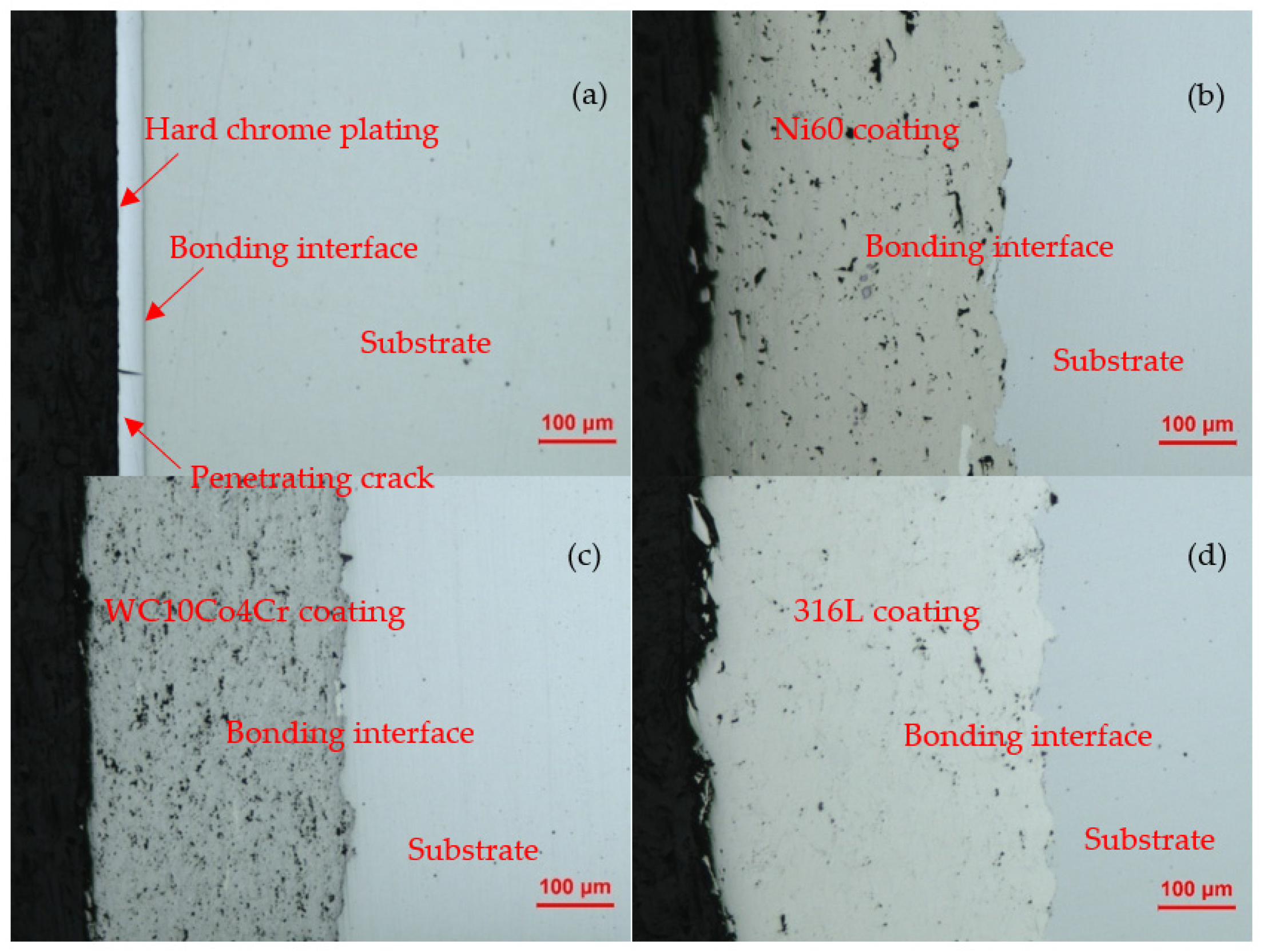
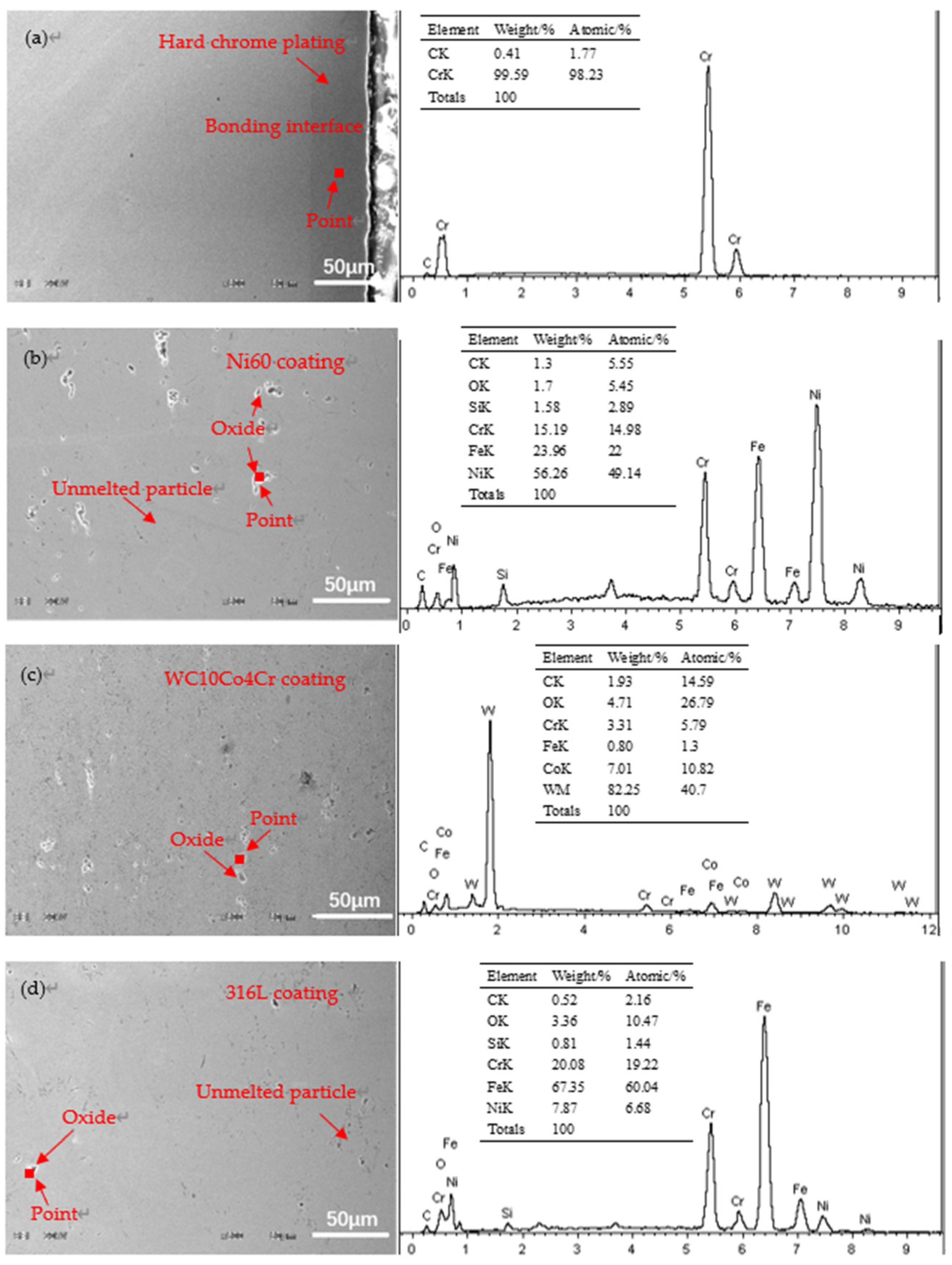
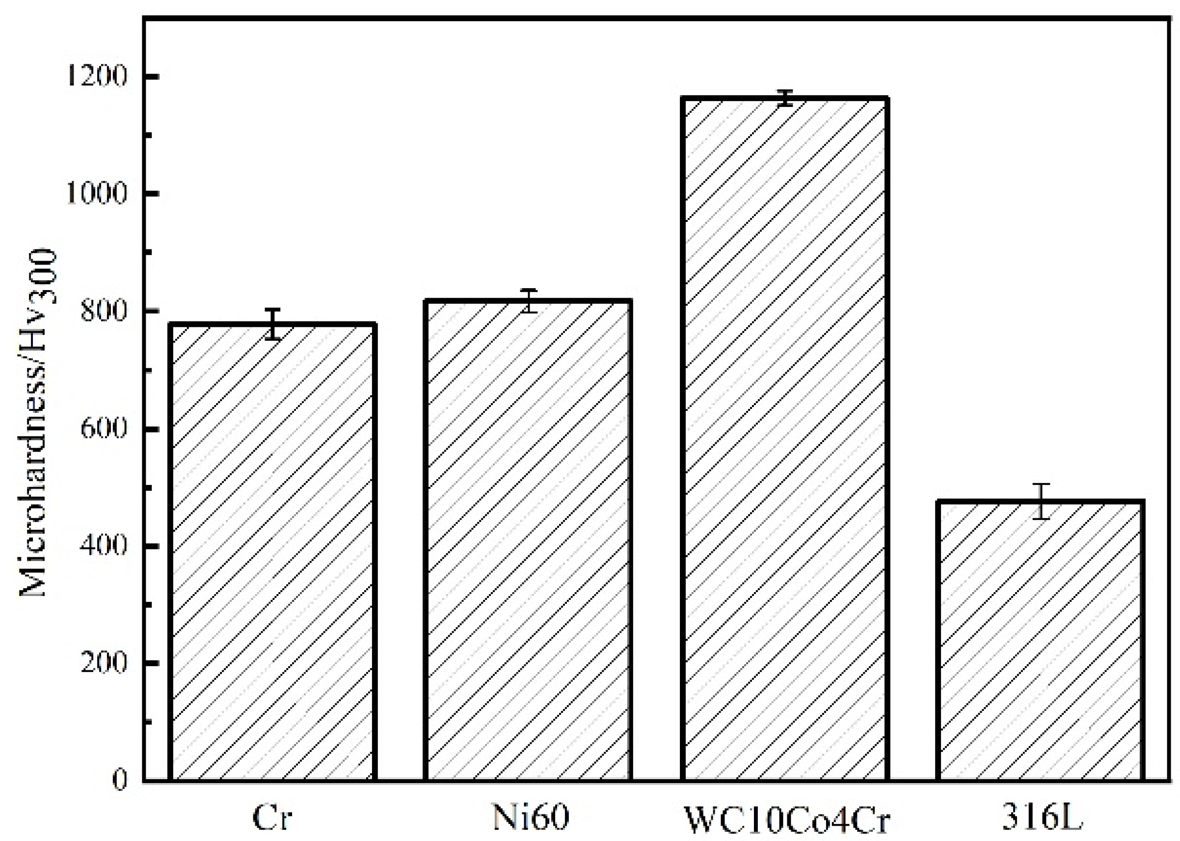
  • There is a microcrack in the plating. The thickness of the plating is 26–28 μm, and the microhardness is 778.6 ± 25.4 Hv300. The thickness of the HVOF coating is 420–450 μm, and the coating structure is uniformly compact without an obvious crack or pore in the internal part. The bonding interface between the coating and basal body is closely combined and embedded with each other, and the binding method is mechanical occlusion. The microhardness of HVOF coatings ranked from high to low is WC10Co4Cr coating, Ni60 coating, and 316L coating; the values are 1163.6 ± 12.4 Hv300, 817.5 ± 18.3 Hv300, and 476.4 ± 29.7 Hv300, respectively.
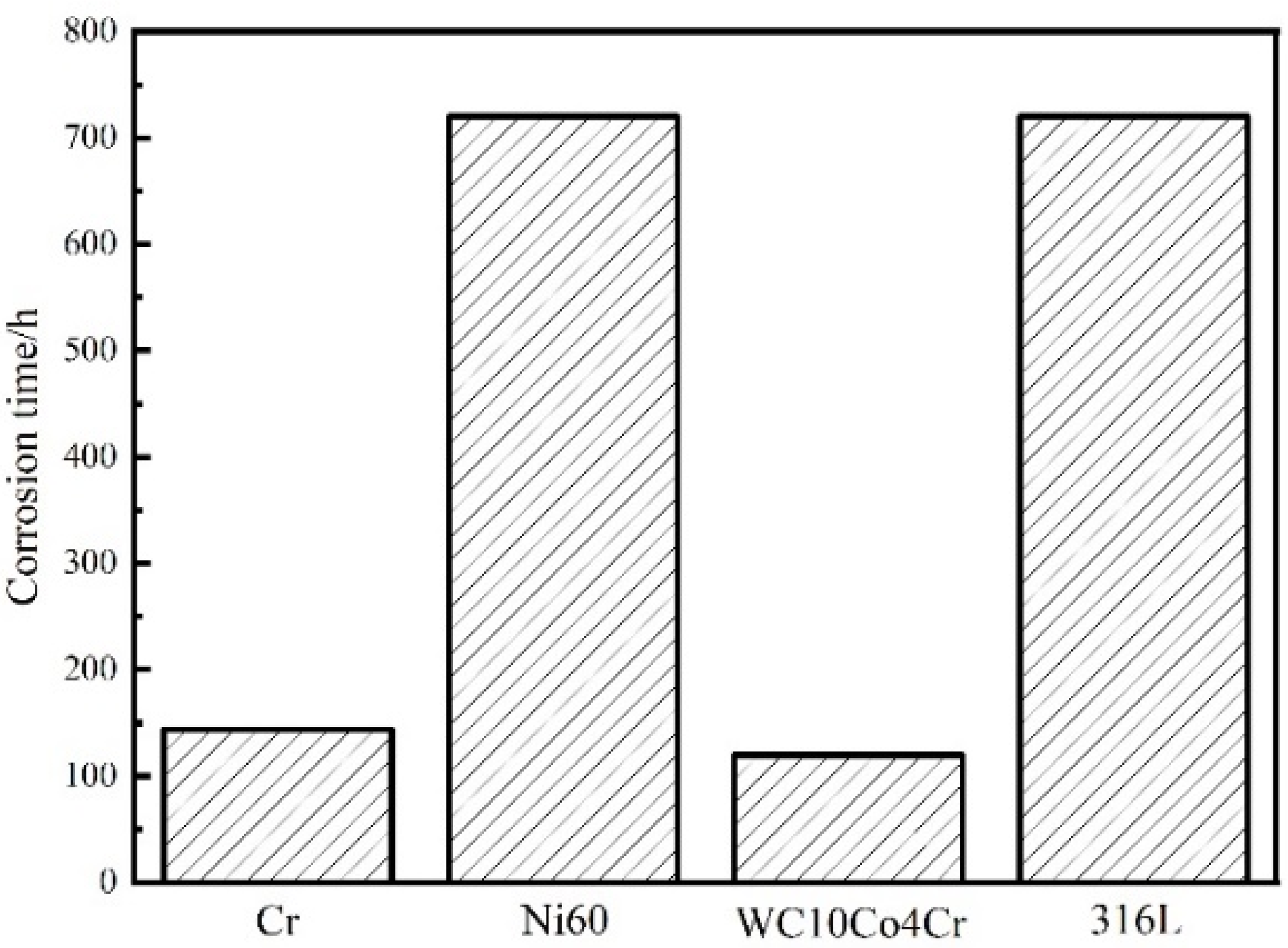
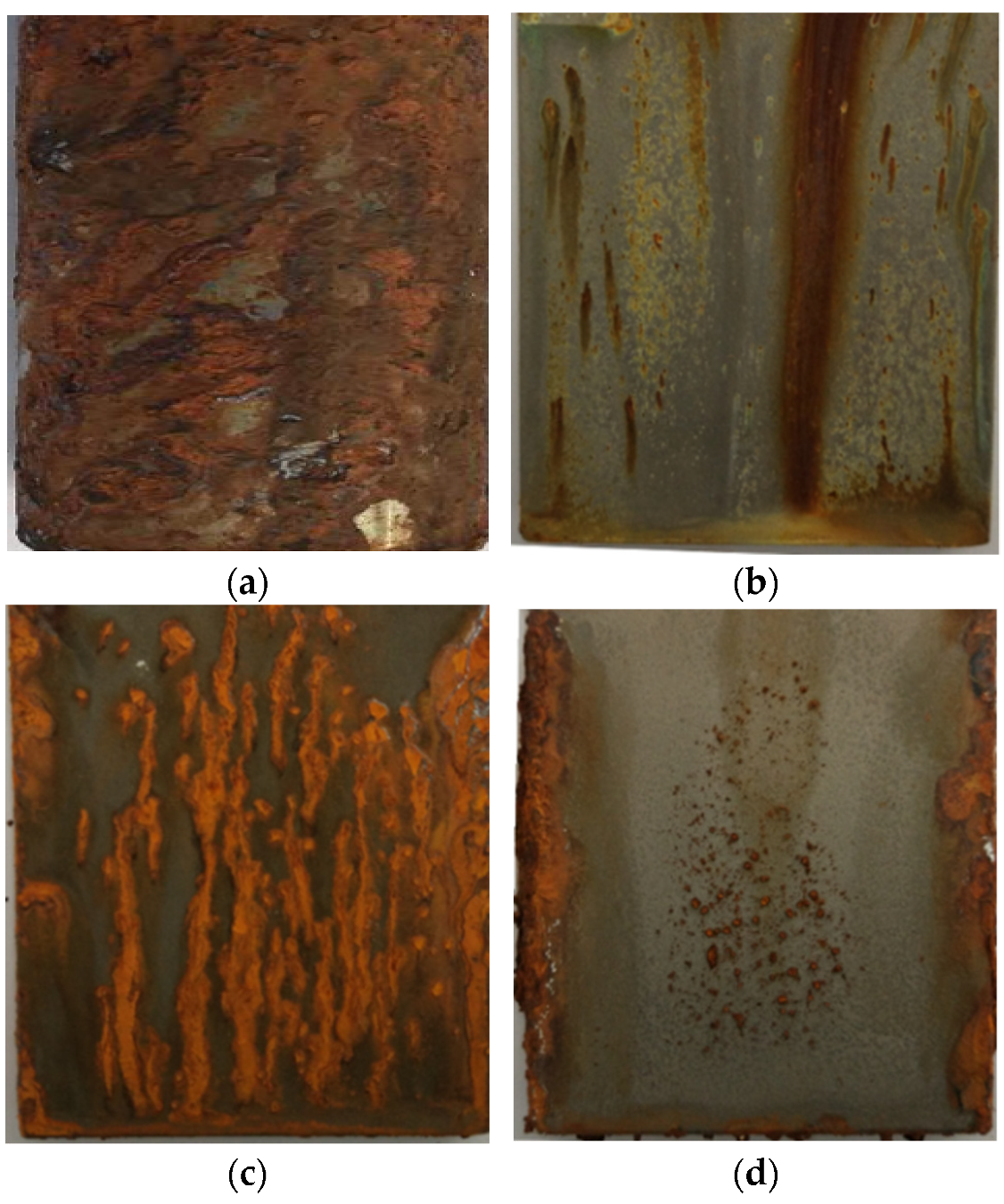
  • In the neutral salt spray test, the hard chrome plating would rust at 144 h, while the WC10Co4Cr coating would show rustiness at 120 h. The Ni60 coating and 316L coating have better corrosion resistance since they exhibit rustiness at 720 h during the test. The corrosion resistance of Ni60 coating and 316L coating is nearly five times that of hard chrome plating.
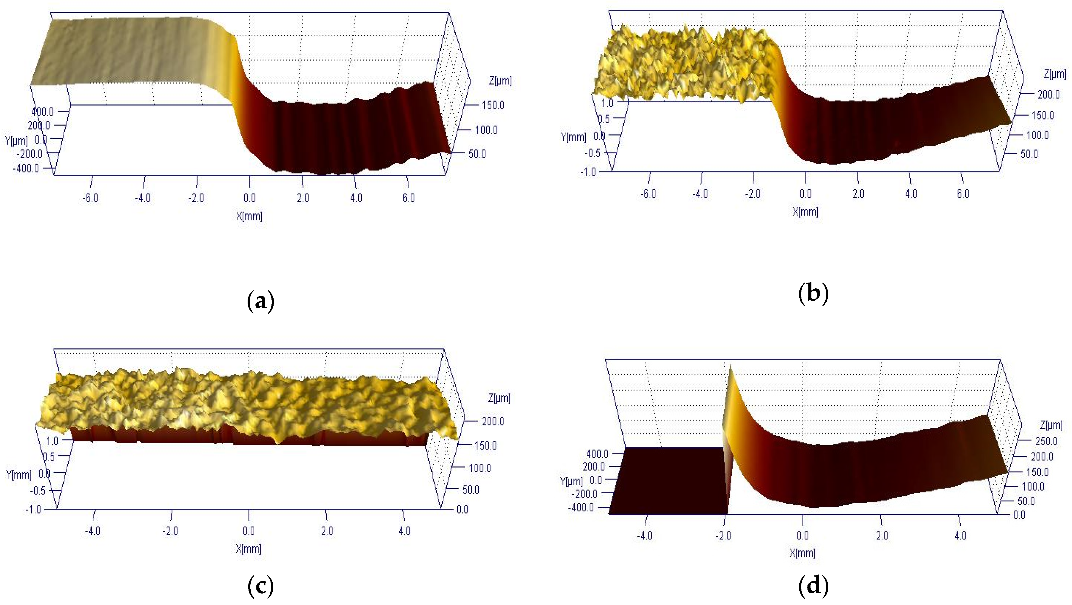
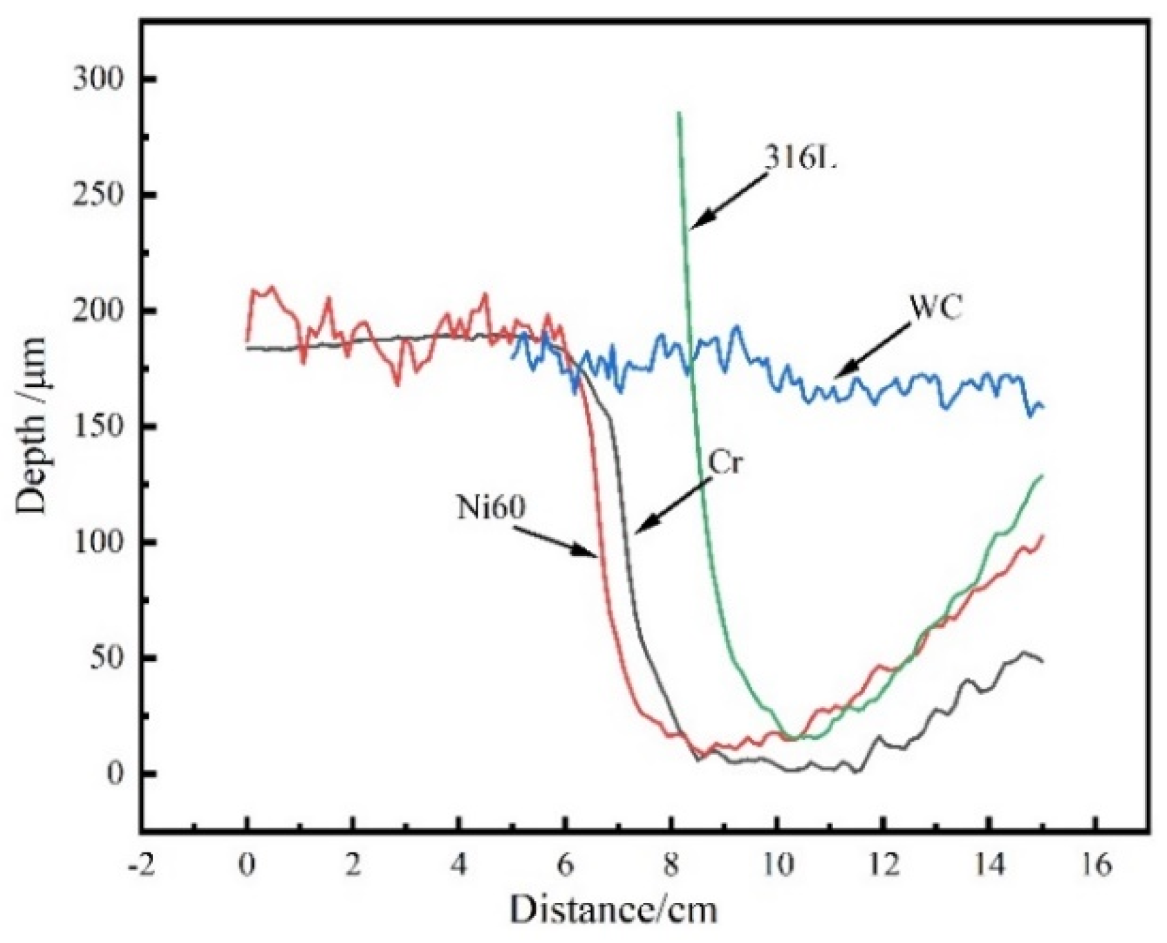
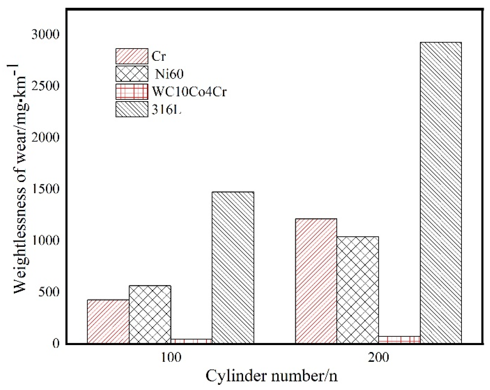
  • The hard chrome plating has a better wear resistance performance, comparable to that of the Ni60 coating. The wear resistance of the 316L coating is much weaker, while the wear resistance of WC10Co4Cr coating is more than four times that of hard chrome plating.
  • Under the harsh corrosive wear environment, the refabricating HVOF Ni60 coating is a more suitable replacement for the hydraulic support column coating than the hard chrome plating.

Author Contributions

M.W.: conceptualization, investigation, data curation, and writing—original draft. L.P.: supervision. L.P., C.W., T.Y., M.G., H.D. and S.Y.: review and editing. All authors have read and agreed to the published version of the manuscript.

Funding

This research received no external funding.

Institutional Review Board Statement

Not applicable.

Informed Consent Statement

Not applicable.

Data Availability Statement

Data sharing is not applicable to this article.

Conflicts of Interest

The authors declare no conflict of interest.

References

  1. Liang, M.; Fang, X.; Li, S.; Wu, G.; Ma, M.; Zhang, Y. A fiber Bragg grating tilt sensor for posture monitoring of hydraulic supports in coal mine working face. Meas. J. Int. Meas. Confed. 2019, 138, 305–313. [Google Scholar] [CrossRef]
  2. Nie, W.; Cheng, W.; Zhang, L.; Zhao, S.; Wang, H.; Zhu, L. Optimization research of hydraulic support in fully mechanized caving face. Procedia Eng. 2014, 84, 770–778. [Google Scholar] [CrossRef] [Green Version]
  3. Yang, X.; Wang, R.; Wang, H.; Yang, Y. A novel method for measuring pose of hydraulic supports relative to inspection robot using LiDAR. Meas. J. Int. Meas. Confed. 2020, 154, 107452. [Google Scholar] [CrossRef]
  4. Shao, Q.; Li, S.; Liu, L.; Zhou, J.; Xu, H. The influence on the corrosion of hydraulic support system of chloride ions in the transmission medium and preventive measures. Procedia Eng. 2011, 26, 1214–1219. [Google Scholar] [CrossRef] [Green Version]
  5. Wang, F.; Duan, C.; Tu, S.; Liang, N.; Bai, Q. Hydraulic support crushed mechanism for the shallow seam mining face under the roadway pillars of room mining goaf. Int. J. Min. Sci. Technol. 2017, 27, 853–860. [Google Scholar] [CrossRef]
  6. Matikainen, V.; Rubio Peregrina, S.; Ojala, N.; Koivuluoto, H.; Schubert, J.; Houdková, Š.; Vuoristo, P. Erosion wear performance of WC-10Co4Cr and Cr3C2-25NiCr coatings sprayed with high-velocity thermal spray processes. Surf. Coat. Technol. 2019, 370, 196–212. [Google Scholar] [CrossRef]
  7. Liu, W.H.; Shieu, F.S.; Hsiao, W.T. Enhancement of wear and corrosion resistance of iron-based hard coatings deposited by high-velocity oxygen fuel (HVOF) thermal spraying. Surf. Coat. Technol. 2014, 249, 24–41. [Google Scholar] [CrossRef]
  8. Keshavamurthy, R.; Sudhan, J.M.; Kumar, A.; Ranjan, V.; Singh, P.; Singh, A. wear behaviour of hard chrome and tungsten carbide-hvof coatings. Mater. Today Proc. 2018, 5, 24587–24594. [Google Scholar] [CrossRef]
  9. Picas, J.A.; Forn, A.; Matthäus, G. HVOF coatings as an alternative to hard chrome for pistons and valves. Wear 2006, 261, 477–484. [Google Scholar] [CrossRef]
  10. Bolelli, G.; Giovanardi, R.; Lusvarghi, L.; Manfredini, T. Corrosion resistance of HVOF-sprayed coatings for hard chrome replacement. Corros. Sci. 2006, 48, 3375–3397. [Google Scholar] [CrossRef]
  11. Yang, W.-j.; Zou, L.; Cao, X.-y.; Liu, J.-h.; Li, D.-j.; Cai, Z.-b. Fretting wear properties of HVOF-sprayed CoMoCrSi coatings with different spraying parameters. Surf. Coat. Technol. 2019, 358, 994–1005. [Google Scholar] [CrossRef]
  12. Najib, A.Z.P.; Kamdi, Z.; Patar, M.A.A.; Hatta, M.N.M.; Yunos, M.Z.; Ainuddin, A.R. Corrosion behaviour of WC-Ni high velocity oxy-fuel (HVOF) coating with the influence of spraying parameter. Mater. Today Proc. 2019, 29, 100–103. [Google Scholar] [CrossRef]
  13. Zavareh, M.A.; Doustmohammadi, E.; Sarhan, A.A.D.M.; Karimzadeh, R.; Moozarm Nia, P.; Al/Kulpid Singh, R.S. Comparative study on the corrosion and wear behavior of plasma-sprayed vs. high velocity oxygen fuel-sprayed Al8Si20BN ceramic coatings. Ceram. Int. 2018, 44, 12180–12193. [Google Scholar] [CrossRef]
  14. Kaur, M.; Singh, H.; Prakash, S. A survey of the literature on the use of high velocity oxy-fuel spray technology for high temperature corrosion and erosion-corrosion resistant coatings. Anti-Corros. Methods Mater. 2008, 55, 86–96. [Google Scholar] [CrossRef]
  15. Hamatani, H.; Ichiyama, Y.; Kobayashi, J. Mechanical and thermal properties of HVOF sprayed Ni based alloys with carbide. Sci. Technol. Adv. Mater. 2002, 3, 319–326. [Google Scholar] [CrossRef]
  16. Fu, W.; Chen, Q.Y.; Yang, C.; Yi, D.L.; Yao, H.L.; Wang, H.T.; Ji, G.C.; Wang, F. Microstructure and properties of high velocity oxygen fuel sprayed (WC-Co)-Ni coatings. Ceram. Int. 2020, 46, 14940–14948. [Google Scholar] [CrossRef]
  17. Smith, R.W.; Knight, R. Thermal spraying I: Powder consolidation-From coating to forming. Jom 1995, 47, 32–39. [Google Scholar] [CrossRef]
  18. Yao, H.L.; Yang, C.; Yi, D.L.; Zhang, M.X.; Wang, H.T.; Chen, Q.Y.; Bai, X.B.; Ji, G.C. Microstructure and mechanical property of high velocity oxy-fuel sprayed WC-Cr3C2-Ni coatings. Surf. Coat. Technol. 2020, 397, 126010. [Google Scholar] [CrossRef]
  19. Kulkarni, A.; Gutleber, J.; Sampath, S.; Goland, A.; Lindquist, W.B.; Herman, H.; Allen, A.J.; Dowd, B. Studies of the microstructure and properties of dense ceramic coatings produced by high-velocity oxygen-fuel combustion spraying. Mater. Sci. Eng. A 2004, 369, 124–137. [Google Scholar] [CrossRef]
  20. Sidhu, T.S.; Prakash, S.; Agrawal, R.D. Studies on the properties of high-velocity oxy-fuel thermal spray coatings for higher temperature applications. Mater. Sci. 2005, 41, 805–823. [Google Scholar] [CrossRef]
  21. Hong, S.; Lin, J.; Wu, Y.; Wu, J.; Zheng, Y.; Zhang, Y.; Cheng, J.; Sun, W. Cavitation erosion characteristics at various flow velocities in NaCl medium of carbide-based cermet coatings prepared by HVOF spraying. Ceram. Int. 2021, 47, 1929–1939. [Google Scholar] [CrossRef]
  22. Hong, S.; Wu, Y.; Zhang, J.; Zheng, Y.; Qin, Y.; Lin, J. Ultrasonic cavitation erosion of high-velocity oxygen-fuel (HVOF) sprayed near-nanostructured WC-10Co-4Cr coating in NaCl solution. Ultrason. Sonochem. 2015, 26, 87–92. [Google Scholar] [CrossRef]
  23. Feitosa, F.R.P.; Gomes, R.M.; Silva, M.M.R.; De Lima, S.J.G.; Dubois, J.M. Effect of oxygen/fuel ratio on the microstructure and properties of HVOF-sprayed Al59Cu25.5Fe12.5B3 quasicrystalline coatings. Surf. Coat. Technol. 2018, 353, 171–178. [Google Scholar] [CrossRef]
  24. Qiao, L.; Wu, Y.; Hong, S.; Cheng, J.; Wei, Z. Influence of the high-velocity oxygen-fuel spray parameters on the porosity and corrosion resistance of iron-based amorphous coatings. Surf. Coat. Technol. 2019, 366, 296–302. [Google Scholar] [CrossRef]
  25. Baik, J.S.; Kim, Y.J. Effect of nozzle shape on the performance of high velocity oxygen-fuel thermal spray system. Surf. Coat. Technol. 2008, 202, 5457–5462. [Google Scholar] [CrossRef]
  26. Elshalakany, A.B.; Osman, T.A.; Hoziefa, W.; Escuder, A.V.; Amigó, V. Comparative study between high-velocity oxygen fuel and flame spraying using MCrAlY coats on a 304 stainless steel substrate. J. Mater. Res. Technol. 2019, 8, 4253–4263. [Google Scholar] [CrossRef]
  27. Kanno, A.; Takagi, K.; Arai, M. Influence of chemical composition, grain size, and spray condition on cavitation erosion resistance of high-velocity oxygen fuel thermal-sprayed WC cermet coatings. Surf. Coat. Technol. 2020, 394, 125881. [Google Scholar] [CrossRef]
  28. Metallic Materials-Vickers Hardness Test-Part 1: Test Method ISO 6507.1-1997.
  29. Corrosion tests in artificial atmospheres-Salt spray tests ISO9227-2006.
  30. Standard Test Method for Measuring Abrasion Using the Dry Sand/Rubber Wheel Apparatus ASTMG65-2004(2010).
  31. Pan, J.; Hu, S.; Niu, A.; Ding, K.; Yang, L. Numerical analysis of particle impacting and bonding processes during high velocity oxygen fuel spraying process. Appl. Surf. Sci. 2016, 366, 187–192. [Google Scholar] [CrossRef]
  32. Metallic and other inorganic coatings-Definitions and conventions concerning the measurement of thickness ISO 2064-1996.
  33. Standard Test Methods for Determining Area Percentage porosity in Thermal Sprayed Coatings ASTME2109.1-2014.
  34. Koutský, J. High velocity oxy-fuel spraying. J. Mater. Process. Technol. 2004, 157–158, 557–560. [Google Scholar] [CrossRef]
Figure 1. Schematic diagram of HVOF spraying.
Coatings 11 01457 g001
Figure 2. Self-made wear tester of abrasive particles.
Coatings 11 01457 g002
Figure 3. Schematic diagram of particle deposition.
Coatings 11 01457 g003
Figure 4. Metallographic of hard chrome plating and HVOF coatings. (a) hard chrome plating cross-section (b) Ni60 coating cross-section (c) WC10Co4Cr coating section (d) 316L coating cross-section.
Coatings 11 01457 g004
Figure 5. Microstructure and EDS of hard chrome plating and HVOF coatings. (a) hard chrome plating, (b) Ni60 coating, (c) WC10Co4Cr coating, (d) 316L coating.
Coatings 11 01457 g005
Figure 6. Microhardness of hard chrome plating and HVOF coatings.
Coatings 11 01457 g006
Figure 7. Neutral salt spray test of hard chrome plating and HVOF coatings.
Coatings 11 01457 g007
Figure 8. Corrosion morphology of HVOF coatings and hard chrome plating by salt spray test. (a) hard chrome plating, (b) Ni60 coating, (c) WC10Co4Cr coating, (d) 316L coating.
Coatings 11 01457 g008
Figure 9. 3D CM images and cross-sectional profiles of hard chrome plating and HVOF coatings. (a) hard chrome plating, (b) Ni60 coating, (c) WC10Co4Cr coating, (d) 316L coating.
Coatings 11 01457 g009aCoatings 11 01457 g009b
Figure 10. The wear rate of hard chrome plating and HVOF coatings.
Coatings 11 01457 g010
Table 1. Powder parameters.
Powder NameElementPowder Specification
FeCrCoWNi
Ni6018.9615.1958.86−53 + 25 μm
WC10Co4Cr3.819.8882.25−45 + 15 μm
316L64.9920.5310.06−53 + 25 μm
Table 2. HVOF Spraying process parameters.
ParameterValue
Kerosene flow rate/(L·h−1)32
Oxygen flow rate/(L·min−1)800
Spray distance/mm350
Nozzle length/mm150
Feeding speed/(g·min−1)70
Spray gun moving speed/(mm·s−1)500
Scan the steps/mm5
Publisher’s Note: MDPI stays neutral with regard to jurisdictional claims in published maps and institutional affiliations.

