Investigation of Weld Zone and Fracture Surface of Friction Stir Lap Welded 5052 Aluminum Alloy and 304 Stainless Steel Joints


Department of Mechanical Engineering, Universiti Teknologi PETRONAS, Perak 32610, Malaysia
*
Author to whom correspondence should be addressed.
Coatings 2020, 10(11), 1062; https://doi.org/10.3390/coatings10111062
Submission received: 8 October 2020
/
Revised: 23 October 2020
/
Accepted: 30 October 2020
/
Published: 4 November 2020
(This article belongs to the Special Issue Development of Friction Stir Welding and Processing)
Abstract
:Dissimilar material joining of aluminum and steel in the present scenario is an important criterion in the manufacturing industry, especially because of their low weight and technical performance. In the present investigation, AA5052 and SS304 are friction stir welded in lap configuration with different tilt angles, welding speed, pin depth, and tool rotational speed, with aluminum as the top plate. A maximum of 3.16 kN shear strength was achieved at 2.5° tilt angle when the penetration depth was 4.3 mm. The shear strength samples were studied for fracture analysis and it was found that fracture of the samples mainly occurred on the aluminum side and the fracture demonstrated both brittle and ductile failure, consisting of quasi-cleavage, trans-granular, and intergranular fracture areas. Field emission scanning electron microscope images at the interfacial region of the weld show that different intermetallic compounds were formed at various zones of the joint with respect to the change in process parameters. It was observed from energy dispersive spectroscopy that Al-rich intermetallic compounds were formed at the interfacial region of the welded samples. Amongst the process parameters, change in the tilt angle affected the weld zone significantly. The thickness of the intermetallic compound (IMC) layer formed with 800 and 1000 rpm at 2.5° tilt angle was between 2.5 and 3 μm, which resulted in achieving better joint strength. AlFe, AlFe3, Al13Fe4, and Al5Fe2 were the different intermetallic compounds detected using X-ray diffraction with different process parameters. The hardness of the samples ranged between (300 and 630) HV, which further supports the formation of AlFe and AlFe3 intermetallic compounds.
1. Introduction
Manufacturing industries are looking for cost-effective lightweight material production to increase the efficiency of vehicles in different sectors. Dissimilar material welding is one of the methods utilized to produce the needed materials. Friction stir welding (FSW) is one of the technologies that is used to join two different materials from among the likes of aluminum, magnesium, steel, and copper. Different process parameters and their variations have been used to produce defect-free welds to answer the need for dissimilar metal welding in the manufacturing industry. Aluminum and steel welding has opened new doors in the automobile and aerospace industry in reducing the overall weight of the components, which will improve efficiency [1,2,3].
Conventional welding techniques such as laser beam welding and tungsten inert gas welding were also used to join aluminum and steel joints [4,5] but friction stir welding is more advantageous because of its capability of welding the materials with lower heat. In the present scenario [6,7], friction stir lap welding (FSLW) is a better technique to weld aluminum and steel alloys. This process is usually performed with aluminum as the top plate to overcome the defects that are commonly observed in dissimilar welding. Intermetallic compounds formed during the dissimilar welding are significant as they decide the quality of the weld formed. Springer et al. [8] confirmed that Al2Fe5 is formed at 600–675 °C during the interdiffusion between aluminum and low carbon steel and a thicker layer of intermetallic compound (IMC) is obtained at 600 °C. In a butt joint configuration between aluminum 5005 and St-52 steel, various IMCs like FeAl, Fe2Al5, and FeAl3 are formed and the growth of the IMCs is predicted by finite element analysis, which gave the insight that IMC thickness is the deciding factor to obtain acceptable tensile strength [9,10,11]. Anaman et al. [12] performed butt welds between 5052 aluminum and Dual-Phase steel, which resulted in a three-layer weld zone, where the middle layer was a mixed one, with complex intermetallic compounds like AlFe, Al3Fe2, and AlFe2 which are responsible for increasing the hardness in all three layers compared to the base metal. Liu et al. [13] friction welded aluminum and steel alloys where the weld resulted in the formation of a thick layer of IMC. The thickness of the IMCs was not uniform and was dependent on the contact surface of AA6061 aluminum and SS304 steel rods. The IMCs were found to be thinnest at the center region and thicker at the half radius (R/2) of the joint. According to some researchers [14,15,16,17], the tool tilt angle is responsible for the thickness of the IMCs; with the increasing tilt angle, the thickness of the IMCs is increased, which in turn reduces the joint strength. FeAl3 and FeAl2 are the common IMCs found, with tilt angles of 1° and 3°. Pourali et al. [18] found that the IMCs are not responsible for the reduction in shear tensile strength. The microcracks and voids formed during the welding of aluminum 1100 and St-37 were the main reasons for not obtaining a good quality weld. Tsutomu et al. [19] found that IMCs formed between 1050 aluminum and mild steel are problematic because they reduce the strength of the joint and reported that temperature is an important criterion behind the formation of IMCs with respect to contact of the tool with the plates. When 304 stainless steel is welded to commercially pure aluminum, Al3Fe is detected at the interface of the joint, and the tensile strength is found to be 78% of the base aluminum. The aluminum side is severely deformed, whereas the deformation on the steel side is minimal. Apart from the weld nugget, other IMCs like Fe2Al5, Al13Fe4 are also detected near the weld interface [20,21]. A correlation between the IMCs and shear strength was developed by Picot et al. [22], which states that a good tensile strength of 130 MPa is achieved when the IMC thickness is 15 μm. However, with the increasing IMC thickness, the tensile strength is reduced to 80 MPa. Dehghani et al. [23] found that FeAl6 and Fe2Al5 are formed when the welding speeds are low, resulting in thicker IMCs, which in return reduces the tensile strength of the joint. The thickness of the IMCs is reduced by increasing the welding speed, which results in better tensile strength.
From different studies [24,25,26,27,28,29], it is evident that AlFe, Al3Fe, Fe2Al5, Fe3Al, FeAl2 are the common IMCs formed at the weld interface. Generally, the thickness of IMCs has a major impact on tensile strength. Mostly, higher thickness IMCs have shown poor tensile strength when compared to thin IMCs. The ideal range of thickness of the IMCs to achieve better tensile strength is not perfectly defined. Some studies [30,31,32,33] have shown that the brittleness of the IMCs is the major property that affects joint strength. Aluminum-rich intermetallic compounds are more brittle when compared to Fe-rich intermetallic compounds. Fe-rich IMCs have shown better tensile strength results. Interestingly, Mahto et al. [34] found that underwater friction stir welding of AA6061-T6 and AISI 304 yielded better results and thinner IMCs when compared normal friction stir welding.
According to the above discussion, IMCs formed at the interface and their thickness are responsible for influencing the weld strength. In the present work, the authors investigated the mechanical properties of the weld zone and the IMCs formed at the interfacial region of AA5052 and SS304 joints.
2. Materials and Methods
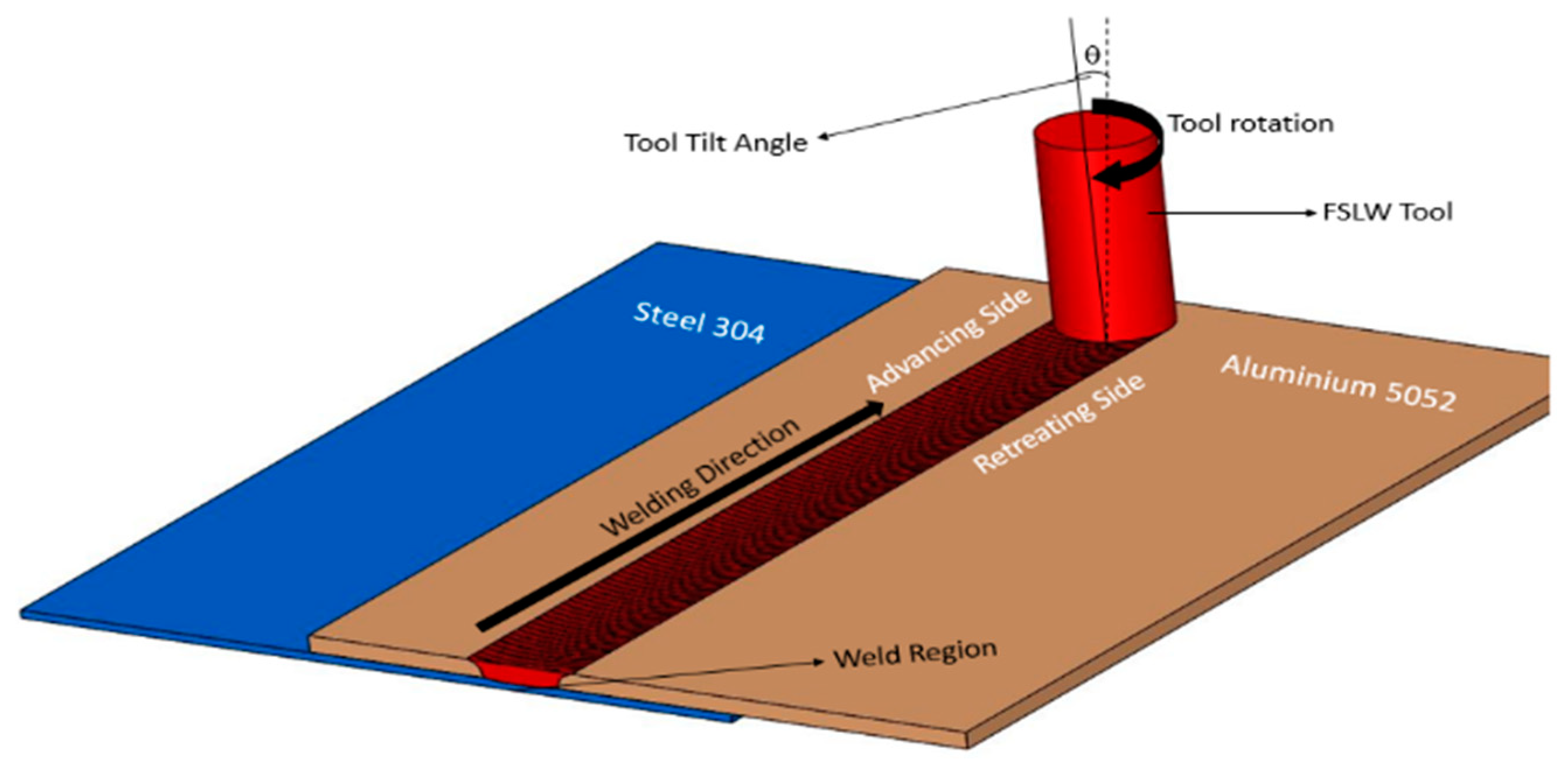
AA5052 plates were welded to SS304 plates in lap configuration, with aluminum as the top plate, as shown in Figure 1. The size of the AA5052 and SS304 plates was 100 mm × 150 mm and the thickness of AA5052 was 4 mm, while that of SS304 was 2 mm. The procedure, process parameters, tool, and the experimental setup were according to the Taguchi’s optimization of the design of experiments [35]. According to Taguchi’s experimental design, the total degrees of freedom (DOF) for each factor with a set of three levels is 2. In the present study, we had four factors with three levels each, so the total DOF was 8. The orthogonal array satisfying the 8 DOF with three levels was L9. The process parameters and their levels for friction stir lap welding of aluminum 5052 and stainless steel 304 are given in Table 1 and the L9 orthogonal array is shown in Table 2. The welded joints were cut in 10 mm × 20 mm dimensions using an electrical discharge machine (EDM, Mitsubishi, Tokyo, Japan wire-cut for the microstructural analysis. Samples were mounted, polished, and then etched with Nital on the steel side and Kellar’s reagent on the aluminum side. Etched samples were later analyzed by field emission scanning electron microscopy (FESEM, Zeiss Supra55 VP, Eindhoven, The Netherlands). X-ray diffraction analysis (X’Pert³, Malvern Panalytical, Malvern, UK) was conducted with Cu-Kα source radiation with a scan range of 0° to 80° to find the different phases of IMCs formed in the weld zone. The shear strength of the weld samples was measured according to ASTM-E8 standards. Fractography analysis of the broken samples at the interfacial region of aluminum and steel was conducted using FESEM. The hardness of the samples was determined using a Vickers hardness testing machine with a dwell time of 20 s and a load of 1000 gf.
3. Results and Discussion
It has been established that the tilt angle of the FSLW tool plays an important role in achieving better joint strength and eliminating the defects that occur during the lap welding of AA5052 and SS304 alloys [36]. In this study, the microstructural changes and the formation of intermetallic compounds at the interface of the weld were analyzed according to the change in tilt angle. The welded surfaces of the samples are shown in Figure 2. A tunnel defect, which is commonly seen in FSW, was formed because of insufficient heat during the welding process and could be observed on the surfaces of samples LW-5 and LW-9 when the experiments were conducted at 0° tilt angle. The defects in the sample LW-1 were not visible on the surface of the weld but were visible through the keyhole formed at the end of the welding process. However, there were no surface defects when the tilt angle of the tool was further increased to 1.5° and 2.5° and the formation of the onion rings was visible on the surface.
3.1. Microstructural Analysis of the Lap Joints
3.1.1. Microstructure of the Lap Joints Welded at 0° Tilt Angle
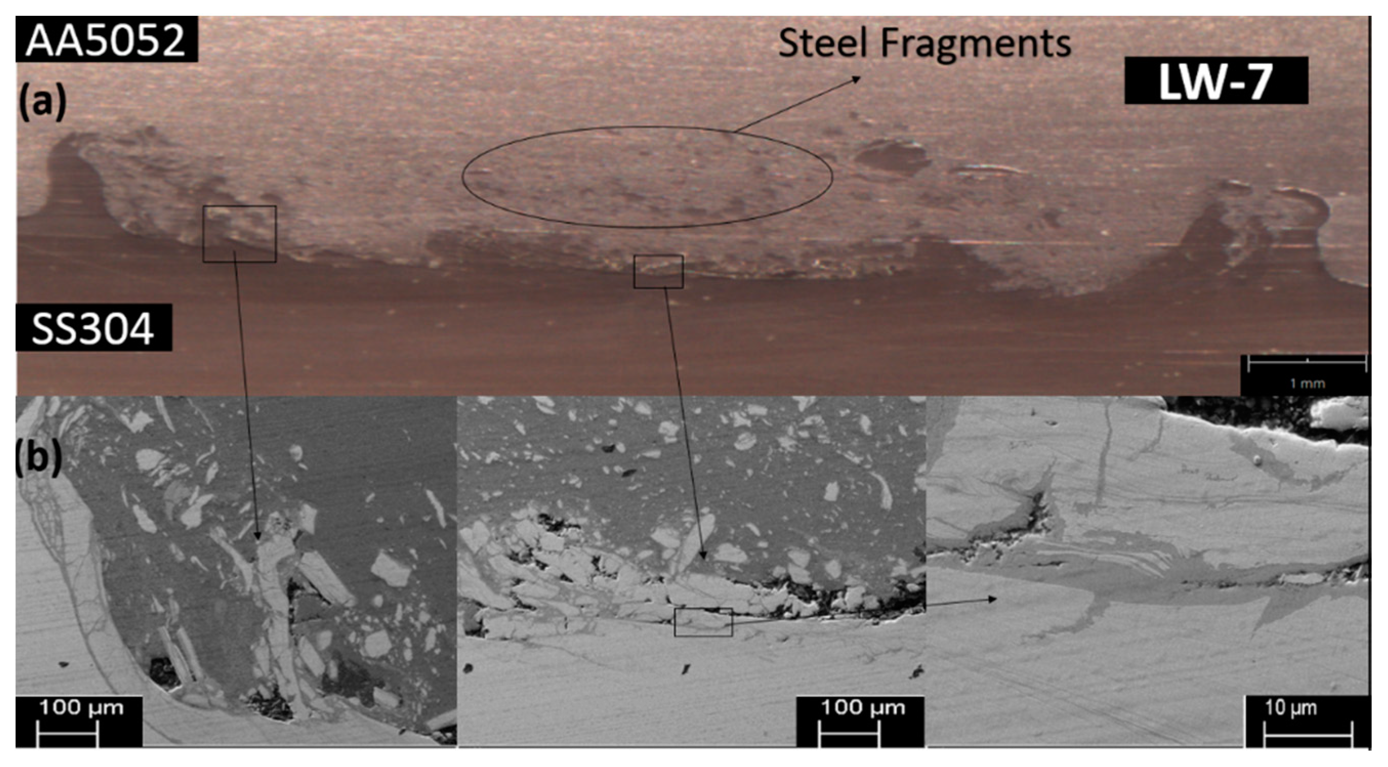
When the lap joint was performed with a 0° tilt angle with a welding speed of 20 mm/min, a penetration depth of 0.1 mm into the steel and tool rotational speed of 800 rpm, a huge tunnel defect was formed on the advancing side and a lot of cracks were detected at the interface of the two materials. Defects lead to improper mixing of the material, resulting in scattering of steel fragments into the aluminum side, as shown in Figure 3. The scattering of the steel particles was less on the advancing side because the rotating shoulder dragged the particles from the steel surface on the advancing side, which were later settled on the retreating side. The mixed stir zone of the weld clearly shows that the intermixing of the materials did not occur properly, which was the main reason behind the non-formation of the intermetallic layer between the two materials.
Energy dispersive spectroscopy (EDS) was performed at three different points in the mixed stir zone and the spectra are shown in Figure 4. The spectra show the presence of both Fe and Al elements in the interfacial region. Because of the improper mixing of the materials and diffusion between Al and Fe atoms, the IMCs are scattered instead of forming a layer at the mixed stir zone. The intermetallic compound cannot be predicted with the help of the EDS spectrum because of the spatial resolution and crystallographic information but the composition of Al and Fe can be determined. As the materials undergo severe plastic deformation during the process because of the mechanical and thermal reactions, the presence of intermetallic compounds is inevitable. Steel particles are scattered just above the interfacial region, as shown in Figure 4, because of the stirring action of the tool pin. The formation of tunnel defect is also responsible for the scattering of the particles because of the improper mechanical mixing in the stir zone. The weight percentage of aluminum at different points is less than 50%, which significantly shows that Fe-rich intermetallic compounds can be formed in the interfacial region.
3.1.2. Microstructure of the Lap Joints Welded at 1.5° Tilt Angle
The tunnel defect was eliminated when the materials were joined with a welding speed of 20 mm/min, penetration depth was increased to 0.3 mm, and a tool rotational speed of 1200 rpm at 1.5° tilt angle. It is evident from Figure 5 that a hook is formed on both sides of the stir zone, leaving some cracks at the interface of two materials. The scattering of steel particles is almost equal on the advancing side and retreating side, which shows that the intermixing of materials is better when compared to the joint formed with 0° tilt angle. By increasing the penetration depth, a mechanical link was obtained in the form of a hook. It is evident from the micro-structure that the stirred zone looks different from the aluminum and steel zone, which is considered as the mixed layer which leads to the formation of intermetallic compounds. Apart from the unevenly scattered steel particles, discontinuous thin wave shapes which were formed in the stirring zone can be considered as the intermetallic compounds formed according to Figner et al. [37] because of the interdiffusion produced during the weld.
The EDS spectra at three different points with the presence of both Al and Fe elements confirm that intermetallic compounds are formed at the interfacial region, as shown in Figure 6. The intermetallic compounds formed can be predicted with the help of the Al/Fe binary phase diagram of [38]. The weight percentage of aluminum in point 1 spectrum is 57.59%, which shows the presence of Fe2Al5 IMC, which is stable when the aluminum percentage is around (~55 wt.%). The other two spectra reveal that the weight percentage of aluminum varies from point to point, which reveals that the IMCs have different thicknesses and the IMC layer at the interfacial region is not stable. Elemental mapping was conducted in the interfacial region, and the distribution of aluminum and steel particles can be perfectly seen. A thin discontinuous layer was detected at the interface of the joint which proves that improper mixing of materials has happened irrespective of the micro-cracks and voids. According to the elemental mapping images of Al and Fe in Figure 6, the interfacial region mainly consists of aluminum, which leads to the formation of Al-rich intermetallic compounds.
3.1.3. Microstructure of the Lap Joints Welded at 2.5° Tilt Angle
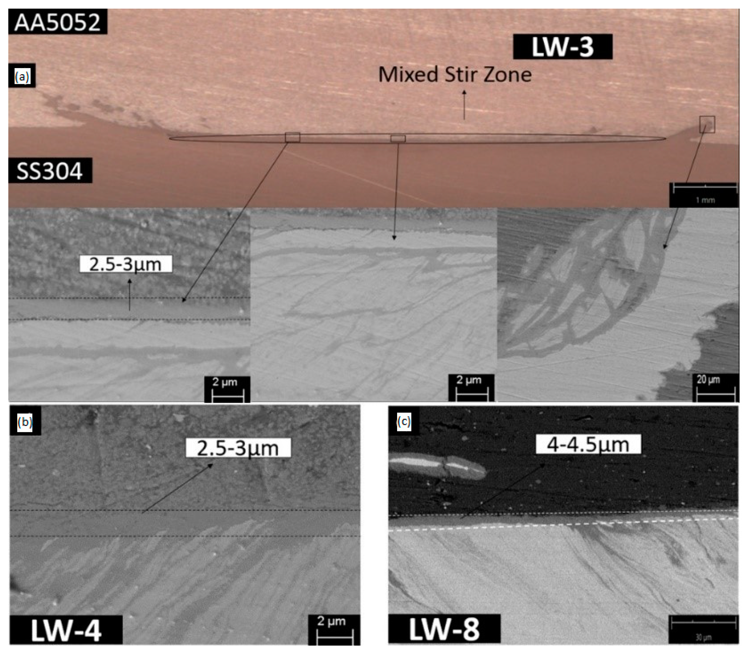
When the lap joint was performed with a 2.5° tilt angle with a welding speed of 40 mm/ min, a penetration depth of 0.3 mm into the steel, and tool rotational speed of 800 rpm, all the defects which were formed with 0° and 1.5° were eliminated, featuring a perfectly sound joint. The interface of the materials confirms that intermixing was sufficiently achieved, creating a streamline flow throughout the stirred zone, as shown in Figure 7a. The hooks were also formed on both sides of the mixed stirred zone, which improved the mechanical strength of the joint [36]. The scattering of steel particles was reduced, which could only be observed at the ends of the stirred zone region. The thin waves which formed because of the intermixing of the materials at the interface were the intermetallic layers formed between the two materials. Even the scattered steel particles on the advancing and retreating sides are surrounded by intermetallic layers. The thickness of the intermetallic layer measured with samples LW-3 and LW-4 was between 2.5 and 3 μm, as shown in Figure 7a,b. However, the thickness of the IMC layer increased to 4.5 μm with sample LW-8, as shown Figure 7c, because of the increase in the tool rotational speed, which leads to the increase in temperature, which results in a thicker IMC layer. IMC layer thickness of samples conducted at 2.5° tilt angle concludes that with tool rotational speeds of 800 and 1000 rpm, thinner IMCs can be achieved, which gives better joint strength when compared to the thicker IMCs formed with a tool rotational speed of 1200 rpm.
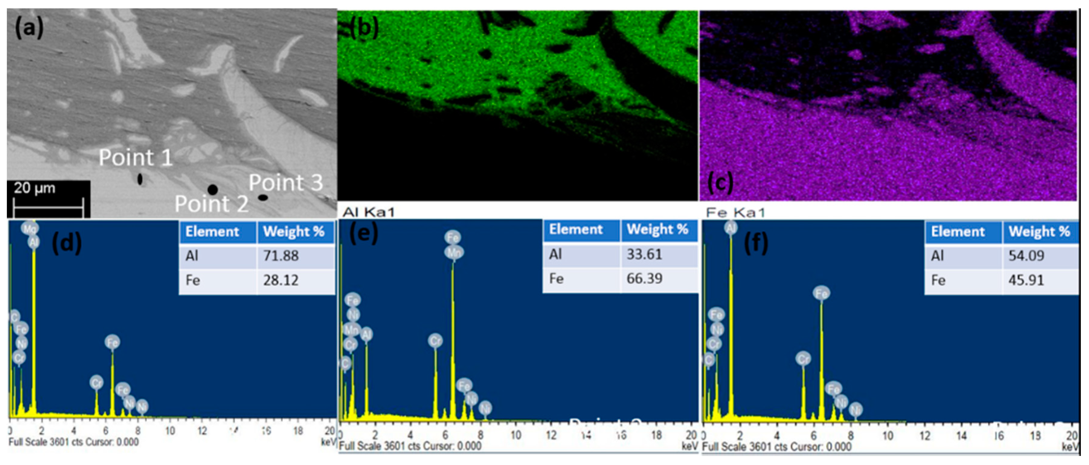
It is evident from the EDS spectra that Al and Fe elements were present in the interfacial region of the weld, which can be observed in Figure 8. According to Balamagendiravarman et al. [21], when the aluminum weight percentage is (~70 wt.%) at point 1, this is evidence of the formation of Al3Fe intermetallic compound. From the point 2 EDS spectrum, it is evident that Fe-rich intermetallic compounds are formed in the interfacial region When the aluminum weight percentage is (~55 wt.%), as shown in the point 3 spectrum, there is a significant change in the formation of Fe2Al5 IMC. The distribution of aluminum and steel particles is shown in Figure 8, which consists of elemental mapping at the interface of the joints. The hook formation, intermetallic layer, and scattered steel particles can be observed from mapping analysis.
3.2. XRD Analysis of Intermetallic Compounds Formed in FSLW Joints
Friction stir welding between two different materials is complex because of their mechanical and thermal properties; regardless of the change in process parameters, it is hard to control the formation of the IMCs because of the uneven heat distribution which results in the formation of intermetallic compounds. Tilt angle is the major contributing factor that decides the formation of defects in the weld zone. XRD patterns of three samples at different tilt angles are shown in Figure 9. AlFe is the common IMC formed irrespective of the change in tilt angle, which is mainly because of diffusion of aluminum and steel atoms. The formation of IMCs generally takes place between 500 and 1300 °C. Aluminum-rich intermetallic compounds are formed at lower temperatures, whereas Fe-rich intermetallic compounds are formed at elevated temperatures. Different intermetallic compounds, namely AlFe, AlFe3, Al13Fe4, and Al5Fe2, were detected in all the samples because of improper distribution of heat which was caused by the friction between the plates and the tool. AlFe and Al13Fe4 are the more stable compounds that can be confirmed from three different peaks in all the samples. The proper mixing of the material at different temperature ranges without defects results in the formation of the equilibrium AlFe compound. Al13Fe4 is formed when the melted Al reacts with undissolved Fe particles when the temperature crosses the melting point of aluminum [39]. AlFe3 is formed because of low rotational speed and improper mixing of the material, which are responsible for the low temperature during the welding. When the tool pin depth, rotational speed, and welding speed have increased, the temperature at the weld zone rises. When the temperature reaches the melting point of aluminum, the Fe diffuses into Al and results in the formation of Al5Fe2. According to Movahedi et al. [40], Al3Fe is unstable with the rise in temperature; as a result, Al5Fe2 is formed with the diffusion of Fe into aluminum. When the angle was increased to 2.5°, the contact between the pin and plates was better and gives us a defect-free weld and AlFe3 and Al5Fe2 were formed at the interfacial region. From the XRD results and Al/Fe binary phase diagram, it is evident that different intermetallic compounds are formed based on the diffusion of Fe and Al at different temperatures.
3.3. Mechanical Properties of the FSLW Joints
The samples for the shear strength test were cut according to ASTM-E8 standards. The mechanical properties of the base materials are shown in Table 3. Three samples were tested from each weld and the average of them was calculated, and the load vs. displacement graph is plotted in Figure 10. A maximum of 3.16 kN shear strength was recorded at 2.5° tilt angle with a penetration depth of 4.3 mm, a welding speed of 40 mm/min, and a tool rotational speed of 800 rpm, while the lowest shear strength was obtained at 0° tilt angle with a penetration depth of 4.2 mm, welding speed of 40 mm/min and, a tool rotational speed of 1200 rpm. Even though defect-free welds are obtained with 4.1 and 4.2 mm penetration depths, the shear strength of the welds was 2.28 and 2.48 kN because of the thicker IMCs formed at the interfacial region. It is noticeable from the shear strength values that tilt angle and penetration depth play an important role in determining the weld strength. Intermetallic compounds influence the ductility of the joint. The presence of thicker intermetallic compounds results in a brittle joint.
Intermetallic compounds present at the interfacial region can be recognized with the help of the hardness test. The hardness of the intermetallic compounds formed between Al and Fe approximately ranges from 350 to 1200 HV [41]. The hardness test was conducted at the cross-section of the lap joints from top to bottom. Hardness on the AA5052 kept increasing with the increase in penetration depth. The maximum hardness values for all the samples are in the welded region. The maximum hardness of 624 HV was achieved with the LW-3 sample, which was approximately an increase of 250% when compared to the SS304 base metal. The lowest hardness was obtained with the LW-9 sample, which has a huge tunnel defect. Hardness values are comparatively low for the samples that are welded at 0° tilt angle, because of the improper mixing of the aluminum and steel that leads to the formation of tunnel defect, whereas the hardness of the samples increased with the increase in tilt angle. The hardness values of the samples welded at 2.5° tilt angle are higher than those of the samples welded at 1.5°. Regardless of the defects, the hardness range for all the samples at the weld zone was between 300 and 630 HV, as shown in Figure 11. The higher hardness at the weld zone reflects the formation of IMCs in the interfacial region. According to Basariya et al. [30], AlFe has a hardness range of (491–667) HV and AlFe3 has a hardness range of (344–368) HV, which proves the presence of two intermetallic phases.
3.4. Fractography Analysis of the Lap Joints
3.4.1. Fracture Surface of the Lap Joints Welded at 0° Tilt Angle
FESEM was used to study the type of fracture that happened at the interface of aluminum and steel. The fracture surface of aluminum and steel shows that onion rings are formed in the stirred zone because of the tool pin. The onion rings were visible on the steel side because of the penetration depth of the tool pin. The cracks on either side of the weld zone can be observed in all the samples. The fracture surface on the advancing side and retreating side show that grooves are formed on both sides because of the penetration depth of a tool pin which caused the mechanical mixing of the material, which lead to the formation of hooks.
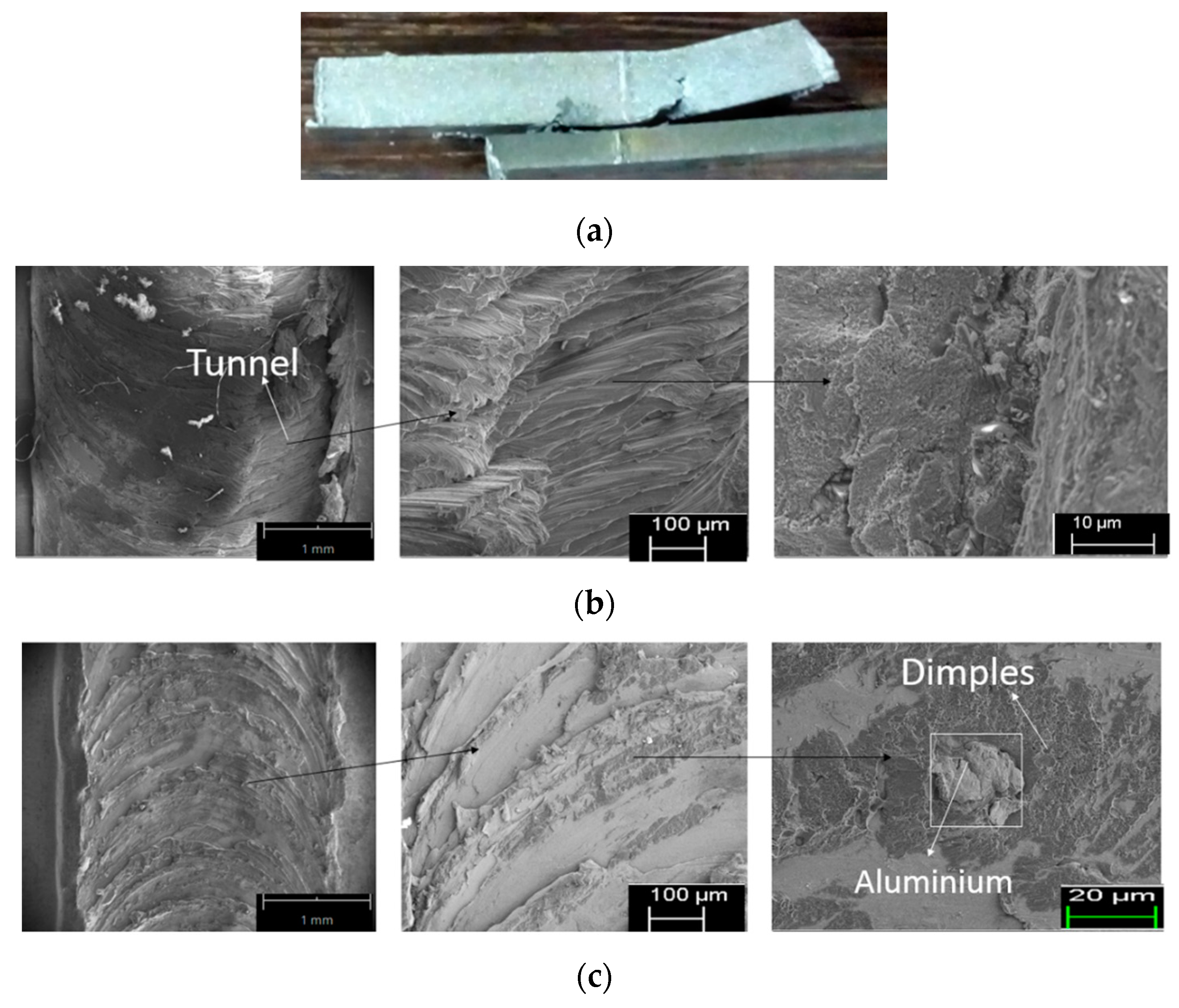
When the AA5052 and SS304 were welded at 0° tilt angle, the fracture was in the tunnel defect area, as shown in Figure 12a. The fracture was mainly on the aluminum side, with a brittle failure on at the edges of the nugget zone on both the advancing side and retreating side. It is evident from the fracture zone that on the aluminum side, the grains were peeled off, which led to the brittle fracture. Meanwhile, on the steel side, as shown in Figure 12b, the aluminum is deposited in the form of small precipitates in the stirred zone, and dimples were formed, which is a mixture of both brittle and ductile failure. The brittle precipitates are formed because of the uneven heat distribution which leads to improper mixing of the material.
3.4.2. Fracture Surface of the Lap Joints Welded at 1.5° Tilt Angle
When the AA5052 and SS304 plates were welded at 1.5 tilt angle, there was a cleavage formed in the stir zone on the aluminum side, as shown in Figure 13a, which confirms that the fracture is the result of brittle failure and it is a quasi-cleavage fracture. The brittle precipitates are unevenly distributed in the stir zone because of void defects at the interfacial region. From Figure 13b, it is evident that fracture on the steel side demonstrates both brittle and ductile failure. The fracture surface on the steel side shows that small dimples are formed along with cracks on the grain boundaries that show ductile failure. The presence of dimples is because of the dimpled intergranular fracture, which is caused by the micro-void nucleation. The dimples formed in the steel side are smaller and occupy more area when compared to the dimples formed with 0° tilt angle, because of better mechanical mixing of aluminum and steel.
3.4.3. Fracture Surface of the Lap Joints Welded at 2.5° Tilt Angle
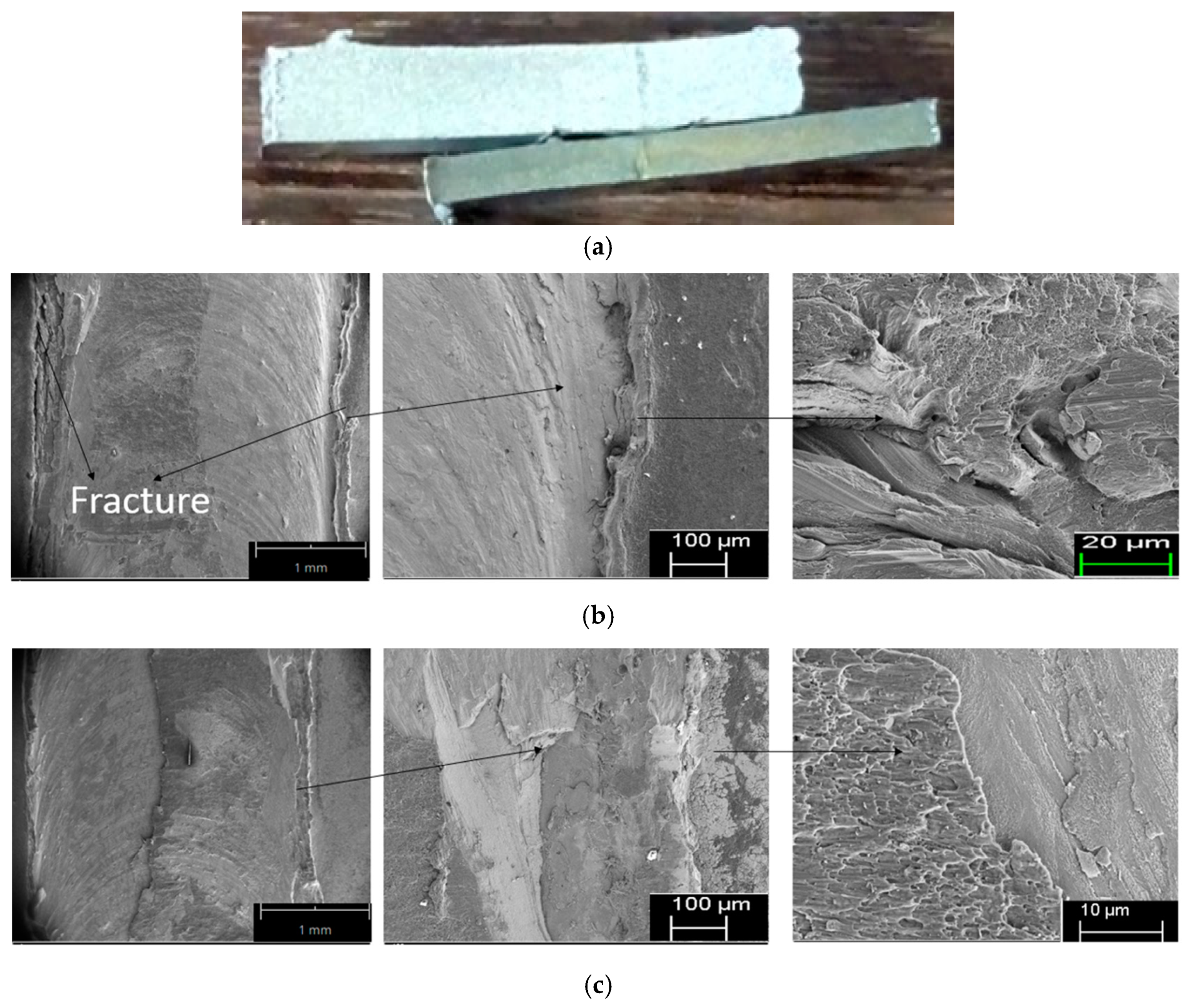
It is evident from Figure 14a,b that the stirred zone is much smoother when AA5052 and SS304 are welded at 2.5° tilt angle. The fracture surface shows that the fracture occurred at the edges of the nugget zone where the hooks were formed at the interfacial region. The fracture surface on the aluminum side is shown in Figure 14a; the fracture surface shows the formation of dimples, cleavage, and the cracks at the grain boundaries, which indicate that the fracture is both brittle and ductile. The dimples formed on the steel side are shown in Figure 14b, which are denser when compared to the samples welded at 0° tilt angle and 1.5° tilt angle, which is a sign of ductile failure on the steel side. Alongside the larger size of the dimples, the cracks are observed unevenly cutting through the grains, which is a trans-granular fracture.
4. Conclusions
In conclusion, this study highlights the investigation of weld surface, interfacial region, mechanical properties, and fracture surface of friction stir welded AA5052 and SS304 plates
- FESEM analysis confirmed that the interfacial region is defect-free when the welds are performed at 2.5° tilt angle and a stable IMC layer. The thickness of the IMC layer formed with 800 and 1000 rpm is between 2.5 and 3 μm, which resulted in achieving better joint strength when compared to the 4.5 μm IMC layer formed with 1200 rpm.
- XRD analysis further helped in detecting the IMCs formed in the weld zone. AlFe AlFe3, Al13Fe4, and Al5Fe2 are the IMCs detected in the interfacial region of the welds. Among the IMCs detected, AlFe and Al13Fe4 are the stable IMCs formed.
- The maximum hardness of 624 HV was achieved with sample LW-4, which is a defect-free joint. The increase in hardness is approximately around 250% when compared to the SS304 base metal. The increase in hardness value ranges (300–630) HV supports the presence of AlFe and AlFe3 intermetallic compounds.
- Tilt angle and penetration depth are the most important factors in determining the shear strength. The maximum shear strength of 3.16 kN was achieved at 2.5° tilt angle with a penetration depth of 4.3 mm when a thin IMC layer was formed.
- Fracture surface analysis of the samples found that the fracture occurred on either side of the nugget zone. FESEM analysis conducted at different tilt angles shows that the fracture formed is both brittle and ductile. Three types of fracture, namely quasi-cleavage, trans-granular, and intergranular, were observed at different fracture zones.
Author Contributions
The research work was carried out under the supervision of S.R.P. and M.A. The resources for the research were procured by S.R.P. The methodology, experiments, characterization and other tests were carried out by V.C. The original draft was written by V.C.; S.R.P., and M.A. contributed their suggestions in reviewing and editing the manuscript. All authors have read and agreed to the published version of the manuscript.
Funding
This research received no external funding.
Acknowledgments
The work was supported by the Centre of Graduate Studies and YUTP grant with cost centre 015LC0-185, Universiti Teknologi PETRONAS, Malaysia.
Conflicts of Interest
The authors declare no conflict of interest.
References
- Wan, L.; Huang, Y. Friction stir welding of dissimilar aluminum alloys and steels: A review. Int. J. Adv. Manuf. Technol. 2018, 99, 1781–1811. [Google Scholar] [CrossRef]
- Mehta, K.P. A review on friction-based joining of dissimilar aluminum–steel joints. J. Mater. Res. 2018, 34, 78–96. [Google Scholar] [CrossRef] [Green Version]
- Chitturi, V.; Pedapati, S.; Awang, M. Challenges in dissimilar friction stir welding of aluminum 5052 and 304 stainless steel alloys. Mater. Werkst. 2020, 51, 811–816. [Google Scholar] [CrossRef]
- Patel, D.; Jani, S. Techniques to weld similar and dissimilar materials by ATIG welding—An overview. Mater. Manuf. Process. 2020, 1–16. [Google Scholar] [CrossRef]
- Kashaev, N.; Ventzke, V.; Çam, G. Prospects of laser beam welding and friction stir welding processes for aluminum airframe structural applications. J. Manuf. Process. 2018, 36, 571–600. [Google Scholar] [CrossRef]
- Gullino, A.; Matteis, P.; D’Aiuto, F. Review of aluminum-to-steel welding technologies for car-body applications. Metals 2019, 9, 315. [Google Scholar] [CrossRef] [Green Version]
- Wang, P.; Chen, X.; Pan, Q.; Madigan, B.; Long, J. Laser welding dissimilar materials of aluminum to steel: An overview. Int. J. Adv. Manuf. Technol. 2016, 87, 3081–3090. [Google Scholar] [CrossRef]
- Springer, H.; Kostka, A.; Payton, E.J.; Raabe, D.; Kaysser-Pyzalla, A.; Eggeler, G. On the formation and growth of intermetallic phases during interdiffusion between low-carbon steel and aluminum alloys. Acta Mater. 2011, 59, 1586–1600. [Google Scholar] [CrossRef]
- Derazkola, H.A.; Khodabakhshi, F. Intermetallic compounds (IMCs) formation during dissimilar friction-stir welding of AA5005 aluminum alloy to St-52 steel: Numerical modeling and experimental study. Int. J. Adv. Manuf. Technol. 2018, 100, 2401–2422. [Google Scholar] [CrossRef]
- Springer, H.; Kostka, A.; Dos Santos, J.; Raabe, D. Influence of intermetallic phases and Kirkendall-porosity on the mechanical properties of joints between steel and aluminium alloys. Mater. Sci. Eng. A 2011, 528, 4630–4642. [Google Scholar] [CrossRef]
- Mahto, R.P.; Kumar, R.; Pal, S.K. Characterizations of weld defects, intermetallic compounds and mechanical properties of friction stir lap welded dissimilar alloys. Mater. Charact. 2020, 160, 110115. [Google Scholar] [CrossRef]
- Anaman, S.Y.; Cho, H.-H.; Das, H.; Lee, J.-S.; Hong, S.-T. Microstructure and mechanical/electrochemical properties of friction stir butt welded joint of dissimilar aluminum and steel alloys. Mater. Charact. 2019, 154, 67–79. [Google Scholar] [CrossRef]
- Liu, Y.; Zhao, H.; Peng, Y.; Ma, X. Microstructure characterization and mechanical properties of the continuous-drive axial friction welded aluminum/stainless steel joint. Int. J. Adv. Manuf. Technol. 2019, 104, 4399–4408. [Google Scholar] [CrossRef]
- Elyasi, M.; Derazkola, H.A.; Hosseinzadeh, M. Investigations of tool tilt angle on properties friction stir welding of A441 AISI to AA1100 aluminium. Proc. Inst. Mech. Eng. Part B J. Eng. Manuf. 2016, 230, 1234–1241. [Google Scholar] [CrossRef]
- Kimapong, K.; Watanabe, T. Lap joint of A5083 aluminum alloy and SS400 Steel by friction stir welding. Mater. Trans. 2005, 46, 835–841. [Google Scholar] [CrossRef] [Green Version]
- Wan, L.; Huang, Y. Microstructure and mechanical properties of Al/steel friction stir lap weld. Metals 2017, 7, 542. [Google Scholar] [CrossRef] [Green Version]
- Li, S.; Chen, Y.; Kang, J.; Amirkhiz, B.S.; Nadeau, F. Effect of revolutionary pitch on interface microstructure and mechanical behavior of friction stir lap welds of AA6082-T6 to galvanized DP800. Metals 2018, 8, 925. [Google Scholar] [CrossRef]
- Pourali, M.; Abdollah-Zadeh, A.; Saeid, T.; Kargar, F. Influence of welding parameters on intermetallic compounds formation in dissimilar steel/aluminum friction stir welds. J. Alloys Compd. 2017, 715, 1–8. [Google Scholar] [CrossRef]
- Tanaka, T.; Nezu, M.; Uchida, S.; Hirata, T. Mechanism of intermetallic compound formation during the dissimilar friction stir welding of aluminum and steel. J. Mater. Sci. 2019, 55, 3064–3072. [Google Scholar] [CrossRef]
- Murugan, B.; Thirunavukarasu, G.; Kundu, S.; Kailas, S.V.; Chatterjee, S. Interfacial microstructure and mechanical properties of friction stir welded joints of commercially pure aluminum and 304 stainless steel. J. Mater. Eng. Perform. 2018, 27, 2921–2931. [Google Scholar] [CrossRef]
- Balamagendiravarman, M.; Kundu, S.; Chatterjee, S. An analysis of microstructure and mechanical properties on friction stir welded joint of dissimilar 304 stainless steel and commercially pure aluminium. Arch. Met. Mater. 2017, 62, 1813–1817. [Google Scholar] [CrossRef] [Green Version]
- Picot, F.; Gueydan, A.; Martinez, M.; Moisy, F.; Hug, E. A Correlation between the ultimate shear stress and the thickness affected by intermetallic compounds in friction stir welding of dissimilar aluminum alloy–stainless steel joints. Metals 2018, 8, 179. [Google Scholar] [CrossRef] [Green Version]
- Dehghani, M.; Amadeh, A.; Mousavi, S.A. Investigations on the effects of friction stir welding parameters on intermetallic and defect formation in joining aluminum alloy to mild steel. Mater. Des. 2013, 49, 433–441. [Google Scholar] [CrossRef]
- Elnabi, M.M.A.; Osman, T.; El Mokadem, A.; Elshalakany, A.B. Evaluation of the formation of intermetallic compounds at the intermixing lines and in the nugget of dissimilar steel/aluminum friction stir welds. J. Mater. Res. Technol. 2020, 9, 10209–10222. [Google Scholar] [CrossRef]
- Mahto, R.P.; Anishetty, S.; Sarkar, A.; Mypati, O.; Pal, S.K.; Majumdar, J.D. Interfacial microstructural and corrosion characterizations of friction stir welded AA6061-T6 and AISI304 materials. Met. Mater. Int. 2018, 25, 752–767. [Google Scholar] [CrossRef]
- Mostafapour, A.; Jamalian, H.M.; Bolghari, A.J.; Chamanara, A. Comprehensive investigation into the dissimilar friction stir welding of Al 2024 to St37. Int. J. Adv. Manuf. Technol. 2017, 93, 3599–3613. [Google Scholar] [CrossRef]
- Nishida, T.; Ogura, T.; Fujimoto, M.; Takahashi, M.; Hirose, A. Formation of interfacial microstructure in a friction stir welded lap joint between aluminium alloy and stainless steel. Sci. Technol. Weld. Join. 2014, 19, 609–616. [Google Scholar] [CrossRef]
- Zhou, L.; Yu, M.; Liu, B.; Zhang, Z.; Liu, S.; Song, X.; Zhao, H. Microstructure and mechanical properties of Al/steel dissimilar welds fabricated by friction surfacing assisted friction stir lap welding. J. Mater. Res. Technol. 2020, 9, 212–221. [Google Scholar] [CrossRef]
- López, E.A.T.; Ramirez, A.J. Effect of process parameters in obtaining aluminium–steel joints and their microstructure by friction stir welding (FSW). Weld. Int. 2014, 29, 689–697. [Google Scholar] [CrossRef]
- Zhao, S.; Ni, J.; Wang, G.; Wang, Y.; Bi, Q.; Zhao, Y.; Liu, X. Effects of tool geometry on friction stir welding of AA6061 to TRIP steel. J. Mater. Process. Technol. 2018, 261, 39–49. [Google Scholar] [CrossRef]
- Zandsalimi, S.; Heidarzadeh, A.; Saeid, T. Dissimilar friction-stir welding of 430 stainless steel and 6061 aluminum alloy: Microstructure and mechanical properties of the joints. Proc. Inst. Mech. Eng. Part L J. Mater. Des. Appl. 2018, 233, 1791–1801. [Google Scholar] [CrossRef]
- Shen, Z.; Chen, Y.; Haghshenas, M.; Gerlich, A. Role of welding parameters on interfacial bonding in dissimilar steel/aluminum friction stir welds. Eng. Sci. Technol. Int. J. 2015, 18, 270–277. [Google Scholar] [CrossRef] [Green Version]
- Helal, Y.; Boumerzoug, Z.; Fellah, L. Microstructural evolution and mechanical properties of dissimilar friction stir lap welding aluminum alloy 6061-T6 to ultra low carbon steel. Energy Procedia 2019, 157, 208–215. [Google Scholar] [CrossRef]
- Mahto, R.P.; Gupta, C.; Kinjawadekar, M.; Meena, A.; Pal, S.K. Weldability of AA6061-T6 and AISI 304 by underwater friction stir welding. J. Manuf. Process. 2019, 38, 370–386. [Google Scholar] [CrossRef]
- Bement, T.R.; Ross, P.J. Taguchi techniques for quality engineering. Technometrics 1989, 31, 254. [Google Scholar] [CrossRef]
- Chitturi, V.; Pedapati, S.R.; Awang, M. Effect of tilt angle and pin depth on dissimilar friction stir lap welded joints of aluminum and steel alloys. Materials 2019, 12, 3901. [Google Scholar] [CrossRef] [Green Version]
- Figner, M.G.; Vallant, R.; Weinberger, M.T.; Enzinger, N.; Schröttner, H.; Paśič, H. Friction stir spot welds between aluminium and steel automotive sheets: Influence of welding parameters on mechanical properties and microstructure. Weld. World 2009, 53, R13–R23. [Google Scholar] [CrossRef]
- Cahn, R.W. Binary Alloy Phase Diagrams, 2nd ed.; Massalski, T.B., Okamoto, H., Subramanian, P.R., Kacprzak, L., Eds.; ASM International: Materials Park, OH, USA, 1990; Volume 3. [Google Scholar] [CrossRef]
- Gu, J.; Gu, S.; Xue, L.; Wu, S.; Yan, Y. Microstructure and mechanical properties of in-situ Al13Fe4/Al composites prepared by mechanical alloying and spark plasma sintering. Mater. Sci. Eng. A 2012, 558, 684–691. [Google Scholar] [CrossRef]
- Movahedi, M.; Kokabi, A.; Reihani, S.S.; Najafi, H.; Farzadfar, S.; Cheng, W.; Wang, C. Growth kinetics of Al–Fe intermetallic compounds during annealing treatment of friction stir lap welds. Mater. Charact. 2014, 90, 121–126. [Google Scholar] [CrossRef]
- Basariya, M.I.R.; Mukhopadhyay, N.K. Structural and Mechanical Behaviour of Al-Fe Intermetallics. Intermet. Compd. Form. Appl. 2018. [Google Scholar] [CrossRef] [Green Version]
Figure 1.
Schematic representation of dissimilar friction stir lap welding.

Figure 2.
Welded surface of the samples at different tool tilt angles: (a) 0° tilt angle; (b) 1.5° tilt angle; (c) 2.5° tilt angle.
Figure 2.
Welded surface of the samples at different tool tilt angles: (a) 0° tilt angle; (b) 1.5° tilt angle; (c) 2.5° tilt angle.

Figure 3.
FESEM images of the welded region at 0° tilt angle: (a) Macrostructure; (b) Microstructure.
Figure 3.
FESEM images of the welded region at 0° tilt angle: (a) Macrostructure; (b) Microstructure.

Figure 4.
EDS spectrum analysis and element mapping of the welded samples at 0° tilt angle: (a) Electron image; (b) Al mapping; (c) Fe mapping; (d) EDS point 1; (e) EDS point 2; (f) EDS point 3.
Figure 4.
EDS spectrum analysis and element mapping of the welded samples at 0° tilt angle: (a) Electron image; (b) Al mapping; (c) Fe mapping; (d) EDS point 1; (e) EDS point 2; (f) EDS point 3.

Figure 5.
FESEM images of the welded region at 1.5° tilt angle: (a) Macrostructure; (b) Microstructure.
Figure 5.
FESEM images of the welded region at 1.5° tilt angle: (a) Macrostructure; (b) Microstructure.

Figure 6.
EDS spectrum analysis and element mapping of the welded samples at 1.5° tilt angle: (a) Electron image; (b) Al mapping; (c) Fe mapping; (d) EDS point 1; (e) EDS point 2; (f) EDS point 3.
Figure 6.
EDS spectrum analysis and element mapping of the welded samples at 1.5° tilt angle: (a) Electron image; (b) Al mapping; (c) Fe mapping; (d) EDS point 1; (e) EDS point 2; (f) EDS point 3.

Figure 7.
FESEM images of the welded region at 2.5° tilt angle: (a) IMC layer of sample LW-3; (b) IMC layer of Sample LW-4; (c) IMC layer of sample LW-8.
Figure 7.
FESEM images of the welded region at 2.5° tilt angle: (a) IMC layer of sample LW-3; (b) IMC layer of Sample LW-4; (c) IMC layer of sample LW-8.

Figure 8.
EDS spectrum analysis and element mapping of the welded samples at 2.5° tilt angle: (a) Electron image; (b) Al mapping; (c) Fe mapping; (d) EDS point 1; (e) EDS point 2; (f) EDS point 3.
Figure 8.
EDS spectrum analysis and element mapping of the welded samples at 2.5° tilt angle: (a) Electron image; (b) Al mapping; (c) Fe mapping; (d) EDS point 1; (e) EDS point 2; (f) EDS point 3.

Figure 9.
XRD analysis of the interfacial region of the lap joints welded at different tilt angles: (a) 0° tilt angle; (b) 1.5° tilt angle; (c) 2.5° tilt angle.
Figure 9.
XRD analysis of the interfacial region of the lap joints welded at different tilt angles: (a) 0° tilt angle; (b) 1.5° tilt angle; (c) 2.5° tilt angle.

Figure 10.
Shear strength of the lap joints: (a) 0° tilt angle; (b) 1.5° tilt angle; (c) 2.5° tilt angle.
Figure 10.
Shear strength of the lap joints: (a) 0° tilt angle; (b) 1.5° tilt angle; (c) 2.5° tilt angle.

Figure 11.
Hardness of the lap joints: (a) 0° tilt angle; (b) 1.5° tilt angle; (c) 2.5° tilt angle.

Figure 12.
Fracture surface images of the FSLW joints at 0° tool tilt angle. (a) Fracture; (b) Fracture zone on aluminum side; (c) Fracture zone on steel side.
Figure 12.
Fracture surface images of the FSLW joints at 0° tool tilt angle. (a) Fracture; (b) Fracture zone on aluminum side; (c) Fracture zone on steel side.

Figure 13.
Fracture surface images of the FSLW at 1.5° tool tilt angle. (a) Fracture; (b) Fracture on aluminum side; (c) Fracture on steel side.
Figure 13.
Fracture surface images of the FSLW at 1.5° tool tilt angle. (a) Fracture; (b) Fracture on aluminum side; (c) Fracture on steel side.

Figure 14.
Fracture surface images of the FSLW joints at 2.5° tool tilt angle. (a) Fracture; (b)Fracture on aluminum side; (c) Fracture on steel side.
Figure 14.
Fracture surface images of the FSLW joints at 2.5° tool tilt angle. (a) Fracture; (b)Fracture on aluminum side; (c) Fracture on steel side.


Table 1.
Process parameters and their levels.
| Parameters | Tool Rotational Speed (rpm) | Welding Speed (mm/min) | Penetration Depth (mm) | Tilt Angle (°) |
|---|---|---|---|---|
| Level 1 | 800 | 20 | 4.1 | 0 |
| Level 2 | 1000 | 30 | 4.2 | 1.5 |
| Level 3 | 1200 | 40 | 4.3 | 2.5 |
Table 2.
Taguchi L9 orthogonal array for three levels.
| Exp No. | Tool Rotational Speed | Welding Speed | Penetration Depth | Tilt Angle |
|---|---|---|---|---|
| LW-1 | 1 | 1 | 1 | 1 |
| LW-2 | 1 | 2 | 2 | 2 |
| LW-3 | 1 | 3 | 3 | 3 |
| LW-4 | 2 | 1 | 2 | 3 |
| LW-5 | 2 | 2 | 3 | 1 |
| LW-6 | 2 | 3 | 1 | 2 |
| LW-7 | 3 | 1 | 3 | 2 |
| LW-8 | 3 | 2 | 1 | 3 |
| LW-9 | 3 | 3 | 2 | 1 |
Table 3.
Mechanical properties of the base materials.
| Properties | Micro Hardness (HV) | Tensile Yield Strength (Mpa) | Ultimate Tensile Strength (MPa) | Elongation (%) |
|---|---|---|---|---|
| AA5052 | 68 | 193 | 228 | 12 |
| SS304 | 129 | 215 | 505 | 70 |
Publisher’s Note: MDPI stays neutral with regard to jurisdictional claims in published maps and institutional affiliations. |
© 2020 by the authors. Licensee MDPI, Basel, Switzerland. This article is an open access article distributed under the terms and conditions of the Creative Commons Attribution (CC BY) license (http://creativecommons.org/licenses/by/4.0/).
Share and Cite
MDPI and ACS Style
Chitturi, V.; Pedapati, S.R.; Awang, M. Investigation of Weld Zone and Fracture Surface of Friction Stir Lap Welded 5052 Aluminum Alloy and 304 Stainless Steel Joints. Coatings 2020, 10, 1062. https://doi.org/10.3390/coatings10111062
AMA Style
Chitturi V, Pedapati SR, Awang M. Investigation of Weld Zone and Fracture Surface of Friction Stir Lap Welded 5052 Aluminum Alloy and 304 Stainless Steel Joints. Coatings. 2020; 10(11):1062. https://doi.org/10.3390/coatings10111062
Chicago/Turabian StyleChitturi, Veerendra, Srinivasa Rao Pedapati, and Mokhtar Awang. 2020. "Investigation of Weld Zone and Fracture Surface of Friction Stir Lap Welded 5052 Aluminum Alloy and 304 Stainless Steel Joints" Coatings 10, no. 11: 1062. https://doi.org/10.3390/coatings10111062
Note that from the first issue of 2016, this journal uses article numbers instead of page numbers. See further details here.