
Analytical Model of Deformation of a Functionally Graded Ceramic Coating under Local Load


1
Laboratory of Modeling of Damping Systems, Pidstryhach Institute for Applied Problems in Mechanics and Mathematics, National Academy of Sciences of Ukraine, Mykytynetska Str. 3, 76002 Ivano-Frankivsk, Ukraine
2
Department of Computerized Engineering, Ivano-Frankivsk National Technical University of Oil and Gas, 15 Karpatska Str., 76019 Ivano-Frankivsk, Ukraine
3
Department of Construction and Civil Engineering, Ivano-Frankivsk National Technical University of Oil and Gas, 15 Karpatska Str., 76019 Ivano-Frankivsk, Ukraine
*
Author to whom correspondence should be addressed.
Ceramics 2023, 6(3), 1879-1893; https://doi.org/10.3390/ceramics6030115
Submission received: 31 May 2023
/
Revised: 24 August 2023
/
Accepted: 5 September 2023
/
Published: 7 September 2023
Abstract
:In this article, an analytical approach to the study of the behavior of functionally graded FG coatings under local load is developed. The method is suitable for coatings with a specific structure. We consider that the coating can be conditionally divided into two zones: a relatively rigid outer and a relatively compliant inner. The outer layer is modeled by a non-homogeneous plate that bends. We submit the inner substrate to the hypothesis of a non-homogeneous thin Winkler layer. The solution of the formulated boundary value problem is constructed in analytical form. Simulation examples for FG aluminum oxide coatings grown from aluminum sprayed on steel and from compact alloy D16T are considered. The distributions of equivalent stresses, safety factors and normalized equivalent stresses in the coatings are studied. It is noted that in a heterogeneous material, the location of the minimum of the safety factor does not always coincide with the location of the maximum of the equivalent stress.
1. Introduction
Research related to the application and formation of functional coatings is of interest due to the suitability of such coatings to improve the performance properties of structural materials. The traditional approach involves the use of a coating on the base material’s surface to provide protection against environmental influences, contact or local loads; to provide the required aesthetic parameters of the product; etc. [1,2,3,4].
In particular, ceramic coatings are widely used in many industries due to their wear resistance, chemical resistance and thermal properties. Their fields of application vary from instrumental, energy and aviation engineering to medicine and semiconductor manufacturing [5,6,7]. In detail, we note that ceramic coatings include hard coatings, anti-corrosion coatings, wear-resistant coatings and heat-protective coatings, which are often used in engineering today [8]. At the same time, ceramic coatings are an integral part of foundry production. Here, their main role is to form an effective fire-resistant barrier between the sand substrate and the flow of liquid metal at the stages of casting, hardening and forming castings [9,10]. Ceramic coatings have proven themselves well for improving the osteointegration and biomechanical fixation of implants in bone tissue [11,12]. Another important field of application is ceramic functional coatings used in lenses, optical filters and solar cells and catalytic coatings for the chemical industry, which contribute to the development of environmental protection technologies [13,14].
Despite all the advantages of functional coatings, there is the problem of ensuring that they work in extreme operating conditions, for example, in conditions of high temperatures, with intense contact effects or the appearance of local loads [15,16]. The presence of clear interfaces between individual components of the material, which have different coefficients of thermal expansion or values of elastic moduli, can lead to the delamination of components or the appearance of cracks, which causes the destruction of the coating [17,18]. In recent years, a new generation of composite materials has appeared—functional-gradient materials, which are characterized by the absence of clear boundaries between components and a continuous spatial change in physical and mechanical properties. One of the main concepts of creating functional-gradient materials is to obtain a gradient of structures and properties of components, which would reduce the concentration of internal stresses and increase the service life of the material in accordance with operational requirements. In many cases, the presence of a gradient structure of the material makes it possible to develop products with new, previously unknown characteristics [19,20].
To date, significant progress has been made in the study of the behavior and characteristics of the destruction of functional and functional-gradient coatings under the influence of operational loads. The processes of the thermal and thermomechanical destruction of coatings, including those in the presence of cracks, are discussed in the papers [21,22]. The review [23] carried out a critical analysis of studies that provide a fundamental understanding of the strength of functional-gradient coatings under dynamic influences and fatigue loads. In the studies [24,25,26], the authors successfully use the finite element method to estimate the internal stresses that occur during the operation of protective coatings.
In coating systems where intermittent high strain rate contact occurs, such as interrupted high-performance machining operations, impact resistance can be critical to serviceability. In the works [27,28], the principles of operation of the technique for carrying out nano-, micro- and macroscale impact tests of coatings are considered. The peculiarities of the determination of wear resistance in the conditions of field tests for abrasion and shock-abrasive wear and the measurement of hardness using indentation are considered in the publications [29,30]. The detailed review [31] presents a portfolio of methods for determining the microstructural, mechanical and thermophysical characteristics of solid coatings, which allow an understanding of the relationships between the structure and properties of the coating. The results of the analysis of the behavior and reinforcing effect of thin coatings and overlays applied to slabs with defects [32,33,34,35] and shells with cracks [36,37] are of important applied value. In this direction, researchers also studied the patterns of development of operational damage in coatings [38,39] and developed technologies for healing cracks by injecting pliable [40,41,42] and non-contrast [43] fillers.
Rather often, the initiation of the gradient coating destruction is caused by contact or localized loads. Therefore, in the last decade, the analysis of mechanical stresses in protective coatings caused by contact pressure has been the subject of research by many scientists [44,45,46,47,48]. These papers demonstrate the effects of factors such as coating stiffness, friction coefficient and contact geometry on the stress state of coatings and substrates.
One of the fundamental ways to improve the operational properties of products made of aluminum alloys is to modify the working surface of the product by plasma electrolytic oxidation (PEO) in order to transform the surface layer into a hard, wear-resistant and heat-resistant oxyceramic [49]. In general, plasma electrolytic oxidation is an effective technological method of forming protective oxide coatings on aluminum and its alloys [50,51], as well as on metals and alloys of metals of the valve group, for example, magnesium or titanium [52,53,54]. The use of the PEO method ensures a reliable (metallurgical) connection between the base material and the coating.
To obtain oxide coatings on parts made of steel and other structural materials, a layer of aluminum is first applied to their working surface and its mechanical processing (turning, milling, grinding, etc.) is carried out. After that, the upper part of the aluminum layer is oxidized, turning it into a ceramic, and the lower part (sublayer) is left unoxidized. The PEO process is carried out in an electrolyte [55]. Due to the course of plasma-chemical reactions in the discharge channels, dispersed oxides are formed, which contain different phases in their composition, including high-temperature [48,56].
The properties of the formed inhomogeneous coating can arbitrarily change in a certain spatial direction. Traditionally, problems concerning the theory of elasticity for a heterogeneous medium are described by a system of partial differential equations with variable coefficients. Analytical solutions of such equations are known only for certain cases of canonical domains and laws of change of elastic moduli in space [57,58,59] and do not have a standard approach.
To develop analytical methods for assessing the stress state of layered coatings under local load, the authors of this article in their previous publications developed a methodological approach based on one-dimensional modeling of the behavior of a layered coating under an arbitrarily oriented local load [60], in particular when interacting with fixed or unfixed abrasive particles [61]. The main feature of this approach is as follows: The outer, sufficiently hard part of the coating is modeled as a plate, and the inner (interface), sufficiently soft part of the coating or substrate is considered as a Winkler layer. This technique allows a reduction in the dimensionality of the continuums and usually achieves an analytical result.
The purpose of our article is to spread the analytical method of studying the stress state of a functional-gradient coating under a local load in case of an arbitrary change in its elastic moduli due to thickness. In order to achieve the goal and fulfill the tasks of the work, the article is organized as follows: First of all, the main hypotheses of the analytical model of the FGM coating are presented, and the boundary value problem for a heterogeneous coating under local load is formulated. Then, the analytical solution of the problem is constructed, and robustness conditions are discussed. After that, calculation examples are considered for a non-homogeneous oxide coating grown from PEO aluminum sprayed on steel and for a ceramic coating formed from PEO compact deformed aluminum alloy D16T. Finally, brief conclusions conclude the publication.
2. Materials and Methods
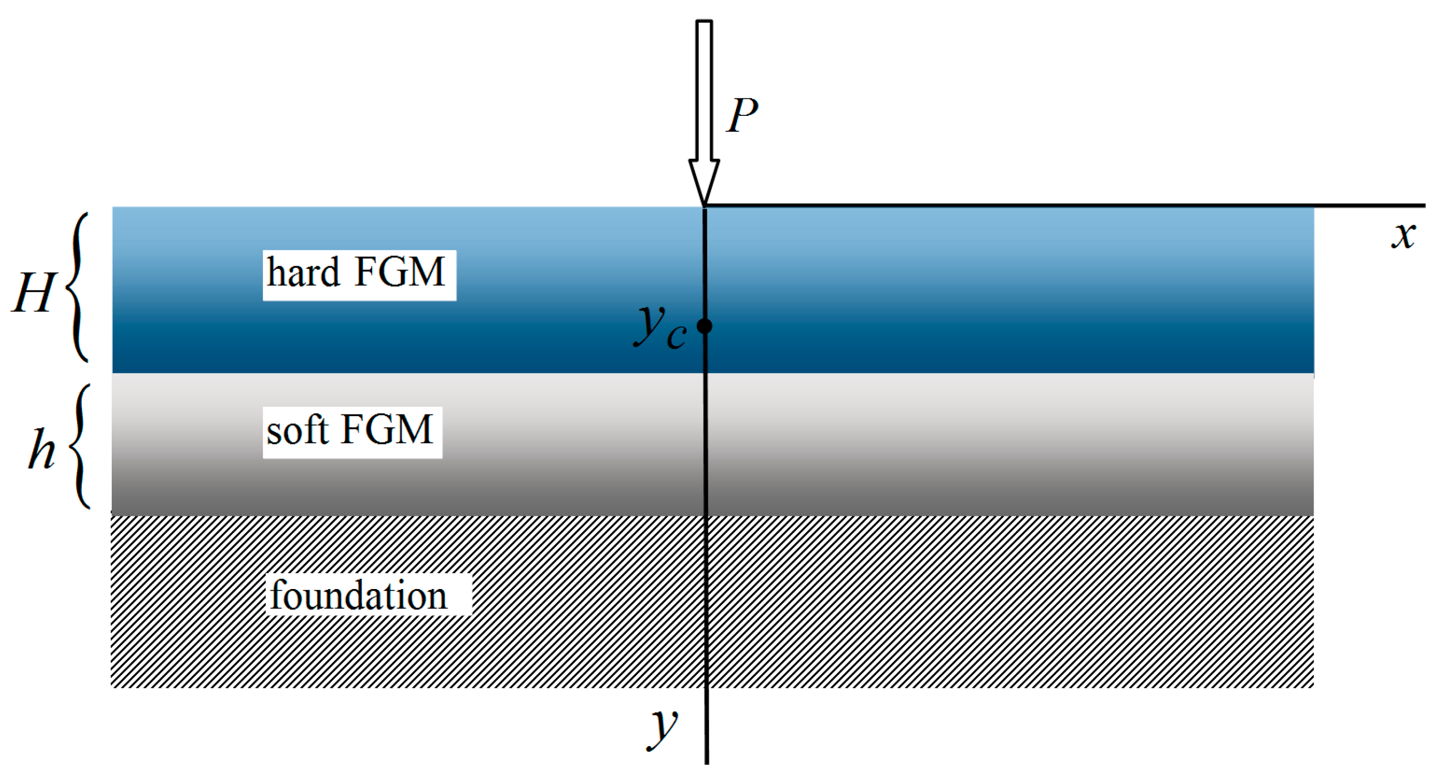
Consider a rigid element of the structure (a foundation) on which a thin coating is applied, consisting of an outer, sufficiently rigid functionally gradient layer and a relatively compliant heterogeneous substrate (Figure 1). This division of a non-homogeneous coating into hard and soft parts is rather arbitrary, but it allows us to develop an analytical research method. From a mechanical point of view, the rigid outer layer is considered as a non-uniform thickness plate, which works for bending, and the pliable inner layer is subject to Winkler’s hypothesis about the proportionality of stresses and elastic displacements. For simplicity, the base is assumed to be absolutely rigid. The mechanical contact between the components on the mating surfaces is assumed to be ideal. The composition is loaded with a normal force (N/m), uniformly distributed along the axis , which is perpendicular to the plane of the drawing. In addition, we assume the state of plane strain (). It is necessary to study the distribution of stresses in a non-homogeneous coating and establish the level of the safety margin.
Let us introduce a system of Cartesian coordinates with the origin on the surface and the axis directed deep into the half-space (Figure 1). Under the accepted assumptions, we will write the equation of equilibrium of a non-uniform coating on an elastic base [62]:
here is the transverse component of the elastic displacement vector of the physically neutral surface of the plate;
is the bending rigidity;
is the ordinate of the location of the physically neutral surface;
is the coefficient of stiffness of a non-homogeneous foundation; , are piecewise continuous functions for Young’s modulus and Poisson’s ratio of the coating material; is the thickness of the rigid layer; is the thickness of the substrate; is the Dirac function.
At infinity, moments and transversal forces must fade:
Thus, the boundary value problem (1) and (5) describes the desired field of vertical movements of the cover plate on an elastic base.
3. Results and Analysis
3.1. Analytical Solution
The solution to problem (1), (5) was found in the form
where is a pinching factor, the dimension of which is the inverse of the length.
According to displacements (5), the bending moment in the coating was determined:
and the contact stress on the hypothetical interface is
Stresses in an inhomogeneous plate are calculated using the following formulae:
and, in the inhomogeneous Winkler layer, according to the formulae
The strength of the functional-gradient coating is evaluated according to the Mises criterion. Therefore, the strength condition for a plane-strained coating will be
here is the equivalent Mises stress, is the allowable stress for a non-homogeneous coating material (, where is yield strength and is the safety factor).
The obtained results make it possible to determine the value of the permissible load, which depends on the mechanical and geometric characteristics of the layered coating.
3.2. Approximation of Functional-Gradient Properties
For the practical simulation of the behavior of ceramic oxide aluminum coatings, a linear approximation of the distribution of their mechanical characteristics over the thickness of the plate was used:
here, at , we have the properties of surface spinels, and at , we have the properties of the -phase near the interface.
For coatings with a developed ceramic phase, we will also use the piecewise linear approximation :
For the characteristics of the compliant substrate, we used linear approximation or constants:
or piecewise constant functions ():
After calculating the quadratures (2), (3) taking into account the approximation (8), we find approximate expressions for the ordinate of the neutral plane and the cylindrical stiffness:
In turn, using approximations (9), we obtained a much more cumbersome result:
In addition, using Formula (4), we find expressions for the bed coefficient that correspond to approximations (10) and (11):
3.3. Calculation Examples
3.3.1. Example 1
To obtain an oxide ceramic coating on parts made of steel or other widely used structural materials, a layer of aluminum is first applied to their working surface and its mechanical processing (turning, milling, grinding, etc.) is carried out. After that, the upper part of the aluminum layer is oxidized, turning it into a functional-gradient ceramic, and the lower part (sublayer of aluminum) is left unoxidized. The PEO procedure is carried out in an electrolyte. The physical and mechanical properties of the obtained oxide coatings depend on the chemical composition of the material applied to the steel base and the electrolyte and on the electrical parameters of the process. It should be noted that, when oxide coatings are obtained, a loose layer is formed on their surface, which consists of low-temperature phases of oxides and spinels formed from the chemical elements of the applied material and the electrolyte. To ensure the quality of the surface of the oxide coating and the accuracy of the geometric dimensions of the parts, the upper loosened layer is removed by mechanical processing with a blade (turning tool , cutter) or an abrasive (grinding wheel) diamond tool. The optimization of these machining processes, as well as the rational operation of finished products, involves consideration of the behavior of the Al–Al2O3 oxide coating on a steel base under the influence of a local load. In this example, we will consider two options: a functionally gradient oxide coating with a linear change in mechanical properties over the entire thickness (FG coating) and a developed ceramic coating with a thin gradient layer on the surface (FG/ceramic coating).
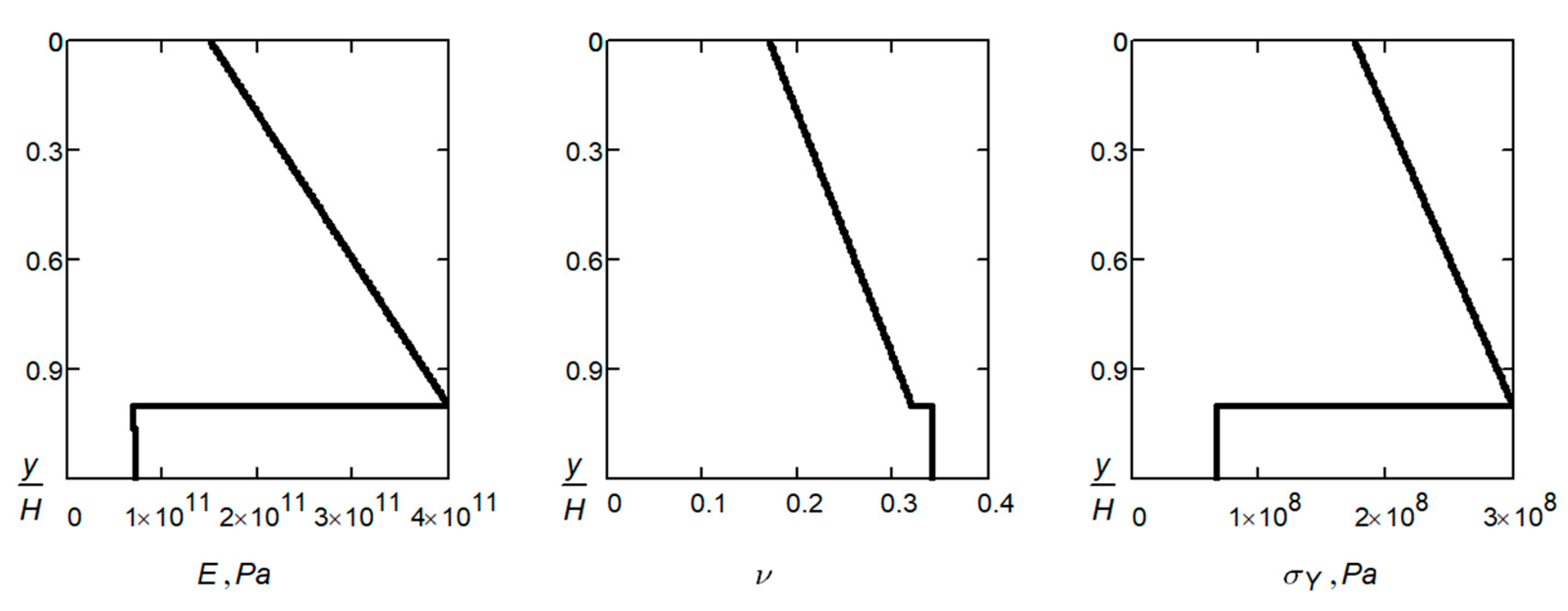
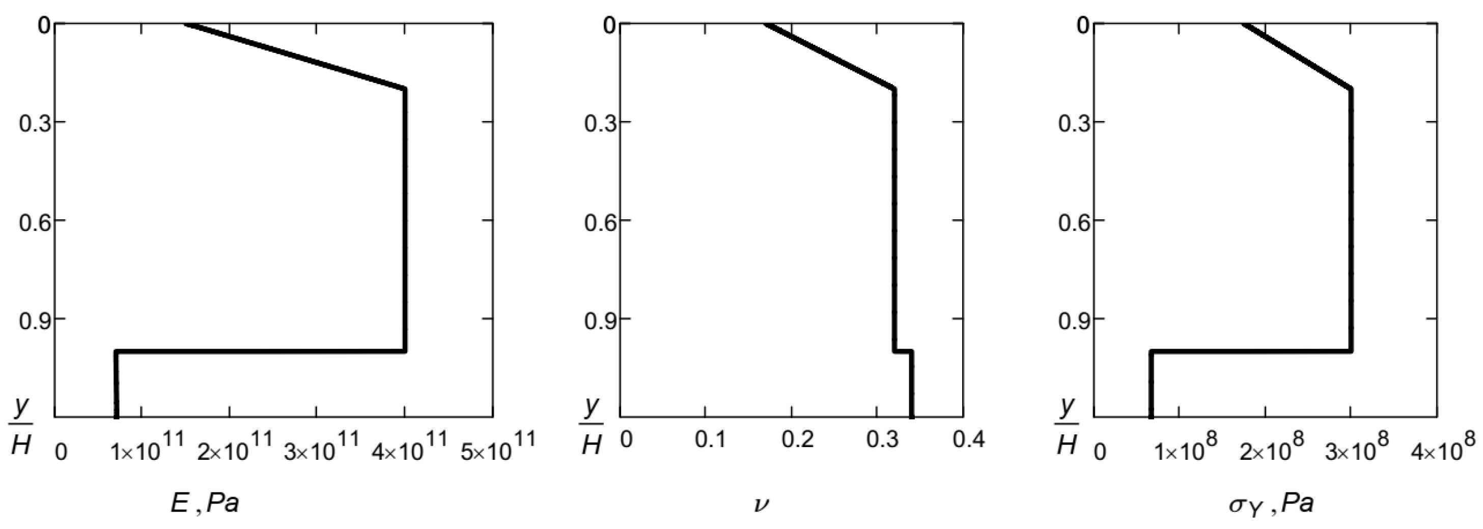
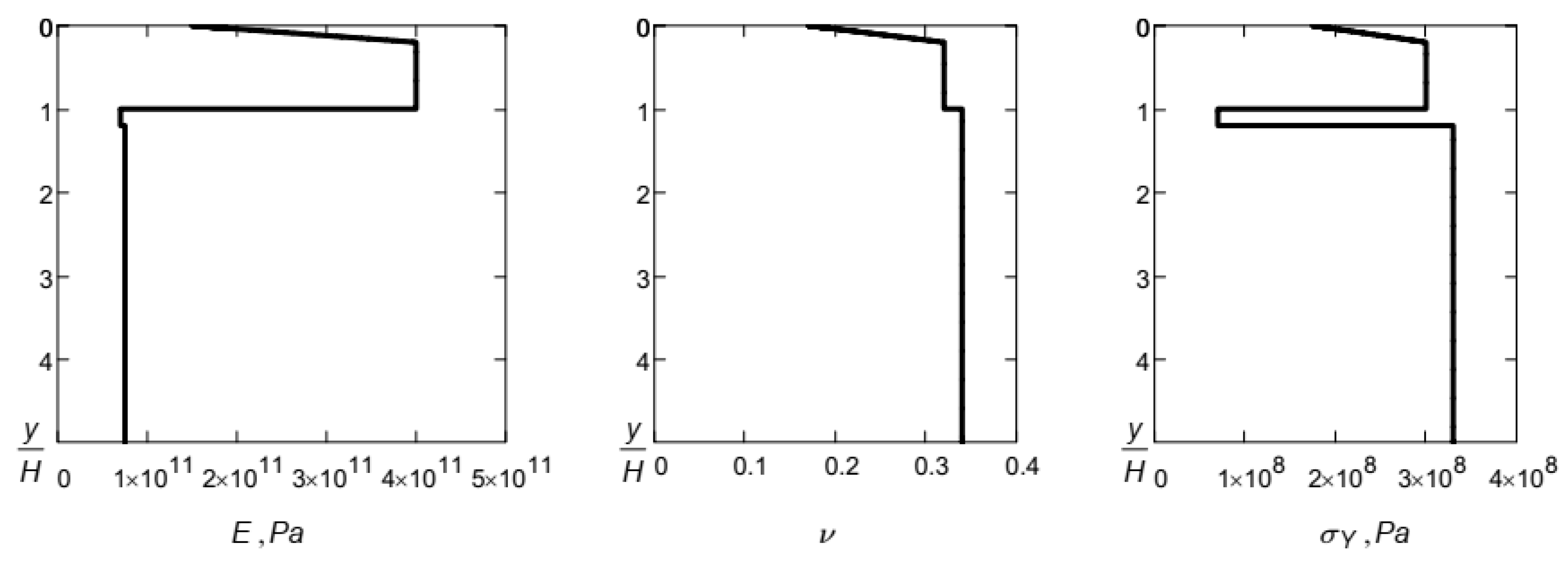
Let us suppose that a layer of aluminum is deposited on a flat steel part, from which a layer is grown by means of plasma electrolytic oxidation Al2O3. The thickness of the heterogeneous oxide layer is μm, the thickness of the aluminum substrate is μm. The reference values for the mechanical characteristics for approximations (8), (10) are presented in Table 1, the distribution of mechanical characteristics by thickness of the composite coating is shown in Figure 2.
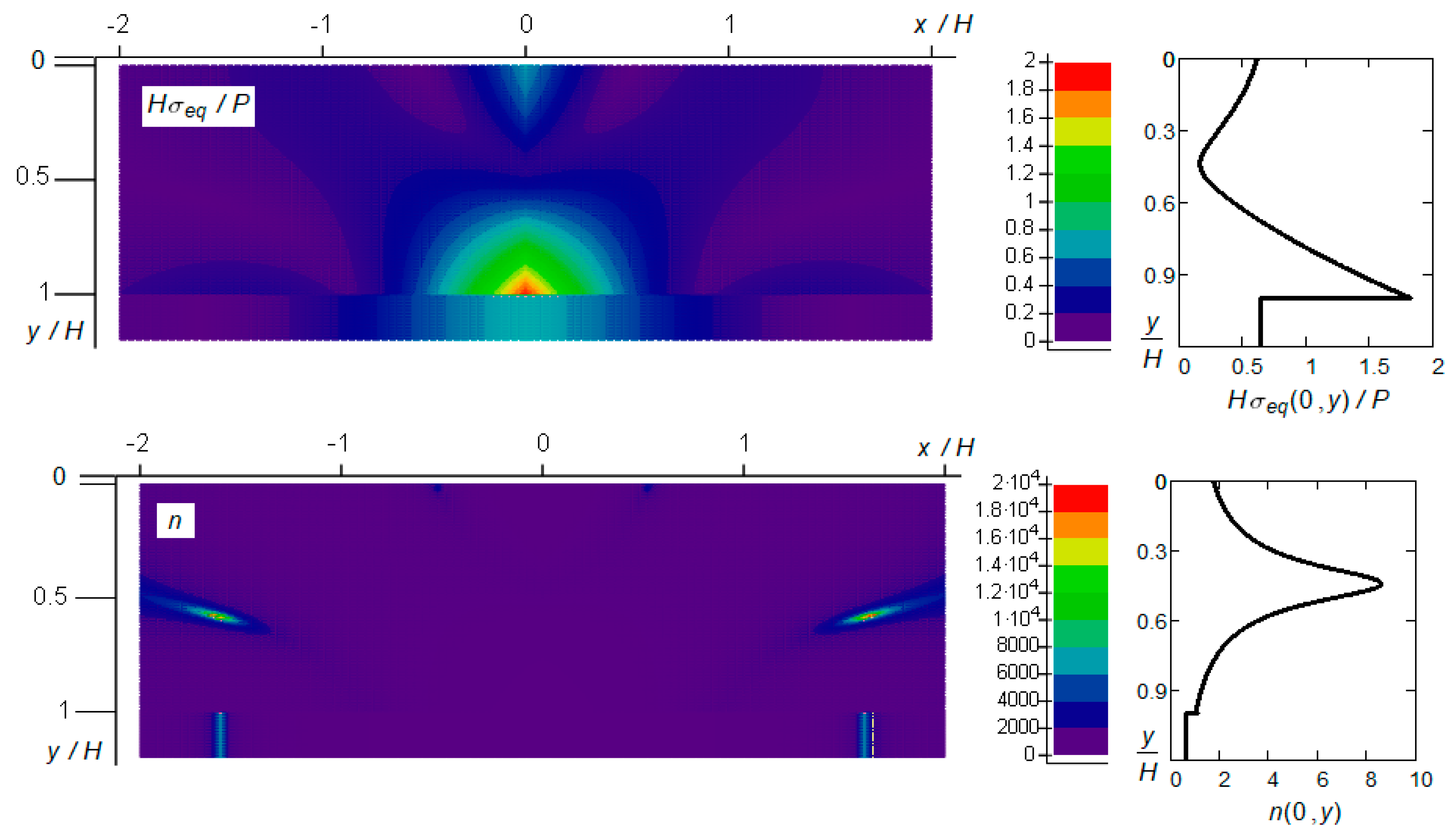
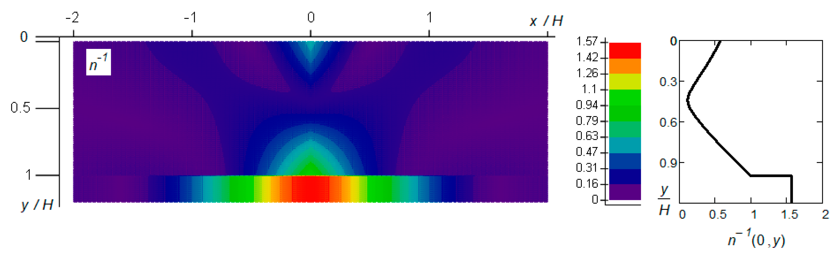
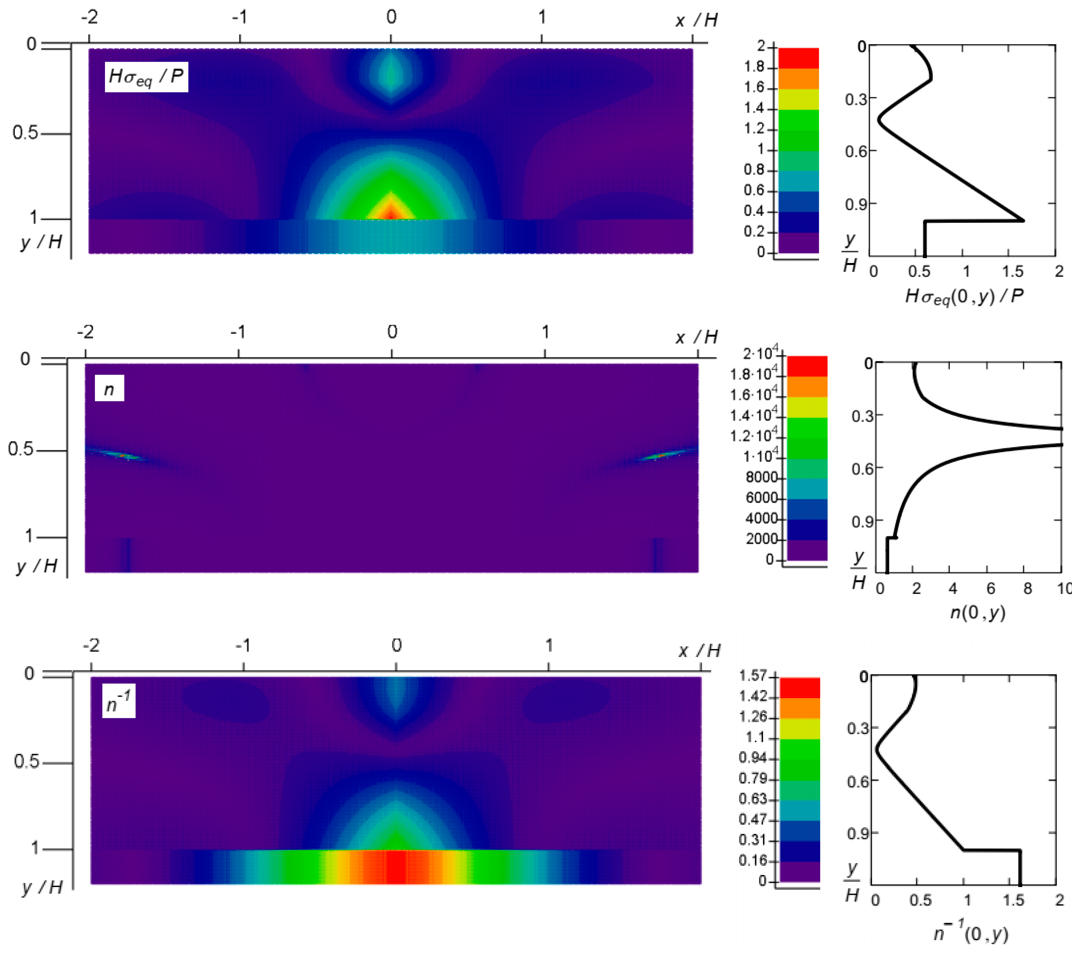
The dimensionless values of equivalent stress were calculated using Formula (7): , as well as the safety factor and its inverse value of the normalized equivalent stresses (Figure 3). We normalized the safety factor so that there; where the equivalent stress reaches a maximum.
As seen from Figure 3, the stressed state is concentrated around the line of application of the concentrated force, and the largest equivalent stresses are observed on the lower face of the oxide layer (on the line ).
We should pay attention to the fact that we are dealing with a non-uniform coating, so, in order to estimate its limit state, we must also take into account the spatial distribution of the strength characteristics (in this case, the value of the yield strength of each layer). Therefore, a more correct characterization of the limit state of a layered coating is provided by the distribution of the safety factor or normalized equivalent stress. Despite the fact that the maximum equivalent stress is reached in the oxide layer, the ultimate equilibrium of the coating will be disturbed first in the aluminum substrate, where the margin ratio is the smallest.
Now, let the oxidized layer of sprayed aluminum consist of a surface gradient layer with a thickness of and high-quality ceramics with a thickness of ; the parameters of the substrate do not change. The reference values for the mechanical characteristics for approximations (9), (10) are given in Table 2. The distribution of mechanical characteristics by thickness of the composite coating is presented in Figure 4, and the characteristics of the stressed and limit states of the composition are shown in Figure 5.
Comparing the data in Figure 3 and Figure 5, we can reveal the influence of the alignment of the mechanical properties of the coating by thickness on the stress state and strength of the coating–substrate system. In particular, the presence of a sufficiently thick ceramic layer increases rigidity and reduces stress in the coating. At the same time, the character of the destruction does not change: the weakest link remains the aluminum substrate, in which the reserve factor practically retains its previous minimum value.
3.3.2. Example 2
A relatively high ratio of yield strength to specific gravity, high thermal conductivity and corrosion resistance are key advantages that make aluminum alloys technologically attractive and cost-effective structural materials. However, in a number of cases, insufficient wear resistance, heat resistance, and vulnerability to thermal shocks remain restraining factors limiting the use of aluminum alloys. In order to use the advantages and eliminate certain disadvantages of aluminum alloys, engineers use PEO technologies for the surface strengthening of aluminum alloys. Aluminum deformed alloy D16T has fairly high mechanical properties compared to other aluminum alloys, and its products are widely used in industry and everyday life. This alloy belongs to the aluminum alloys of the Al–Cu–Mg system, and it is subject to hardening and natural aging. Intermetallics formed in the microstructure are the main factor in the strengthening mechanism of this alloy. However, these intermetallics lead to microelectrochemical inhomogeneity of the alloy, which leads to pitting corrosion, intergranular corrosion or delamination. Therefore, deformed alloys of such a system are used clad with a layer of aluminum and/or subjected to PEO [7].
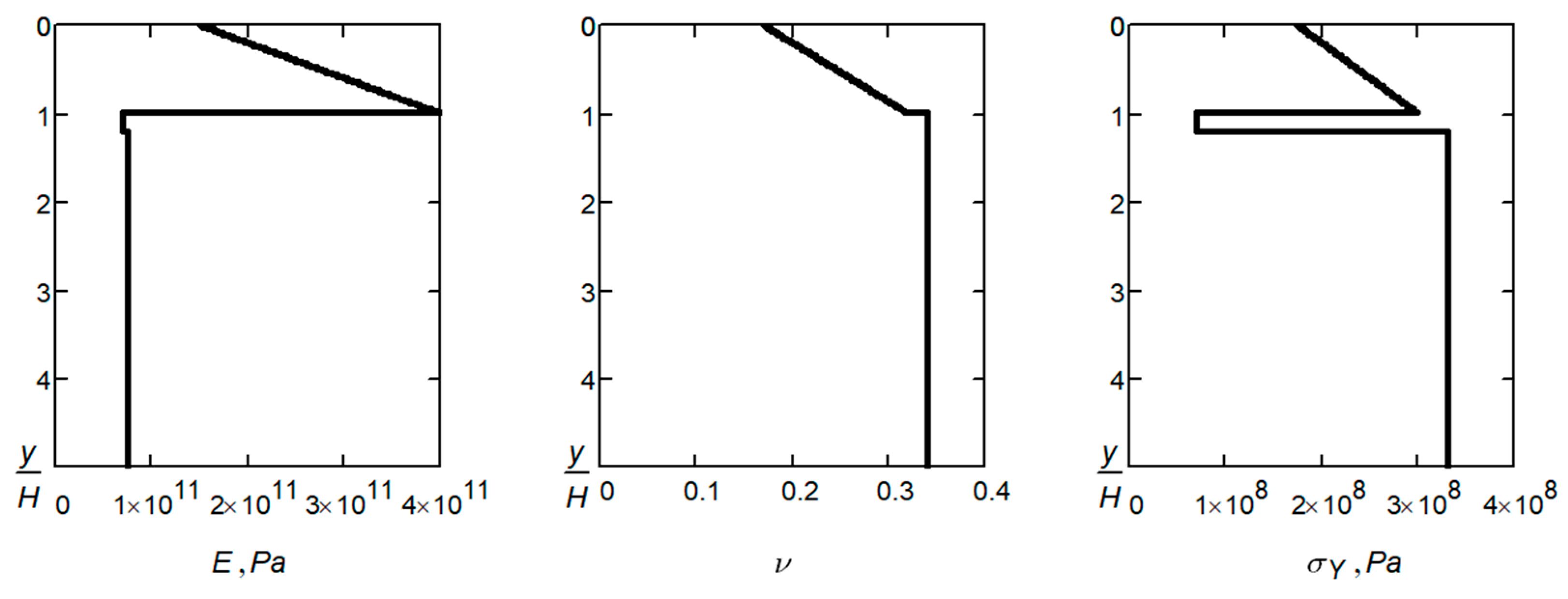
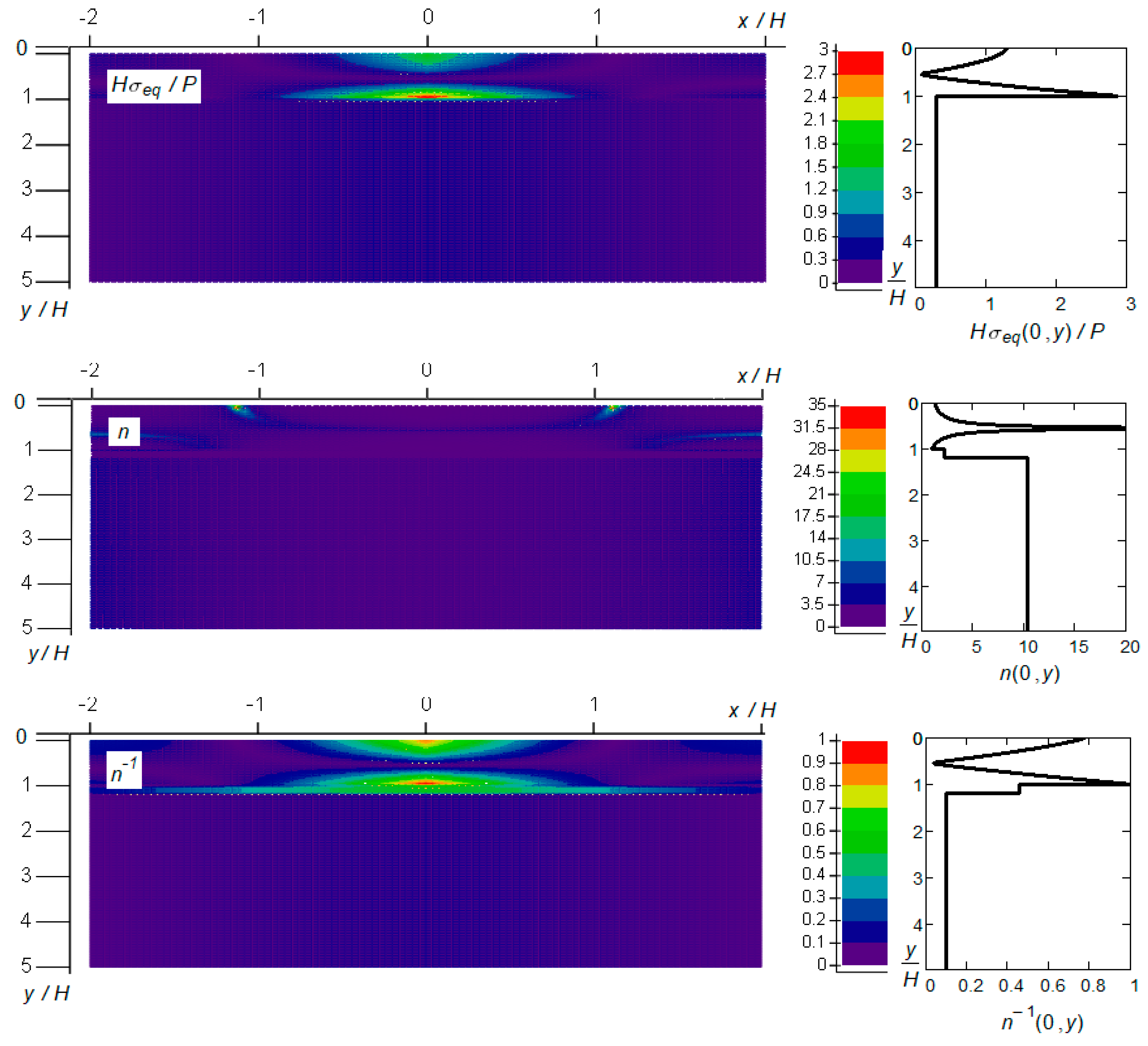
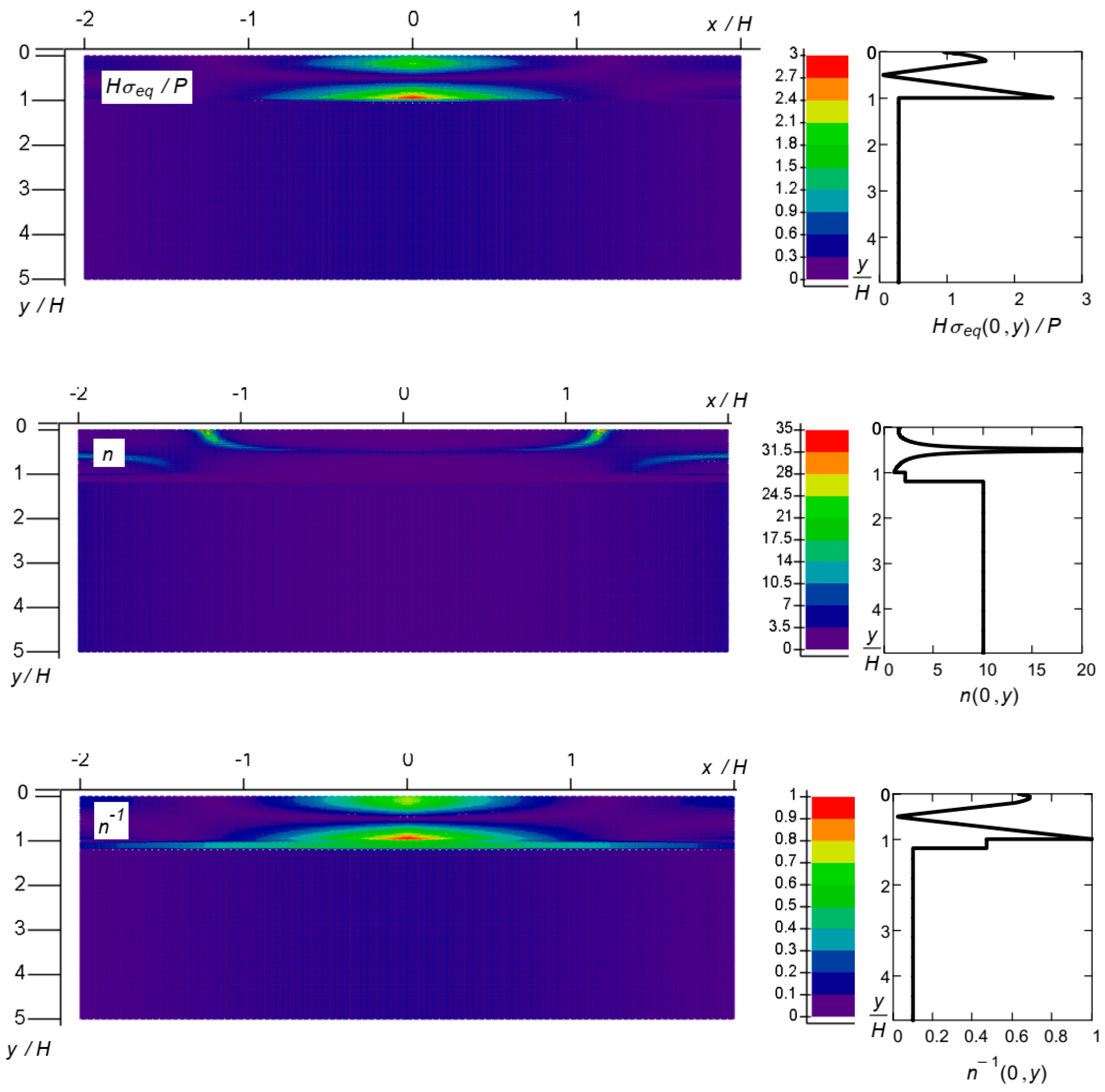
Let us now consider the case of local loading of the ceramic layer obtained by plasma electrolytic oxidation of the compact aluminum alloy D16T. A thin layer of annealed aluminum appears under the oxide layer in the alloy, so the substrate is also heterogeneous. We denote μm as the thickness of the oxide layer, μm as the thickness of annealed aluminum, μm as the total thickness of the substrate. The initial data for approximations (8), (11) are given in Table 3. Figure 6 illustrates the mechanical properties of the composite structure. The results of the calculations are presented in Figure 7.
As in the previous example, the peak of the equivalent stress is observed on the lower face of the oxide coating. Here, we have the minimum value of the safety factor. Thus, the composition will be destroyed by the cracking of the oxide layer.
Now, let us change the composition of the coating, considering the FG/ceramic coating option. The parameters for approximations (9), (11) are presented in Table 4. The graphs in Figure 8 describe the mechanical properties of the coating and substrate. The simulation results are shown in Figure 9.
An increase in the proportion of high-quality ceramics in the oxide coating grown on the D16T alloy leads to a decrease in the equivalent stresses and, therefore, to an increase in the value of the permissible local load. The type of structural integrity violation does not change: the destruction begins by cracking the lower face of the oxide coating.
4. Conclusions
The developed calculation method allows the analytical monitoring of the influence of the gradient of the mechanical characteristics of the composite coating on its stress state and ultimate equilibrium under local load. We emphasize that the method is suitable for analyzing the mechanics of an FGM coating, which can be conventionally divided into two zones: the outer, relatively rigid zone and the inner, relatively compliant one.
It was established that the limit state of a non-uniform coating is reached at the place of the minimum of the safety factor, which does not always coincide with the location of the maximum of the equivalent stress.
It is shown that a ceramic coating grown on aluminum sprayed on a steel base exhausts its load-bearing capacity due to the destruction of the substrate. The coating formed by PEO of the D16T alloy cracks due to bending on a compliant substrate.
An increase in the proportion of high-quality ceramics in oxide coatings leads to a decrease in equivalent stresses and, therefore, to an increase in the value of the permissible local load. The type of violation of structural integrity and the distribution of the safety factor in the dangerous area practically do not change.
The authors see further steps of scientific research in the transition from calculation based on the concept of allowable stresses to calculation based on the limit state.
Author Contributions
Conceptualization, I.S. and L.R.; methodology, I.S. and M.M.; software, M.M.; validation, I.S., M.M., L.R. and A.V.; formal analysis, A.V.; investigation, I.S.; resources, M.M. and A.V.; data curation, L.R.; writing—original draft preparation, I.S. and M.M.; writing—review and editing, L.R. and A.V.; visualization, I.S. and M.M.; supervision, L.R.; project administration, I.S. and M.M.; funding acquisition, A.V. All authors have read and agreed to the published version of the manuscript.
Funding
This research received no targeted external funding.
Data Availability Statement
The data are contained within this article.
Acknowledgments
The authors are grateful to the Ministry of Science and Education of Ukraine for the grants to implement the projects 0122U002082 and 0123U101858.
Conflicts of Interest
The authors declare no conflict of interest.
References
- Fayomi, O.S.; Akande, I.G.; Okokpujie, I.P.; Fakehinde, O.B.; Abioye, A.A. Composite Coating and its Industrial Applications: The Impact and Trends. Procedia Manuf. 2019, 35, 1013–1017. [Google Scholar] [CrossRef]
- Ramírez, C.; Belmonte, M.; Miranzo, P.; Osendi, M.I. Applications of Ceramic/Graphene Composites and Hybrids. Materials 2021, 14, 2071. [Google Scholar] [CrossRef] [PubMed]
- Dutkiewicz, M.; Dalyak, T.; Shatskyi, I.; Venhrynyuk, T.; Velychkovych, A. Stress Analysis in Damaged Pipeline with Composite Coating. Appl. Sci. 2021, 11, 10676. [Google Scholar] [CrossRef]
- Devarajan, D.K.; Rangasamy, B.; Amirtharaj Mosas, K.K. State-of-the-Art Developments in Advanced Hard Ceramic Coatings Using PVD Techniques for High-Temperature Tribological Applications. Ceramics 2023, 6, 301–329. [Google Scholar] [CrossRef]
- Rajiv, A.; Natalia, S.; Mrityunjay, S. Wettability and interfacial phenomena in the liquid-phase bonding of refractory diboride ceramics: Recent developments. Int. J. Appl. Ceram. Technol. 2022, 19, 1029–1049. [Google Scholar] [CrossRef]
- Semmler, C.; Gyoktepeliler-Akin, E.; Killinger, A. Plasma sprayed ceramic coatings for the thermal protection of carbon fiber reinforced plastics (CFRP): Thermal and mechanical properties of YSZ, aluminum titanate, cordierite and mullite coatings. Surf. Coat. Technol. 2023, 462, 129509. [Google Scholar] [CrossRef]
- Ropyak, L.; Shihab, T.; Velychkovych, A.; Bilinskyi, V.; Malinin, V.; Romaniv, M. Optimization of Plasma Electrolytic Oxidation Technological Parameters of Deformed Aluminum Alloy D16T in Flowing Electrolyte. Ceramics 2023, 6, 146–167. [Google Scholar] [CrossRef]
- Umashanker, L.; Bharathesh, T.P.; Roopashree, C.; Saravanan, R. A review on ceramic coatings for low carbon steel methods materials and applications. IOP Conf. Ser. Mater. Sci. Eng. 2021, 1189, 012015. [Google Scholar] [CrossRef]
- Aimovi-Pavlovi, Z.; Prsti, A.; Andri, L.; Miloevi, V.; Milievi, S. Ceramic Coating for Cast House Application; InTech: Rijeka, Croatia, 2012; pp. 261–286. [Google Scholar] [CrossRef]
- Liutyi, R.; Petryk, I.; Mogylatenko, V.; Popovych, V.; Shatska, H. Research Thermal Fields in the Crystallization Process of Steel Cast Parts. Adv. Mater. Sci. Eng. 2022, 2022, 7331866. [Google Scholar] [CrossRef]
- Paione, C.M.; Baino, F. Non-Oxide Ceramics for Bone Implant Application: State-of-the-Art Overview with an Emphasis on the Acetabular Cup of Hip Joint Prosthesis. Ceramics 2023, 6, 994–1016. [Google Scholar] [CrossRef]
- Sartori, M.; Maglio, M.; Tschon, M.; Nicoli Aldini, N.; Visani, A.; Fini, M. Functionalization of Ceramic Coatings for Enhancing Integration in Osteoporotic Bone: A Systematic Review. Coatings 2019, 9, 312. [Google Scholar] [CrossRef]
- Guillon, O. Ceramic materials for energy conversion and storage: A perspective. Int. J. Ceram. Eng. Sci. 2021, 3, 100–104. [Google Scholar] [CrossRef]
- Pal, S.; Taurino, A.; Catalano, M.; Licciulli, A. Block Copolymer and Cellulose Templated Mesoporous TiO2-SiO2 Nanocomposite as Superior Photocatalyst. Catalysts 2022, 12, 770. [Google Scholar] [CrossRef]
- Li, L.; Reynaud, P.; Fantozzi, G. Cyclic-Dependent Damage Evolution in Self-Healing Woven SiC/[Si-B-C] Ceramic-Matrix Composites at Elevated Temperatures. Materials 2020, 13, 1478. [Google Scholar] [CrossRef] [PubMed]
- Fang, G.; Gao, X.; Song, Y. A Review on Ceramic Matrix Composites and Environmental Barrier Coatings for Aero-Engine: Material Development and Failure Analysis. Coatings 2023, 13, 357. [Google Scholar] [CrossRef]
- Mehboob, G.; Liu, M.-J.; Xu, T.; Hussain, S.; Mehboob, G.; Tahir, A. A review on failure mechanism of thermal barrier coatings and strategies to extend their lifetime. Ceram. Int. 2020, 46, 8497–8521. [Google Scholar] [CrossRef]
- Bembenek, M.; Mandziy, T.; Ivasenko, I.; Berehulyak, O.; Vorobel, R.; Slobodyan, Z.; Ropyak, L. Multiclass Level-Set Segmentation of Rust and Coating Damages in Images of Metal Structures. Sensors 2022, 22, 7600. [Google Scholar] [CrossRef]
- Sathish, M.; Radhika, N.; Saleh, B. A critical review on functionally graded coatings: Methods, properties, and challenges. Compos. Part B Eng. 2021, 225, 109278. [Google Scholar] [CrossRef]
- Duryahina, Z.A.; Kovbasyuk, T.M.; Bespalov, S.A.; Pidkova, V.Y. Micromechanical and Electrophysical Properties of Al2O3 Nanostructured Dielectric Coatings on Plane Heating Elements. Mater. Sci. 2016, 52, 50–55. [Google Scholar] [CrossRef]
- Petrova, V.; Schmauder, S.; Georgiadis, A. Thermal Fracture of Functionally Graded Coatings with Systems of Cracks: Application of a Model Based on the Rule of Mixtures. Ceramics 2023, 6, 255–264. [Google Scholar] [CrossRef]
- Han, D.; Fan, H.; Yan, C.; Wang, T.; Yang, Y.; Ali, S.; Wang, G. Heat Conduction and Cracking of Functionally Graded Materials Using an FDEM-Based Thermo-Mechanical Coupling Model. Appl. Sci. 2022, 12, 12279. [Google Scholar] [CrossRef]
- Bhandari, M.; Purohit, K. Dynamic fracture analysis of functionally graded material structures—A critical review. Compos. Part C Open Access 2022, 7, 100227. [Google Scholar] [CrossRef]
- Nakajima, R.; Katori, H.; Ito, K.; Arai, M.; Suidzu, T. Numerical simulation on internal stress evolution based on formation of thermally grown oxide in thermal barrier coatings. Eng. Res. Express 2020, 2, 025037. [Google Scholar] [CrossRef]
- Tian, C.; Duan, P. Finite Element Analysis of the Nanomechanics of Hard Coatings on a Soft Polymer Substrate by a Spherical Indenter. Adv. Polym. Technol. 2020, 2020, 6903196. [Google Scholar] [CrossRef]
- Baldissera, P.; Delprete, C. Finite Element Thermo-Structural Methodology for Investigating Diesel Engine Pistons with Thermal Barrier Coating. SAE Int. J. Engines 2019, 12, 69–78. [Google Scholar] [CrossRef]
- Beake, B.D. Nano- and Micro-Scale Impact Testing of Hard Coatings: A Review. Coatings 2022, 12, 793. [Google Scholar] [CrossRef]
- Skordaris, G.; Bouzakis, K.; Charalampous, P. A critical review of FEM models to simulate the nano-impact test on PVD coatings. MATEC Web Conf. 2018, 188, 04017. [Google Scholar] [CrossRef]
- Luo, Y.; Ning, C.; Dong, Y.; Xiao, C.; Wang, X.; Peng, H.; Cai, Z. Impact Abrasive Wear Resistance of CrN and CrAlN Coatings. Coatings 2022, 12, 427. [Google Scholar] [CrossRef]
- Prysyazhnyuk, P.; Ivanov, O.; Matvienkiv, O.; Marynenko, S.; Korol, O.; Koval, I. Impact and abrasion wear resistance of the hardfacings based on high-manganese steel reinforced with multicomponent carbides of Ti-Nb-Mo-V-C system. Procedia Struct. Integr. 2022, 36, 130–136. [Google Scholar] [CrossRef]
- Tkadletz, M.; Schalk, N.; Daniel, R.; Keckes, J.; Czettl, C.; Mitterer, C. Advanced characterization methods for wear resistant hard coatings: A review on recent progress. Surf. Coat. Technol. 2016, 285, 31–46. [Google Scholar] [CrossRef]
- Shatskii, I.P. Tension of a plate containing a rectilinear cut with hinged rims. J. Appl. Mech. Tech. Phys. 1989, 30, 828–830. [Google Scholar] [CrossRef]
- Shatskii, I.P. The interaction of collinear cuts with hinged rims in a plate under tension. J. Sov. Math. 1993, 67, 3355–3358. [Google Scholar] [CrossRef]
- Shatskii, I.P. A periodic system of parallel slits with contacting edges in a distended plate. J. Math. Sci. 1995, 76, 2370–2373. [Google Scholar] [CrossRef]
- Mohammadi, S.; Yousefi, M.; Khazaei, M. A review on composite patch repairs and the most important parameters affecting its efficiency and durability. J. Reinf. Plast. Compos. 2020, 40, 3–15. [Google Scholar] [CrossRef]
- Shatskyi, I.P.; Makoviichuk, M.V.; Shcherbii, A.B. Equilibrium of Cracked Shell with Flexible Coating. In Shell Structures: Theory and Applications; CRC Press: Leiden, The Netherlands, 2018; Volume 4, pp. 165–168. [Google Scholar]
- Shatskyi, I.P.; Makoviichuk, M.V.; Shcherbii, A.B. Influence of flexible coating on the limit equilibrium of a spherical shell with meridional crack. Mater. Sci. 2020, 55, 484–491. [Google Scholar] [CrossRef]
- Nassar, M.; Mohamed, S.; Matbuly, M.; Bichir, S. Analytical Solution Of Cracked Shell Resting On Elastic Foundation. Acta Mech. Solida Sin. 1996, 9, 306–319. [Google Scholar]
- Shats’kyi, I.P.; Makoviichuk, M.V. Contact interaction of the crack edges in the case of bending of a plate with elastic support. Mater. Sci. 2003, 39, 371–376. [Google Scholar] [CrossRef]
- Sylovanyuk, V.P.; Yukhim, R.Y. Material strengthening by crack and cavity healing. Strength Mater. 2011, 43, 33–41. [Google Scholar] [CrossRef]
- Shatskyi, I.; Kurtash, I. Strength of plate with the filled crack under multiparameter loading. Procedia Struct. Integr. 2018, 13, 1482–1487. [Google Scholar] [CrossRef]
- Panasyuk, V.V.; Sylovanyuk, V.P.; Marukha, V.I. Injection Technologies for the Repair of Damaged Concrete Structures; Springer: Dordrecht, The Netherlands, 2014. [Google Scholar] [CrossRef]
- Shats’kyi, I.P. Limiting equilibrium of a plate with partially healed crack. Mater. Sci. 2015, 51, 322–330. [Google Scholar] [CrossRef]
- Kulchytsky-Zhyhailo, R.; Bajkowski, A.S. Three-dimensional analytical elasticity solution for loaded functionally graded coated half-space. Mech. Res. Commun. 2015, 65, 43–50. [Google Scholar] [CrossRef]
- Yilmaz, K.B.; Çömez, I.; Güler, M.A.; Yildirim, B. Sliding frictional contact analysis of a monoclinic coating/isotropic substrate system. Mech. Mater. 2019, 137, 103132. [Google Scholar] [CrossRef]
- Balci, M.N.; Dag, S. Dynamic frictional contact problems involving elastic coatings. Tribol. Int. 2018, 124, 70–92. [Google Scholar] [CrossRef]
- Jahedi, R.; Adibnazari, S.; Farrahi, G.H. Performance Analysis of Functionally Graded Coatings in Contact with Cylindrical Rollers. Adv. Mech. Eng. 2015, 7, 456848. [Google Scholar] [CrossRef]
- Liu, T.-J. Axisymmetric Indentation Response of Functionally Graded Material Coating; IntechOpen: London, UK, 2020. [Google Scholar] [CrossRef]
- Simchen, F.; Sieber, M.; Kopp, A.; Lampke, T. Introduction to Plasma Electrolytic Oxidation—An Overview of the Process and Applications. Coatings 2020, 10, 628. [Google Scholar] [CrossRef]
- Student, M.M.; Ivasenko, I.B.; Posuvailo, V.M.; Veselivs’ka, H.H.; Pokhmurs’kyi, A.Y.; Sirak, Y.Y.; Yus’kiv, V.M. Influence of the Porosity of a Plasma-Electrolytic Coating on the Corrosion Resistance of D16 Alloy. Mater. Sci. 2019, 54, 899–906. [Google Scholar] [CrossRef]
- Ivasenko, I.; Posuvailo, V.; Veselivska, H.; Vynar, V. Porosity Segmentation and Analysis of Oxide Ceramic Coatings of D16T Alloy. In Proceedings of the 2020 IEEE 15th International Conference on Computer Sciences and Information Technologies (CSIT), Zbarazh, Ukraine, 23–26 September 2020; Volume 2, pp. 50–53. [Google Scholar] [CrossRef]
- Sikdar, S.; Menezes, P.V.; Maccione, R.; Jacob, T.; Menezes, P.L. Plasma Electrolytic Oxidation (PEO) Process–Processing, Properties, and Applications. Nanomaterials 2021, 11, 1375. [Google Scholar] [CrossRef]
- Ragalevičius, R.; Stalnionis, G.; Niaura, G.; Jagminas, A. Micro-Arc oxidation of Ti in a solution of sulfuric acid and Ti+3 salt. Appl. Surf. Sci. 2008, 254, 1608–1613. [Google Scholar] [CrossRef]
- Hartjen, P.; Hoffmann, A.; Henningsen, A.; Barbeck, M.; Kopp, A.; Kluwe, L.; Precht, C.; Quatela, O.; Gaudin, R.; Heiland, M.; et al. Plasma Electrolytic Oxidation of Titanium Implant Surfaces: Microgroove-Structures Improve Cellular Adhesion and Viability. Vivo 2018, 32, 241–247. [Google Scholar] [CrossRef]
- Pokhmurskii, V.; Nykyforchyn, H.; Student, M.; Klapkiv, M.; Pokhmurska, H.; Wielage, B.; Grund, T.; Wank, A. Plasma electrolytic oxidation of arc-sprayed aluminum coatings. J. Therm. Spray Technol. 2007, 16, 998–1004. [Google Scholar] [CrossRef]
- Posuvailo, V.M.; Klapkiv, M.D.; Student, M.M.; Sirak, Y.Y.; Pokhmurska, H.V. Gibbs energy calculation of electrolytic plasma channel with inclusions of copper and copper oxide with Al-base. IOP Conf. Ser. Mater. Sci. Eng. 2017, 181, 012045. [Google Scholar] [CrossRef]
- Tokovyy, Y.; Ma, C.-C. The Direct Integration Method for Elastic Analysis of Nonhomogeneous Solids; Cambridge Scholars Publishing: Newcastle, UK, 2021; p. 342. ISBN 10-1-5275-6149-6. [Google Scholar]
- Tokovyy, Y.V. Solutions of Axisymmetric Problems of Elasticity and Thermoelasticity for an Inhomogeneous Space and a Half Space. J. Math. Sci. 2019, 240, 86–97. [Google Scholar] [CrossRef]
- Tokovyy, Y.; Chyzh, A.; Ma, C.C. An analytical solution to the axisymmetric thermoelasticity problem for a cylinder with arbitrarily varying thermomechanical properties. Acta Mech. 2019, 230, 1469–1485. [Google Scholar] [CrossRef]
- Shatskyi, I.P.; Ropyak, L.Y.; Makoviichuk, M.V. Strength optimization of a two-layer coating for the particular local loading conditions. Strength Mater. 2016, 48, 726–730. [Google Scholar] [CrossRef]
- Ropyak, L.Y.; Shatskyi, I.P.; Makoviichuk, M.V. Analysis of interaction of thin coating with an abrasive using one-dimensional model. Metallofiz. Noveishie Tekhnol. 2019, 41, 647–654. [Google Scholar] [CrossRef]
- Reddy, J.N. Mechanics of Laminated Composite Plates and Shells: Theory and Analysis, 2nd ed.; CRC Press: Boca Raton, FL, USA, 2003. [Google Scholar] [CrossRef]
Figure 1.
Scheme of the task.

Figure 2.
Distribution of mechanical characteristics of the FG coating grown by oxidation of sprayed aluminum.
Figure 2.
Distribution of mechanical characteristics of the FG coating grown by oxidation of sprayed aluminum.

Figure 3.
Distribution of equivalent stress, safety factor and normalized equivalent stress in the FG coating formed by oxidation of sprayed aluminum.
Figure 3.
Distribution of equivalent stress, safety factor and normalized equivalent stress in the FG coating formed by oxidation of sprayed aluminum.


Figure 4.
Distribution of mechanical characteristics of the FG/ceramic coating grown by oxidation of sprayed aluminum.
Figure 4.
Distribution of mechanical characteristics of the FG/ceramic coating grown by oxidation of sprayed aluminum.

Figure 5.
Distribution of equivalent stresses, safety factor and normalized equivalent stresses in the FG/ceramic coating formed by oxidation of sprayed aluminum.
Figure 5.
Distribution of equivalent stresses, safety factor and normalized equivalent stresses in the FG/ceramic coating formed by oxidation of sprayed aluminum.

Figure 6.
Distribution of mechanical characteristics of the FG coating grown by oxidation of compact alloy D16T.
Figure 6.
Distribution of mechanical characteristics of the FG coating grown by oxidation of compact alloy D16T.

Figure 7.
Distribution of equivalent stress, safety factor and normalized equivalent stress in the FG coating formed by oxidation of the D16T alloy.
Figure 7.
Distribution of equivalent stress, safety factor and normalized equivalent stress in the FG coating formed by oxidation of the D16T alloy.

Figure 8.
Distribution of mechanical characteristics of the FG/ceramic coating grown by oxidation of compact alloy D16T.
Figure 8.
Distribution of mechanical characteristics of the FG/ceramic coating grown by oxidation of compact alloy D16T.

Figure 9.
Distribution of equivalent stresses, safety factor and normalized equivalent stresses in the FG/ceramic coating formed by oxidation of the D16T alloy.
Figure 9.
Distribution of equivalent stresses, safety factor and normalized equivalent stresses in the FG/ceramic coating formed by oxidation of the D16T alloy.


Table 1.
Mechanical properties of the FG coating grown by oxidation of sprayed aluminum.
| Material | Layer Boundary Coordinate y, μm | , GPa | , MPa | |
|---|---|---|---|---|
| Al2O3 | 0 | 150 | 0.17 | 175 |
| 250 – 0 | 400 | 0.32 | 300 | |
| Al | 250 + 0 | 75 | 0.34 | 67 |
| 300 | 75 | 0.34 | 67 |
Table 2.
Mechanical properties of the FG/ceramic coating grown by oxidation of sprayed aluminum.
| Material | Layer Boundary Coordinate y, μm | E, GPa | ν | σY, MPa |
|---|---|---|---|---|
| Al2O3 | 0 | 150 | 0.17 | 175 |
| 50 | 400 | 0.32 | 300 | |
| 250 − 0 | 400 | 0.32 | 300 | |
| Al | 250 + 0 | 75 | 0.34 | 67 |
| 300 | 75 | 0.34 | 67 |
Table 3.
Mechanical properties of the coating FG grown by oxidation of a compact alloy D16T.
| Material | Layer Boundary Coordinate y, μm | , GPa | , MPa | |
|---|---|---|---|---|
| Al2O3 | 0 | 150 | 0.17 | 175 |
| 250 − 0 | 400 | 0.32 | 300 | |
| Al | 250 + 0 | 70 | 0.34 | 70 |
| 300 – 0 | 70 | 0.34 | 70 | |
| D16T | 300 + 0 | 75 | 0.34 | 330 |
| 1250 | 75 | 0.34 | 330 |
Table 4.
Mechanical properties of the FG/ceramic coating grown by oxidation of a compact alloy D16T.
Table 4.
Mechanical properties of the FG/ceramic coating grown by oxidation of a compact alloy D16T.
| Material | Layer Boundary Coordinate y, μm | E, GPa | σY, MPa | |
|---|---|---|---|---|
| Al2O3 | 0 | 150 | 0.17 | 175 |
| 50 | 400 | 0.32 | 300 | |
| 250 − 0 | 400 | 0.32 | 300 | |
| Al | 250 + 0 | 70 | 0.34 | 70 |
| 300 – 0 | 70 | 0.34 | 70 | |
| D16T | 300 + 0 | 75 | 0.34 | 330 |
| 1250 | 75 | 0.34 | 330 |
Disclaimer/Publisher’s Note: The statements, opinions and data contained in all publications are solely those of the individual author(s) and contributor(s) and not of MDPI and/or the editor(s). MDPI and/or the editor(s) disclaim responsibility for any injury to people or property resulting from any ideas, methods, instructions or products referred to in the content. |
© 2023 by the authors. Licensee MDPI, Basel, Switzerland. This article is an open access article distributed under the terms and conditions of the Creative Commons Attribution (CC BY) license (https://creativecommons.org/licenses/by/4.0/).
Share and Cite
MDPI and ACS Style
Shatskyi, I.; Makoviichuk, M.; Ropyak, L.; Velychkovych, A. Analytical Model of Deformation of a Functionally Graded Ceramic Coating under Local Load. Ceramics 2023, 6, 1879-1893. https://doi.org/10.3390/ceramics6030115
AMA Style
Shatskyi I, Makoviichuk M, Ropyak L, Velychkovych A. Analytical Model of Deformation of a Functionally Graded Ceramic Coating under Local Load. Ceramics. 2023; 6(3):1879-1893. https://doi.org/10.3390/ceramics6030115
Chicago/Turabian StyleShatskyi, Ivan, Mykola Makoviichuk, Liubomyr Ropyak, and Andrii Velychkovych. 2023. "Analytical Model of Deformation of a Functionally Graded Ceramic Coating under Local Load" Ceramics 6, no. 3: 1879-1893. https://doi.org/10.3390/ceramics6030115