Article

Boosted Catalytic Performance of Ni2Co2@T-PMo@ZIF-67 for Glucose Oxidation in a Direct-Glucose Fuel Cell

1
School of Environmental Science and Engineering, Tianjin University, Tianjin 300354, China
2
College of Food Science and Engineering, Tianjin Agricultural University, Tianjin 300384, China
*
Authors to whom correspondence should be addressed.
These authors contributed equally to this work.
Catalysts 2024, 14(1), 19; https://doi.org/10.3390/catal14010019
Submission received: 11 October 2023 / Revised: 21 December 2023 / Accepted: 24 December 2023 / Published: 27 December 2023
(This article belongs to the Special Issue New Horizons for Heterogeneous Catalysts, 2nd Edition)

Abstract

:
In this study, we report on how to design efficient catalysts for glucose oxidation via the transitional metal doping of nanohybrids of polyoxometalates (POMs) and metal-organic frameworks (MOFs). ZIF-67, a cobalt-based MOF, as well as phosphomolybdic acid (PMo), were used as precursors for the fabrication of pyrolyzed PMo@ZIF-67 (T-PMo@ZIF-67). A different amount of Ni2+ was doped into PMo@ZIF-67 to produce NixCoy@T-PMo@ZIF-67. Among them, Ni2Co2@T-PMo@ZIF-67 had the best performance. The power density of the fuel cell that used Ni2Co2@T-PMo@ZIF-67 as an anode catalyst was 3.76 times that of the cell that used active carbon as an anode catalyst. SEM and EDS mapping results indicate that Ni2Co2@T-PMo@ZIF-67 has a spherical structure and rough surface, and elements such as cobalt, nickel, and molybdenum are evenly distributed. XRD characterization indicates that Co3O4, CoMoO4, CoNiO4, and MoNiO4 co-exist in the composites. It is supposed that Co2+, Mo6+, and Ni2+ in the composites may have synergistic effects on the catalytic oxidation of glucose.

Graphical Abstract

1. Introduction

Metal-organic frameworks (MOFs) are a class of crystalline porous materials with a periodic network structure formed by interconnecting inorganic metal centers (metal ions or metal clusters) with bridging organic ligands through self-assembly. In MOFs, the organic ligands, as well as metal ions or clusters, are arranged with an obvious orientation, which can form different framework pore structures, thus exhibiting different adsorption properties, optical properties, electromagnetic properties, catalytic properties, etc. [1,2]. The preparation of MOF-derived materials performed via pyrolysis using metal-organic framework materials (MOFs) as templates, or precursors, has become a popular method for catalyst development [3,4,5,6]. The integration of MOFs into various materials, such as metal nanoparticles and semiconductors, can further improve the performance of MOF derivatives, but the selection of specific metal precursors and MOFs ligands is very limited, so the obtained functional materials do not meet the increasing needs of diverse applications [7]. Polyoxometalate (POM) is a negatively charged transition metal ion aggregate formed in a high oxygen state, and has a special and superior three-dimensional structure, as well as physical and chemical properties [8,9,10]. The structure, surface chemistry, polarity, charge, and redox properties of POMs can be easily tailored by the introduction of organic moieties and metal-organic groups. However, their electrochemical applications are limited due to their moderate electrochemical performance and low specific surface area. MOFs have the advantages of high porosity, large specific surface area, good chemical stability, and multiple adsorption sites. They can enclose POMs in their metal-organic skeleton so as to avoid the loss of POMs and prolong the catalyst service life [11,12]. Therefore, the combination of MOFs and POMs is expected to expand the availability of transition metal elements, as well as improve the performance of MOF-derived materials [13,14,15,16,17].
With the gradual depletion of fossil resources, and the aggravated environmental deterioration, the development of novel technologies for sustainable energy conversion and storage has attracted global attention [18,19,20,21]. Glucose fuel cells (GFC) are one type of fuel cells that produce electricity by oxidizing glucose at the anode and reducing oxygen at the cathode. Glucose is the most abundant monosaccharide in nature, and is cheap and easy to obtain, non-volatile, and safe. It is also environmentally friendly, green, and non-toxic [22]. Glucose fuel cells can be divided into two categories according to the operating environment: external fuel cells and implantable fuel cells. In the case of external operation, glucose fuel cells can directly use agricultural waste as an energy source for power generation, which has the advantages of simplicity, safety, environmental protection, and wide fuel sources. Implantable fuel cells use glucose in body fluids, such as interstitial fluid, tears, blood, and cerebrospinal fluid to power the corresponding implanted devices. They have broad application prospects in implantable medical devices such as cardiac pacemakers and drug delivery pumps [23,24]. Generally, glucose is harder to oxidize than conventional substrates of fuel cells such as hydrogen and methanol, and thus needs an efficient and selective catalyst [25,26]. The anodic glucose oxidation reaction is slow, and the substrate is difficult to react completely [27,28]. The catalyst can improve the anodic oxidation rate of glucose fuel cells [29,30,31,32]. Currently, Pt is considered to be the most efficient catalyst for various fuel cells, but high Pt loading are required to meet practical applications [33,34]. As a result, fuel cells are too expensive to be commercialized on a large scale. It is a great challenge to develop high performance and low-cost anode catalysts for GFCs [35].
In this paper, we used phosphomolybdic acid (PMo, a keggin-type POM), as well as ZIF-67 (a cobalt-based MOF), as precursors for the fabrication of pyrolyzed PMo@ZIF-67 (T-PMo@ZIF-67). We tried to enhance their catalytic performance by doping various transitional metal ions (Ni2+, Fe3+, Cu2+, and Zn2+) in the preparation process of T-PMo@ZIF-67. The effects of doping with different transitional metal ions on the electrochemical performance were investigated. In addition, the possible mechanism of glucose oxidation under an alkaline environment was also discussed.

2. Results and Discussion

2.1. Electrochemical Performance Characterization of Anodic Catalysts

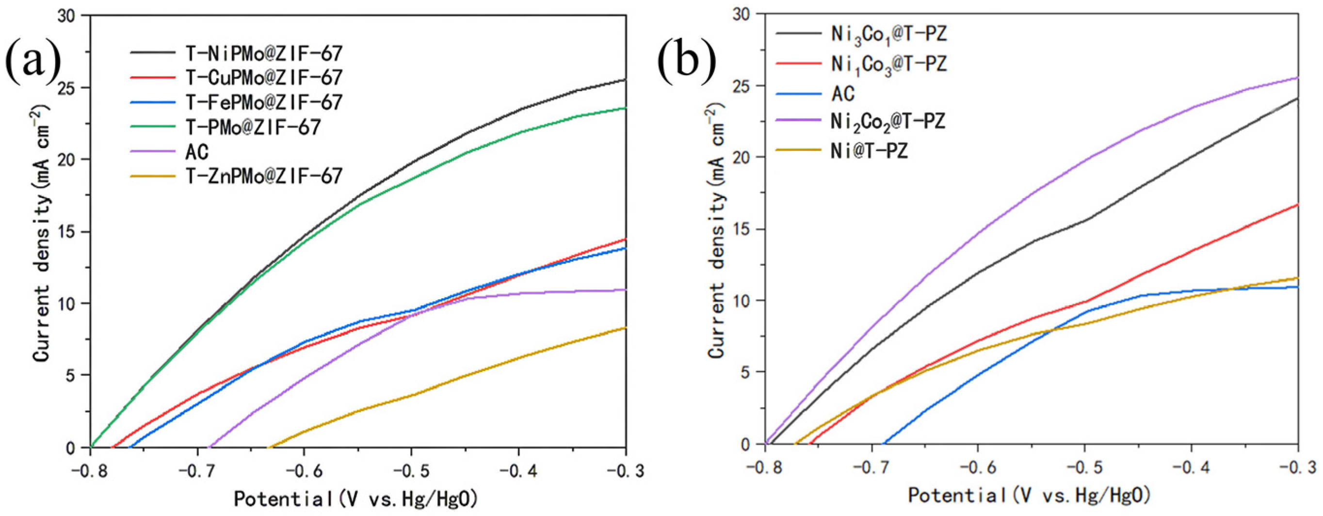
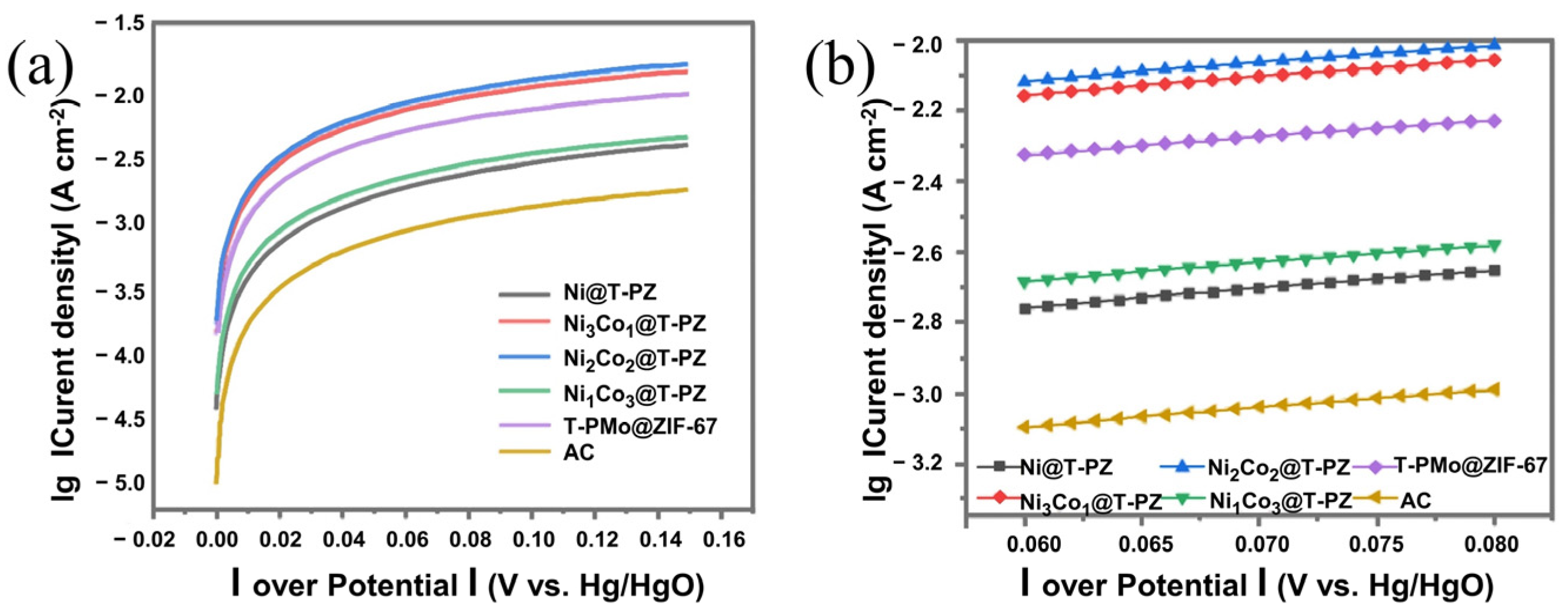
2.1.1. Linear Sweep Voltammetry (LSV) Measurement

Figure 1a shows the LSV plots of the different T-XPMo@ZIF-67 anodes, where the current density of T-NiPMo@ZIF-67 was always higher than that of T-PMo@ZIF-67. The current density of T-CuPMo@ZIF-67 and T-FePMo@ZIF-67 were lower than that of T-PMo@ZIF-67 at the same potential, and the current density of T-ZnPMo@ZIF-67 was even lower than the blank control anode (AC) at the potential range of −0.46 V~0.3 V. The oxidation current increased in the order of T-ZnPMo@ZIF-67 < AC < T-FePMo@ZIF-67 < T-CuPMo@ZIF-67 < T-PMo@ZIF-67 < T-NiPMo@ZIF-67. This indicates that Zn2+ remarkably impairs the catalytic activity of T-PMo@ZIF-67. It can be inferred that Zn2+ has a lower catalytic activity towards glucose oxidation. The addition of Zn2+ may precede the formation of ZIF-8 material by Co2+ during the preparation process, resulting in the loss of Co2+ during the preparation process and the reduction of Co2+ involved in the reaction. Although Cu2+ and Fe2+ can promote the glucose oxidation reaction, the catalytic performances of T-CuPMo@ZIF-67 and T-FePMo@ZIF-67 were not as high as that of T-PMo@ZIF-67. The doping of Ni2+ in the catalyst significantly increased the oxidation current of the glucose.
In order to optimize the catalytic performance of T-NiPMo@ZIF-67, the Co2+/Ni2+ ratio was tailored in the synthesis process of NixCoy@T-PZ. Figure 1b shows the LSV measurements of the catalysts with different Co2+/Ni2+ ratios. The current densities of the four anodes were higher than that of the AC control, and the maximum current density was increased in the order of AC < Ni@T-PZ < Ni1Co3@T-PZ < Ni3Co1@T-PZ < Ni2Co2@T-PZ. This result further confirmed that doping with appropriate amounts of Ni2+ (1.25 mM) can promote the oxidation of glucose, and the optimal Co2+/Ni2+ ratio as a molar ratio was 1:1. Co2+ and Ni2+ may have a synergistic effect on the catalytic oxidation capacity of glucose. Therefore, the LSV curves of Ni3Co1@T-PZ and Ni2Co2@T-PZ were higher than that of Ni@T-PZ, which Ni2+ was added alone. However, when the concentration of either metal ion was higher, the catalytic performance of the catalyst would deteriorate.

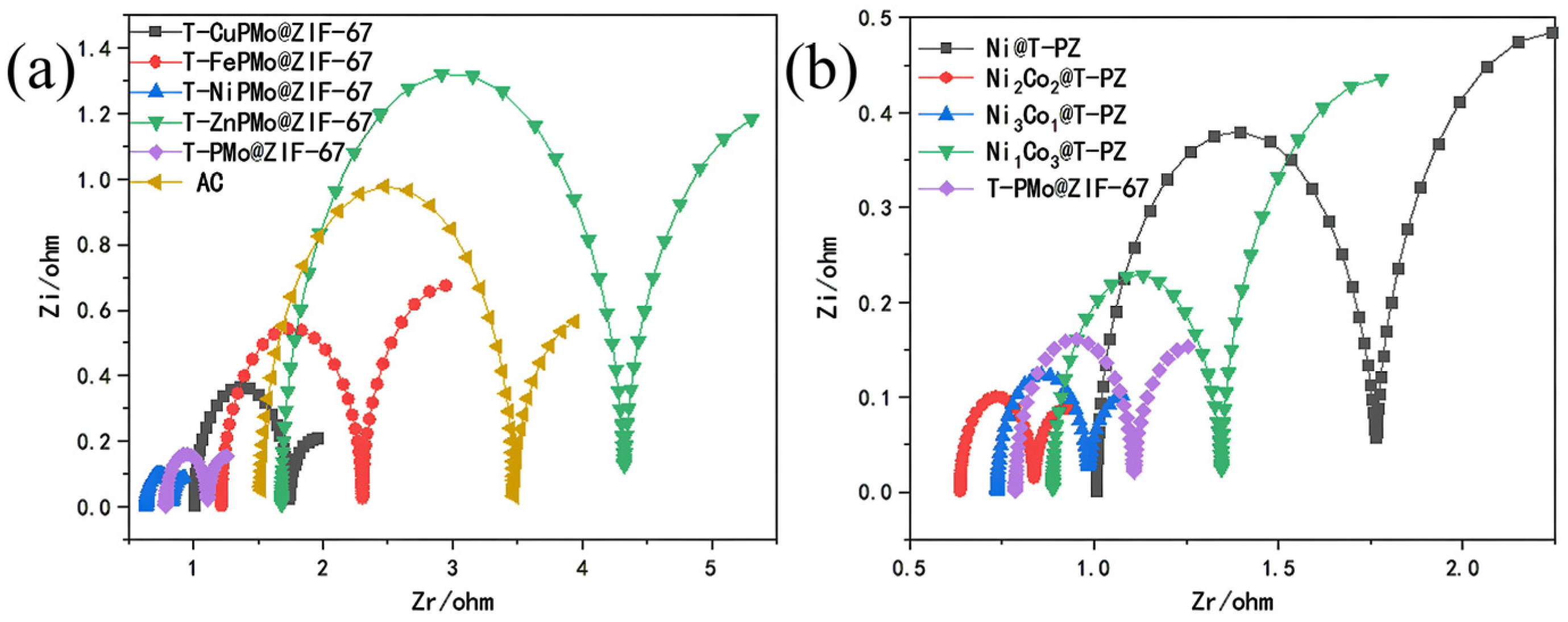
2.1.2. Electrochemical Impedance Testing (EIS) of Anodes

EIS tests were performed on anodes modified with different catalysts. The resulting data were fitted by the equivalent circuit diagram (Figure S1). Figure 2a shows the EIS curves corresponding to blank anodes (AC), T-PMo@ZIF-67, T-NiPMo@ZIF-67, T-CuPMo@ZIF-67, T-FePMo@ZIF-67, and T-ZnPMo@ZIF-67 catalyst doped anodes. Table 1 shows the impedance values of each part of the anode modified by different anode catalysts. As can be seen from the figure, the performance of T-NiPMo@ZIF-67 was significantly better than that of blank AC anode and other metal ion catalysts, showing the smallest Ohmic resistance and charge transfer resistance. The difference between the several electrodes was that the metal ions added were different, which indicates that the type of metal ions has an important effect on the conductivity of the electrode surface.
In order to better study the effects of Co2+/Ni2+ ratio on the performance of T-NiPMo@ZIF-67, the impedance of the anodes with different Co2+/Ni2+ ratios were analyzed. Figure 2b and Table 2 show the Rct was increased in the order of Ni2Co2@T-PZ < Ni3Co1@T-PZ < T-PMo@ZIF-67 < Ni1Co3@T-PZ < Ni@T-PZ. As can be seen from Table 2, changes of Rs of the anodes with different Co2+/Ni2+ ratios were consistent with Rct. Ni2Co2@T-PZ had the smallest Rs of 0.686 Ω. The Rct of Ni2Co2@T-PZ (0.1755 Ω) was decreased by 42.70% when compared with T-PMo@ZIF-67 (0.3063 Ω), and decreased by 76.85% when compared with Ni@T-PZ (0.7582 Ω). Compared with T-PMo@ZIF-67 and Ni@T-PZ, the total resistance of Ni2Co2@T-PZ decreased by 24.88% and 61.10%, respectively. These data can explain why the performance of Ni2Co2@T-PZ is better than that of other catalysts. The decrease of transfer resistance accelerated the electron transfer and improved the current flow.

2.1.3. The Tafel Curve of Anodes

The Tafel curve is a section of the strong polarization region of the general polarization curve. For the simpler electron transfer process, the Tafel curve can be used for analysis, and the exchange current density can be obtained through using the linear part of the Tafel curve to intersect the axis through the extension line, so as to calculate the number of electrons transferred in the electrochemical process. Figure 3a shows the Tafel curve of different catalyst modified anodes, and Figure 3b shows the fitting curves. Table 3 shows the fitting results of the Tafel measurement. As can be seen from Figure 3b and Table 3, The Tafel slopes of AC, T-PMo@ZIF-67, Ni@T-PZ, Ni3Co1@T-PZ, Ni2Co2@T-PZ, and Ni1Co3@T-PZ were 186.1702, 207.3794, 184.5195, 197.7402, 194.4443 and 191.6377 mV dec−1 respectively. The I0 of the different anodes were increased in the order of AC (3.831 × 10⁻⁴ A cm−2) < Ni@T-PZ (8.283 × 10⁻⁴ A cm−2) < Ni1Co3@T-PZ (10.117 × 10⁻⁴ A cm−2) < T-PMo@ZIF-67 (24.526 × 10⁻⁴ A cm−2) < Ni3Co1@T-PZ (34.901 × 10⁻⁴ A cm−2) < Ni2Co2@T-PZ (37.884 × 10⁻⁴ A cm−2). Ni2Co2@T-PZ had the highest exchange current density, which was much higher than that of the AC anode. This indicates that the glucose oxidation reaction of Ni2Co2@T-PZ catalyst doped anode can be carried out at a lower overpotential. It was confirmed that Ni2Co2@T-PZ can significantly promote the oxidation of glucose, increase the reaction rate, and improve the performance of fuel cell.

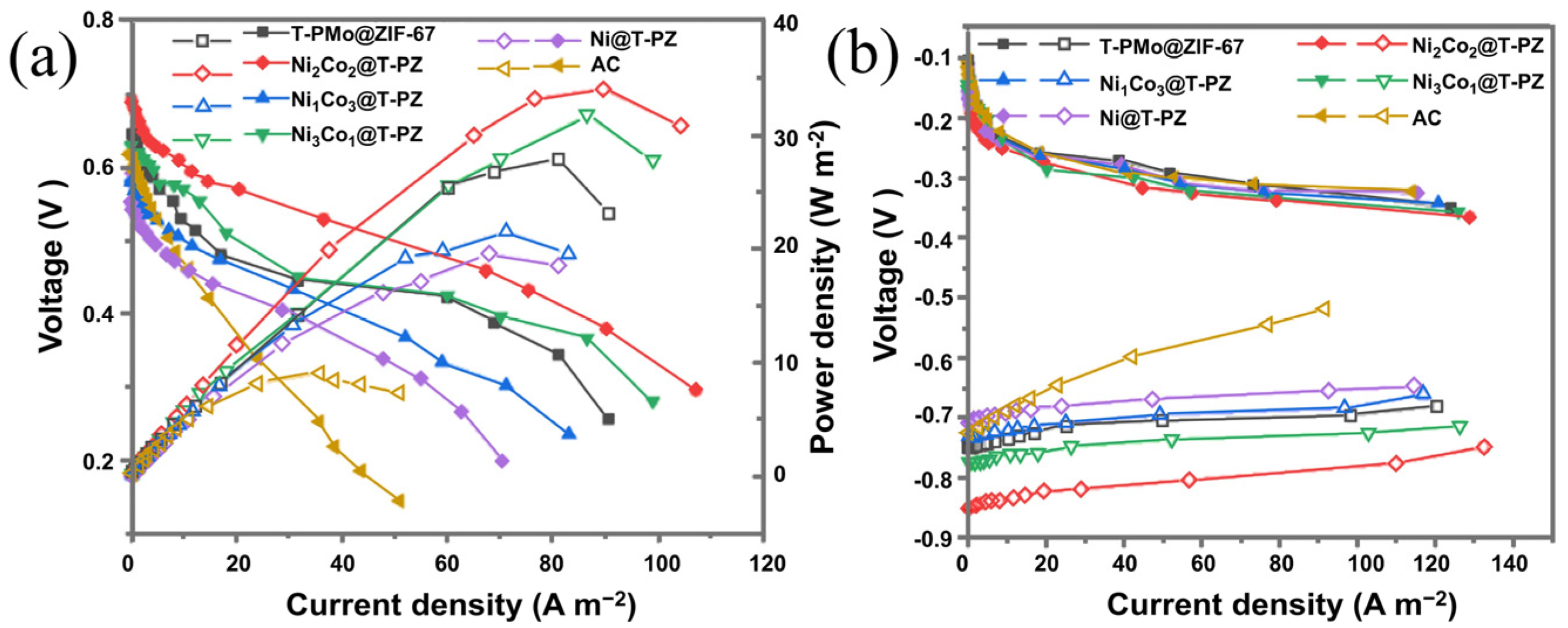
2.1.4. Power Density (PD) and Polarization Curves (PC) of Different Anodes in Fuel Cells

In order to evaluate the performance of Ni2Co2@T-PZ in real alkaline glucose fuel cells, a whole-cell investigation was conducted through using carbon fabric as the air cathode, and catalyst-modified active carbon as the anode. Figure 4a shows the power density curves of the fuel cell with the different catalyst-modified anodes. The power densities of the fuel cell had a similar change trend, rising at first and then declining. The maximum power densities of the fuel cell with different anodes increased in the order of AC (9.060 W m−2) < Ni@T-PZ (19.567 W m−2) < Ni1Co3@T-PZ (21.515 W m−2) < T-PMo@ZIF-67 (27.916 W m−2) < Ni3Co1@T-PZ (31.774 W m−2) < Ni2Co2@T-PZ (34.065 W m−2). The power density of the fuel cell with Ni2Co2@T-PZ as the anode catalyst was always higher than that of the others with the maximum power density of 34.065 W m−2, which was 1.22 times of that with T-PMo@ZIF-67 anode, 1.74 times of that with Ni@T-PZ anode, and 3.76 times of that with AC anode. Compared to other glucose fuel cells, our work has advantages in terms of performance and cost (Table 4).
Figure 4b shows the polarization curves of the different electrodes. Because all the systems use the same air cathode, the changes of total voltage and power density should be attributed to different anodes. Among the six anodes, the potential of the AC anode decreased the fastest. The potentials of Ni@T-PZ and Ni1Co3@T-PZ anodes had a mild decrease compared to that of the AC anode. Ni2Co2@T-PZ anode had the most robust performance. This result is consistent with the LSV, EIS, and Tafel measurements.

2.2. Characterization of T-PMo@ZIF-67

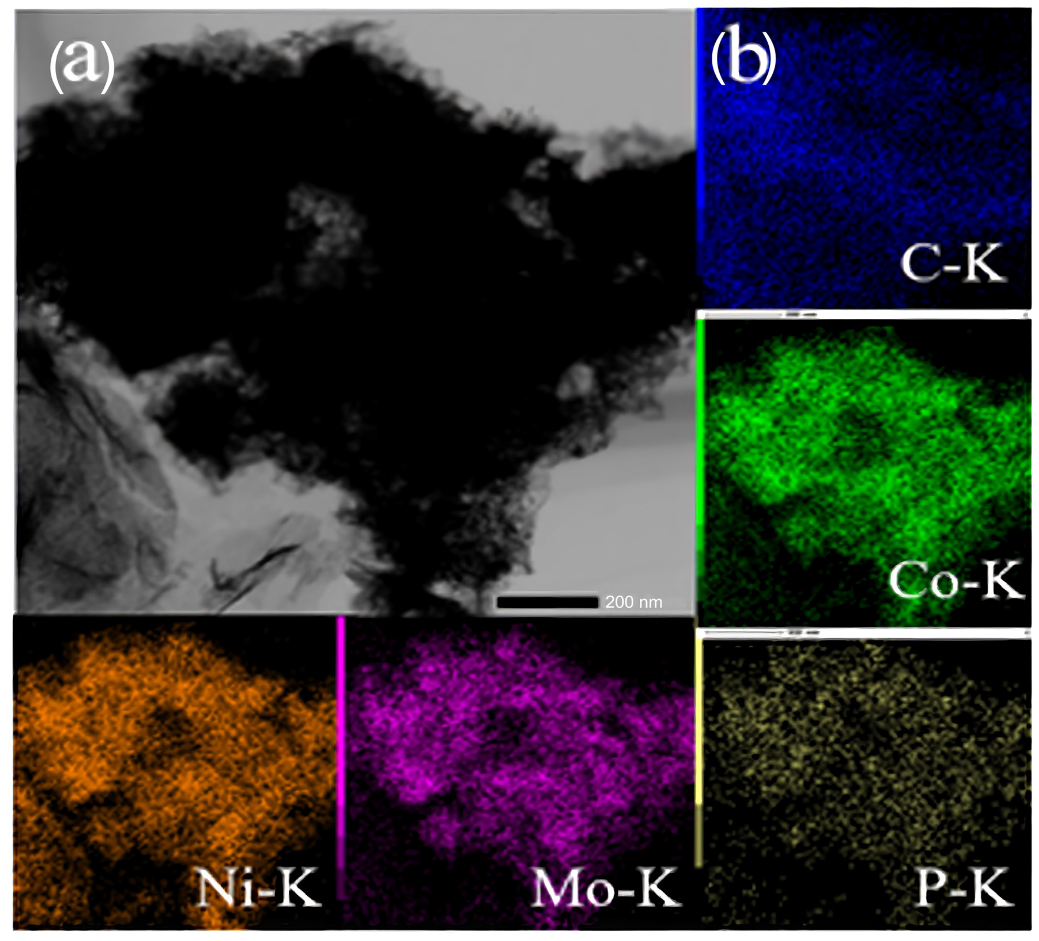
2.2.1. Scanning Electron Microscope Analysis

SEM characterization of the catalyst was used to observe the microstructure of Ni2Co2@T-PZ (Figure 5a). The diameter of Ni2Co2@T-PZ particle was about 200 nm. The element mapping for Ni2Co2@T-PZ showed that C, Co, Ni, Mo, O, and P were uniformly distributed throughout the structure, which proved the successful doping of Ni2+ in T-PMo@ZIF-67, and the distribution was uniform with no obvious agglomeration (Figure 5b). The energy dispersion spectra (EDS) of Ni2Co2@T-PZ catalyst indicated the molar ratio of Co, Mo, and Ni was 3.02:1:3.26 (Figure S2).

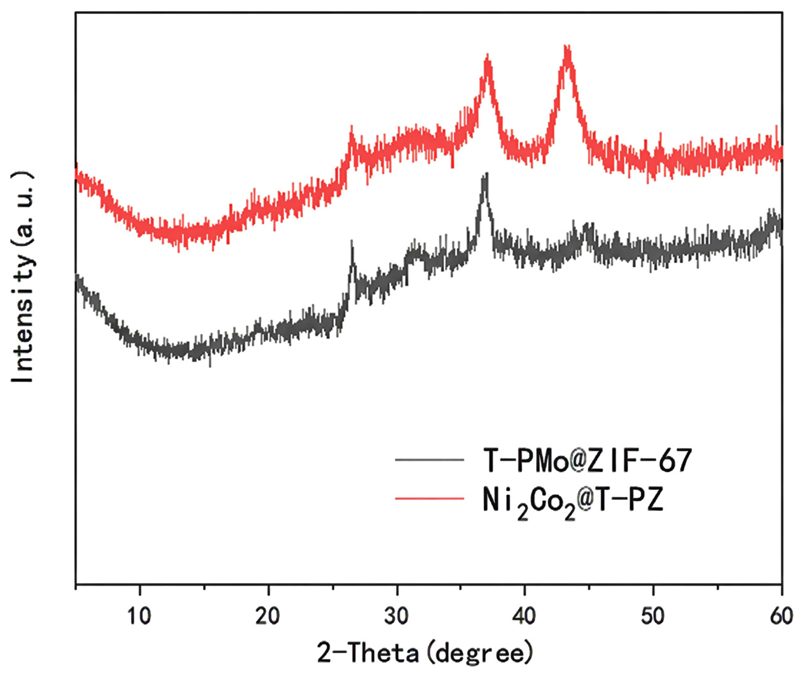
2.2.2. X-ray Diffraction Analysis

The XRD spectra of T-PMo@ZIF-67 and Ni2Co2@T-PZ (Figure 6) were compared, and the result showed that the peak size and peak area of the latter was remarkably increased, indicating a significant decrease in grain size. The presence of peaks at 36.6°, 43.3°, 45.2°, and 50.6° represents the presence of CoNiO4 and MoNiO4, which indicates that Ni2+ reacted with Co2+ and Mo2+ during the fabrication process. EDS and XRD results imply that Co3O4, CoMoO4, CoNiO4, and MoNiO4 coexist in Ni2Co2@T-PZ.

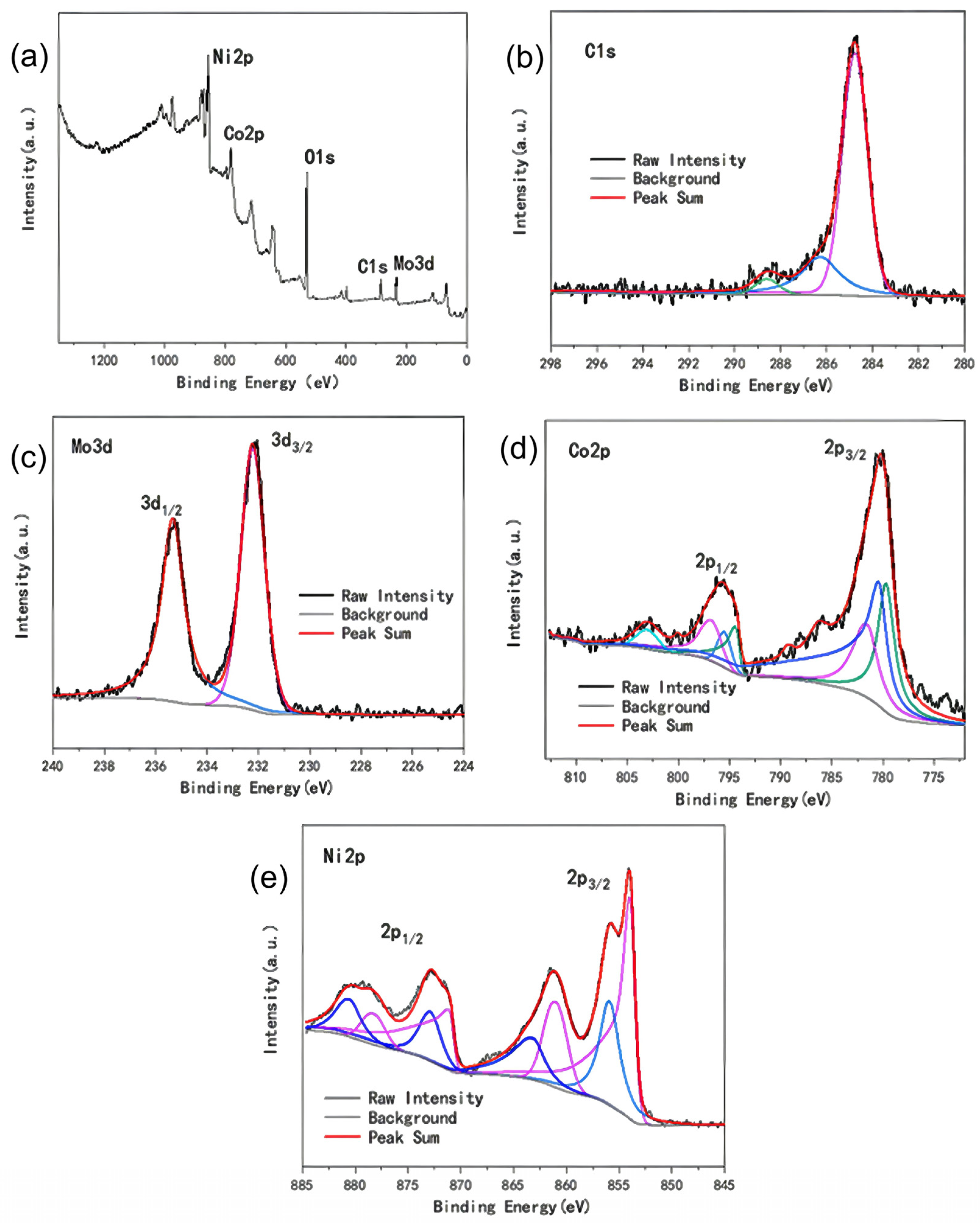
2.2.3. X-ray Photoelectron Spectroscopy Analysis

The characterization of XPS is helpful when analyzing the elemental composition and valence distribution of Ni2Co2@T-PZ, so as to better understand the underlying catalytic mechanism. Figure 7a shows the XPS spectra of each element of Ni2Co2@T-PZ. The peaks centered at 855.10 eV, 796.06 eV, 530.14 eV, 284.95 eV, and 232.49 eV were Ni2p, Co2p, O1s, C1s, and Mo3d. The peaks centered at 284.77 eV, 286.28 eV, and 288.59 eV shown in Figure 7b represent C=C/C-C, C=C/C-C, and C=O for C1s signals. In Figure 7c, it can be seen there were two splitting slits at 235.34 eV and 232.22 eV in the XPS pattern of Mo3d, and the column width was 3.12 eV, which can be ascribed to Mo6+. The spectrum of Co2p was mainly derived from the splitting of two orbitals, which were spin orbital double peaks with a column width of about 15 eV (Figure 7d). The spin orbital double peaks at 780 eV and 795 eV represented the Co2p3/2 and Co2p1/2 levels of the Co ion, respectively. The satellite peaks could be used to identify the oxidation state of Co ions. The energy gap between satellite peaks and the main peaks was 6 eV and 8 eV respectively, indicating that Co2+ and Co3+ co-exist in the sample. Figure 7e shows the XPS spectrum of Ni2p. The peaks at the binding energy of 853.97 eV and 860.98 eV was the characteristic peak of Ni3+, and the double peak at the binding energy of 855.87 eV and 863.14 eV was the characteristic peak of Ni2+. This result indicates that Ni3+ and Ni2+ coexist in the sample.

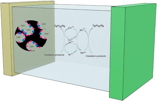
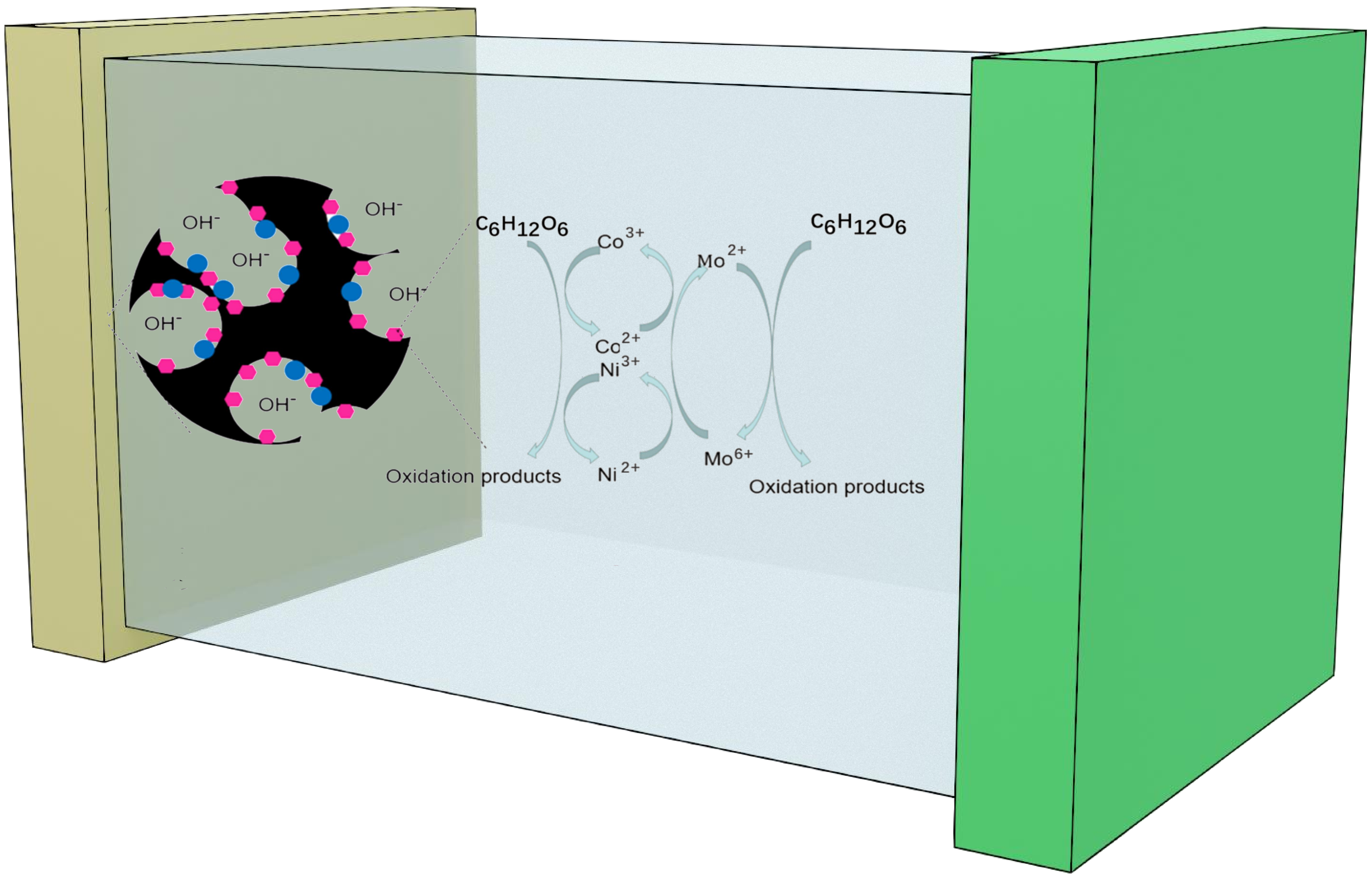
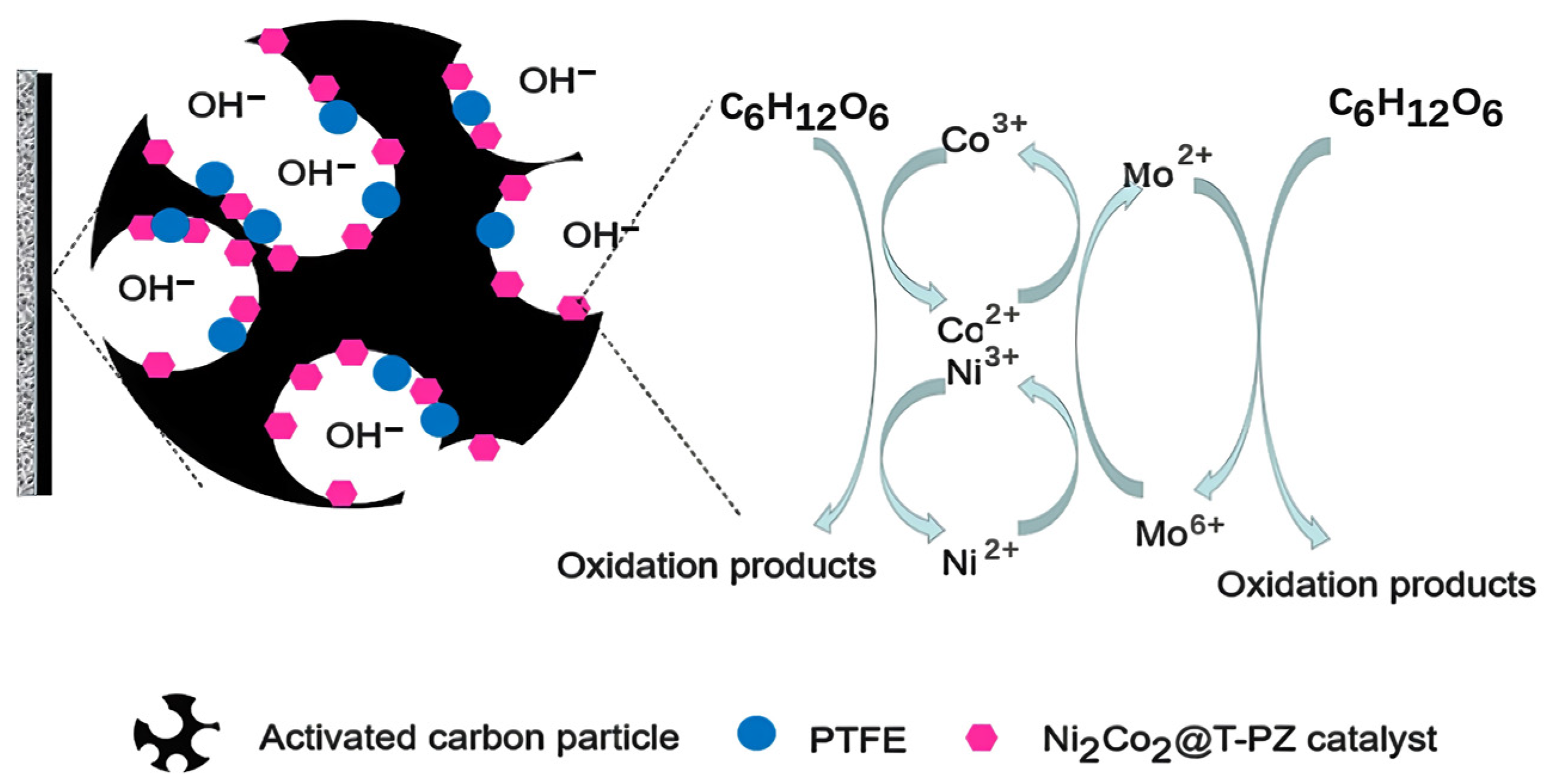
2.3. Catalytic Mechanism

SEM, XPS, XRD, and electrochemical characterization results can be used to infer the catalytic mechanism of glucose oxidation by Ni2Co2@T-PZ in alkaline environment. The catalytic process can involve the following steps [40,41,42,43,44,45]:
24 Co2+ − 24 e → 24 Co3+
C6H12O6 + 36 OH + 24 Co3+ → 6CO32− + 24 Co2+ + 24 H2O
24 Ni2+ − 24 e → 24 Ni3+
C6H12O6 + 36 OH + 24 Ni3+ → 6CO32− + 24 Ni2+ + 24 H2O
6 Mo6+ + 12 e → 6 Mo4+
6 Mo4+ + 12 e → 6 Mo2+
C6H12O6 +36 OH + 6 Mo6+ → 6CO32− + 6 Mo2+ + 24 H2O
Mo6+ + 2 Co2+ → Mo4+ + 2 Co3+
Mo6+ + 2 Ni2+ → Mo4+ + 2 Ni3+
Co3+ and Ni3+ generated from Co2+ and Ni2+ have a high oxidative state, which can accelerate the oxidation process of glucose under alkaline environment. Mo6+ has great tendency to acquire electrons from neighbor molecules. Firstly, it can react with Co2+ and Ni2+ to produce Co3+ and Ni3+. In addition, it can directly capture electrons from glucose and be reduced to Mo2+. Figure 8 depicts the possible reaction processes that Ni2Co2@T-PZ involved in the oxidation of glucose. There may exist a synergistic effect between Co2+, Ni2+, and Mo6+: with the good oxidizing property of Mo6+, Co3+, and Ni3+ being easily obtained, and Co3+ and Ni3+ being re-reduced to Co2+ and Ni2+ by oxidizing glucose. Meanwhile, there is a synergistic effect between reactions (1) and (3), Ni3+ has the ability to capture electrons from glucose, and Co2+ can play a facilitating role. The resulting Mo2+ is oxidized to Mo6+ via the cathodic transfer of electrons, resulting in catalyst recycling [46,47]. In addition, there is a good synergistic effect between POM and ZIF-67, so Ni2Co2@T-PZ catalyst has a high specific surface area and abundant active sites, and also has excellent diffusion efficiency. The Ni2Co2@T-PZ catalyst showed excellent catalytic performance for glucose oxidation [48,49].

3. Materials and Methods

3.1. Materials

Nickel foam was obtained from Yilongsheng Energy Technology Co., Ltd. (Suzhou, China). Activated Carbon (AC) powder (YEC-8A) was purchased from Yihuan Carbon Co., Ltd. (Fuzhou, China). A 60 wt% PTFE solution was purchased from Hesen Inc. (Shanghai, China). Phosphomolybdic acid hydrate (PMo12) and 2-methylimidazole were purchased from Kemiou (Tianjin, China). Glucose, KOH, and all the other chemicals were analytically pure. Deionized water (DI) was used as the solvent for all the solutions.

3.2. Characterization

Electrochemical characterization was carried out on a CHI-660E electrochemical workstation (Chenhua Instrument Co., Ltd., Shanghai, China). The microstructure of the samples was analyzed on a SEM (S4800, Hitachi High-tech Corporation, Tokyo, Japan) and a TEM (Tecnai G2 F20, IKA, Königswinter, Germany). X-ray diffraction (XRD) patterns were measured by a D/MX-IIIA X-ray diffractometer (Rigaku, Japan). XPS analysis was carried out on an Escalab 250Xi X-ray photoelectron spectrometer (Thermo Fisher Scientific, Waltham, MA, USA).

3.3. Preparation of Electrodes

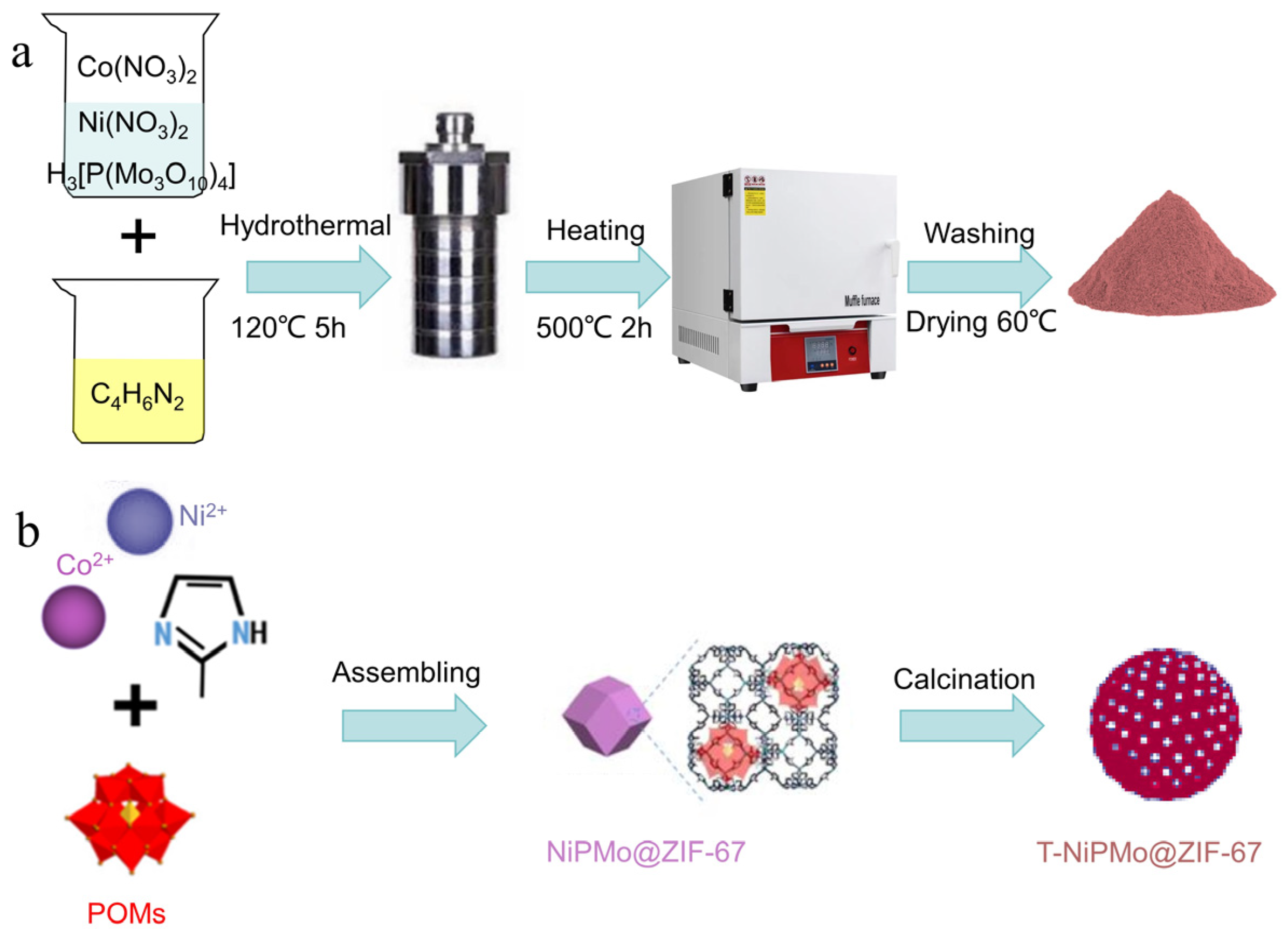
3.3.1. Preparation of XPMo@ZIF-67 and NixCoy@PZ

An amount of 2.5 mM cobalt nitrate, together with 2.5 mM different transitional metal salts (copper nitrate, ferric nitrate, nickel nitrate or zinc nitrate), was added into 25 mL of methanol. After fully mixing, 10 mL of 30 mM phosphomolybdate aqueous solution was added into the bottle to obtain solution A (denoted as A1, A2, A3, and A4, respectively). Solution B was prepared by adding 20 mM 2-methylimidazole into 25 mL methanol. Solutions C was obtained by quickly mixing solution A with solution B (denoted as C1, C2, C3, and C4, respectively). Then, the mixture was heated in a hydrothermal reactor (10 h, 120 °C). Afterwards, purple precipitates were obtained. The obtained precipitates were filtered, and then were washed with ethyl alcohol. The precipitates were dried in a 60 °C oven overnight to obtain CuPMo@ZIF-67, FePMo@ZIF-67, NiPMo@ZIF-67, and ZnPMo@ZIF-67, respectively.
To prepare NixCoy@PZ, the Ni2+/Co2+ ratio was modified during the preparation of NiPMo@ZIF-67. The amounts of 0.6 mM nickel nitrate and 1.9 mM cobalt nitrate, 1.25 mM nickel nitrate and 1.25 mM cobalt nitrate, 1.9 mM nickel nitrate and 0.6 mM cobalt nitrate, and 2.5 mM nickel nitrate were dissolved in 25 mL methanol solution, respectively to obtain Ni1Co3@PZ, Ni2Co2@PZ, Ni3Co1@PZ, and Ni@PZ, respectively.

3.3.2. Preparation of T-XPMo@ZIF-67 and NixCoy@T-PZ

XPMo@ZIF-67 was placed into the Muffle furnace and slowly heated to 500 °C for 2 h. After it cooled down to room temperature, the synthesized products were washed with ethyl alcohol, and the precipitates were dried in a 60 °C oven to obtain T-NiPMo@ZIF-67, T-CuPMo@ZIF-67, T-FePMo@ZIF-67, T-ZnPMo@ZIF-67, respectively. The whole procedure of the preparation of T-NiPMo@ZIF-67, as well as the schematic diagram, were depicted in Figure 9a,b, respectively.
NixCoy@T-PZ was prepared using the same procedure from NixCoy@PZ, and was denoted as Ni1Co3@T-PZ, Ni2Co2@T-PZ, Ni3Co1@T-PZ, and Ni@T-PZ, respectively.

3.3.3. Preparation of T-XPMo@ZIF-67 and NixCoy@PZ Modified Anode

The T-XPMo@ZIF-67 and NixCoy@PZ modified anodes were prepared by rolling method as previously described [23]. The detail procedure is as follows:
(1)
An amount of 0.5 g of activated carbon was mixed with T-XPMo@ZIF-67/NixCoy@PZ in a ratio of 1:0.01~1:0.05 by using anhydrous ethanol as solvent. The obtained mixture was placed in an ultrasonic cleaner with ultrasonic shaking and constant stirring for 40 min;
(2)
An amount of 0.25 g PTFE emulsion (60 wt%) was slowly added, and stirred continuously for 40 min;
(3)
The mixture was placed in a thermostatic water bath at 70 °C, and stirred continuously;
(4)
The catalyst modified anode with a thickness of 2~4 mm was obtained by rolling the mixture onto a Ni foam disc (diameter: 36 mm).
The blank control anode was prepared by using the same procedure with 0.5 g activated carbon powder.

3.4. Experimental Methods

The fuel cell was mainly made of polymethyl methylbenzoate (PMMA), with carbon cloth and nickel foam seals at both ends as the cathode and anode. An amount of 10 mL of 1 M glucose in 3 M KOH solution was used as substrate. The water used in the experiment was deionized water. A three-electrode system was employed in the electrochemical experiment. The reference electrode was saturated HgO electrode, the counter electrode was carbon cloth, and the working electrode was catalyst modified activated carbon/nickel foam. For the characterization of whole-cell performance (polarization curves and power density curves of the fuel cell), the fuel cell was assembled with a NixCoy@T-PZ doped anode and an active carbon air-cathode [44,45]. When placing the air cathode, we made sure that the catalytic layer of the air cathode faced the inner cavity of the fuel cell. The catalyst modified anode and the air cathode were pressed tightly with the rubber gasket to make them fully in contact with the nickel wire. After assembling the fuel cell, we checked whether there was water leakage and air tightness. Then, the glucose and KOH were injected into the inner cavity of the fuel cell from the inlet port on the side of the fuel cell, and the nitrogen was quickly vented for 10 min, so that the residual oxygen in the fuel cell chamber was discharged. The outlet was water-sealed during the exhaust process, and continuous small bubbles could be observed. After passing nitrogen, we sealed the air inlet and outlet of the fuel cell to prevent oxygen in the air from entering the fuel cell directly through these two ports. The temperature of the test environment was 23 ℃ ± 2 ℃. The change of fuel cell voltage was measured in real time, and various electrochemical parameters were measured when the open circuit voltage was stable.

4. Conclusions

In this paper, a series of efficient catalysts for glucose oxidation were prepared by doping transitional metals into nanohybrids of PMo and ZIF-67. The doping of Ni2+ could significantly improve the electrochemical performance of T-PMo@ZIF-67. Among them, Ni2Co2@T-PZ showed the best performance. The maximum power density of the glucose cell doped with Ni2Co2@T-PZ catalyst reached 34.065 W m−2, which was much higher than that of conventional cobalt-molybdenum-nickel oxides. The characterization results by SEM, XPS, and XRD indicate that Ni2Co2@T-PZ is a nanohybrid, being composed of Co3O4, CoMoO4, CoNiO4, and MoNiO4. Ni2Co2@T-PZ maintains the hollow structure of ZIF-67, and there is a synergistic effect between Co2+, Ni2+, and Mo6+ for glucose oxidation. This work has considerable application prospects in the field of electrochemistry.

Supplementary Materials

The following supporting information can be downloaded at: https://www.mdpi.com/article/10.3390/catal14010019/s1. Figure S1: Equivalent circuit diagram; Figure S2: EDS image of Ni2Co2@T-PZ.

Author Contributions

Writing—original draft preparation, S.J. and N.K.; methodology, Y.Z. and Y.L.; data curation, M.L. and B.M.; conceptualization, N.K., X.Z. and X.L.; writing—review and editing, P.Z. and X.L. All authors have read and agreed to the published version of the manuscript.

Funding

This work was partially financially supported by the National Natural Science Foundation of China (No. 42377380) and the National Key R&D Program of China (Grant No. 2019YFC1407800).

Data Availability Statement

The data presented in this study are available on request from the corresponding author.

Conflicts of Interest

Authors have no conflict of interest to declare.

References

  1. Li, B.; Wen, H.-M.; Cui, Y.; Zhou, W.; Qian, G.; Chen, B. Emerging Multifunctional Metal-Organic Framework Materials. Adv. Mater. 2016, 28, 8819–8860. [Google Scholar] [CrossRef] [PubMed]
  2. Liu, D.; Wan, J.; Pang, G.; Tang, Z. Hollow Metal-Organic- Framework Micro/Nanostructures and their Derivatives: Emerging Multifunctional Materials. Adv. Mater. 2019, 31, 1803291. [Google Scholar] [CrossRef] [PubMed]
  3. Zhu, L.; Liu, X.-Q.; Jiang, H.-L.; Sun, L.-B. Metal-Organic Frameworks for Heterogeneous Basic Catalysis. Chem. Rev. 2017, 117, 8129–8176. [Google Scholar] [CrossRef] [PubMed]
  4. Singh, R.; Singh, G.; George, N.; Singh, G.; Gupta, S.; Singh, H.; Kaur, G.; Singh, J. Copper-Based Metal-Organic Frameworks (MOFs) as an Emerging Catalytic Framework for Click Chemistry. Catalysts 2023, 13, 130. [Google Scholar] [CrossRef]
  5. Kang, Y.-S.; Lu, Y.; Chen, K.; Zhao, Y.; Wang, P.; Sun, W.-Y. Metal-organic frameworks with catalytic centers: From synthesis to catalytic application. Coordin. Chem. Rev. 2019, 378, 262–280. [Google Scholar] [CrossRef]
  6. Zhang, H.; Osgood, H.; Xie, X.; Shao, Y.; Wu, G. Engineering nanostructures of PGM-free oxygen-reduction catalysts using metal-organic frameworks. Nano Energy 2017, 31, 331–350. [Google Scholar] [CrossRef]
  7. Liu, Y.; Zhao, P.; Duan, C.; He, C. Three-Dimensional Neodymium Metal-Organic Framework for Catalyzing the Cyanosilylation of Aldehyde and the Synthesis of 2,3-Dihydroquinazolin-4(1H)-one Derivatives. Inorg. Chem. 2023, 62, 10359–10368. [Google Scholar] [CrossRef]
  8. Zhang, J.; Huang, Y.; Li, G.; Wei, Y. Recent Recent advances in alkoxylation chemistry of polyoxometalates: From synthetic strategies, structural overviews to functional applications. Coordin. Chem. Rev. 2019, 378, 395–414. [Google Scholar] [CrossRef]
  9. Liu, J.-X.; Zhang, X.-B.; Li, Y.-L.; Huang, S.-L.; Yang, G.-Y. Polyoxometalate functionalized architectures. Coordin. Chem. Rev. 2020, 414, 213260. [Google Scholar] [CrossRef]
  10. Gumerova, N.I.; Rompel, A. Synthesis, structures and applications of electron-rich polyoxometalates. Nat. Rev. Chem. 2018, 2, 0112. [Google Scholar] [CrossRef]
  11. Zhang, Z.; Ma, X.; Han, X.; Cui, H.; Lu, Y.; Liu, S.; Liu, Y. Straightforward construction of hollow polyoxometalate-based metal-organic framework via pseudo-homoepitaxial growth. Sci. China Chem. 2022, 65, 1921–1928. [Google Scholar] [CrossRef]
  12. Yang, H.; Li, J.; Zhang, H.; Lv, Y.; Gao, S. Facile synthesis of POM@MOF embedded in SBA-15 as a steady catalyst for the hydroxylation of benzene. Micropor. Mesopor. Mat. 2014, 195, 87–91. [Google Scholar] [CrossRef]
  13. Du, D.-Y.; Qin, J.-S.; Li, S.-L.; Su, Z.-M.; Lan, Y.-Q. Recent advances in porous polyoxometalate-based metal-organic framework materials. Chem. Soc. Rev. 2014, 43, 4615–4632. [Google Scholar] [CrossRef] [PubMed]
  14. Mialane, P.; Mellot-Draznieks, C.; Gairola, P.; Duguet, M.; Benseghir, Y.; Oms, O.; Dolbecq, A. Heterogenisation of polyoxometalates and other metal-based complexes in metal-organic frameworks: From synthesis to characterisation and applications in catalysis. Chem. Soc. Rev. 2021, 50, 6152–6220. [Google Scholar] [CrossRef] [PubMed]
  15. Sun, J.; Abednatanzi, S.; Van Der Voort, P.; Liu, Y.-Y.; Leus, K. POM@MOF Hybrids: Synthesis and Applications. Catalysts 2020, 10, 578. [Google Scholar] [CrossRef]
  16. Freire, C.; Fernandes, D.M.; Nunes, M.; Abdelkader, V.K. POM & MOF-based Electrocatalysts for Energy-related Reactions. Chemcatchem 2018, 10, 1703–1730. [Google Scholar]
  17. Liu, J.; Huang, M.; Hua, Z.; Dong, Y.; Feng, Z.; Sun, T.; Chen, C. Polyoxometalate-Based Metal Organic Frameworks: Recent Advances and Challenges. ChemistrySelect 2022, 7, e202200546. [Google Scholar] [CrossRef]
  18. Tiba, S.; Omri, A. Literature survey on the relationships between energy, environment and economic growth. Renew Sust. Energy Rev. 2017, 69, 1129–1146. [Google Scholar] [CrossRef]
  19. Nathaniel, S.P.; Adeleye, N. Environmental preservation amidst carbon emissions, energy consumption, and urbanization in selected african countries: Implication for sustainability. J. Clean. Prod. 2021, 285, 125409. [Google Scholar] [CrossRef]
  20. Ehsanullah, S.; Quyen Ha, T.; Sadiq, M.; Bashir, S.; Mohsin, M.; Iram, R. How energy insecurity leads to energy poverty? Do environmental consideration and climate change concerns matters. Environ. Sci. Pollut. Res. 2021, 28, 55041–55052. [Google Scholar] [CrossRef]
  21. Wang, J.; Zhang, X.; Li, Y.; Liu, P.; Chen, X.; Zhang, P.; Wang, Z.; Liu, X. Sweet Drinks as Fuels for an Alkaline Fuel Cell with Nonprecious Catalysts. Energies 2021, 14, 206. [Google Scholar] [CrossRef]
  22. Liu, T. Glucose Fuel Cells and Membranes: A Brief Overview and Literature Analysis. Sustainability 2022, 14, 8376. [Google Scholar] [CrossRef]
  23. Kerzenmacher, S.; Ducree, J.; Zengerle, R.; von Stetten, F. Energy harvesting by implantable abiotically catalyzed glucose fuel cells. J. Power Sources 2008, 182, 1–17. [Google Scholar] [CrossRef]
  24. Antolini, E. External abiotic glucose fuel cells. Sustain. Energy Fuels. 2021, 5, 5038–5060. [Google Scholar] [CrossRef]
  25. Do, U.P.; Seland, F.; Johannessen, E.A. A micro fuel cell for abiotical catalysis of glucose. J. Power Sources. 2020, 478, 229032. [Google Scholar] [CrossRef]
  26. Ho, J.; Li, Y.; Dai, Y.; Kim, T.; Wang, J.; Ren, J.; Yun, H.; Liu, X. Ionothermal synthesis of N-doped carbon supported CoMn2O4 nanoparticles as ORR catalyst in direct glucose alkaline fuel cell. Int. J. Hydrogen Energy 2021, 46, 20503–20515. [Google Scholar] [CrossRef]
  27. Huang, J.; Simons, P.; Sunada, Y.; Rupp, J.L.M.; Yagi, S. Pt-Catalyzed D-Glucose Oxidation Reactions for Glucose Fuel Cells. J. Electrochem. Soc. 2021, 168, 064511. [Google Scholar] [CrossRef]
  28. Dong, F.; Liu, X.; Irfan, M.; Yang, L.; Li, S.; Ding, J.; Li, Y.; Khan, I.U.; Zhang, P. Macaroon-like FeCo2O4 modified activated carbon anode for enhancing power generation in direct glucose fuel cell. Int. J. Hydrogen Energy 2019, 44, 8178–8187. [Google Scholar] [CrossRef]
  29. Zhao, Y.; Liu, X.; Wang, X.; Zhang, P.; Shi, J. Peony petal-like 3D graphene-nickel oxide nanocomposite decorated nickel foam as high-performance electrocatalyst for direct glucose alkaline fuel cell. Int. J. Hydrogen Energy 2017, 42, 29863–29873. [Google Scholar] [CrossRef]
  30. Irfan, M.; Liu, X.; Li, S.; Khan, I.U.; Li, Y.; Wang, J.; Wang, X.; Du, X.; Wang, G.; Zhang, P. High-performance glucose fuel cell with bimetallic Ni-Co composite anchored on reduced graphene oxide as anode catalyst. Renew Energy 2020, 155, 1118–1126. [Google Scholar] [CrossRef]
  31. Yang, L.; Liu, X.; Ding, J.; Li, S.; Dong, F.; Irfan, M.; Li, Y.; Wang, G.; Du, X.; Zhang, P. Chlorella-derived porous heteroatom-doped carbons as robust catalysts for oxygen reduction reaction in direct glucose alkaline fuel cell. Int. J. Hydrogen Energy 2019, 44, 2823–2831. [Google Scholar] [CrossRef]
  32. Li, Y.; Dong, F.; Jiao, S.; Wang, J.; Dai, Y.; Irfan, M.; Liu, X. Co2+-P(W3O10)(4)(3-) modified activated carbon as an efficient anode catalyst for direct glucose alkaline fuel cell. Int. J. Hydrogen Energy 2022, 47, 22952–22962. [Google Scholar] [CrossRef]
  33. Akhairi, M.A.F.; Kamarudin, S.K. Catalysts in direct ethanol fuel cell (DEFC): An overview. Int. J. Hydrogen Energy 2016, 41, 4214–4228. [Google Scholar] [CrossRef]
  34. Din, M.A.U.; Idrees, M.; Jamil, S.; Irfan, S.; Nazir, G.; Mudassir, M.A.; Saleem, M.S.; Batool, S.; Cheng, N.; Saidur, R. Advances and challenges of methanol-tolerant oxygen reduction reaction electrocatalysts for the direct methanol fuel cell. J. Energy Chem. 2023, 77, 499–513. [Google Scholar] [CrossRef]
  35. Gong, L.; Yang, Z.; Li, K.; Xing, W.; Liu, C.; Ge, J. Recent development of methanol electrooxidation catalysts for direct methanol fuel cell. J. Energy Chem. 2018, 27, 1618–1628. [Google Scholar] [CrossRef]
  36. Oncescu, V.; Erickson, D. High volumetric power density, non-enzymatic, glucose fuel cells. Sci. Rep. 2013, 3, 1226. [Google Scholar] [CrossRef] [PubMed]
  37. Simons, P.; Schenk, S.A.; Gysel, M.A.; Olbrich, L.F.; Rupp, J.L.M. A Ceramic-Electrolyte Glucose Fuel Cell for Implantable Electronics. Adv. Mater. 2022, 34, 2109075. [Google Scholar] [CrossRef]
  38. Su, C.-H.; Sun, C.-L.; Peng, S.-Y.; Wu, J.-J.; Huang, Y.-H.; Liao, Y.-C. High performance non-enzymatic graphene-based glucose fuel cell operated under moderate temperatures and a neutral solution. J. Taiwan Inst. Chem. E 2019, 95, 48–54. [Google Scholar] [CrossRef]
  39. Guo, H.; Yin, H.; Yan, X.; Shi, S.; Yu, Q.; Cao, Z.; Li, J. Pt-Bi decorated nanoporous gold for high performance direct glucose fuel cell. Sci. Rep. 2016, 6, 39162. [Google Scholar] [CrossRef]
  40. Lv, Z.; Zhong, Q.; Bu, Y. Controllable synthesis of Ni-Co nanosheets covered hollow box via altering the concentration of nitrate for high performance supercapacitor. Electrochim. Acta 2016, 215, 500–505. [Google Scholar] [CrossRef]
  41. Liu, H.; Jin, M.; Zhan, D.; Wang, J.; Cai, X.; Qiu, Y.; Lai, L. Stacking faults triggered strain engineering of ZIF-67 derived Ni-Co bimetal phosphide for enhanced overall water splitting. Appl. Catal. B-Environ. 2020, 272, 118951. [Google Scholar] [CrossRef]
  42. Guo, G.; Li, W.; Ahmed, T.; Hu, D.; Cui, R.; Zhang, B.; Zhang, X. Production of liquid fuels from Kraft lignin over bimetallic Ni-Mo supported on ZIF-derived porous carbon catalyst. RSC Adv. 2021, 11, 37932–37941. [Google Scholar] [CrossRef] [PubMed]
  43. Yang, X.-L.; Ye, Y.-S.; Wang, Z.-M.; Zhang, Z.-H.; Zhao, Y.-L.; Yang, F.; Zhu, Z.-Y.; Wei, T. POM-Based MOF-Derived Co3O4/CoMoO4Nanohybrids as Anodes for High-Performance Lithium-Ion Batteries. ACS Omega 2020, 5, 26230–26236. [Google Scholar] [CrossRef] [PubMed]
  44. Gao, M.; Liu, X.; Irfan, M.; Shi, J.; Wang, X.; Zhang, P. Nickle-cobalt composite catalyst-modified activated carbon anode for direct glucose alkaline fuel cell. Int. J. Hydrogen Energy 2018, 43, 1805–1815. [Google Scholar] [CrossRef]
  45. Irfan, M.; Khan, I.U.; Wang, J.; Li, Y.; Liu, X. 3D porous nanostructured Ni3N-Co3N as a robust electrode material for glucose fuel cell. RSC Adv. 2020, 10, 6444–6451. [Google Scholar] [CrossRef] [PubMed]
  46. Wang, Y.; Wang, Y.; Zhang, L.; Liu, C.-S.; Pang, H. Core-shell-type ZIF-8@ZIF-67@POM hybrids as efficient electrocatalysts for the oxygen evolution reaction. Inorg. Chem. Front. 2019, 6, 2514–2520. [Google Scholar] [CrossRef]
  47. Abdelkader-Fernandez, V.K.; Fernandes, D.M.; Balula, S.S.; Cunha-Silva, L.; Freire, C. Oxygen Evolution Reaction Electrocatalytic Improvement in POM@ZIF Nanocomposites: A Bidirectional Synergistic Effect. ACS Appl. Energy Mater. 2020, 3, 2925–2934. [Google Scholar] [CrossRef]
  48. Tang, Y.; Zou, Z.; Wu, X.; Zuo, P.; Wang, L.; Huang, G.; Zhu, J.; Zhong, S. ZIF-67@POM hybrid-derived unique willow-shaped two-dimensional Mo-CoP nanostructures as efficient electrocatalysts for the oxygen evolution reaction. New J. Chem. 2023, 47, 9887–9893. [Google Scholar] [CrossRef]
  49. Abdelkader-Fernandez, V.K.; Fernandes, D.M.; Balula, S.S.; Cunha-Silva, L.; Freire, C. Advanced framework-modified POM@ZIF-67 nanocomposites as enhanced oxygen evolution reaction electrocatalysts. J. Mater. Chem. A 2020, 8, 13509–13521. [Google Scholar] [CrossRef]
Figure 1. (a) LSV diagram of T-XPMo@ZIF-67 doped anodes; (b) LSV diagram of NixCoy@ZIF-67 doped anodes (10 mL 3 M of KOH and 1 M of glucose solution).
Catalysts 14 00019 g001
Figure 2. (a) EIS diagram of the different T-XPMo@ZIF-67 anodes; (b) EIS diagram of the NixCoy@T-PZ anodes (10 mL 3 M of KOH and 1 M of glucose solution).
Catalysts 14 00019 g002
Figure 3. (a) Tafel curves of the NixCoy@T-PZ anodes; (b) Tafel curve fitting results for different NixCoy@T-PZ anodes (10 mL 3 M of KOH and 1 M of glucose solution).
Catalysts 14 00019 g003
Figure 4. (a) Polarization and power density curves of the fuel cell equipped with different NixCoy@T-PZ doped anodes (The blank sign represents the power density curves of alkaline glucose fuel cells constructed with air cathodes and different catalytic anodes, and the filled sign represents the current density and open circuit voltage of the alkaline glucose fuel cells.); (b) Individual cathode and anode polarization curves (10 mL 3 M of KOH and 1 M of glucose solution).
Catalysts 14 00019 g004
Figure 5. (a) SEM image of Ni2Co2@T-PZ. (b) Element diagram of Ni2Co2@T-PZ.
Catalysts 14 00019 g005
Figure 6. XRD pattern of T-PMo@ZIF-67 and Ni2Co2@ZIF-67.
Catalysts 14 00019 g006
Figure 7. (a) Full spectrum of XPS for Ni2Co2@ZIF-67; (b) C1s spectra; (c) Mo3d spectra; (d) Co2p spectra; (e) Ni2p spectra.
Catalysts 14 00019 g007
Figure 8. Mechanism diagram of Ni2Co2@T-PZ catalyzed glucose oxidation.
Catalysts 14 00019 g008
Figure 9. (a) The flow chart of the preparation of T-NiPMo@ZIF-67; (b) The schematic diagram of the preparation of T-NiPMo@ZIF-67.
Catalysts 14 00019 g009
Table 1. Impedance values of T-XPMo@ZIF-67 anodes.
ACT-CuPMo@ZIF-67T-FePMo@ZIF-67T-NiPMo@ZIF-67T-ZnPMo@ZIF-67T-PMo@ZIF-67
Rs (Ω)1.5181.0021.1620.6861.680.7869
Rct (Ω)1.1510.41880.65940.17552.6430.3063
Rd (Ω)1.9570.73330.74160.2012.4030.3212
Rt (Ω)4.6262.15412.5631.06256.7261.4144
Table 2. Impedance values of NixCoy@T-PZ anodes.
Ni@T-PZNi1Co3@T-PZNi3Co1@T-PZNi2Co2@T-PZT-PMo@ZIF-67
Rs (Ω)1.0060.8870.7380.6860.7869
Rct (Ω)0.75820.45770.2020.17550.3063
Rd (Ω)0.9670.87110.24670.2010.3212
Rt (Ω)2.73122.21581.18671.06251.4144
Table 3. Tafel curve fitting results.
Fitting EquationR2Tafel
(mV dec−1)
10−4I0
(A cm−2)
ACy = 5.37143 × −3.416730.9983186.17023.831
Ni@T-PZy = 5.41948 × −3.081810.99818184.51958.283
Ni3Co1@T-PZy = 5.05714 × −2.457160.99876197.740234.901
Ni2Co2@T-PZy = 5.14286 × −2.421540.99758194.444337.884
Ni1Co3@T-PZy = 5.21818 × −2.994960.99807191.637710.117
T-PMo@ZIF-67y = 4.82208 × −2.610370.99766207.379424.526
Table 4. Performance of glucose fuel cells with different electrodes and catalysts.
AnodeCathodeCatalystPower DensityReference
NiAlPt2 μW cm−2;[36]
PtPtPt43 μW cm−2;[37]
PtPd/grapheneN-doped graphene oxide nanoribbonsPt24.9 µW cm−2;[38]
Nanoporous goldPt/CPt/Bi8 mW cm−2;[39]
Activated carbon/Ni-foamActivated carbon/Ni-foamNi2Co2@T-PMo@ZIF-673.4 mW cm−2;This work
Disclaimer/Publisher’s Note: The statements, opinions and data contained in all publications are solely those of the individual author(s) and contributor(s) and not of MDPI and/or the editor(s). MDPI and/or the editor(s) disclaim responsibility for any injury to people or property resulting from any ideas, methods, instructions or products referred to in the content.

