
Interfacial Electronic Engineering of NiSe–Anchored Ni–N–C Composite Electrocatalyst for Efficient Hydrogen Evolution
State Key Laboratory of Heavy Oil Processing, China University of Petroleum, Beijing 102249, China
*
Authors to whom correspondence should be addressed.
†
These authors contributed equally to this work.
Catalysts 2022, 12(12), 1525; https://doi.org/10.3390/catal12121525
Submission received: 11 October 2022
/
Revised: 22 November 2022
/
Accepted: 23 November 2022
/
Published: 26 November 2022
(This article belongs to the Special Issue Featured Papers in Electrochemistry and Electrocatalysis in China)
Abstract
:Rational design and construction of cost–effective electrocatalysts for efficient hydrogen production has attracted extensive research attention worldwide. Herein, we report the construction of a transition metal selenide/carbon composite catalyst featuring uniform NiSe nanoparticles anchored to single Ni atom doped porous carbon structure (NiSe/Ni–N–C) via a facile one–pot pyrolysis of low–cost solid mixtures. NiSe/Ni–N–C exhibits remarkable catalytic performance towards hydrogen evolution reaction (HER) in 1.0 M KOH, requiring a low overpotential of 146 mV to reach a current density of 10 mA cm−2. The unique carbon layer encapsulation derived from the enwrapping of fluid catalytic cracking slurry further renders NiSe/Ni–N–C excellent for long–term durability in electrolyte corrosion and nanostructure aggregation. This work paves the way for the design and synthesis of highly efficient composite HER electrocatalysts.
1. Introduction
The exploitation and combustion of conventional fossil energy sources has brought about the overwhelming global warming and energy crisis [1,2]. Therefore, it is of urgent demand to develop clean and sustainable alternatives. Among them, hydrogen is widely regarded as the “ultimate power” due to its high energy density, large reserves on Earth, and complete cleanness due to the only combustion product being water [3,4,5]. At the current stage, the industrial mass production of hydrogen is still dominated by steam reforming, leading to inevitable carbon emission and deteriorated purity [6]. In comparison, hydrogen evolution from electrocatalytic water splitting emerges as a promising strategy to produce high–purity hydrogen in an environmental–friendly manner [7,8,9,10]. Until now, the benchmark electrocatalysts for the two half reactions, namely hydrogen evolution reaction (HER) and oxygen evolution reaction (OER), have been platinum group materials and ruthenium/iridium oxides [11,12,13]. However, high cost and limited supply dramatically hinders the widespread application of these noble metal electrocatalysts.
Transition metal selenides (TMSes) have been widely researched as promising HER electrocatalyst alternatives to Pt group materials [14,15,16]. Specifically, compared to other natural and abundant transition–metal–based catalysts, the more metal–like selenium atoms endow TMSes with good electrical conductivity [17]. Moreover, TMSes also have the advantages of simple preparation, superior catalytic activity, and excellent stability. However, two major drawbacks dramatically hinder the practical application of TMSes: (1) TMSes are usually located on the right side of the volcano plot, with too weak interaction with H* (Gibbs free energy of hydrogen adsorption ΔGH* > 0) [18], indicating inferior catalytic activity for intrinsic bulk TMSes. (2) The catalytic performance of TMSes degrades rapidly during long–time electrocatalysis due to severe electrochemical corrosion [19].
To address these issues, various strategies have been developed. The construction of nanostructured TMSes was reported to not only significantly improve the exposure of active sites, but also effectively tune the electronic structures compared to the bulk counterpart [19,20]. In addition, due to the quantum confinement effects, the bandgap of TMSes gradually transforms from indirect to direct, leading to higher conductivity of nanosized materials [14]. For instance, uniform sea urchin–like NiSe nanofiber was synthesized with massive exposed electrochemical active surface area (ECSA), and the constructed unique, loose, spiny structure further improved the HER activity with more active catalytic surface structure [21]. Moreover, the highly porous NiSe2 nanosheets prepared by selective etching and subsequent selenization of layered double hydroxide exhibited superior HER activity in both acid and base, with abundant exposed surface area and edge structures [22].
However, nanostructured TMSes tend to aggregate back to bulk phase to minimize surface energy, leading to significant degradation of active sites and catalytic activity. Therefore, to improve the long–term stability of TMSes during long–term electrocatalysis, compositing with carbon backbone has been reported to be an effective strategy. On one hand, the encapsulation of carbon layers mitigates the re–aggregation of nanostructures, thus maintaining the morphology integrity [23,24]. On the other hand, the chemically inert carbon isolates the active sites from the corrosion of the electrolytes [25,26]. Moreover, the highly conductive carbon framework also acts as the electron collector for promoted electron dissipation and transfer [20,27]. With deliberate heteroatom doping, the carbon backbone demonstrates dramatically improved intrinsic catalytic activities [28,29]. For the past few years, the single atom catalyst (SAC) has emerged as a new type of carbon–based electrocatalyst in which each heteroatom is separated anchored in the carbon backbone to reach the maximum exposure and utilization of catalytic sites [30,31]. Yang et al. reported [32] a highly efficient Pt–C3 HER electrocatalyst by trapping single Pt atoms in the constructed single vacancies of carbon backbones. Furthermore, the synthesis of SACs also involves the pyrolysis of precursors with the pre–chelated metal centers. For instance, Fan et al. synthesized [33] atomically isolated nickel anchored graphitic carbon through the pyrolysis of a Ni–based metal–organic framework. The N coordination stabilized the single atomic sites and effectively regulated the electronic structure of the catalyst to realize the remarkable HER performance. Nevertheless, while several TMSe/SAC composites have been reported to show good catalytic activity, the interaction and charge transfer at the heterostructure interface, as well as the synergistic effect between active sites, are barely elaborated.
Graphitic carbon nitride (g–C3N4) is a novel two–dimensional material composed of triazine rings and tri–s–triazine (heptazine) rings as its basic unit. The appropriate band gap of 2.7 eV makes it a promising candidate in photocatalysis [34], and it has been reported that C3N4–based nanostructures showed high activity towards various electrocatalysis [35]. In addition, C3N4 with a large specific area can be employed as the self–sacrificing template for pore generation [36]. Meanwhile, C3N4 introduces abundant N heteroatoms into the porous structure with the N–rich gas from self–decomposing [37].
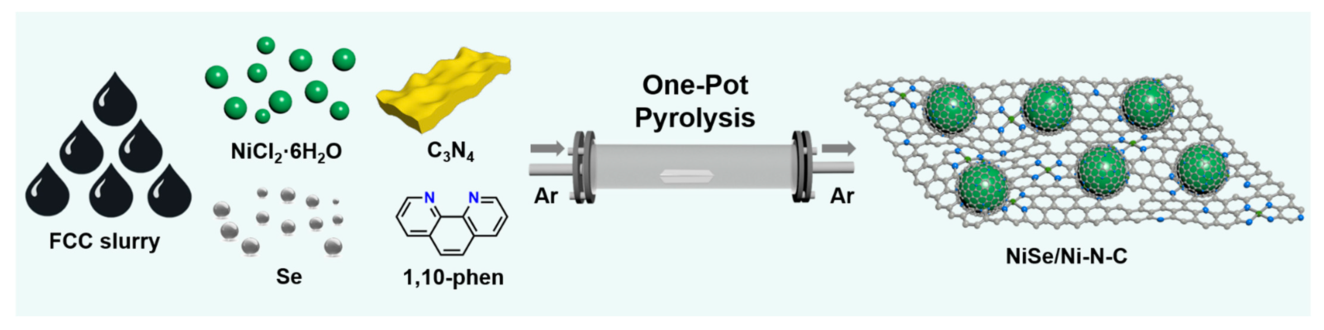
Herein, we report the novel construction of a TMSe/SAC composite with single atomic Ni doped carbon and the supported NiSe nanoparticle (NP) (NiSe/Ni–N–C) as efficient HER electrocatalyst. The synthesis features facile one–pot pyrolysis of NiCl2·6H2O, 1,10–phenanthroline, graphitic C3N4, selenium powder, and fluid catalytic cracking (FCC) slurry. NiSe/Ni–N–C demonstrates good activity towards electrocatalytic HER in a 1.0 M KOH electrolyte, with low overpotential of 146 mV to reach a current density of 10 mA cm−2. The encapsulation of the carbon layer also ensures excellent long–term electrocatalytic stability. Further investigation reveals the apparent charge transfer at the NiSe/Ni–N–C interface to regulate the electronic structure of both active species, thus achieving the optimized H* adsorption behavior. This work paves the way for the rational design and synthesis of transition metal/carbon composite HER electrocatalyst for efficient hydrogen evolution.
2. Results
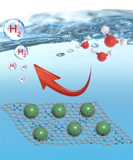
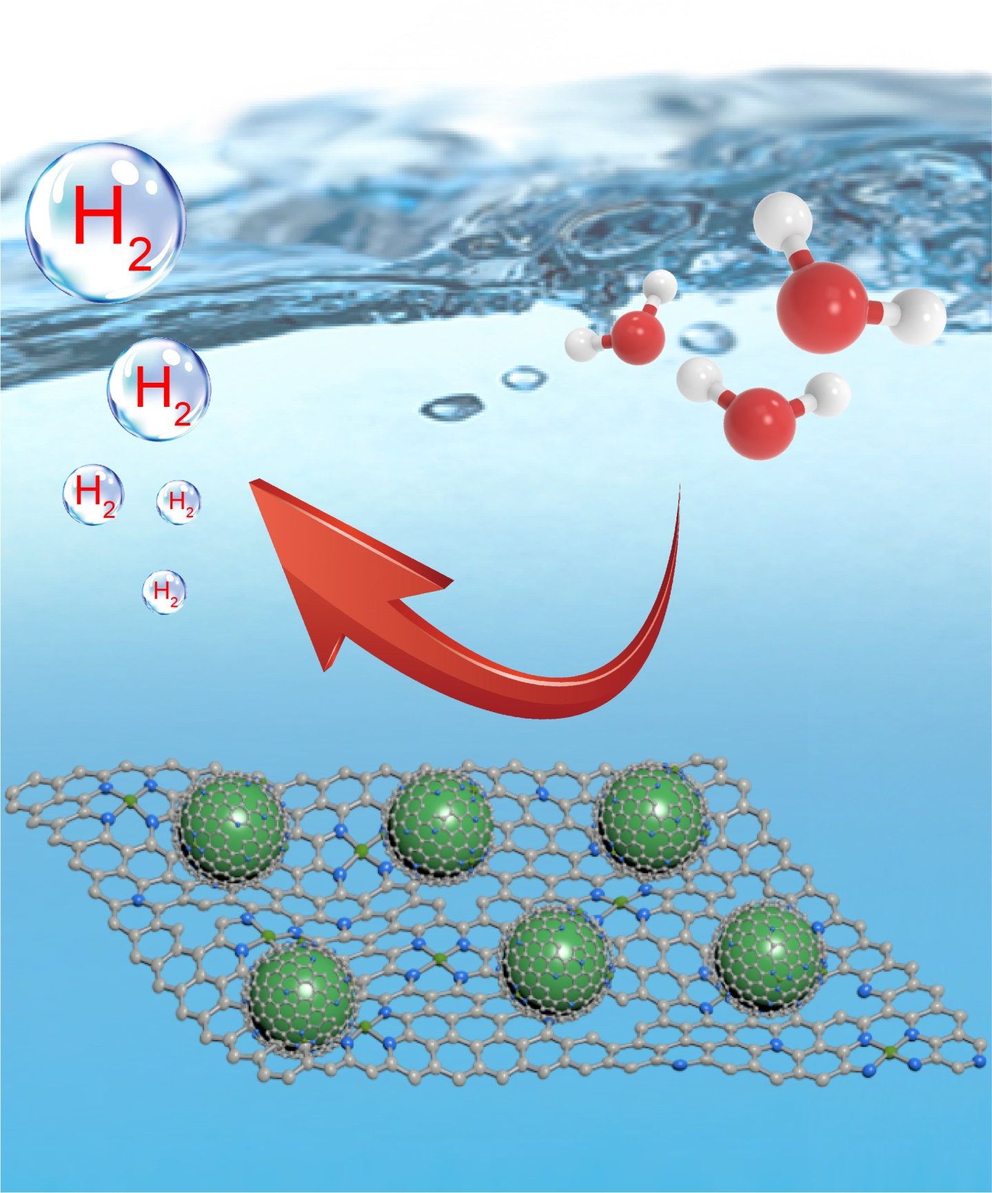
The synthetic process of the catalyst is illustrated in Scheme 1. A facile one–pot construction was developed to yield the targeting catalyst NiSe/Ni–N–C with the pyrolysis of NiCl2, 1,10–phenanthroline, selenium powder, graphitic carbon nitride (C3N4), and FCC slurry. The strong chelation of two adjacent N atoms of 1,10–phenaothroline formed stable Ni–phenanthroline complex, generating Ni single atomic sites in the form of Ni–N4 after pyrolysis [36,38]. The highly viscosity FCC slurry derived a thin carbon encapsulation layer outside NiSe NPs, preventing electrolyte corrosion and particle agglomeration during electrocatalysis. In addition, its aromatic–rich nature gives rise to a high degree of graphitization after pyrolysis, which not only affords excellent protection of active species, but also is reported to increase the loading of single atomic sites [39]. C3N4 served as both a self–sacrificing template for pore generation and a N doping reagent with the decomposed N–rich gases. Control samples NiSe/N–C, Ni–N–C, and NiSe were also synthesized with similar conditions.
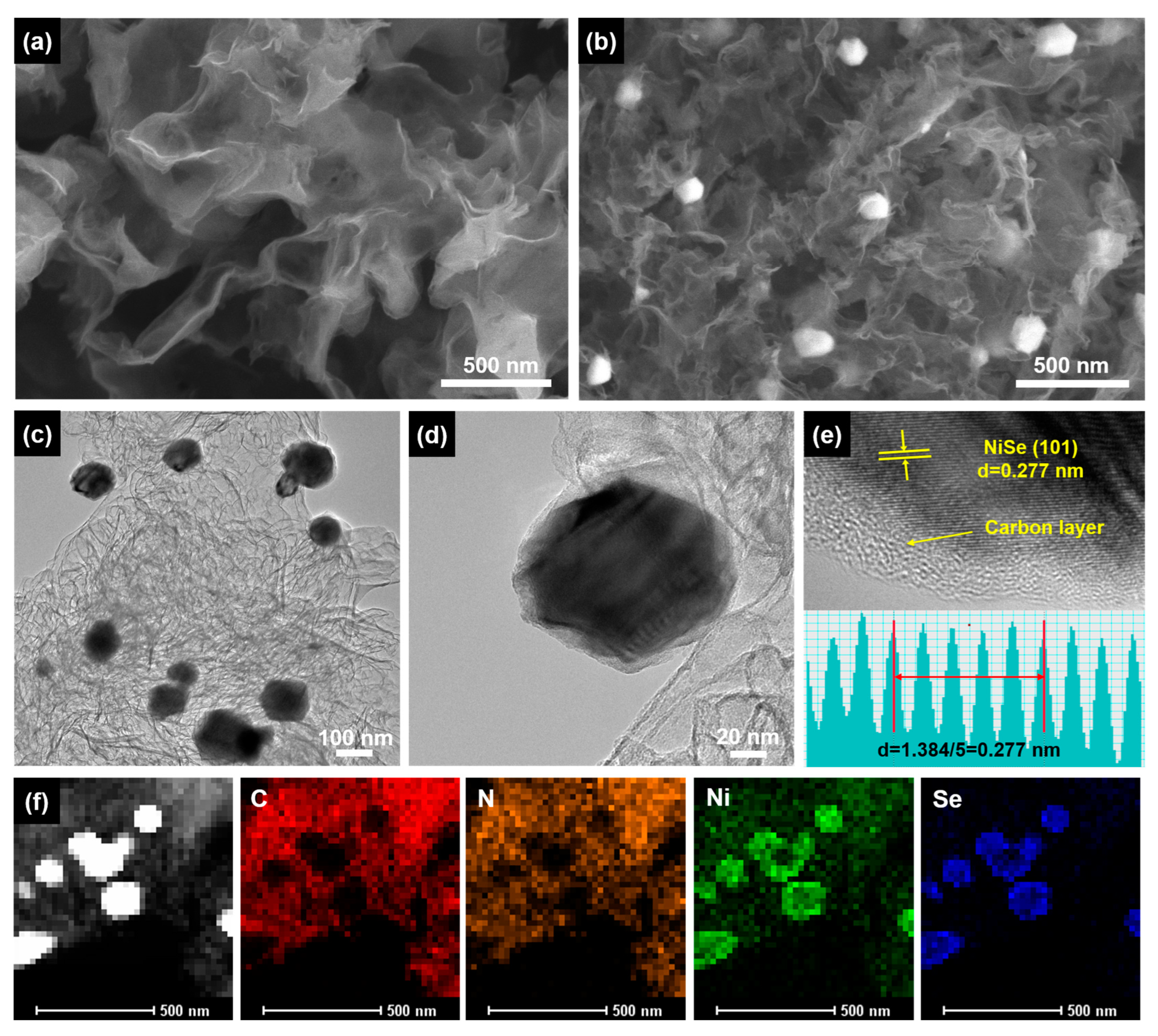
The morphologies of materials were first characterized by scanning electron microscopy (SEM) and transmission electron microscopy (TEM). Typical wrinkled carbon thin layers were observed for Ni–N–C without noticeable NPs after acid leaching (Figure 1a), indicating homogeneous distribution of single atomic sites. As for NiSe/Ni–N–C and NiSe/N–C, uniform NiSe NPs were located on the carbon matrix with even distribution (Figure 1b and Figure S1). High–resolution TEM images further revealed the average diameter of ~100 nm of anchored NPs without aggregation (Figure 1c). In comparison, significant aggregation and particle enlargement was observed at elevated pyrolysis temperatures (Figure S2). In addition, a thin layer of carbon shell coated the outside of the NiSe with a thickness of ~3 nm (Figure 1d), ascribable to the effective enwrapping of FCC slurry during pyrolysis. Lattice fringe with d spacing of 0.277 nm matched the NiSe (101) crystal plane well (Figure 1e). Energy dispersive X–ray spectroscopy (EDS) elemental mapping demonstrated the even distribution of C and N signals in the carbon backbone, confirming the successful doping of N heteroatoms (Figure 1f). Ni and Se signals corresponded to the morphology of NiSe NPs. Moreover, additional Ni was also observed on the carbon backbone, suggesting the construction of atomically distributed Ni sites.
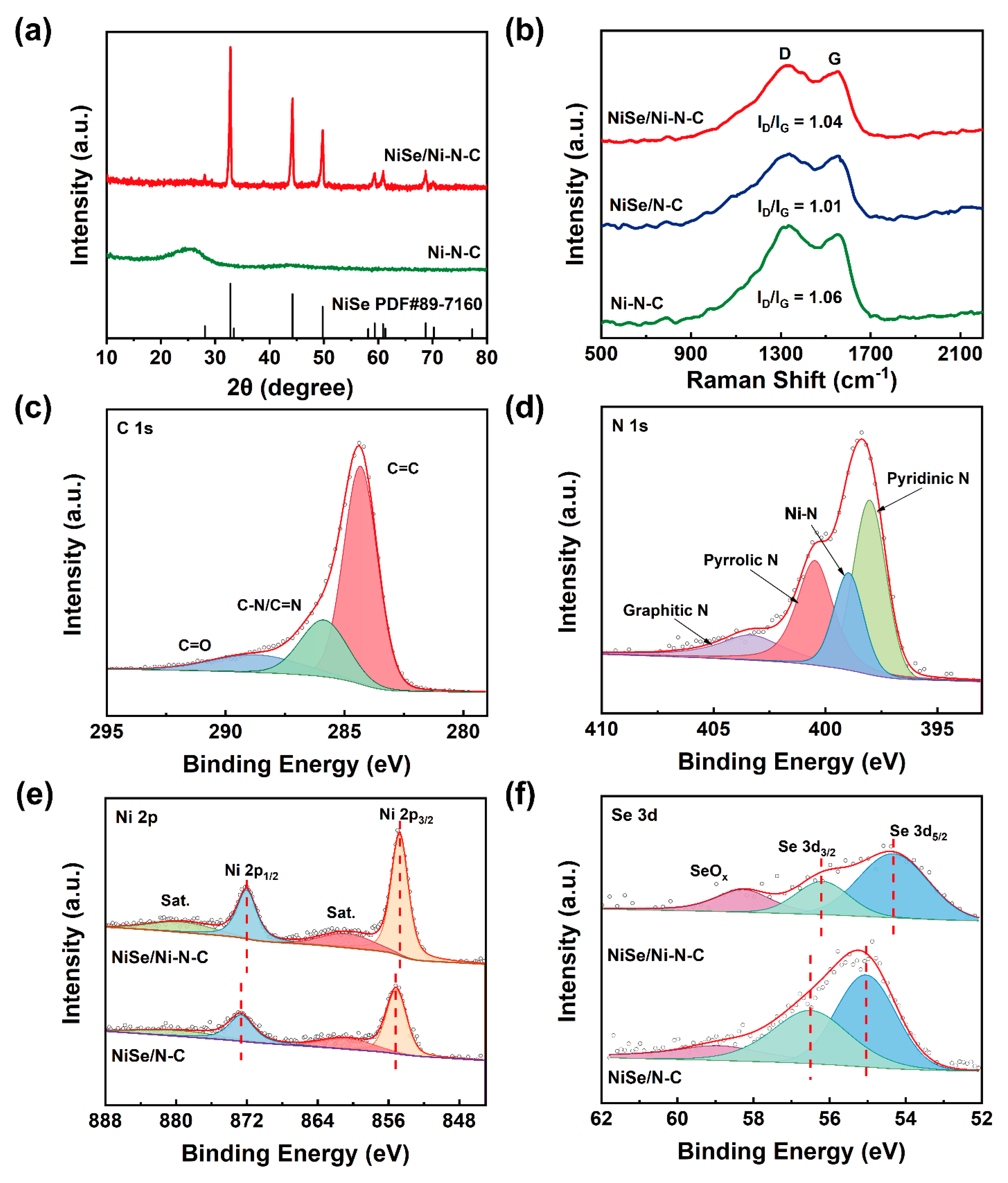
The solid–state compositions of the materials were investigated by X–ray diffraction (XRD). As shown in Figure 2a, Ni–N–C only demonstrated peaks corresponding to the carbon backbone, confirming the atomic distribution of Ni instead of Ni NPs. In comparison, with the co–pyrolysis of Se powder, distinct reflexes emerged in the diffraction pattern of NiSe/Ni–N–C, which matched standard NiSe (PDF#89–7160) very well. Raman spectroscopy was applied to mainly gain insight into the carbon component (Figure 2b). All synthesized materials showed the characteristic G band and D band, originating from the ordered graphitic carbon backbone and disordered defect structures, respectively; thus, the intensity ratio of D band over G band (ID/IG) is widely applied to evaluate the degree of defect and edge in the carbon backbone [40]. Compared to that of NiSe/N–C (1.01), ID/IG of Ni–N–C and NiSe/Ni–N–C increased to 1.06 and 1.04, respectively, indicating that the introduction of single atomic sites improved the defect level as well as the exposure of active sites on the doped carbon framework. This result was also verified by the N2 uptake test. All three materials showed typical type–IV isotherms, indicating the existence of hierarchical porous structures with microporosity and mesoporosity [41]. NiSe/Ni–N–C and Ni–N–C demonstrated larger surface areas than that of NiSe/N–C (Figure S4). The hierarchical porous structure with the existence of both micropores and mesopores facilitated the ion diffusion and mass transfer. Pyrolytic temperatures indeed played an important role in determining the properties of the materials. As shown in Figure S3, with the pyrolysis temperature increased from 700 °C to 800 °C, the ID/IG value dropped significantly from 1.09 to 1.04. The large ID/IG of NiSe/Ni–N–C–700 implied a low degree of graphitization with relatively high defect level and high impedance. The further increase of pyrolytic temperature from 800 °C to 900 °C did not yield a significant decrease of the ID/IG value (1.04 to 1.03), indicating complete graphitization at a pyrolysis temperature of 800 °C.
To further study the chemical composition, X–ray photoelectron spectroscopy (XPS) was carried out to investigate the electronic interaction as well as the charge transfer between active species. As shown in Figure S5, C, N, O, Ni, Se signals were observed in the spectrum of NiSe/Ni–N–C (Table S1). The deconvolution of C 1s profiles revealed the nature of N–doped carbon backbones (Figure 2c). The N 1s peak also demonstrated the characteristic corresponding peaks of graphitic N, pyrrolic N, and pyridinic N (Figure 2d). More importantly, an additional peak was found at 398.9 eV, which could be assigned to the Ni–N configuration, confirming the construction of Ni–N–C single atomic sites in carbon backbones [42]. The Ni 2p profile was deconvoluted into 4 peaks, corresponding to the Ni 2p3/2, satellite peak of Ni 2p3/2, Ni 2p1/2, and the satellite peak of Ni 2p1/2 with increasing binding energy (Figure 2e). Compared to the spectrum of the control sample NiSe/N–C, all peaks of Ni shifted towards lower binding energy in NiSe/Ni–N–C. A similar trend was also found for the Se 3d profiles (Figure 2f). These results suggested the weakened Ni–Se bond strength resulted from the strong interactions between NiSe NPs and a single atomic Ni [20,43,44]. We attributed this to the electron transfer from NiSe NPs to the Ni–N–C backbone, leading to the balanced electron density between active sites and thus dramatically improved catalytic activity.
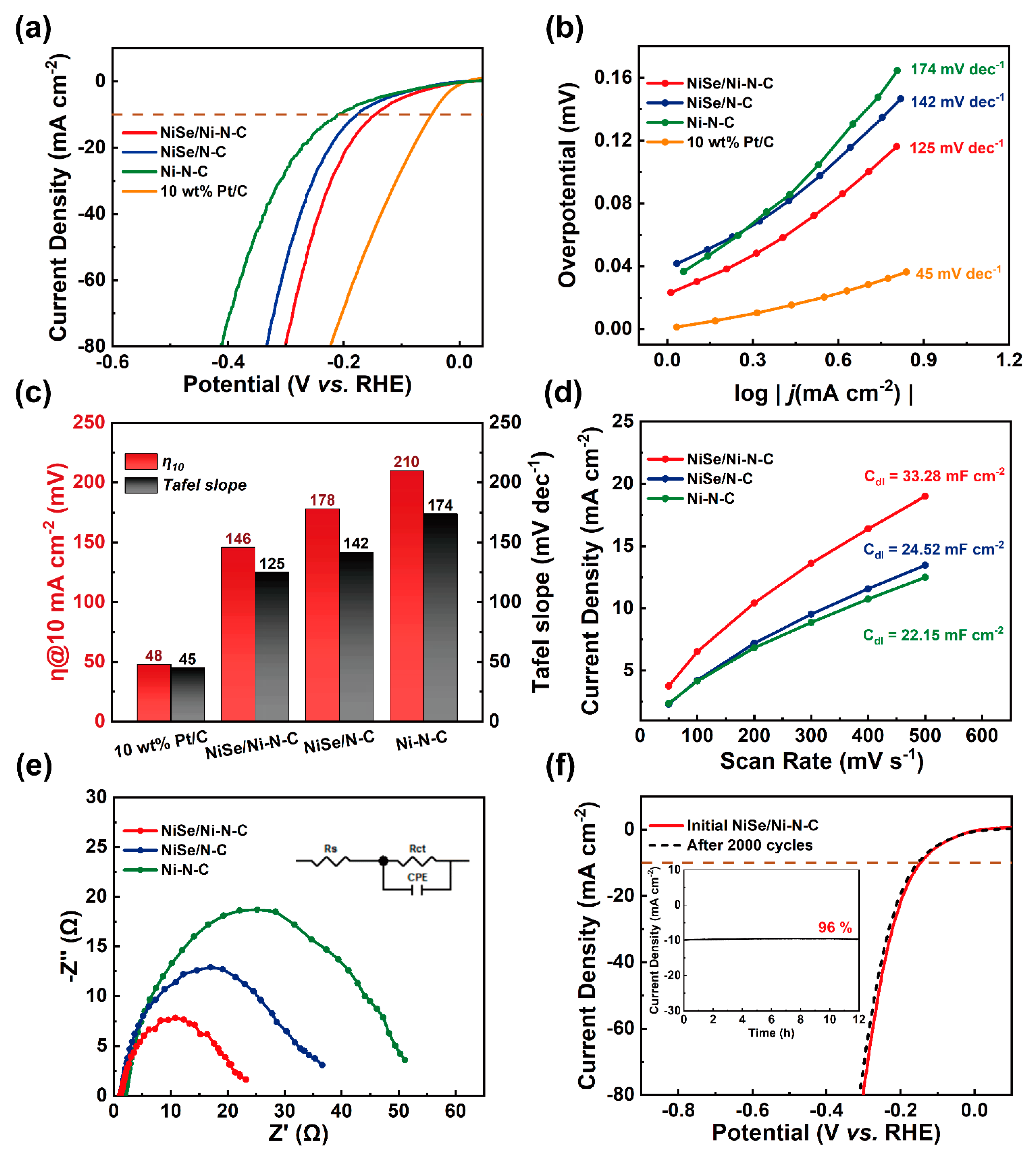
The HER performance of the obtained NiSe/Ni–N–C electrocatalyst was thoroughly evaluated with a standard three–electrode setup in 1.0 M KOH electrolyte. In comparison, NiSe/N–C, Ni–N–C, and commercially available 10% Pt/C were also tested under the same condition as the control samples. As shown in the linear sweep voltammetry (LSV) curve (Figure 3a), NiSe/Ni–N–C showed a lower overpotential of 146 mV than that of NiSe/N–C (178 mV) and Ni–N–C (210 mV) to reach a current density of 10 mA cm−2 (η10), demonstrating the superiority of the synergistic effect between NiSe NPs and Ni single atom sites. The Tafel slope derived from the LSV curves also showed a similar trend, as illustrated in Figure 3b,c, indicating that hydrogen generation increased more rapidly with increasing bias for NiSe/Ni–N–C. The LSV curves and corresponding Tafel plots of the samples during the synthesis optimization were also demonstrated in SI. In terms of pyrolytic temperatures (Figure S6a,b), pyrolysis at a lower temperature of 700 °C resulted in inferior conductivity, while NiSe nanoparticles tended to aggregate at the high pyrolytic temperature of 900 °C. Therefore, the optimized pyrolyzing temperature was determined to be 800 °C in order to realize the highest catalytic activity. The ratio of FCC slurry/Ni salt also played an important role in determining electrocatalytic performance. A certain amount of FCC slurry was able to stabilize the optimized quantity of NiSe NPs. Insufficient Ni salt of 1.0 mmol led to scarce NPs with a very thick carbon shell, while an excessive amount of NiSe tended to aggregate into large particles with limited slurry enwrapping (Figure S6c,d). Cyclic voltammetry (CV) was further investigated at various scan rates to evaluate the double–layer capacitance (Cdl) (Figure S7), which is in direct proportion to the ECSA [45,46,47]. NiSe/Ni–N–C exhibited the highest Cdl of 33.28 mF cm−2 among all the synthesized materials (Figure 3d). The corresponding dramatically higher ECSA of NiSe/Ni–N–C was ascribed to the synergy of both the high intrinsic catalytic activity and the large surface area of the Ni–N–C porous carbon backbone. In addition, NiSe/Ni–N–C demonstrated a small charge transfer resistance in electrochemical impedance spectroscopy (EIS) with the compositing and enwrapping of graphitic carbon framework (Figure 3e), thus ensuring fast electron transport and utilization. Long–term durability during electrocatalytic cycles is also a critical merit to evaluate the electrocatalyst. As shown in Figure 3f, no significant alteration was observed in the LSV curve of NiSe/Ni–N–C after 2000 CV cycles. Moreover, over 96% of the initial current density was retained after 12 h of continuous electrocatalysis in the chronoamperometry test. In addition, no obvious morphology change was observed for NiSe/Ni–N–C after continuous electrocatalysis with no nanoparticle aggregation or falling off. Thus, excellent stability was achieved in NiSe/Ni–N–C, ascribable to the effective protection from the carbon layer enwrapping. Overall, highly efficient HER activity was achieved for NiSe/Ni–N–C with excellent long–term stability. NiSe/Ni–N–C showed comparable or superior HER electrocatalytic performance compared to the other recently reported TMSes/carbon compositing materials, as summarized in Table S2.
3. Experimental Section
3.1. Materials
FCC slurry (Jinzhou refinery China; element analysis: C, 89.45%; H, 9.1%; Ni, 1.45%; V, 1.14%), NiCl2·6H2O (J&K Scientific, Beijing, China), selenium powder (Se, J&K Scientific, Beijing, China), 1, 10–phenanthroline (C₁₂H₈N₂, Sigma–Aldrich, Shanghai, China), Urea (CH4N2O, Macklin, Shanghai, China), potassium hydroxide (KOH, Macklin, Shanghai, China), Nafion solution (Aladdin, Shanghai, China), and 10 wt % platinum on carbon (Aladdin, Shanghai, China). All reagents were used as received.
3.2. Synthesis of NiSe/Ni–N–C
In a typical synthesis process, 20 g of urea was first put into the covered crucible and then annealed in an air atmosphere at 550 °C in the muffle furnace for 4 h with a 2.3 °C min−1 ramp rate. After cooling to room temperature, the C3N4 template was obtained after being pulverized. The composite of C3N4@FCC slurry was then synthesized via the condition reported in the literature [36], with the thin layer of FCC slurry enwrapping the C3N4 template. A mixture of C3N4@FCC slurry (0.600 g) and NiCl2·6H2O (0.119 g, 0.5 mmol) was dispersed in 100 mL of ethanol and sonicated for 30 min to achieve a homogeneous suspension A1. Another mixture of 1, 10–phenanthroline (0.360 g, 2 mmol) and NiCl2·6H2O (0.238 g, 1.0 mmol) was dissolved in 100 mL ethanol/H2O mixed solvent (9:1) to achieve an orange solution A2. Subsequently, A1 and A2 were combined and stirred for 6 h, before the solvent was removed by rotary evaporation. The solid was pulverized and mixed with Se powder (0.130 g, 1.65 mmol). Then the mixture was heated up to 800 °C with 5 °C min−1 and maintained for 2 h with an Ar flow rate of 100 mL min−1 to achieve NiSe/Ni–N–C. The excessive Se evaporated out with the gas flow. A comprehensive synthesis optimization was also conducted. NiSe/Ni–N–C@700 and NiSe/Ni–N–C@900 were synthesized at different pyrolysis temperatures of 700 and 900 °C, respectively. Materials with different amounts of NiCl2·6H2O (0 mmol, 0.5 mmol, 1 mmol) in A1 were also synthesized to achieve different ratios of NiSe to Ni single atom sites.
3.3. Synthesis of NiSe/N–C
The control material NiSe/N–C was synthesized with the same procedure by replacing 1, 10–phenanthroline with triphenylmethane (0.488 g, 2 mmol) in A2 to suppress the formation of single atom sites.
3.4. Synthesis of Ni–N–C
A2 solution was prepared with the same procedure. The as–synthesized C3N4@FCC was directly added into A2 and stirred for 6 h before the solvent was removed. The obtained solid was heated up to 800 °C with 5 °C min−1 and maintained for 2 h with an Ar flow rate of 100 mL min−1. Then, the powder was leached in 1.0 M H2SO4 for 6 h to completely remove the Ni nanoparticles. Finally, it was dried in vacuo to yield Ni–N–C.
3.5. Materials Characterizations
The morphologies of samples were studied by scanning electron microscopy (SEM, Quanta 200F, FEI company, Hillsboro, USA). Transmission electron microscopy (TEM) and energy dispersive X–ray spectroscopy (EDS) were collected on Tecnai G2 F20 (FEI company, Hillsboro, USA). The X–ray diffraction (XRD) patterns were characterized on Bruker D8 Advance with Cu Kα radiation. Raman spectra were collected by a Raman microscope (532 nm, XploRA, Horiba–Jobin Yvon, Paris, France). X–ray photoelectron spectroscopy (XPS, K-Alpha, Thermo Fisher Scientific, Waltham, USA) was characterized with Kα radiation. The N2 adsorption isotherms were collected on Micromeritics ASAP 2020.
3.6. Electrochemical Measurements
The HER performance was evaluated with a standard three–electrode system on an electrochemical workstation (CHI 760E). Working electrode: A mixture of 10 mg powder samples, 200 μL water, 360 μL ethanol, and 40 μL Nafion was ultrasonicated for 1 h, then 30 μL of dispersion was dropped on a piece of carbon cloth (1 cm × 0.5 cm) and dried at 60 °C for 1 h; Counter electrode: graphite rod; Reference electrode: Hg/HgO; Electrolyte: 1.0 M KOH.
Linear sweep voltammetry (LSV) of HER was measured from 0.3 V to −0.5 V vs. reversible hydrogen electrode (RHE). Cyclic voltammogram (CV) was collected between 0.425 V and 0.625 V vs. RHE, and the scan rates varied from 50 mV s−1 to 500 mV s−1. Electrochemical impedance spectroscopy (EIS) was tested at a constant bias of −0.15 V vs. RHE within the range of 10−1 Hz to 105 Hz. The stabilities of the prepared catalysts were evaluated by the chronopotentiometry tests at the corresponding potentials to drive an initial current density of 10 mA cm−2.
4. Conclusions
A composite electrocatalyst NiSe/Ni–N–C was successfully designed and synthesized via a facile one–pot pyrolysis of cost–effective precursors. The structure featured the single Ni atom doped carbon and the enwrapped NiSe NPs. The detailed characterizations revealed the apparent charge transfer at the NiSe and Ni–N–C interface, which balanced the charge density on both active sites and enhanced the electrocatalytic hydrogen production. NiSe/Ni–N–C demonstrated superior HER activities, requiring small overpotentials of 146 mV to drive a current density of 10 mA cm−2 in 1.0 M KOH. Moreover, with the deliberate interfacial engineering and carbon encapsulation, both high catalytic activity and remarkable durability were achieved for NiSe/Ni–N–C during long–term HER electrocatalysis. We envision this work provides an effective yet facile strategy to construct novel TMSe–based electrocatalysts for hydrogen evolution.
Supplementary Materials
The supporting characterization information can be downloaded at: https://www.mdpi.com/article/10.3390/catal12121525/s1. Figure S1. SEM image of NiSe/N-C.; Figure S2. SEM images of (a) NiSe/Ni-N-C@700 and (b) NiSe/Ni-N-C@900.; Figure S3. Raman spectra of NiSe/Ni-N-C pyrolyzed at 700 °C, 800 °C, and 900 °C.; Figure S4. (a) N2 adsorption isotherms at 77 K and (b) pore size distributions of NiSe/Ni-N-C.; Figure S5. Survey XPS spectrum of NiSe/Ni-N-C.; Table S1. XPS elemental analysis of NiSe/Ni-N-C.; Figure S6. (a) HER LSV curves and (b) Tafel plots of NiSe/Ni-N-C pyrolyzed at 700 °C, 800 °C, and 900 °C in 1.0 M KOH. (c) HER LSV curves and (d) Tafel plots of NiSe/Ni-N-C with the addition of 1.0 mmol, 1.5 mmol, and 2.0 mmol NiCl2 in 1.0 M KOH.; Figure S7. CV spectra of (a) NiSe/Ni-N-C, (b) Ni-N-C, and (c) NiSe/N-C with various scan rates (50–500 mV s−1) in 1.0 M KOH.; Figure S8. SEM image of NiSe/Ni-N-C after 2000 catalytic CV cycles.; Table S2. Summary of HER performances of NiSe/Ni-N-C and other reported TMSes electrocatalysts in 1.0 M KOH.
Author Contributions
S.C.: Writing—review & editing, Formal analysis, Investigation, Conceptualization. N.T.: Writing–original draft, Formal analysis, Investigation. F.Y.: Writing review & editing, Supervision. Y.Y.: Investigation. Y.L.: Writing review & editing, Supervision. S.C. and N.T. contributed equally to this work. All authors have read and agreed to the published version of the manuscript.
Funding
This work was funded by the National Natural Science Foundation of China, grant number No. 22108301, 21776302, and 22178384, and the China Postdoctoral Science Foundation, grant number No. 2021M703577.
Data Availability Statement
All the relevant data used in this study have been provided in the form of figures and tables in the published article, and all data provided in the present manuscript are available to whom it may concern.
Conflicts of Interest
The authors declare no conflict of interest.
References
- Tee, S.Y.; Win, K.Y.; Teo, W.S.; Koh, L.D.; Liu, S.; Teng, C.P.; Han, M.Y. Recent Progress in Energy–Driven Water Splitting. Adv. Sci. 2017, 4, 1600337. [Google Scholar] [CrossRef] [PubMed] [Green Version]
- Tian, X.; Zhao, P.; Sheng, W. Hydrogen Evolution and Oxidation: Mechanistic Studies and Material Advances. Adv. Mater. 2019, 31, 1808066. [Google Scholar] [CrossRef] [PubMed]
- Zhu, J.; Hu, L.; Zhao, P.; Lee, L.Y.S.; Wong, K.Y. Recent Advances in Electrocatalytic Hydrogen Evolution Using Nanoparticles. Chem. Rev. 2020, 120, 851–918. [Google Scholar] [CrossRef]
- Li, L.; Wang, P.; Shao, Q.; Huang, X. Metallic Nanostructures with Low Dimensionality for Electrochemical Water Splitting. Chem. Soc. Rev. 2020, 49, 3072–3106. [Google Scholar] [CrossRef]
- Li, Y.; Wang, H.; Priest, C.; Li, S.; Xu, P.; Wu, G. Advanced Electrocatalysis for Energy and Environmental Sustainability Via Water and Nitrogen Reactions. Adv. Mater. 2021, 33, e2000381. [Google Scholar] [CrossRef]
- Xiao, Z.R.; Wu, C.; Wang, L.; Xu, J.S.; Zheng, Q.C.; Pan, L.; Zou, J.J.; Zhang, X.W.; Li, G.Z. Boosting Hydrogen Production from Steam Reforming of Ethanol on Nickel by Lanthanum Doped Ceria. Appl. Catal. B Environ. 2021, 286, 119884. [Google Scholar] [CrossRef]
- Wei, C.; Rao, R.R.; Peng, J.; Huang, B.; Stephens, I.E.L.; Risch, M.; Xu, Z.J.; Shao-Horn, Y. Recommended Practices and Benchmark Activity for Hydrogen and Oxygen Electrocatalysis in Water Splitting and Fuel Cells. Adv. Mater. 2019, 31, e1806296. [Google Scholar] [CrossRef]
- Zhao, D.; Zhuang, Z.; Cao, X.; Zhang, C.; Peng, Q.; Chen, C.; Li, Y. Atomic Site Electrocatalysts for Water Splitting, Oxygen Reduction and Selective Oxidation. Chem. Soc. Rev. 2020, 49, 2215–2264. [Google Scholar] [CrossRef]
- Sun, H.; Xu, X.; Kim, H.; Jung, W.; Zhou, W.; Shao, Z. Electrochemical Water Splitting: Bridging the Gaps between Fundamental Research and Industrial Applications. Energy Environ. Mater. 2022, e12441. [Google Scholar] [CrossRef]
- Anantharaj, S.; Noda, S.; Jothi, V.R.; Yi, S.; Driess, M.; Menezes, P.W. Strategies and Perspectives to Catch the Missing Pieces in Energy–Efficient Hydrogen Evolution Reaction in Alkaline Media. Angew. Chem. Int. Ed. 2021, 60, 18981–19006. [Google Scholar] [CrossRef] [PubMed]
- Liu, D.; Li, X.; Chen, S.; Yan, H.; Wang, C.; Wu, C.; Haleem, Y.A.; Duan, S.; Lu, J.; Ge, B.; et al. Atomically Dispersed Platinum Supported on Curved Carbon Supports for Efficient Electrocatalytic Hydrogen Evolution. Nat. Energy 2019, 4, 512–518. [Google Scholar] [CrossRef]
- Chong, L.; Wen, J.; Kubal, J.; Sen, F.G.; Zou, J.; Greeley, J.; Chan, M.; Barkholtz, H.; Ding, W.; Liu, D.J. Ultralow–Loading Platinum–Cobalt Fuel Cell Catalysts Derived from Imidazolate Frameworks. Science 2018, 362, 1276–1281. [Google Scholar] [CrossRef] [PubMed]
- Mahmood, J.; Li, F.; Jung, S.M.; Okyay, M.S.; Ahmad, I.; Kim, S.J.; Park, N.; Jeong, H.Y.; Baek, J.B. An Efficient and Ph–Universal Ruthenium–Based Catalyst for the Hydrogen Evolution Reaction. Nat. Nanotechnol. 2017, 12, 441–446. [Google Scholar] [CrossRef] [PubMed]
- Peng, X.; Yan, Y.J.; Jin, X.; Huang, C.; Jin, W.H.; Gao, B.; Chu, P.K. Recent Advance and Prospectives of Electrocatalysts Based on Transition Metal Selenides for Efficient Water Splitting. Nano Energy 2020, 78, 105234. [Google Scholar] [CrossRef]
- Lu, H.; Zhang, Y.; Huang, Y.; Zhang, C.; Liu, T. Reaction Packaging Cose2 Nanoparticles in N–Doped Carbon Polyhedra with Bifunctionality for Overall Water Splitting. ACS Appl. Mater. Interfaces 2019, 11, 3372–3381. [Google Scholar] [CrossRef] [PubMed]
- Sun, H.; Song, S.; Xu, X.; Dai, J.; Yu, J.; Zhou, W.; Shao, Z.; Jung, W. Recent Progress on Structurally Ordered Materials for Electrocatalysis. Adv. Energy Mater. 2021, 11, 2101937. [Google Scholar] [CrossRef]
- Xia, X.; Wang, L.; Sui, N.; Colvin, V.L.; Yu, W.W. Recent Progress in Transition Metal Selenide Electrocatalysts for Water Splitting. Nanoscale 2020, 12, 12249–12262. [Google Scholar] [CrossRef]
- Chen, P.; Xu, K.; Tao, S.; Zhou, T.; Tong, Y.; Ding, H.; Zhang, L.; Chu, W.; Wu, C.; Xie, Y. Phase–Transformation Engineering in Cobalt Diselenide Realizing Enhanced Catalytic Activity for Hydrogen Evolution in an Alkaline Medium. Adv. Mater. 2016, 28, 7527–7532. [Google Scholar] [CrossRef]
- Lin, H.; Zhu, Q.; Shu, D.; Lin, D.; Xu, J.; Huang, X.; Shi, W.; Xi, X.; Wang, J.; Gao, L. Growth of Environmentally Stable Transition Metal Selenide Films. Nat. Mater. 2019, 18, 602–607. [Google Scholar] [CrossRef]
- Chae, S.H.; Muthurasu, A.; Kim, T.; Kim, J.S.; Khil, M.S.; Lee, M.; Kim, H.; Lee, J.Y.; Kim, H.Y. Templated Fabrication of Perfectly Aligned Metal–Organic Framework–Supported Iron–Doped Copper–Cobalt Selenide Nanostructure on Hollow Carbon Nanofibers for an Efficient Trifunctional Electrode Material. Appl. Catal. B Environ. 2021, 293, 120209. [Google Scholar] [CrossRef]
- Gao, M.; Lin, Z.; Zhuang, T.; Jiang, J.; Xu, Y.; Zheng, Y.; Yu, S. Mixed–Solution Synthesis of Sea Urchin–Like Nise Nanofiber Assemblies as Economical Pt–Free Catalysts for Electrochemical H2 Production. J. Mater. Chem. 2012, 22, 13662. [Google Scholar] [CrossRef]
- Liang, H.F.; Li, L.S.; Meng, F.; Dang, L.N.; Zhuo, J.Q.; Forticaux, A.; Wang, Z.C.; Jin, S. Porous Two–Dimensional Nanosheets Converted from Layered Double Hydroxides and Their Applications in Electrocatalytic Water Splitting. Chem. Mater. 2015, 27, 5702–5711. [Google Scholar] [CrossRef]
- Li, W.; Yu, B.; Hu, Y.; Wang, X.; Yang, D.; Chen, Y. Core–Shell Structure of Nise2 Nanoparticles@Nitrogen–Doped Graphene for Hydrogen Evolution Reaction in Both Acidic and Alkaline Media. ACS Sustain. Chem. Eng. 2019, 7, 4351–4359. [Google Scholar] [CrossRef]
- Huang, Z.D.; Yuan, S.; Zhang, T.T.; Cai, B.; Xu, B.; Lu, X.Q.; Fan, L.L.; Dai, F.N.; Sun, D.F. Selective Selenization of Mixed–Linker Ni–Mofs: Nise2@Nc Core–Shell Nano–Octahedrons with Tunable Interfacial Electronic Structure for Hydrogen Evolution Reaction. Appl. Catal. B Environ. 2020, 272, 118976. [Google Scholar] [CrossRef]
- Wang, T.; Zhang, X.; Yang, P.; Jiang, S.P. Vertically Aligned Mos2 Nanosheets on N–Doped Carbon Nanotubes with Nife Alloy for Overall Water Splitting. Inorg. Chem. Front. 2020, 7, 3578–3587. [Google Scholar] [CrossRef]
- Li, S.; Peng, S.; Huang, L.; Cui, X.; Al-Enizi, A.M.; Zheng, G. Carbon–Coated Co(3+)–Rich Cobalt Selenide Derived from Zif–67 for Efficient Electrochemical Water Oxidation. ACS Appl. Mater. Interfaces 2016, 8, 20534–20539. [Google Scholar] [CrossRef]
- Li, X.; Zhang, L.; Huang, M.R.; Wang, S.Y.; Li, X.M.; Zhu, H.W. Cobalt and Nickel Selenide Nanowalls Anchored on Graphene as Bifunctional Electrocatalysts for Overall Water Splitting. J. Mater. Chem. A 2016, 4, 14789–14795. [Google Scholar] [CrossRef]
- Cao, L.; Luo, Q.; Liu, W.; Lin, Y.; Liu, X.; Cao, Y.; Zhang, W.; Wu, Y.; Yang, J.; Yao, T.; et al. Identification of Single–Atom Active Sites in Carbon–Based Cobalt Catalysts During Electrocatalytic Hydrogen Evolution. Nat. Catal. 2018, 2, 134–141. [Google Scholar] [CrossRef]
- Jiang, H.; Gu, J.; Zheng, X.; Liu, M.; Qiu, X.; Wang, L.; Li, W.; Chen, Z.; Ji, X.; Li, J. Defect–Rich and Ultrathin N Doped Carbon Nanosheets as Advanced Trifunctional Metal–Free Electrocatalysts for the Orr, Oer and Her. Energy Environ. Sci. 2019, 12, 322–333. [Google Scholar] [CrossRef]
- Cao, X.; Zhao, L.; Wulan, B.; Tan, D.; Chen, Q.; Ma, J.; Zhang, J. Atomic Bridging Structure of Nickel–Nitrogen–Carbon for Highly Efficient Electrocatalytic Reduction of CO2. Angew. Chem. Int. Ed. 2021, 61, e202113918. [Google Scholar]
- Li, Y.; Zhang, S.L.; Cheng, W.; Chen, Y.; Luan, D.; Gao, S.; Lou, X.W.D. Loading Single–Ni Atoms on Assembled Hollow N–Rich Carbon Plates for Efficient CO2 Electroreduction. Adv. Mater. 2021, 34, e2105204. [Google Scholar] [CrossRef] [PubMed]
- Yang, Q.; Liu, H.; Yuan, P.; Jia, Y.; Zhuang, L.; Zhang, H.; Yan, X.; Liu, G.; Zhao, Y.; Liu, J.; et al. Single Carbon Vacancy Traps Atomic Platinum for Hydrogen Evolution Catalysis. J. Am. Chem. Soc. 2022, 144, 2171–2178. [Google Scholar] [CrossRef] [PubMed]
- Fan, L.; Liu, P.F.; Yan, X.; Gu, L.; Yang, Z.Z.; Yang, H.G.; Qiu, S.; Yao, X. Atomically Isolated Nickel Species Anchored on Graphitized Carbon for Efficient Hydrogen Evolution Electrocatalysis. Nat. Commun. 2016, 7, 10667. [Google Scholar] [CrossRef] [PubMed] [Green Version]
- Liu, R.; Chen, Z.; Yao, Y.; Li, Y.; Cheema, W.A.; Wang, D.; Zhu, S. Recent Advancements in G–C3n4–Based Photocatalysts for Photocatalytic CO2 Reduction: A Mini Review. RSC Adv. 2020, 10, 29408–29418. [Google Scholar] [CrossRef]
- Yuda, A.; Kumar, A. A Review of G–C3n4 Based Catalysts for Direct Methanol Fuel Cells. Int. J. Hydrogen Energy 2022, 47, 3371–3395. [Google Scholar] [CrossRef]
- Yan, X.; Che, S.; Yang, F.; Xu, Z.; Liu, H.; Li, C.; Yan, L.; Ta, N.; Sun, S.; Wei, Q.; et al. Highly Efficient Water Splitting Catalyst Composed of N,P–Doped Porous Carbon Decorated with Surface P–Enriched Ni2p Nanoparticles. ACS Appl. Mater. Interfaces 2022, 14, 20358–20367. [Google Scholar] [CrossRef]
- Che, S.; Ta, N.; Yang, F.; Yan, X.; Liu, H.; Chen, N.; Sun, S.; Wang, C.; Jiang, B.; Sun, Y.; et al. One–Pot Construction of Cose Nanoparticles Anchored on Single–Atomic–Co Doped Carbon for Ph–Universal Hydrogen Evolution. Mater. Chem. Front. 2022, 6, 3577–3588. [Google Scholar] [CrossRef]
- Xi, D.; Li, J.; Low, J.; Mao, K.; Long, R.; Li, J.; Dai, Z.; Shao, T.; Zhong, Y.; Li, Y.; et al. Limiting the Uncoordinated N Species in M–Nx Single–Atom Catalysts toward Electrocatalytic CO2 Reduction in Broad Voltage Range. Adv. Mater. 2021, 34, e2104090. [Google Scholar] [CrossRef]
- Zhao, Q.; Tan, X.; Ma, T.; Cao, F.; Xia, Z.; Liu, H.; Ning, H.; Li, Z.; Hu, H.; Wu, M. Reinforced Atomically Dispersed Fenc Catalysts Derived from Petroleum Asphalt for Oxygen Reduction Reaction. J. Colloid Interface Sci. 2021, 587, 810–819. [Google Scholar] [CrossRef]
- Che, S.; Li, C.; Wang, C.; Zaheer, W.; Ji, X.; Phillips, B.; Gurbandurdyyev, G.; Glynn, J.; Guo, Z.H.; Al-Hashimi, M.; et al. Solution–Processable Porous Graphitic Carbon from Bottom–up Synthesis and Low–Temperature Graphitization. Chem. Sci. 2021, 12, 8438–8444. [Google Scholar] [CrossRef]
- Che, S.; Pang, J.; Kalin, A.J.; Wang, C.; Ji, X.; Lee, J.; Cole, D.; Li, J.; Tu, X.; Zhang, Q.; et al. Rigid Ladder–Type Porous Polymer Networks for Entropically Favorable Gas Adsorption. ACS Mater. Lett. 2020, 2, 49–54. [Google Scholar] [CrossRef]
- Zhang, Y.; Jiao, L.; Yang, W.; Xie, C.; Jiang, H.L. Rational Fabrication of Low–Coordinate Single–Atom Ni Electrocatalysts by Mofs for Highly Selective CO2 Reduction. Angew. Chem. Int. Ed. 2021, 60, 7607–7611. [Google Scholar] [CrossRef] [PubMed]
- Zhang, Z.; Zhao, X.; Xi, S.; Zhang, L.; Chen, Z.; Zeng, Z.; Huang, M.; Yang, H.; Liu, B.; Pennycook, S.J.; et al. Atomically Dispersed Cobalt Trifunctional Electrocatalysts with Tailored Coordination Environment for Flexible Rechargeable Zn–Air Battery and Self-Driven Water Splitting. Adv. Energy Mater. 2020, 10, 2002896. [Google Scholar] [CrossRef]
- Liu, S.; Gao, M.; Liu, S.; Luo, J. Hierarchically Assembling Cobalt/Nickel Carbonate Hydroxide on Copper Nitride Nanowires for Highly Efficient Water Splitting. Appl. Catal. B Environ. 2021, 292, 120148. [Google Scholar] [CrossRef]
- Zhang, D.; Li, H.; Riaz, A.; Sharma, A.; Liang, W.; Wang, Y.; Chen, H.; Vora, K.; Yan, D.; Su, Z.; et al. Unconventional Direct Synthesis of Ni3n/Ni with N–Vacancies for Efficient and Stable Hydrogen Evolution. Energy Environ. Sci. 2022, 15, 185–195. [Google Scholar] [CrossRef]
- Song, Y.; Cheng, J.; Liu, J.; Ye, Q.; Gao, X.; Lu, J.; Cheng, Y. Modulating Electronic Structure of Cobalt Phosphide Porous Nanofiber by Ruthenium and Nickel Dual Doping for Highly–Efficiency Overall Water Splitting at High Current Density. Appl. Catal. B Environ. 2021, 298, 120488. [Google Scholar] [CrossRef]
- Liu, R.; Gong, Z.; Liu, J.; Dong, J.; Liao, J.; Liu, H.; Huang, H.; Liu, J.; Yan, M.; Huang, K.; et al. Design of Aligned Porous Carbon Films with Single–Atom Co–N–C Sites for High–Current–Density Hydrogen Generation. Adv. Mater. 2021, 33, e2103533. [Google Scholar] [CrossRef]
Scheme 1.
Graphical illustration of the one–pot synthetic procedure of NiSe/Ni–N–C.

Figure 1.
Morphology characterizations: (a) SEM images of Ni–N–C; (b) SEM images; (c–e) HR–TEM; (f) HAADF–TEM and EDS elemental mapping of NiSe/Ni–N–C.
Figure 1.
Morphology characterizations: (a) SEM images of Ni–N–C; (b) SEM images; (c–e) HR–TEM; (f) HAADF–TEM and EDS elemental mapping of NiSe/Ni–N–C.

Figure 2.
(a) XRD patterns; (b) Raman spectra; XPS profiles and deconvolutions of (c) C 1s, (d) N 1s, (e) Ni 2p, (f) Se 3d of NiSe/Ni–N–C and NiSe/N–C.
Figure 2.
(a) XRD patterns; (b) Raman spectra; XPS profiles and deconvolutions of (c) C 1s, (d) N 1s, (e) Ni 2p, (f) Se 3d of NiSe/Ni–N–C and NiSe/N–C.

Figure 3.
HER activity in 1.0 M KOH: (a), LSV polarization curves, (b) Tafel plots, (c) comparison of η10 values and Tafel slopes, (d) capacitive current density as a function of scan rates, and (e) Nyquist plots of NiSe/Ni–N–C and control samples. (f) LSV polarization curves of NiSe/Ni–N–C before and after 2000 CV cycles. Inset: chronopotentiometry test of NiSe/Ni–N–C under a constant potential of 146 mV for more than 12 h.

Publisher’s Note: MDPI stays neutral with regard to jurisdictional claims in published maps and institutional affiliations. |
© 2022 by the authors. Licensee MDPI, Basel, Switzerland. This article is an open access article distributed under the terms and conditions of the Creative Commons Attribution (CC BY) license (https://creativecommons.org/licenses/by/4.0/).
Share and Cite
MDPI and ACS Style
Che, S.; Ta, N.; Yang, F.; Yang, Y.; Li, Y. Interfacial Electronic Engineering of NiSe–Anchored Ni–N–C Composite Electrocatalyst for Efficient Hydrogen Evolution. Catalysts 2022, 12, 1525. https://doi.org/10.3390/catal12121525
AMA Style
Che S, Ta N, Yang F, Yang Y, Li Y. Interfacial Electronic Engineering of NiSe–Anchored Ni–N–C Composite Electrocatalyst for Efficient Hydrogen Evolution. Catalysts. 2022; 12(12):1525. https://doi.org/10.3390/catal12121525
Chicago/Turabian StyleChe, Sai, Na Ta, Fan Yang, Yulong Yang, and Yongfeng Li. 2022. "Interfacial Electronic Engineering of NiSe–Anchored Ni–N–C Composite Electrocatalyst for Efficient Hydrogen Evolution" Catalysts 12, no. 12: 1525. https://doi.org/10.3390/catal12121525
Note that from the first issue of 2016, this journal uses article numbers instead of page numbers. See further details here.