

Improved Bond Stress-Slip Relationships for Carbon Fibre-Reinforced Polymer-Strengthened Masonry Triplets

School of Science & Technology, City, University of London, Northampton Square, London EC1V 0HB, UK
*
Author to whom correspondence should be addressed.
Buildings 2024, 14(1), 257; https://doi.org/10.3390/buildings14010257
Submission received: 24 November 2023
/
Revised: 9 January 2024
/
Accepted: 12 January 2024
/
Published: 17 January 2024
(This article belongs to the Special Issue Fiber-Reinforced Polymers and Fiber-Reinforced Concrete in Civil Engineering)
Abstract
:Carbon fibre-reinforced polymer (CFRP) emerges as a viable solution for reinforcing unreinforced masonry (URM) walls subjected to shear loads. While masonry structures are straightforward to construct, the complexity of the construction materials, especially in terms of their mechanical properties, poses challenges for numerical studies of their structural behaviour. Walls, being fundamental components in masonry construction, play a crucial role in transferring both horizontal and vertical lateral forces. This study investigates the enhancement of masonry wall behaviour through the reinforcement of CFRP. CFRP reinforcement increases ductility and strength, reducing the risk of failure under shear conditions. Additionally, CFRP composites present a practical solution to strengthening masonry structures compared to traditional reinforcement. However, brick, mortar, and CFRP have not been thoroughly investigated. Experimental tests on the bond behaviour of different configurations of CFRP-retrofitted masonry triplets have not been performed before and are therefore presented in this paper. Triplet specimens, comprising three bricks and two mortar joints, both with and without CFRP strengthening, were subjected to bond testing. The study affirms that masonry triplets strengthened with CFRP under shear loads exhibit strength levels at least four to six times greater than those without CFRP. The experimental work was carried out with eight different CFRP configurations on triplet masonry, and each test was repeated four times. Further, the bond stress-slip relationship in the case of masonry triplets with and without CFRP was predicted with new mathematical equations based on the conducted test results. These equations were included in the commercial finite element software ANSYS and used to conduct simulations of CFRP-reinforced masonry triplets. The numerical results indicate good agreement between the finite element model and the test results. The outcome of this research improves the current knowledge on the use of CFRP to reinforce masonry walls with brick and mortar, which will contribute to the understanding of the effect of CFRP on masonry structures.
1. Introduction
According to Ehsani and Saadatmanesh [1,2,3], a significant percentage of existing buildings are made from masonry, where the mechanical properties of brickwork are more complex than other structure materials. Failure in URM structures due to in-plane or out-of-plane loads is one of the major reasons for human injury. Strengthening and repairing the existing buildings is one of the main challenges in the field of civil engineering. The strengthening and reinforcement of masonry components can be carried out based on traditional materials such as steel and concrete. Reinforced concrete (RC) jackets are a technique for strengthening masonry constructions that involves placing jackets on one or both sides of masonry walls. The steel-reinforced brick masonry consists of brick masonry with steel reinforcement or mild steel iron mesh or bars embedded in the mortar. According to Ferretti et al. [4], from the mechanical point of view, masonry is a heterogeneous, nonlinear, and anisotropic material, consisting of masonry units, mortar, and masonry unit-to-mortar interfaces. Also, masonry is characterized by its very low tensile strength, substantial strength in compression, and weak performance in bending and shear. Indeed, it is well known that masonry buildings are weak against horizontal actions. Tensile and shear bond strengths are quite low and highly variable. Thus, masonry walls fail mostly through masonry unit-to-mortar interfaces, known as planes of weakness.
Ehsani and Saadatmanesh [5] concluded that traditional methods of strengthening often add extra load to structures, making them riskier. The interface behaviour of brick and mortar in masonry composites has been investigated by Mohammadipour [6]. Pavan and Nanjunda [7] studied the effectiveness of FRP composites in improving the brick–mortar interface. They studied two types of masonry assemblies to investigate the interfacial behaviour of brick–mortar joints in masonry triplets. The samples were bonded with glass and carbon FRP in strip form. According to their experimental tests, in the case of masonry triplets bonded with GFRP and CFRP composites, the percentage increases in shear strength covering the full triplet face and strips were approximately 165% and 185%, respectively. Many researchers have studied the behaviour of FRP-strengthened triplet masonry with one or two FRP configurations. Reinforcing masonry walls with fibre-reinforced polymers (FRP) was considered to increase strength and ductility and thus reduce the risk of failure under severe loading conditions. Fibre-reinforced polymer (FRP) composites may provide technically and economically viable solutions, as stated by Tumialan et al. [8,9,10,11]. El Malyh et al. [12] studied the effect of CFRP wrap on the strength and stiffness of URM walls. An experimental programme was set up to investigate the in-plane behaviour of the standardized specimens following ASTM E-519-02 [13]. The test included testing clay brick panels of 1200 × 1200 × 100 mm fixed at the ends. In all cases, the reinforced panels improved the shear strength and deformations of the samples before failure. According to their study, the retrofitting system restrains the URM wall from shear failure and shear sliding. It enhanced their strength by up to 319%, and all CFRP configurations significantly improved the load-bearing capacity of the specimens by 2.5 to 4.2 times. Babatunde [14] studied glass and carbon fibre-reinforced polymers (GFRP and CFRP) to reinforce masonry walls. The experimental tests showed that externally bonded FRP systems improve flexural strength and ductility and increase strain capacity and stability. Near-surface-mounted FRP systems improve out-of-plane bending and lateral resistance. The FRP strip strengthening technique for in-plane loading improves strength, ductility, and lateral load resistance by up to four times that of the unreinforced walls, and for out-of-plane loading, it minimizes displacement. According to Hamrat et al. [15], the restoration and reinforcement of cracked structural members with externally bonded (CFRP) sheets has become one of the greatest challenges confronting civil engineers. CFRP composites bonded to damaged structural members can significantly improve their mechanical behaviour and reduce crack propagation by increasing the load capacity. Luccioni and Rougier [16,17], indicated that CFRP improves the strength of bed joints under compression and increases ductility and failure mode. Depending on the dimensions and orientation, retrofitting with CFRP increases ductility under in-plane shear, prevents the joints from sliding, and increases the ultimate strength. According to Hernoune et al. [18], in order to extend the life of masonry structures, strengthening or repairing by employing new techniques has been developed. Many of these strengthening techniques, including the use of fibre-reinforced polymer (FRP) composites, have aided in reinforcing masonry structures. These composites are manufactured with different features depending on the fibre material type, such as carbon fibre (CFRP), glass (GFRP), and aramid (AFRP). FRP strips offer the possibility of application by glueing on externally bonded elements using the near-surface-mounted (NSM) technique. Hamid et al. [19] studied the shear behaviour of FRP-glued masonry composed of hollow concrete blocks. The study demonstrated the effectiveness of FRP in preventing the brittle failure modes exhibited by URM and improving the shear strength and deformation ability of masonry.
Saingam et al. [20] studied the flexural capacity of cement–clay interlocking (CCI) brick walls using ferrocement jackets with an expanded wire mesh. Their experimental results showed that the reinforced walls exhibited improved peak load capacity, notably in dual-sided reinforcement cases. With plastering on both sides and supplemented with anchors, an improvement of up to 221% in flexural capacity was obtained. The strengthened walls significantly improved CCI brick wall performance, increasing peak capacity by up to 46%. Specifically, one-sided strengthening enhanced peak capacity by 28.60%, while two-sided strengthening boosted it by 64.29%. Joyklad and Hussain [21] indicated that the diagonal compression capacity of cement–clay interlocking (CCI) brick walls was significantly improved by the addition of grout in the openings of CCI bricks. An increase of up to 418% in the diagonal compressive capacity was observed by the addition of grout, whereas the same improvement jumped to 567% after the addition of steel bars. Rashid et al. [22] investigated the bearing capacity performance of Kenaf fibre geotextile laid on inside the sand layer. A rigid footing was used to replicate a strip footing during the loading test, and sand was prepared based on 50% of the relative density in a rigid testing chamber for ground model preparation. In order to treat the soil, Kenaf fibre geotextile was laid at four different locations, which are on the soil surface and underneath the ground model surface at 50, 75, and 100 mm deep. It was found that the use of the Kenaf fibre geotextile has improved the bearing capacity of the sandy soil up to 414.9% as compared to untreated soil. Saidi et al. [23] developed an empirical model for predicting the bond strength between natural fibre-reinforced polymer (NFRP) sheets and concrete. The NFRP was produced from fabric using four different types of fibres, including jute, silk, and pineapple, as well as dense and non-dense abaca fibres. Moreover, three different types of bonding adhesives were applied to bond the NFRP composite produced from abaca fibre to the concrete surface, and these include standard epoxy resin, polyester resin, and thixotropic epoxy resin. The size of the specimens was 100 mm × 100 mm × 300 mm, with a single longitudinal reinforcing bar with a diameter of 10 mm in the centre of its cross-section and a pre-existing crack in the middle of its length on two opposite sides. NFRP composites with a size of 50 mm × 240 mm were subsequently applied to both sides containing a crack. They discovered that the fibre type used in producing NFRP affected the bonding strength between NFRP and concrete. Abaca was found to have the highest contribution, followed by jute and silk, while pineapple fibres have the smallest contribution. The use of two and three layers of fabrics enhanced the initial stiffness by 143–276% and 257–691%, respectively; bond strength by 118–350% and 312–400%, respectively; and toughness by 136–440% and 199–667%, respectively, depending on the fabric and bonding adhesive types. The behaviour analysis of strengthened concrete beams with natural fibre-reinforced polymer (NFRP) based on abaca fibre using the finite element method was investigated by Amalia et al. [24]. Based on the results of the study, the results of numerical analysis using ATENA V534 showed a lower maximum load value, higher stiffness, and lower deflection at maximum load compared to experimental results on all reinforced concrete beams analysed in their study. Based on the results of numerical analysis using ATENA V534 software (ATENA 3D Version 5.4.1) and experimental results in the laboratory, NFRP reinforcement with a vertical configuration was recommended because it can increase the maximum load, which is higher than the diagonal configuration.
Enhancing the resistance of masonry structures significantly relies on the integrity of the bond between the masonry unit and the mortar, impacting their shearing strength. Consequently, prioritizing improvements in the shear performance of these buildings becomes crucial. Typically, mortar joints constitute the weakest link within masonry, and their nonlinear response to tension and shear greatly influences the overall behaviour of the composite structure. Accurately predicting the load-bearing capacity of unreinforced masonry buildings when subjected to combined compression and shear demands a precise understanding of masonry strength and its broader response to bond stresses. Previous studies attempted to evaluate the bond stress-slip relationship of the brick–mortar interface for un-strengthened specimens. These relationships in the presence of FRP strengthening have not been fully evaluated yet. In this study, an extensive set of experiments was conducted for two main categories: 1—unreinforced masonry triplet specimens and 2—masonry triplets reinforced with carbon fibre-reinforced polymer (CFRP). The purpose of the tests is to evaluate the bond stress-slip behaviour of FRP-strengthened masonry triplets. These triplets were specifically built using mortar M4 and subjected to testing with varying configurations of CFRP. Based on the test results, mathematical models of the bond stress-slip were developed for each configuration and coded into a finite element (FE) platform. This FE model looked into bond-slip and normal separation occurring at the brick–mortar interface using a detailed micro-modelling approach. Furthermore, the numerical analysis was able to simulate the initiation and propagation of cracks within the mortar layer. Subsequently, the outcomes of these numerical simulations were compared with the results obtained from the experiments. A few researchers have studied the behaviour of FRP-strengthened triplet masonry with one or two FRP configurations. In this paper, the strength and bond stress-slip relationship of URM for eight different CFRP configurations were studied to fill this gap and provide accurate constitutive models for all practical cases.
The present research objectives are as follows:
- To study the effect of different CFRP configurations on unreinforced triplet masonry (URTM) and investigate the behaviour of triplet specimens when failure occurs through the brick–mortar interface.
- To evaluate experimentally the bond behaviour between brick and mortar in the presence of different configurations of CFRP, which has not been previously studied.
- To develop mathematical equations for the bond stress-slip relationships identified in (2) to be used for accurate numerical simulation of FRP-strengthened masonry specimens.
2. Experimental Design, Material, and Methods
Small-scale specimens were used in an experimental test. This information was used to calibrate formulas for the design and computation of masonry retrofitted with composite materials. The mechanical properties of brick and mortar have an impact on the performance of masonry walls under stress. As a result, multiple tests were designed in the current study to assess the elastic modulus of brick, mortar, and masonry triplets. The elastic modulus and compressive strength of mortar cylinders with a diameter of 150 mm and a height of 300 mm were measured. The masonry and mortar samples were made using Portland cement and mortar M4 (1:4: Cement:Sand), which was produced in accordance with the UK National Annex Classification BS EN 998-2 (2003) [25] requirements. The mortar between the bricks was approximately 10 mm thick. Sand and cement were mixed with the appropriate amount of water (the water–cement ratio was 1:3).
2.1. Application of FRP
Rahman and Ueda [26] concluded that the shear strength of the reinforced walls is significantly improved by using FRP. According to Secondin [27], fibre-reinforced polymer (FRP) is a relatively new composite factory-made material from fibres and resins that is effective and economical for the repair of weak structures. Glass and carbon are connected by a matrix to form strong composite materials. The fibres provide stiffness and strength, while the matrix transfers the load between the fibres, stabilizing the composites. The results of the experimental tests showed an increase in the bending capacity due to out-of-plane loads and in-plane shear loads, as reported by Derias and El-Hacha [28].
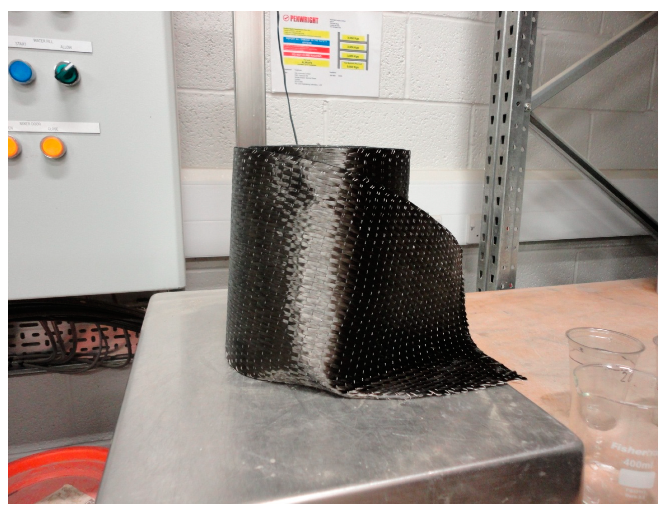
In this study, the carbon fibre-reinforced polymer composites (CFRP) with a resin epoxy matrix were attached to the masonry triplets (Figure 1 and Figure 2). In the current research, the use of these composites was based on the manufacturer’s technical report. The thickness of CFRP was 0.3 mm. The characteristics of CFRP and resin are presented in Table 1 and Table 2.
2.2. Mechanical Properties of Brick, Mortar, and Triplets
The controlling factor of brick is its compressive strength. Bricks with various strengths are available, depending on architectural necessities. For low-rise buildings, bricks of 5.2 N/mm2 should be sufficient. For damp-proof courses, low-absorption engineering bricks are usually required. For reinforced and pre-stressed brickwork, it is highly unlikely that brick with a strength lower than 20 N/mm2 will be used in the United Kingdom. The sand for mortar must be clean, sharp, and free from salt and organic contamination. Most natural sand contains a small quantity of silt or clay. A small quantity of silt improves workability. Loam or clay is moisture-sensitive and, in large quantities, causes the shrinkage of mortar. Marine and estuarine sand should not be used unless washed completely to remove magnesium and sodium chloride salts, which are deliquescent and attract moisture. Masonry cement is a mixture of approximately 75% ordinary Portland cement, an inert mineral filler, and an air-entraining agent. The mineral filler is used to reduce the cement content, and the air-entraining agent is added to improve the workability. Mortar made from masonry cement will have lower strength compared to a normal cement mortar of a similar mix. The main elements influencing the performance of masonry buildings are their mechanical characteristics, such as the triplets, mortar, and bricks’ elastic moduli (also known as Young’s modulus). Experimental tests were created for this study in order to determine the masonry and mortar samples’ elastic moduli. Furthermore, the samples’ compressive strength was determined due to the strong association between them and the elastic modulus. Cylinder specimens were built in order to assess the compressive strength and elastic modulus of mortar. The masonry specimens were built using solid London bricks and mortar M4 with a thickness of 10 mm between each brick layer. The horizontal surfaces of all samples were checked for bubble levels. After the construction of each sample, it was cured, and its design capacity developed for more than 28 days. The axial compression test was conducted with an average load application rate of 0.6 kN/s, according to the compressing test machine manual, and each test lasted 15 to 20 min.
2.3. Measurement of the Elastic Modulus of Triplet Masonry Samples
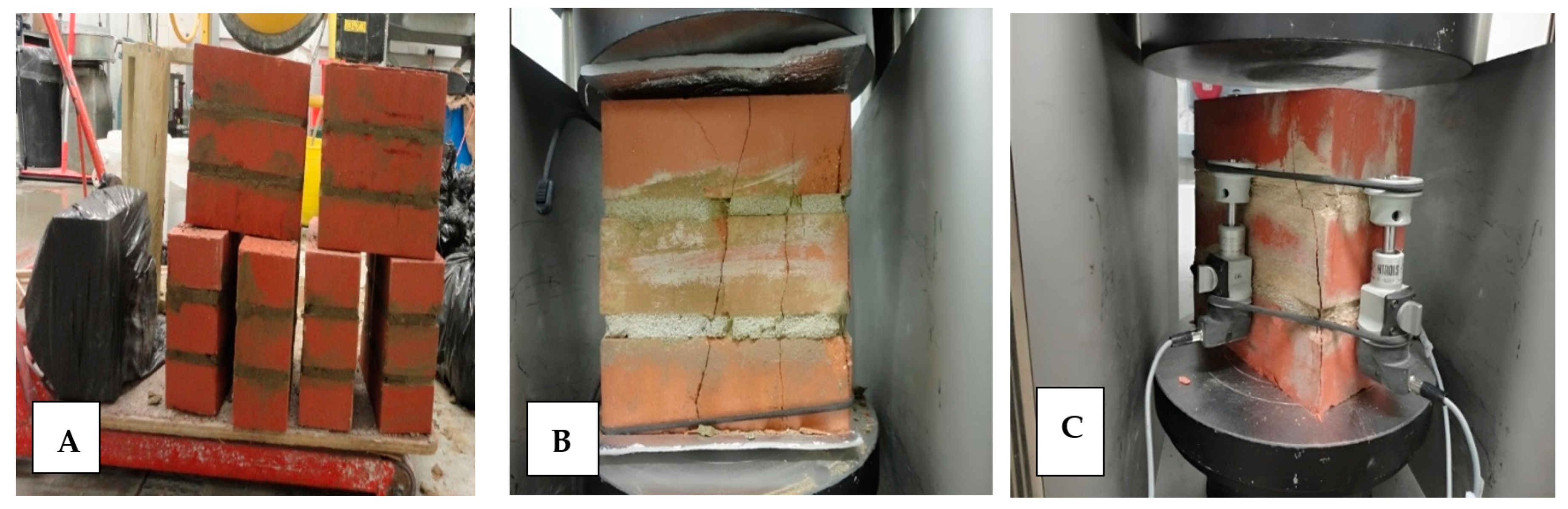
Overall, three full-scale specimens were constructed with a nominal dimension of 215 mm × 104 mm × 65 mm (height, length, and thickness). The masonry triplets were built with solid clay bricks, and the thickness of mortar for each layer of the triplets was approximately 10 mm (Figure 3A). Due to the high water absorption capacity of bricks, the bricks were soaked before building the specimens so that the rapid absorption of mortar water, which leads to degradation of mortar and thus degradation in the joint (bonding) between bricks and mortars, could be prevented. When the brick wall construction was finished, for curing, the walls were wetted twice a day for three days. The horizontal surface of all specimens was checked for bubble level. The axial compressive load at a rate of 0.6 kN/s was applied to each sample, and after loading, the deformation was measured using the universal testing machine called Advantest 9, MCC 8—Multifunctional Control Console, and three mechanical strain gauges attached to the sample. This test was repeated six times (Figure 3B,C).
2.4. Measurement of the Elastic Modulus of London Solid Brick Samples
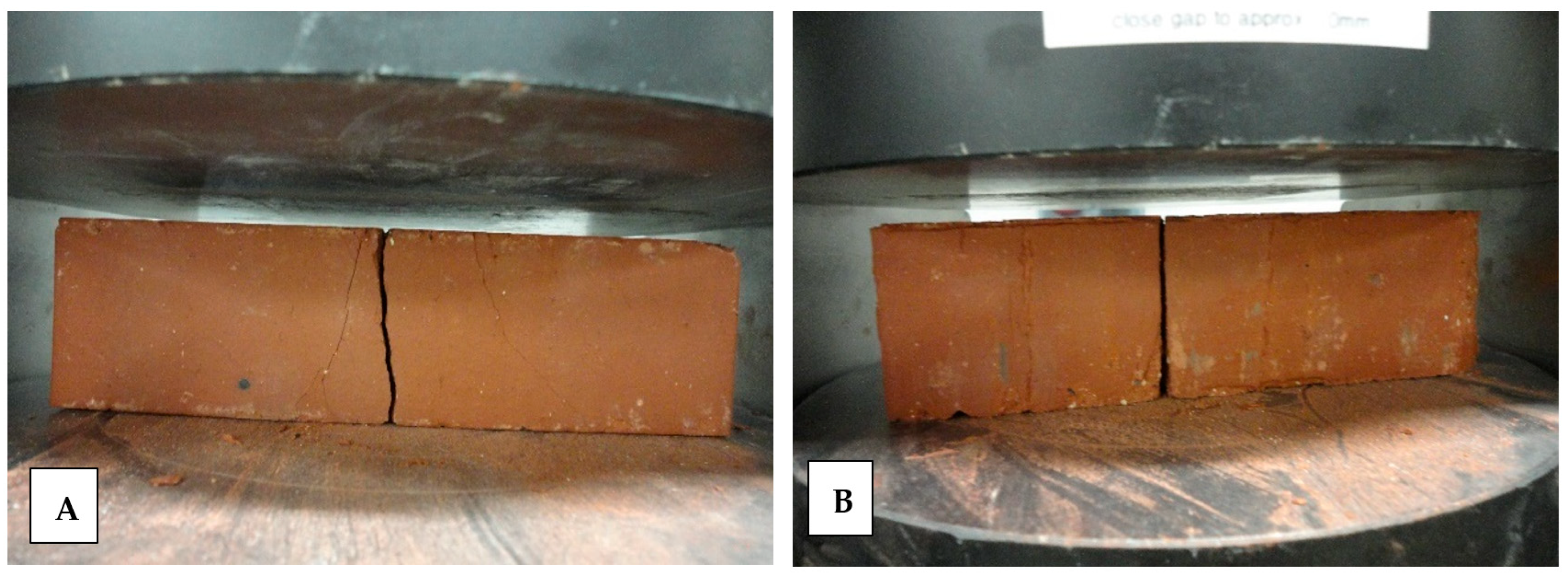
In this study, the bricks were tested under compression to find the modulus of elasticity and compressive strength. Six bricks were tested with an average size of 220 mm × 104 mm × 65 mm. The specimens were tested under load control in the universal testing machine. Based on compressive strength, stress, and strain, the average modulus of elasticity of the bricks was calculated. To measure the elastic modulus of brick samples according to the testing machine manual, a compressive load with a rate of 0.6 kN/s was applied to the sample (Figure 4A,B). The distributed load was applied to the surface of the sample, and after loading, the deformation was measured by a mechanical strain gauge in the machine.
2.5. Measurement of the Elastic Modulus of Mortar M4 Samples
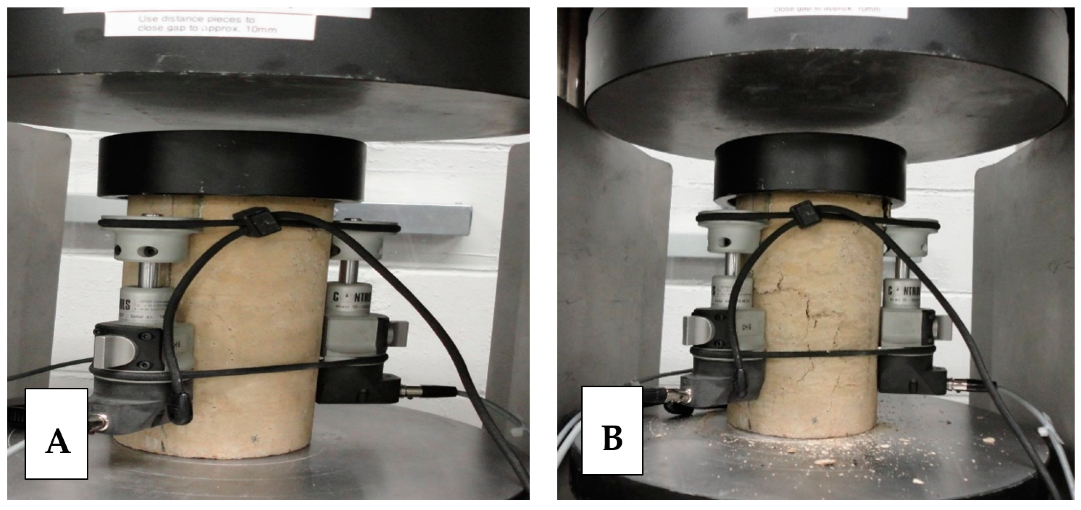
Twelve mortar cylinders were constructed with mortar M4 (1: ordinary Portland cement and 4: natural river sand, and the water–cement ratio was determined to be 1:3). To mix and prepare all the mortar specimens, regular tap water was used and mixed with an electric mixer. Mortar specimens were first cleaned of any loose material leftover from the previous test. To measure the elastic modulus of mortar samples, three strain gauges were attached to each sample, and an axial compressive load with a rate of 0.6 kN/s was applied to each sample, according to the testing machine manual (Figure 5A). All mortar specimens failed immediately after reaching the ultimate failure load. The failure mode of mortar specimens is presented in Figure 5B. All mortar specimens showed similar failure modes, expressed by crushing the specimen over the whole height at the end of loading. The deformation was measured using a mechanical strain gauge attached to the sample.
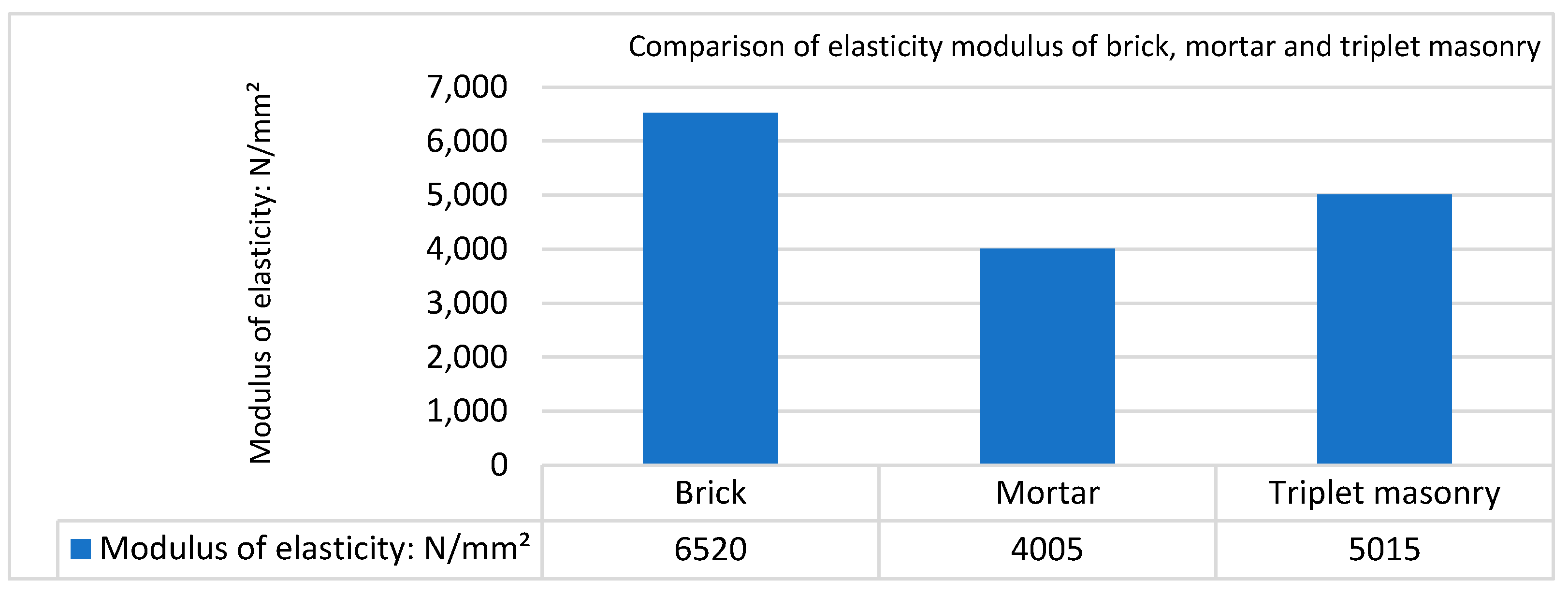
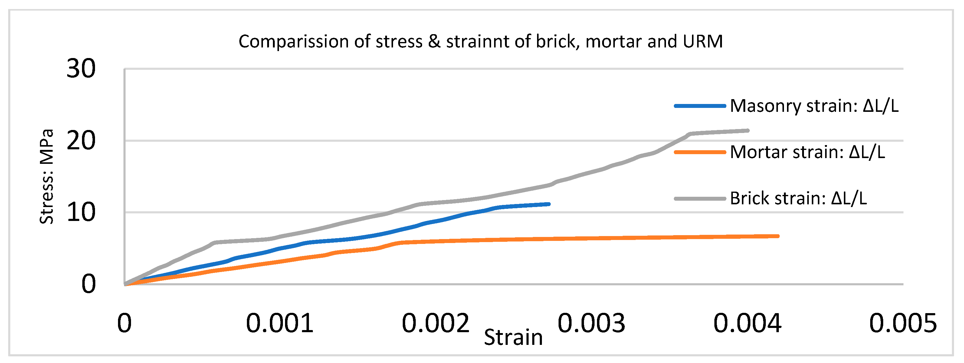
Figure 6 illustrates the comparative elastic modulus of brick, mortar M4, and triplet masonry, emphasizing variations in their resistance to deformation under stress. As expected, bricks exhibited a higher elastic modulus compared to mortar. Furthermore, Figure 7 displays the test outcomes of the stress-strain curves for triplet masonry, mortar, and bricks, including comparative curves. The stress-strain curve data indicates that the solid London brick exhibited a higher maximum compressive strength compared to mortar M4. This difference in strength between the brick and the weaker mortar joint contributed to a reduction in the overall compressive strength of the masonry.
3. Experimental Study on the Bond Behaviour of Strengthened Triplets under Shear Loading with Different CFRP and CFRP Net Configurations
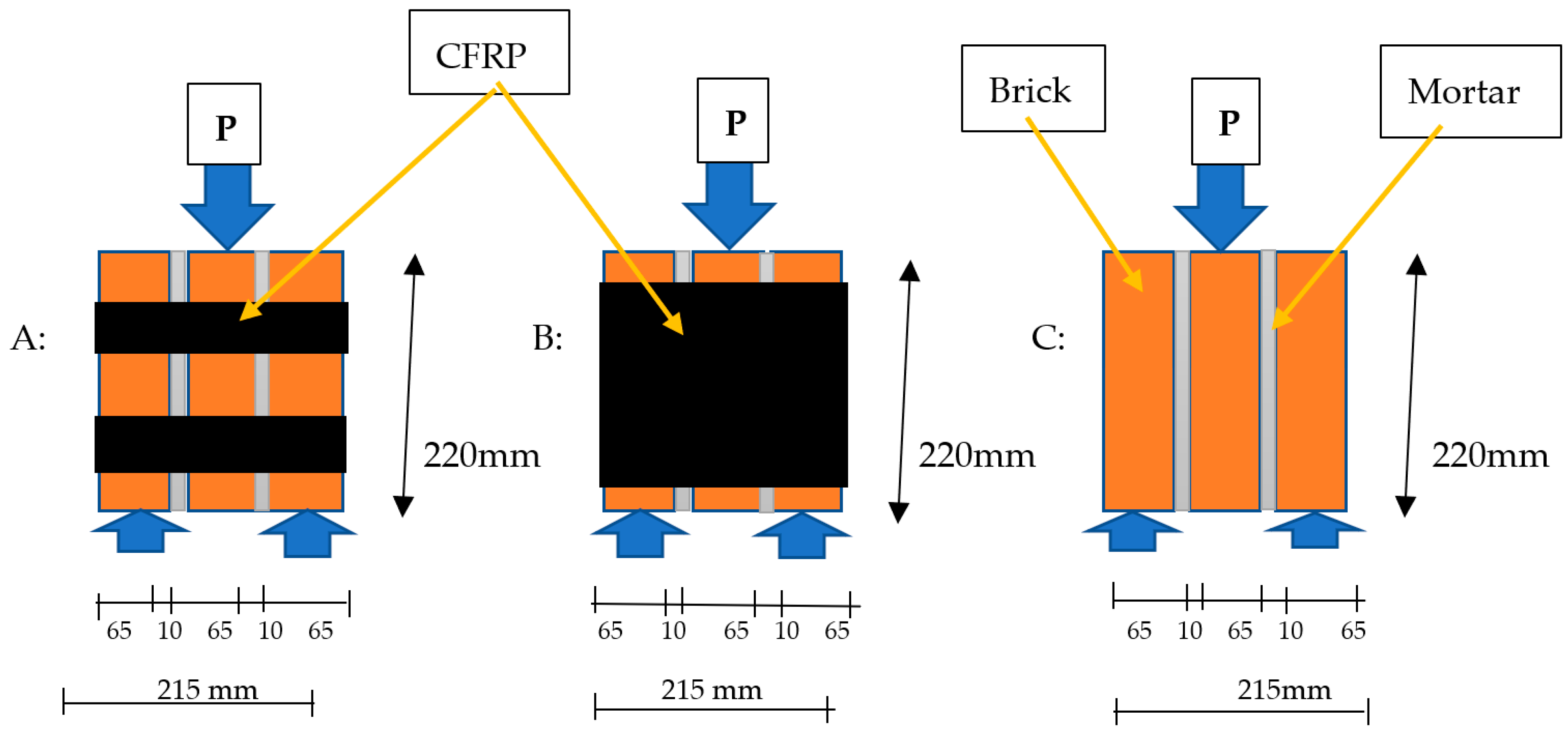
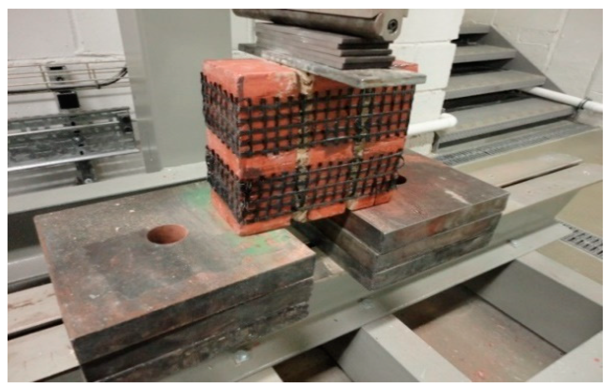
Masonry can present different failure modes depending on the geometry, material, and load factors. According to Zimmermann et al. [29] and EN 1052-3 [30], the initial shear strength of masonry must be derived from the strength of small masonry specimens tested to destruction. The tests were conducted on specimens with dimensions of 220 × 103 × 215 mm prepared from solid clay bricks and mortar. All specimens had three brick units and a 10 mm joint thickness in between. The specimens were cured in the laboratory under controlled environmental conditions. Each specimen was tested at the age of 40 days. Bond stresses in the unit–mortar interface were introduced by gradually increasing the applied forces until failure. The experimental tests of masonry triplets were carried out with one-layer CFRP to evaluate the brick–mortar bed joints and bond stress-slip relationships of CFRP-strengthened triplet masonry. Additionally, the main goal of the present study was to evaluate how externally bonded CFRP composites improved the bond strength and deformation capacity of brick–mortar joints. For this reason, loads were applied to the triplet masonry assemblage in the current investigation, parallel to the bed joint. The loading has to be applied to the mortar joint interfaces between the centre brick and the side bricks in order to achieve the aforementioned goal. In order to do this, the side bricks were supported at the bottom, and the central brick was loaded at the top (Figure 8). Moreover, each experimental test was repeated on four specimens.
3.1. Triplet Masonry Test without CFRP
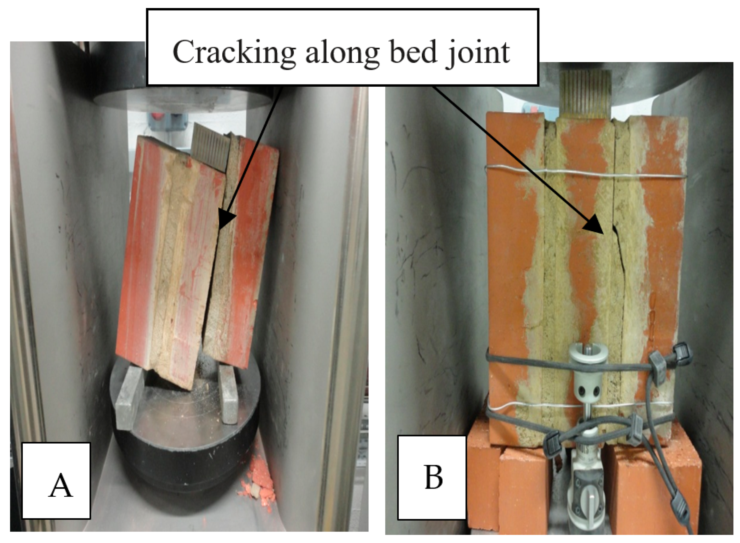
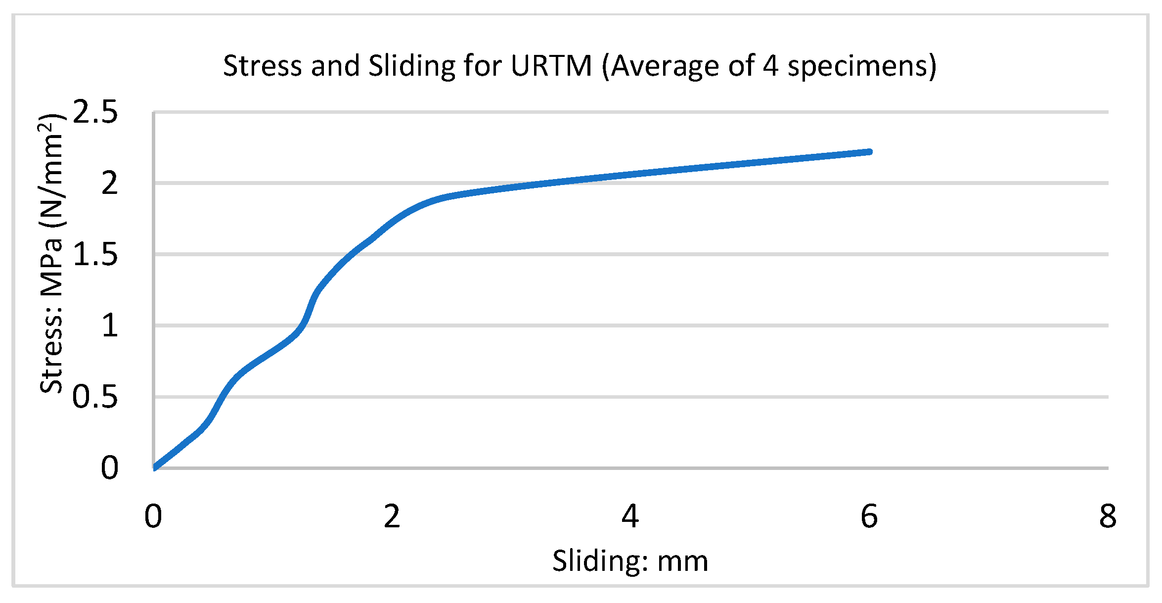
A pre-compression test was carried out on unreinforced masonry triplets constructed with mortar M4 to evaluate the main brick–mortar interface characteristics. These specimen prisms are placed longitudinally under the load that applies to the head of the middle brick masonry unit. This experiment can be done with or without a lateral pre-compression load. Four URTM specimens were constructed without FRP as control samples. The samples suddenly failed at 10 kN, 10 kN, 12 kN, and 13 kN. The mode of failure under in-plane loading was sudden and brittle in all specimens. The specimens failed due to the development of cracks along the interface between brick and mortar, followed by complete collapse, as shown in Figure 9A,B. The failure (cracking) in the mortar joints was either confined to one of the interfaces (Figure 9A) or to the inner-to-outer interface (as viewed in the direction of loading), as shown in Figure 9B (the upper interface of the specimen on the right side cracked horizontally). As expected, low bond strength of masonry specimens was obtained, and all triplets failed in the brick–mortar interface by shear sliding. This failure is one of the valid failures established by EN 1052-3 [30]. The stiffness of the stress-slip behaviour increases in the early portion of the curve, as seen in Figure 10. This phenomenon can be attributed to the effect of dilatation; the control triplet specimens’ average ultimate displacement was 2.0 mm. The maximum load and final displacement of the control triplets in this study and the ones tested by Mojsilovic [31] are comparable. Failures in the mortar layer were the primary source of the failure modes. As the load increased, a diagonal crack appeared in the mortar layer and spread throughout the mortar. As a result, the specimen split into two separate parts that came from either the outer or inner brick, or from both. No considerable damage was seen on the brick sides. A similar failure mode was similar to that reported by Prakash [32] and Bompa et al. [33]. All triplet specimens failed similarly, and failure occurred mainly in the mortar joints. The specimens demonstrated failure in the joint with the relative movement of the middle brick.
3.2. Reinforcement with One Layer of CFRP on Two Sides
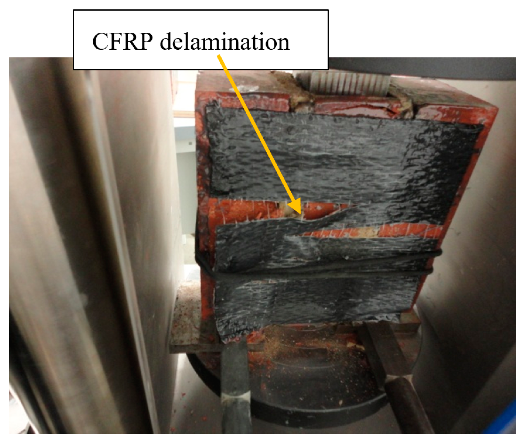
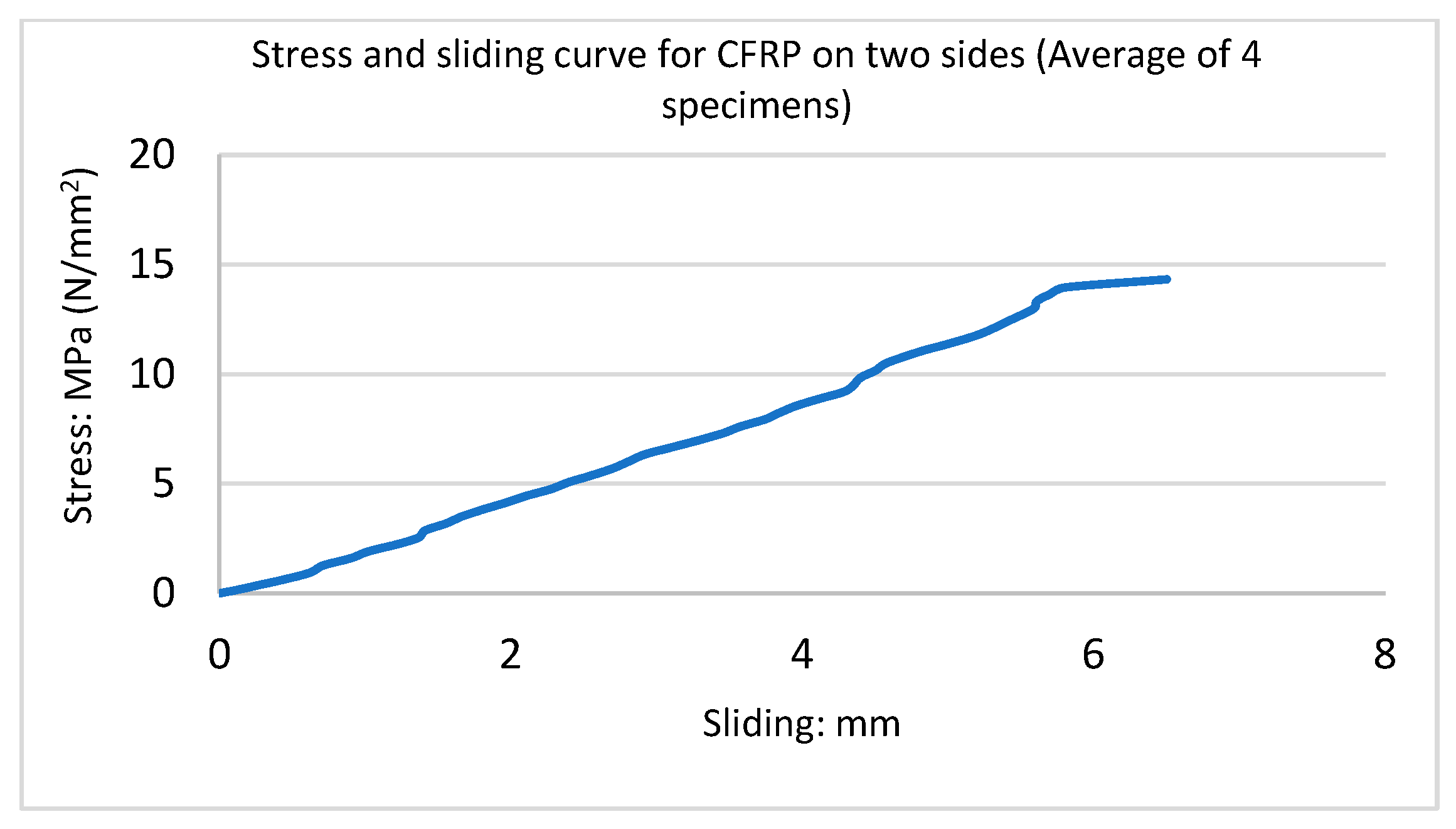
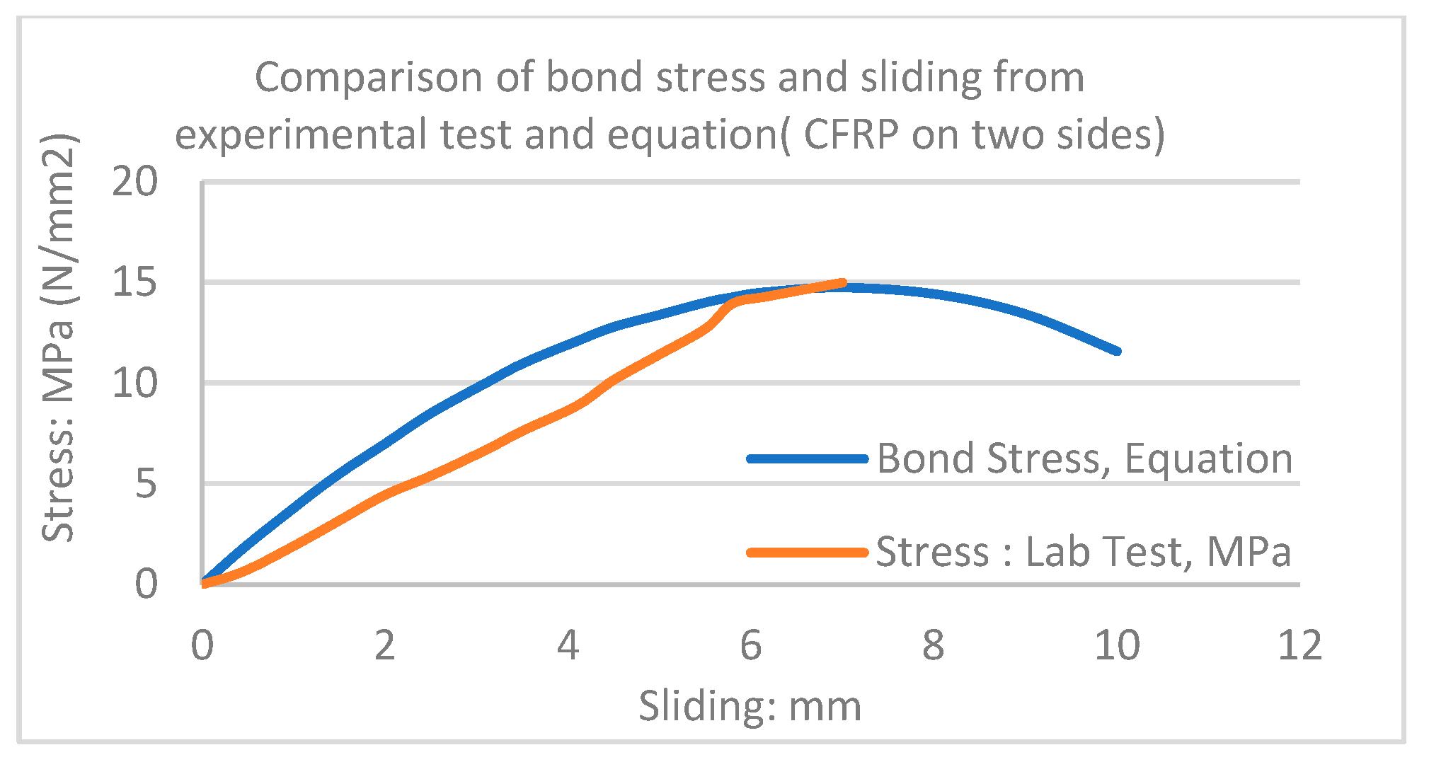
Four samples were constructed and strengthened with one layer of CFRP sheet on two sides of triplet masonry. CFRP composites were attached to masonry triplets. Before applying CFRP, minor imperfections, such as small pieces of mortar, were removed to gain a flat surface by scrubbing the specimens with sandpaper. Epoxy resin was mixed with a hardener, according to the manufacturer’s manual. The resin was applied to the prism’s surface, followed by the application of FRP to the masonry triplets. The sliding was measured by a mechanical gauge in the testing machine. The ultimate load was approximately 84 kN, and the mode of failure was ductile. Debonding also occurred just before failure; the FRP ruptured at mid-span, followed by shearing of the sheets at the bottom. Debonding occurs when stresses transferred by the CFRP composite exceed the tensile strength of the substrate material. This causes the CFRP to peel off from the brick. The failure in the unit–mortar interface is shown in Figure 11. Figure 12 illustrates the stress-sliding curve. In this test, the triplet masonry with one layer of CFRP sheets on two sides was seven times stronger than the URM samples.
The CFRP reinforcement stopped the micro-cracks from expanding through the mortar layer and prevented the early shear failure of the triplet. This demonstrated how the CFRP reinforcement supported the bed joints’ tensile load. The primary cause of the failure of CFRP-strengthened triplet masonry was the debonding of CFRP from triplet; this failure generally happens when the bonding between the reinforcement composite and masonry interface is lost. Reinforced triplets, as compared with URM walls, remained stable after failure. Before the masonry cracked and the stress dropped, it was found that the triplet had a nearly linear stress-slip relationship.
3.3. Strengthening with One Layer of CFRP Net on Two Sides of Triplet
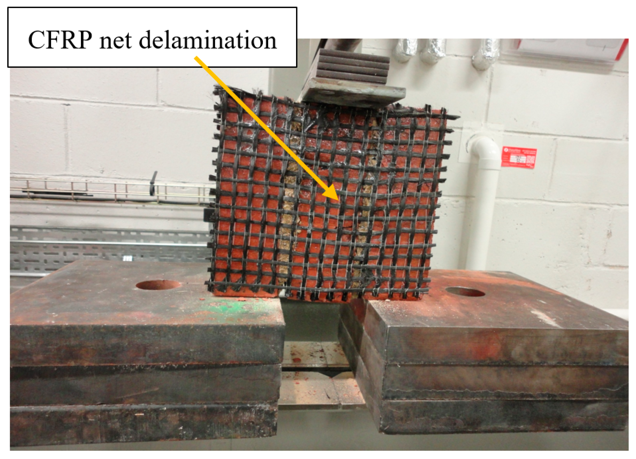
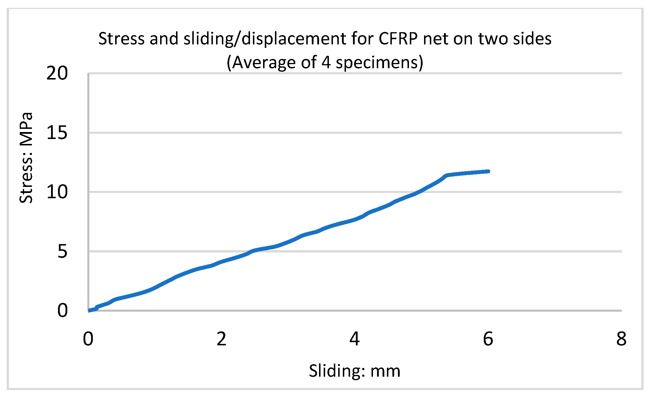
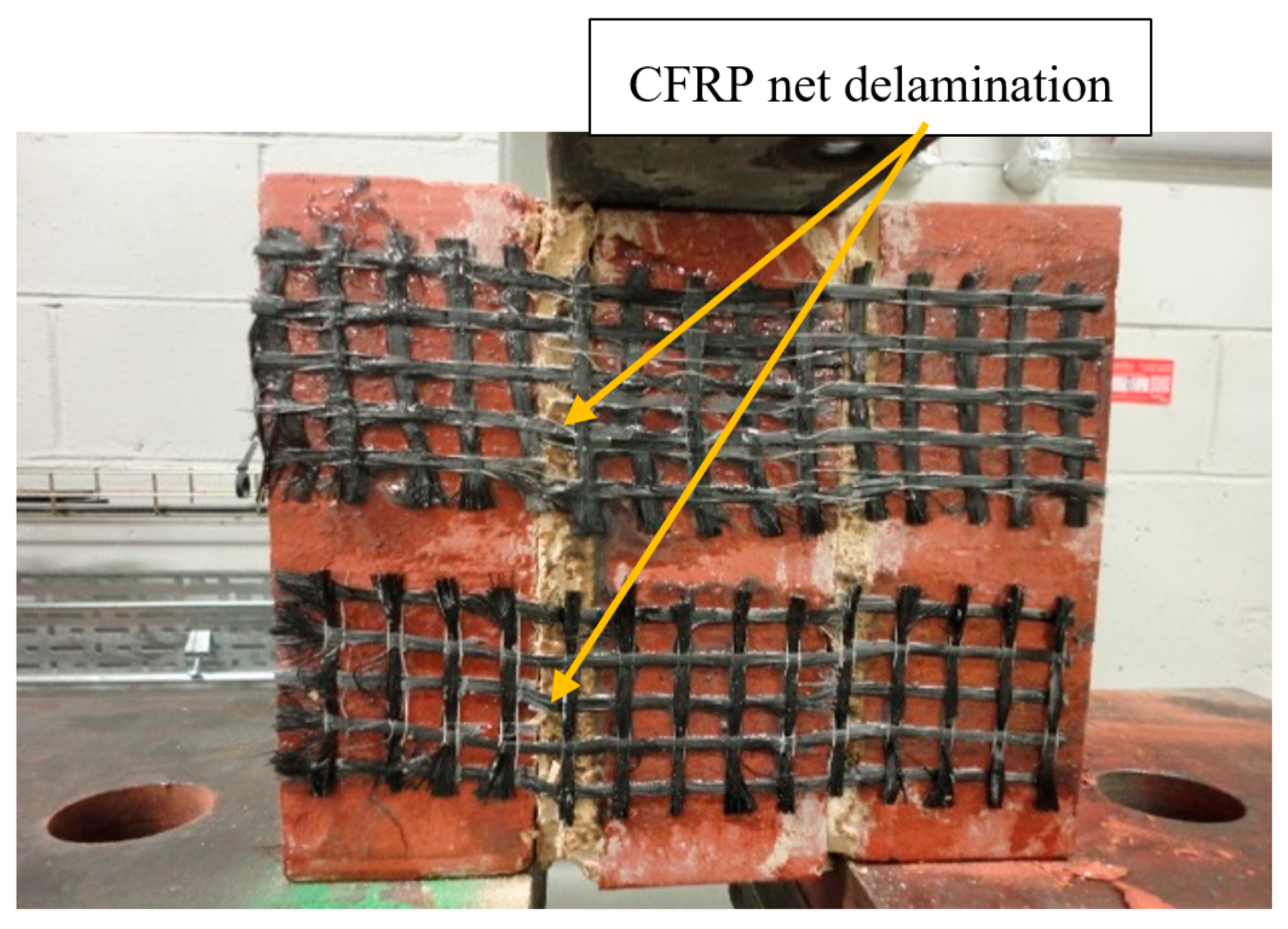
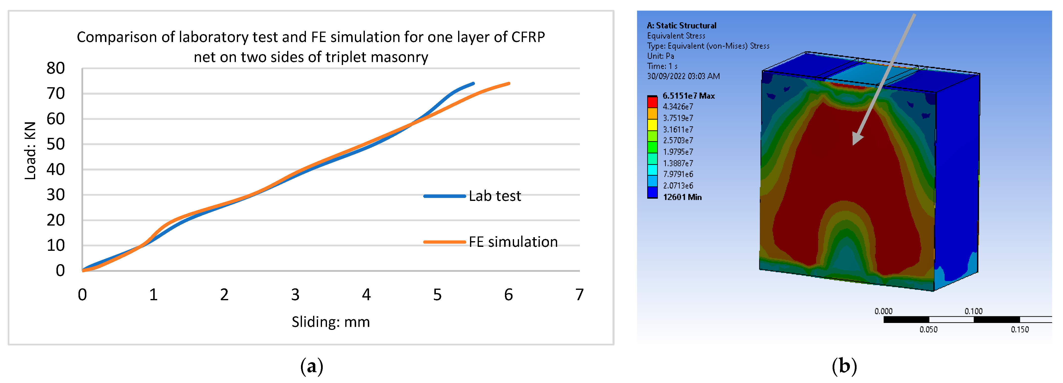
These samples were strengthened with one layer of CFRP net on two sides of the triplets. The mode of failure was observed to be ductile, and the ultimate load was approximately 71 kN. These triplets also displayed the propagation of cracks, as did the previous test. Delamination before failure and failure in the unit–mortar interface also occurred, as shown in Figure 13. Figure 14 illustrates the stress-slip curve; the initial slope of the load-displacement curves for a CFRP net on four sides and CFRP on two sides of triplet specimens were almost equal. In this test, the triplet masonry with one layer of CFRP net on two sides was six times stronger than the URM samples, and the ultimate load capacity of CFRP net glued on four sides and two sides was almost equal. Shear cracks in the mortar layer began to appear at the brick–mortar interface, which is where the cracking in the specimen reinforced with CFRP net on two sides occurred. Before the mortar cracked and the stress dropped, it was found that the triplet had an almost linear stress-sliding behaviour.
3.4. Strengthening with One Layer of CFRP Strip on Two Sides of a Triplet
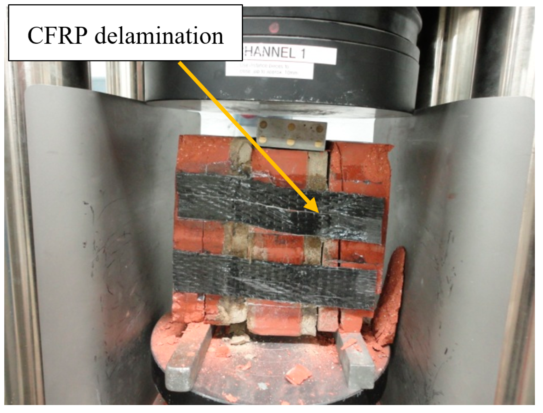
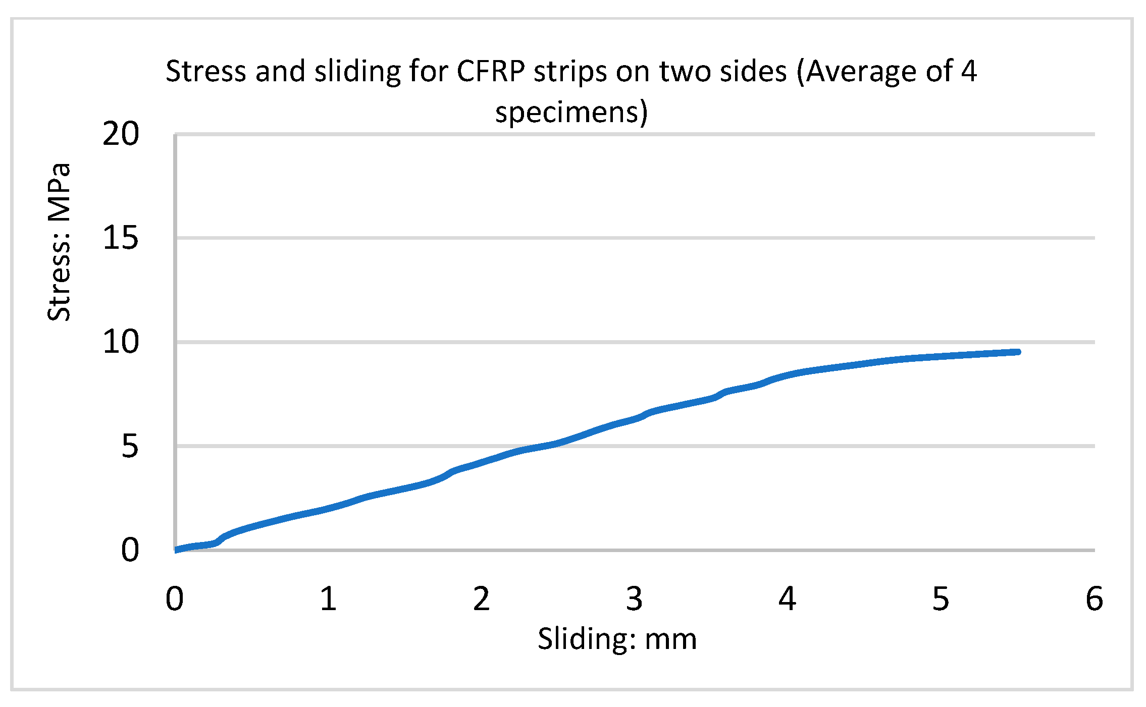
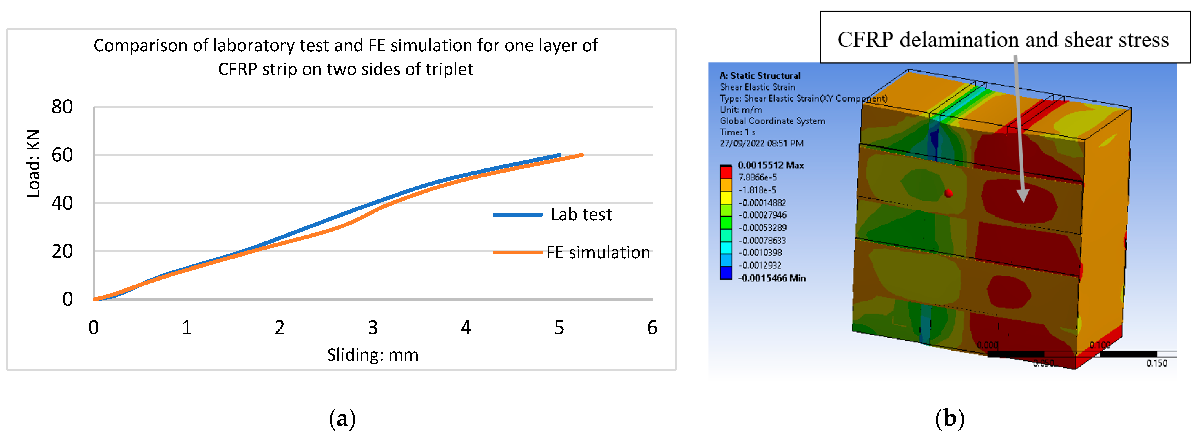
The samples were reinforced with one layer of CFRP, a 50 mm wide strip on two sides of triplets. The mode of failure was ductile, and the ultimate load was approximately 57 kN. These triplets also displayed the propagation of cracks, as did the previous test. Delamination also occurred before failure. The failure in the unit–mortar interface is shown in Figure 15. Figure 16 shows the stress-sliding curve; the triplet masonry with one layer of CFRP strip on two sides was four times stronger than the URM samples. The presence of the CFRP improved the performance by changing the brittle failure to a ductile failure. In the strengthened triplets, the failure occurred due to the loss of bonding between the CFRP and the masonry units. The crack was formed by the debonding of the brick from the mortar until the debonding of the epoxy from the masonry units. At this point, the triplet failed because the tensile stresses were no longer transferred to the CFRP.
3.5. Strengthening with One Layer of CFRP Net Strip on Two Sides
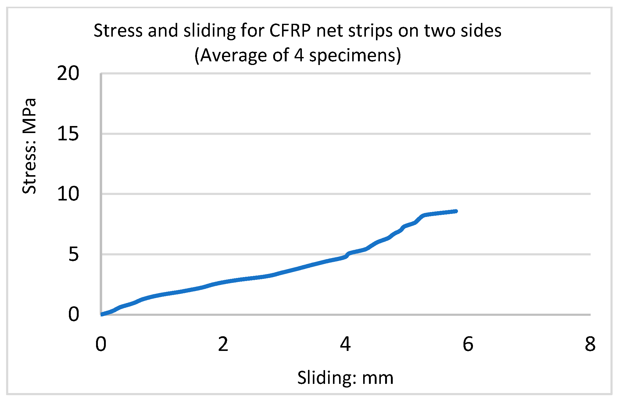
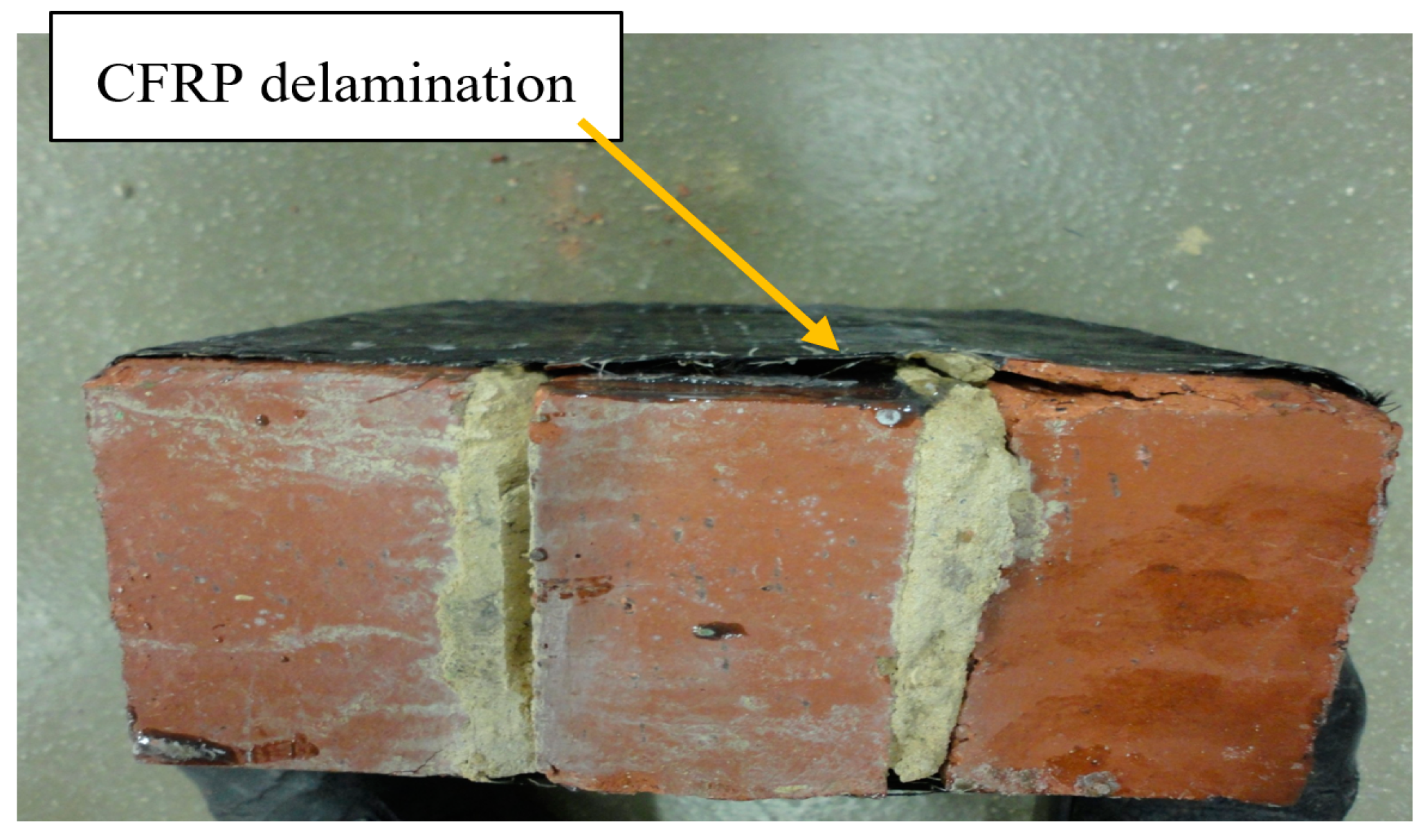
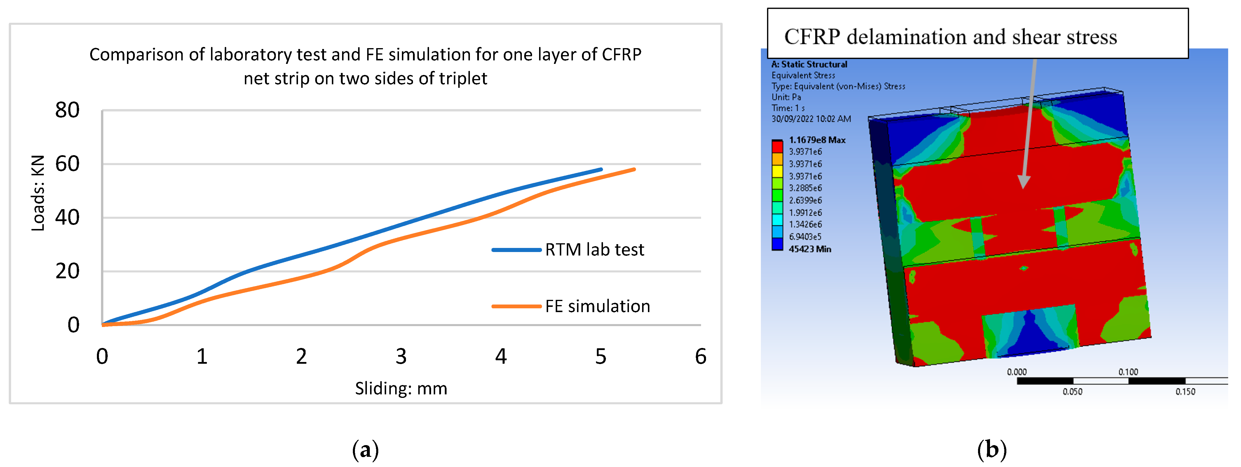
These samples were strengthened with one layer of two CFRP net strips, 50 mm wide, on two sides of the triplet. The mode of failure was observed to be ductile, and the ultimate load was approximately 52 kN. The triplets also displayed the propagation of cracks as per the previous test, and delamination occurred before failure. Figure 17 illustrates failure in the unit–mortar interface, and Figure 18 shows the stress-sliding curve. In this test, the triplet masonry with one layer of CFRP net strip on two sides was four times stronger than the URM samples. The debonding of CFRP from triplet was the main reason for the failure of the CFRP-strengthened triplet masonry.
3.6. Strengthening with One Layer of CFRP Wrapping on Four Sides
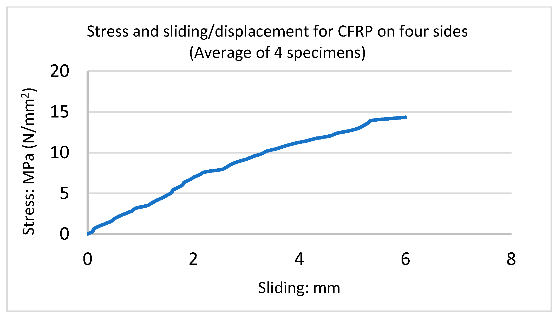
Samples were strengthened with one layer of CFRP on four sides of the triplet. The mode of failure was observed to be ductile, and the ultimate load was about 88 kN. These samples also displayed the propagation of cracks as did the previous test, and delamination also occurred before failure. The shear failure in the unit–mortar interface is shown in Figure 19. Figure 20 shows the stress-sliding curve. In this test, the triplet masonry with one layer of CFRP on four sides was six times stronger than the URM samples. The maximum load capacity of CFRP sheets on four sides and two sides is nearly the same, but reinforced triplets on four sides showed less displacement.
3.7. Strengthening with One Layer of CFRP Net on Four Sides of Triplet
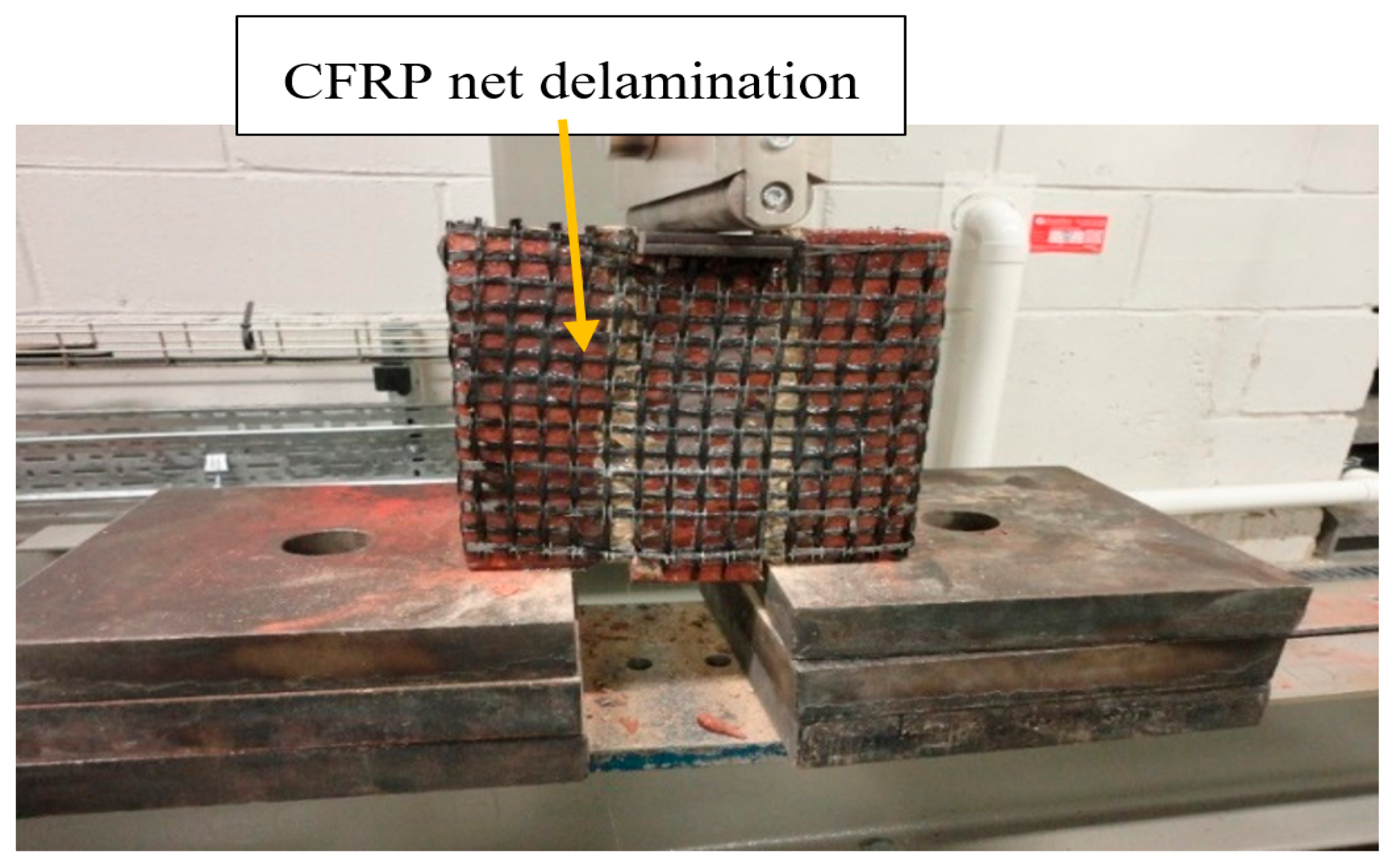
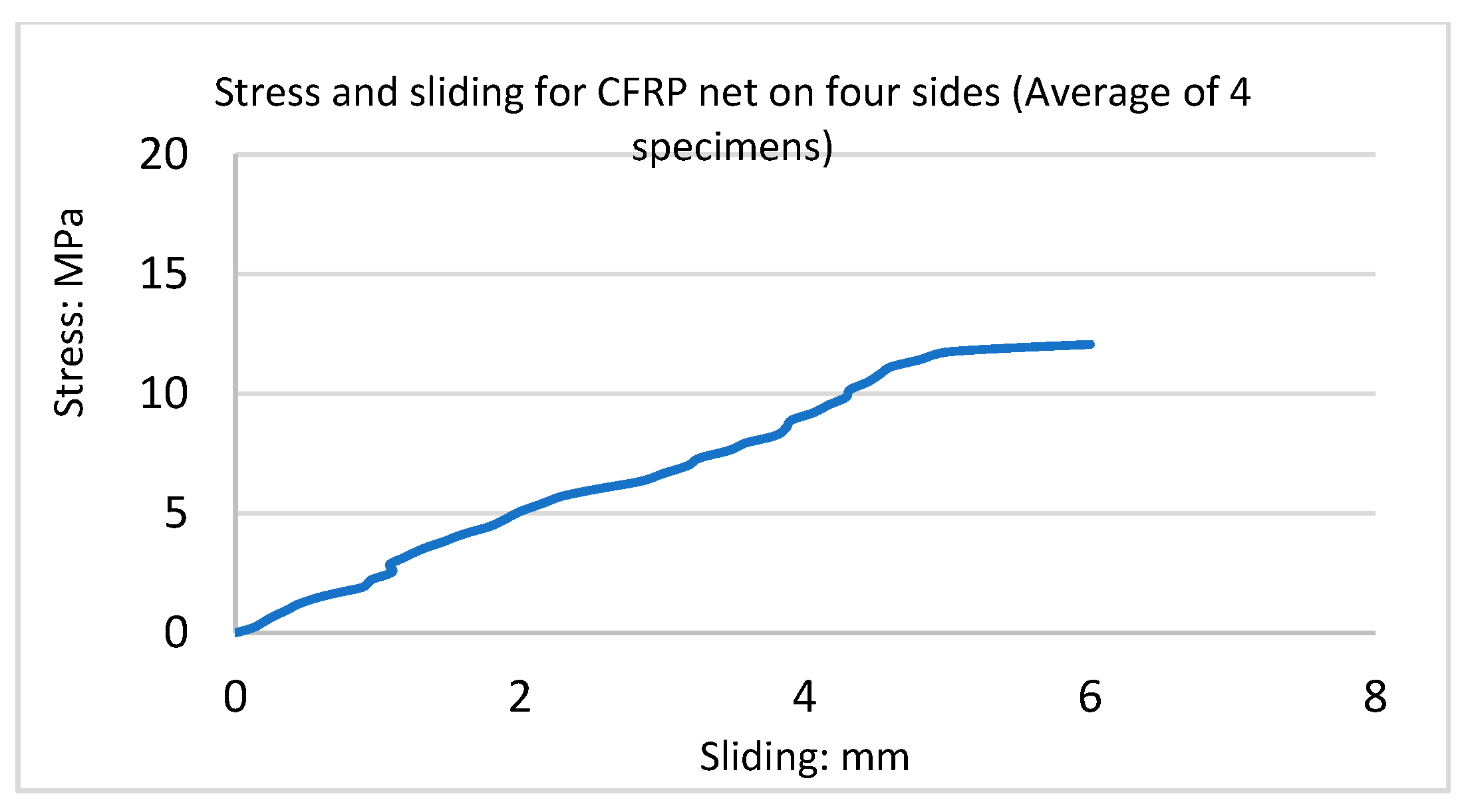
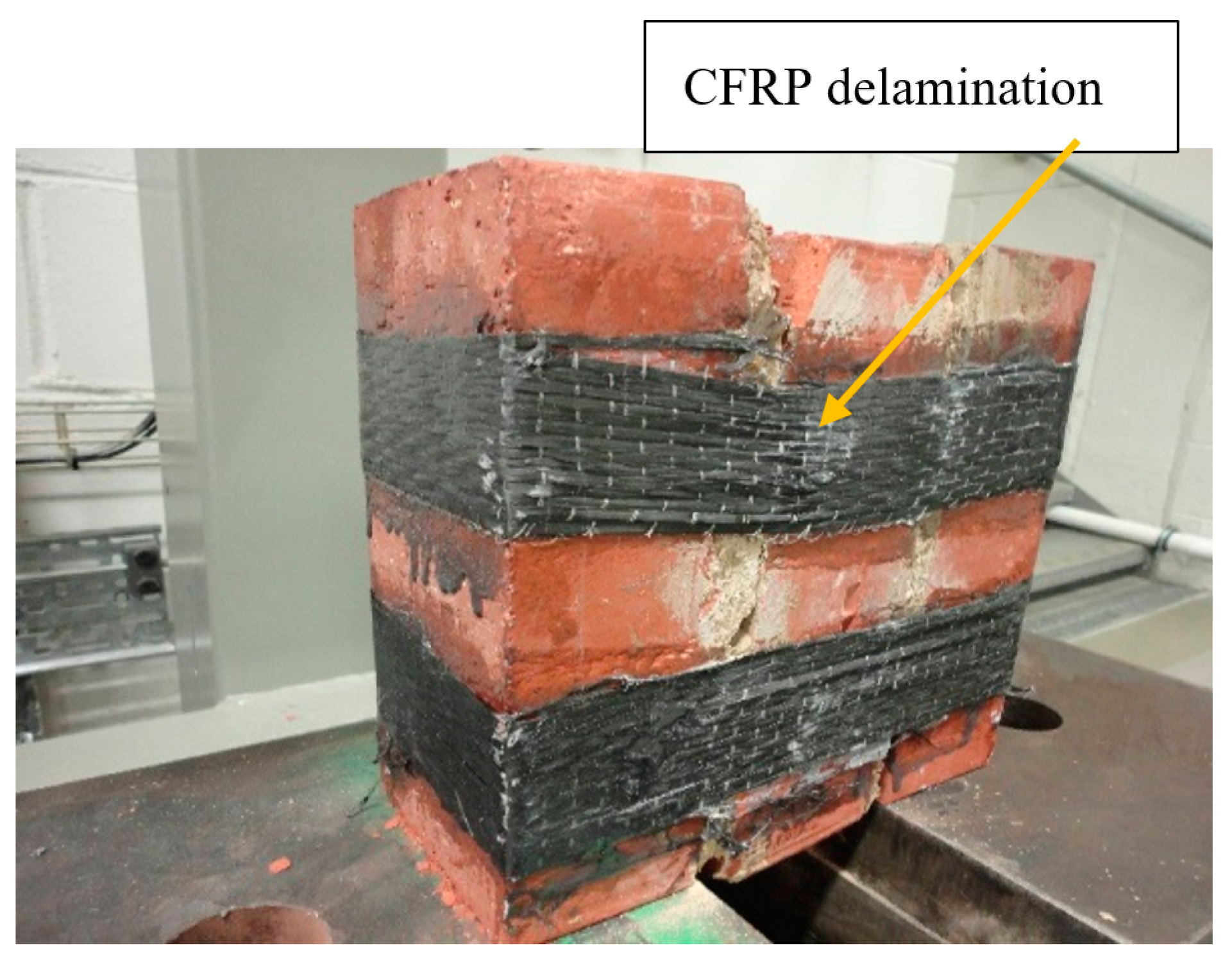
These samples were strengthened with one layer of CFRP net on four sides of triplet masonry. The mode of failure was observed to be ductile, and the ultimate load was approximately 78 kN. Debonding occurs when stresses transferred by the CFRP composite exceed the tensile strength of the substrate material. This causes the CFRP net to peel off and cause damage to the triplet specimen. The shear failure in the unit–mortar interface is shown in Figure 21. Figure 22 displays the stress-sliding curve, and in this test, the triplet masonry was six times stronger than the URM samples. The failure in the specimens occurred through the development of sliding on the brick–mortar interface. The debonding of CFRP from triplet was the main reason for the failure of CFRP-strengthened triplet masonry, which mainly occurs when the bonding between the reinforcement composite and masonry interface is lost. In contrast to URM walls, reinforced triplets were stable after failure.
3.8. Strengthening with One Layer of CFRP Strip on the Four Sides of a Triplet
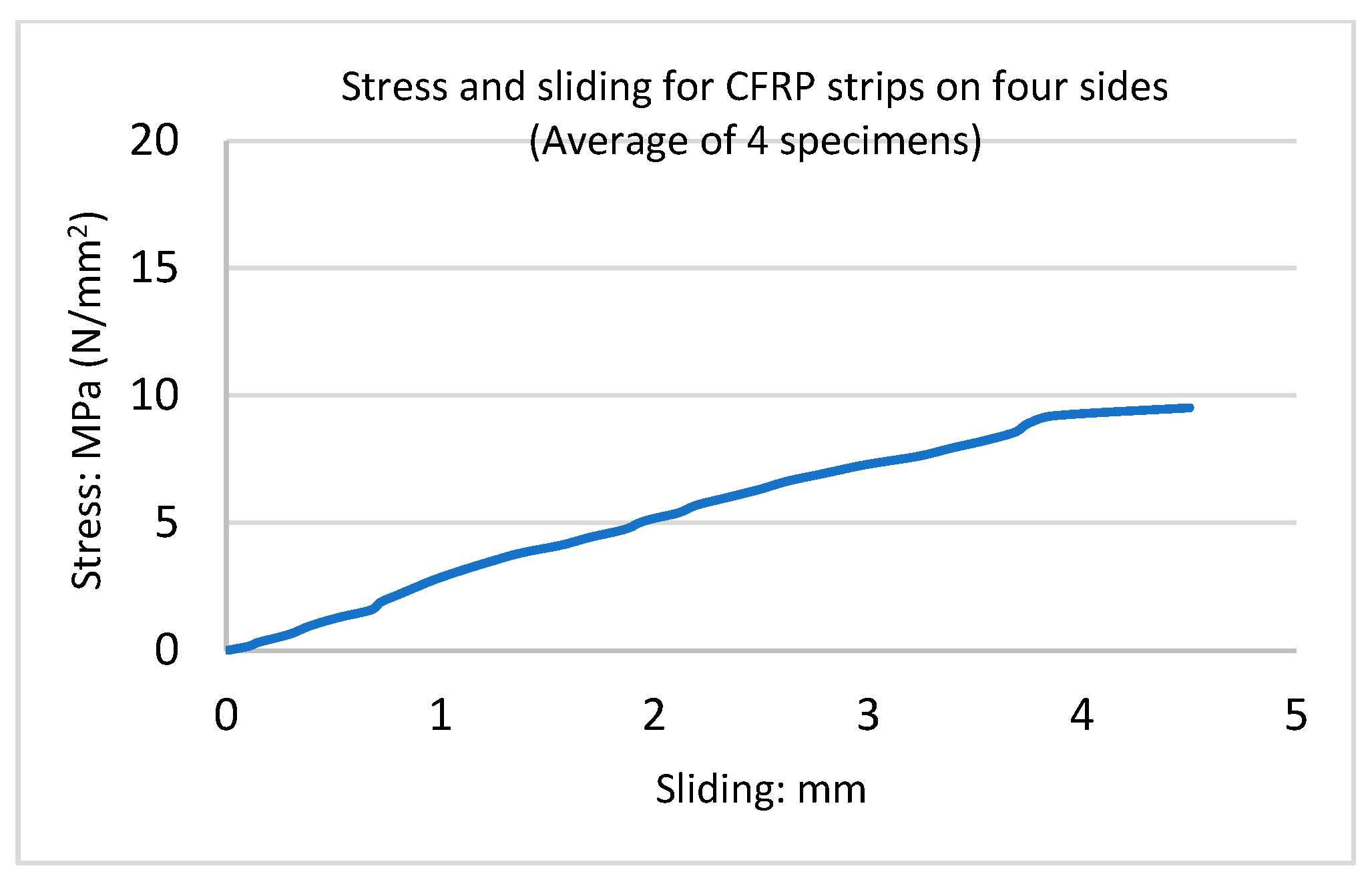
These samples were strengthened with one 50 mm wide layer of CFRP strip on four sides of triplet masonry. The mode of failure was ductile, and the ultimate load was approximately 57 kN, which was slightly stronger than CFRP strips on two sides of the triplet. The propagation of cracks and delamination also occurred before failure. Figure 23 presents the shear failure in the unit–mortar interface. Figure 24 displays the stress-sliding curve; triplet masonry with one layer of CFRP strip on four sides was five times stronger than the URM samples. The failure in the specimens occurred through the development of sliding on the brick–mortar interface; debonding of CFRP from the triplet was the reason for the failure of the CFRP-strengthened triplet.
3.9. Strengthening with One Layer of CFRP Net Strip on Four Sides
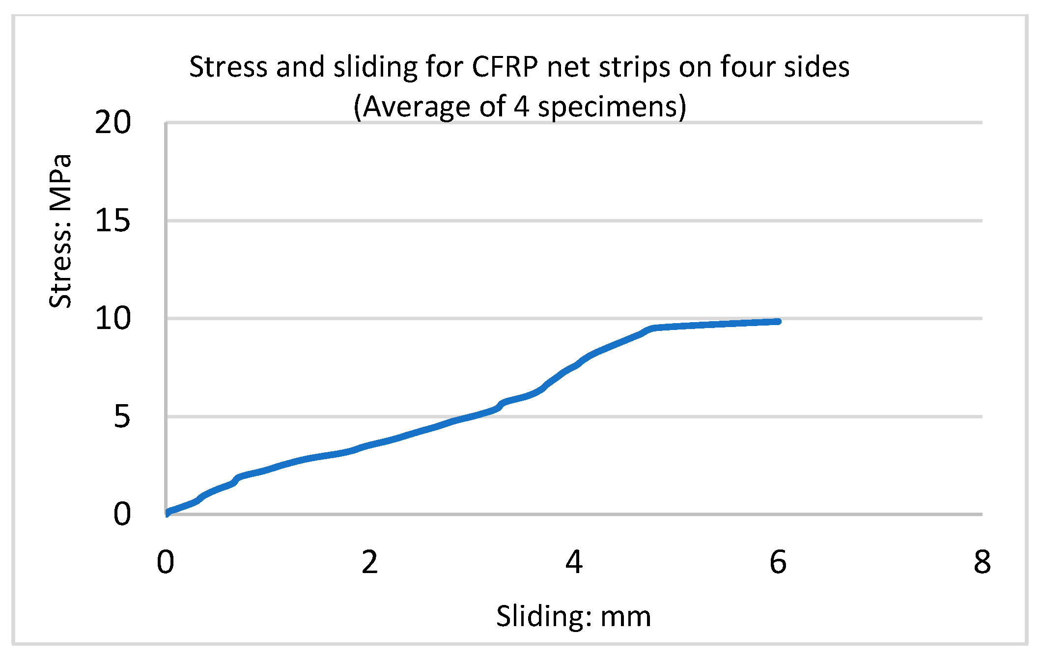
The samples were strengthened with one layer of two CFRP net strips, 50 mm wide, on four sides of the triplet. The mode of failure was ductile, and the ultimate load was approximately 60 kN. These triplets displayed the propagation of cracks and delamination that occurred prior to failure. The shear failure in the unit–mortar interface and brick is shown in Figure 25 and Figure 26, which illustrate the stress-sliding curves. Furthermore, it was observed that the shear triplet presented an almost linear shear stress–strain relationship before cracking of mortar, followed by a drop of shear strength. In this test, the triplet masonry with one layer of CFRP net strip on four sides was five times stronger than the URM samples.
Table 3 illustrates a comparison of bond stress and sliding from the experimental tests at failure points for the different CFRP configurations. The tests demonstrated that four sides covered with FRP and FRP strips resulted in stronger bonds and less displacement in triplet masonry. In addition, the FRP wrap performed better than the FRP strips.
4. Equation for Shear Behaviour of Triplet Masonry
4.1. Empirical Equations for the Shear Strength of URM
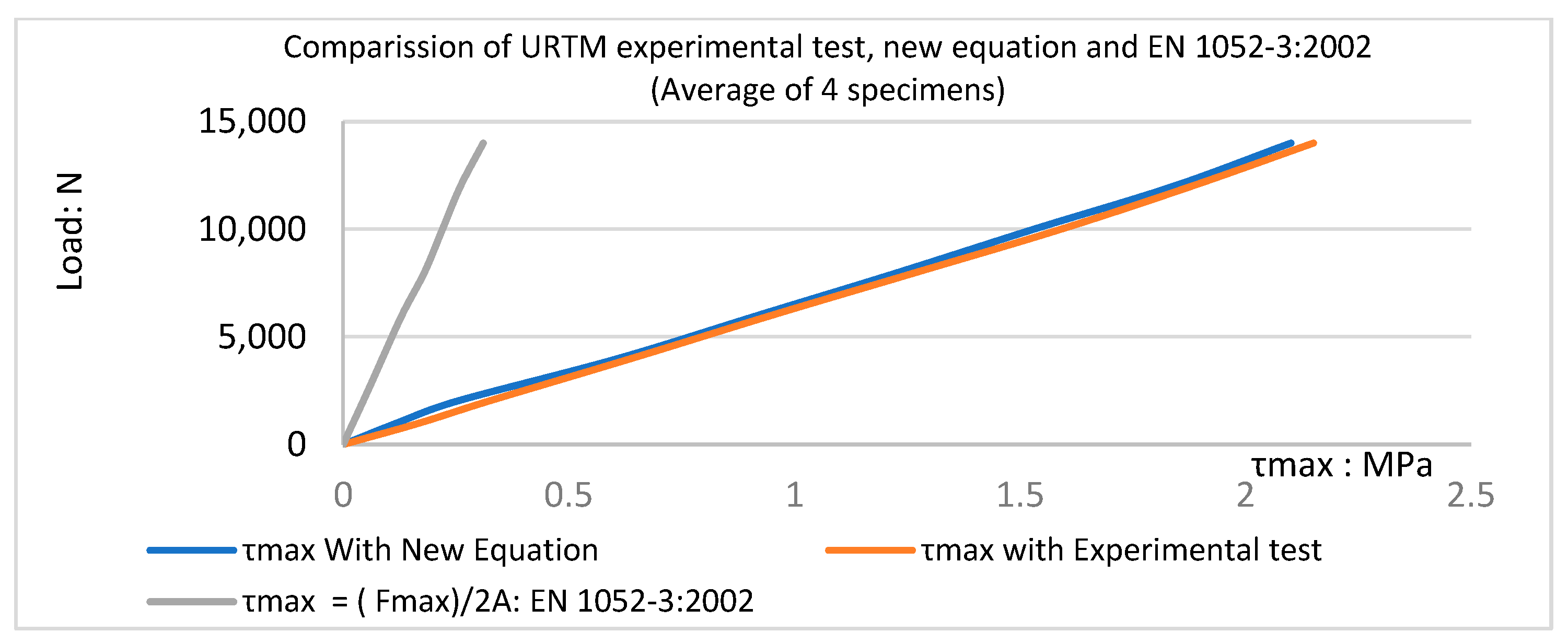
The results of the standard shear tests on triplets are presented in this section to derive empirical equations for the shear behaviour of unreinforced masonry elements. According to EN 1052-3 [30], the shear stresses can be assumed to be uniformly distributed over the two-bed joints during the triplet test. The following method can be used to evaluate the maximum value of the experimental shear stress τmax on the bed joints:
where τmax is the maximum value of the experimental shear stress, Fmax is the maximum shear force at failure, and A is the total area of the bed joint. Based on the experimental tests in the current study, the above equation demonstrated extremely low shear stress compared to experimental tests and was therefore unreliable. Thus, this equation was improved for maximum shear strength of triplet masonry with solid brick and mortar M4 as follows:
where ρ = 0.20 for mortar M4, A is the total area of the bed joint, and Fmax is the maximum shear force at failure. The coefficient of 0.70 was obtained based on experimental tests through trial and error. In this new equation, τ can be calculated at any shear load point. Table 4 and Figure 27 show the comparison of the experimental tests and the results from Equation (2).
4.2. New Equations for Strengthened Triplet Masonry with CFRP
As per codes of practice, information about shear tests on unreinforced and reinforced triplet masonry with CFRP is limited.
Therefore, the combined resistance offered by the FRP and the brick–mortar joint can be used to express the shear strength of masonry that has been strengthened with FRP.
where
Sm = Sm0 + Sfrp
Sm = reinforced masonry shear strength with FRP
Sm0 = shear resistance of the unreinforced masonry
Sfrp = additional resistance offered by FRP confinement
Sm0 can be calculated using formulas found in design guidelines such as IS: 1905 (BIS 2002a). In this research, Sm0 for solid London brick and mortar M4 was obtained from the shear tests performed on control triplet specimens (Equation (4)).
The expressions that quantify Sfrp needed to be developed. Below, the results of the experimental tests used to calibrate new expressions for Sfrp are presented.
Tensile stress in CFRP was caused by the centre brick slipping during the loading process. As the middle brick slipped further, the compressive stress on the bed joint grew until the specimen broke as a result of the FRP composite rupturing or debonding from the masonry. Consequently, a new equation (Equation (5)) could be used to express the maximum shear strength of CFRP:
where σfrp is the tensile strength of the CFRP, which is given by the factory. The average tensile strength of the CFRP and CFRP net was 3500 MPa.
Sfrp = σfrp × Af//At × K ×μf
Sfrp is the maximum shear strength of masonry with CFRP; At is the area of triplet masonry; Af is the area of triplet masonry covered by CFRP; k = 1, for one layer of CFRP on two sides; k = 0.7, for one layer of CFRP on four sides; μf is the coefficient for CFRP; and μf = 0.007 for CFRP.
Table 5 shows a comparison of the maximum shear strength of different configurations of the experimental triplet masonry strengthened with CFRP and the results from the new Equations (3) and (5).
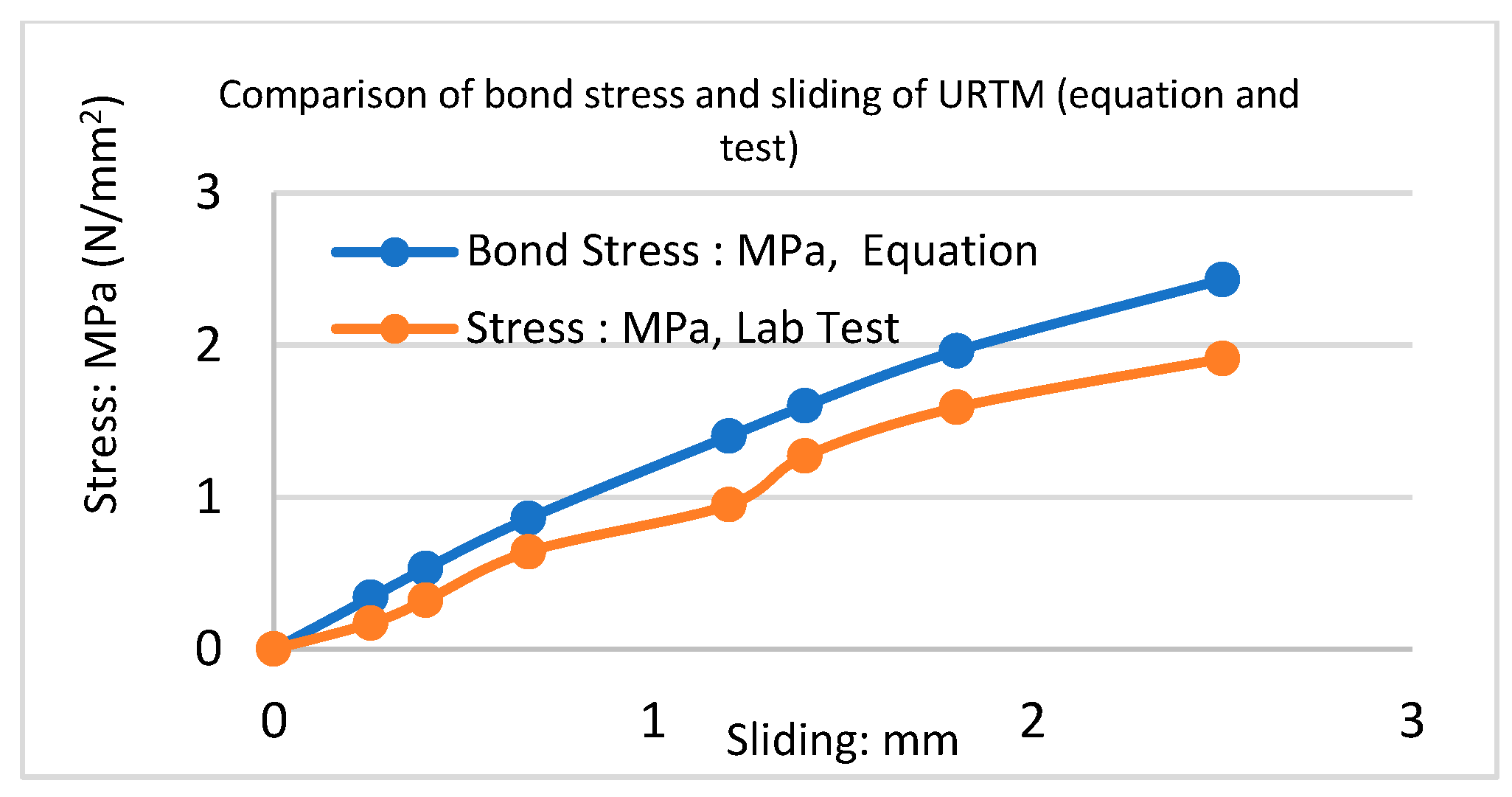
4.3. New Equations for Bond Stress-Slip of Strengthened Triplets with CFRP
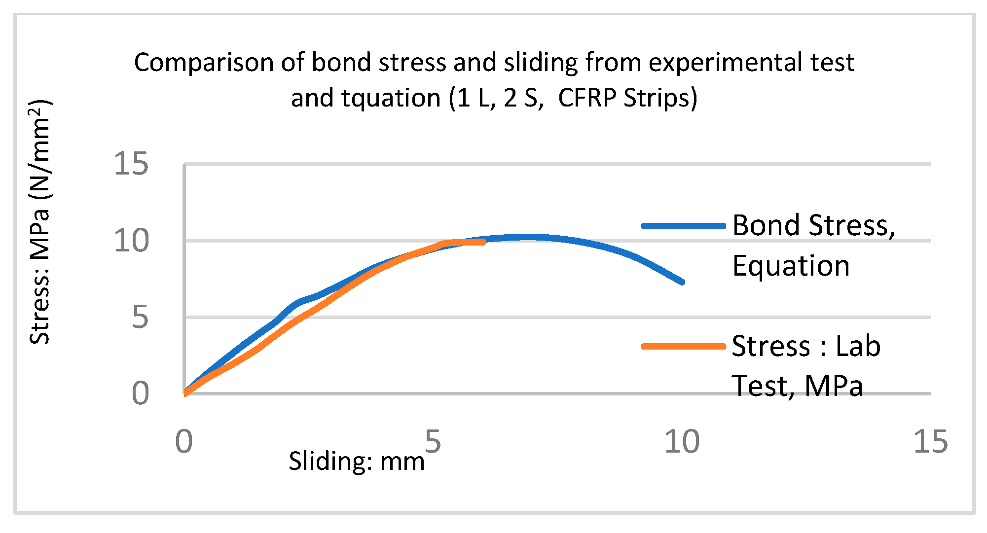
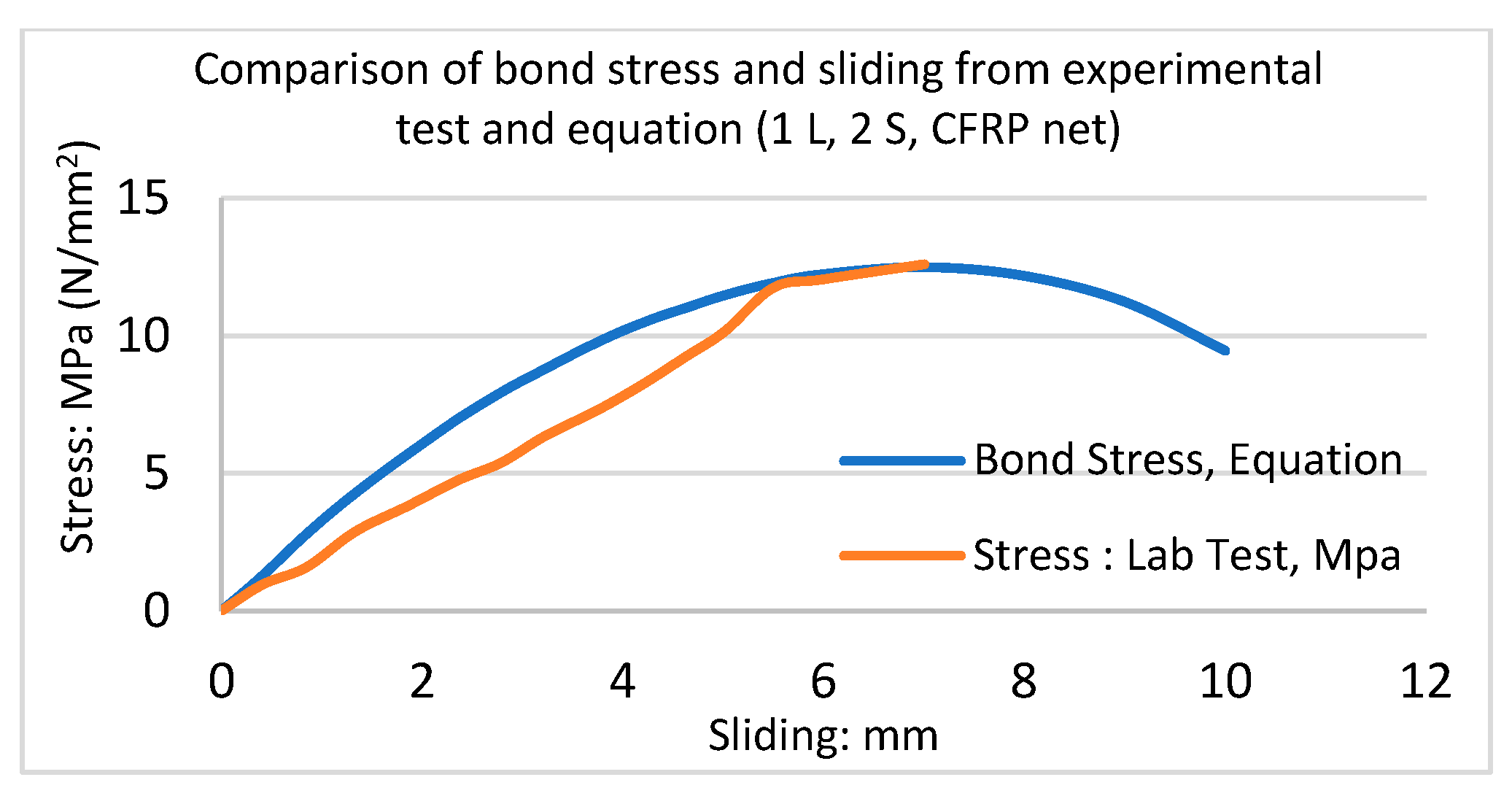
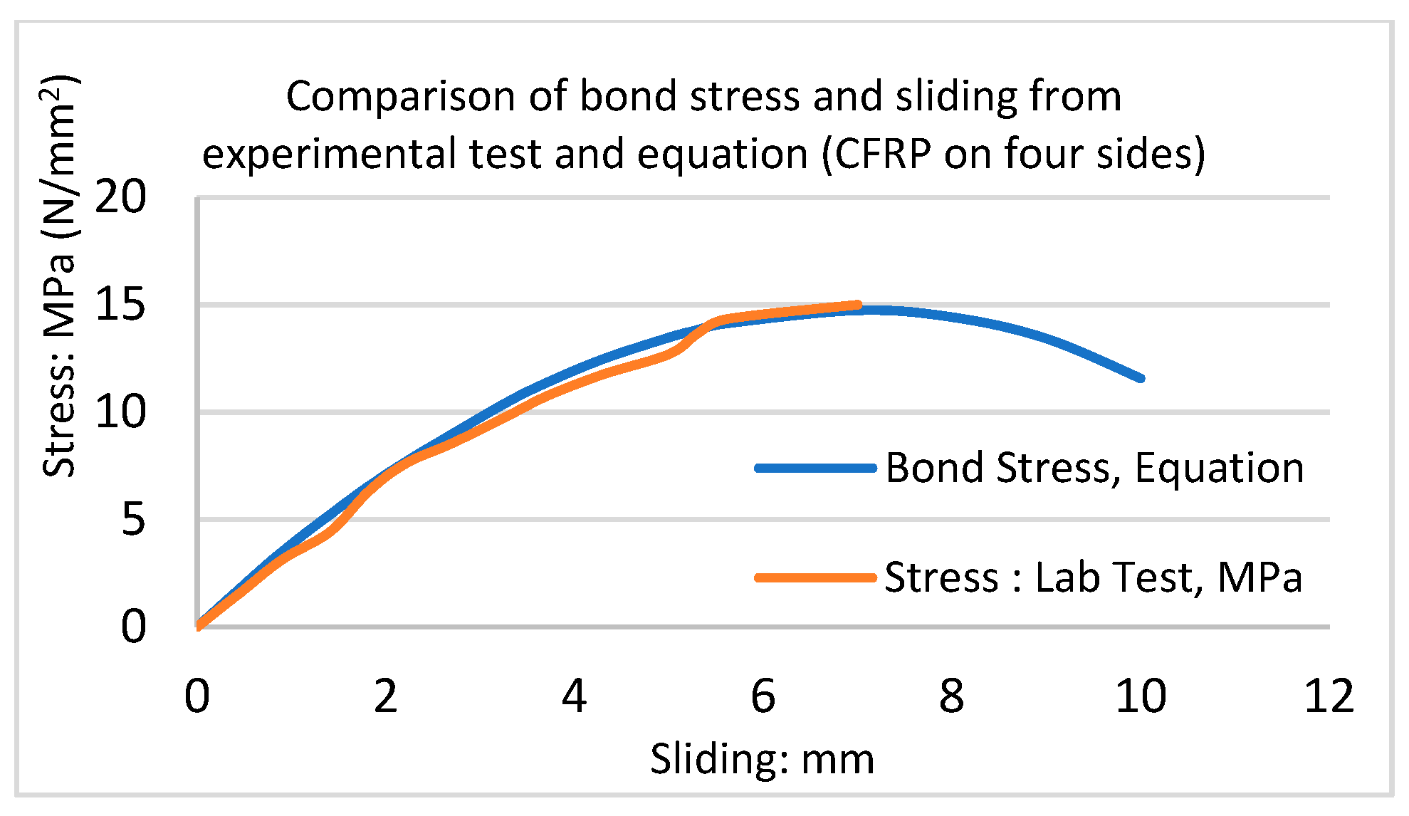
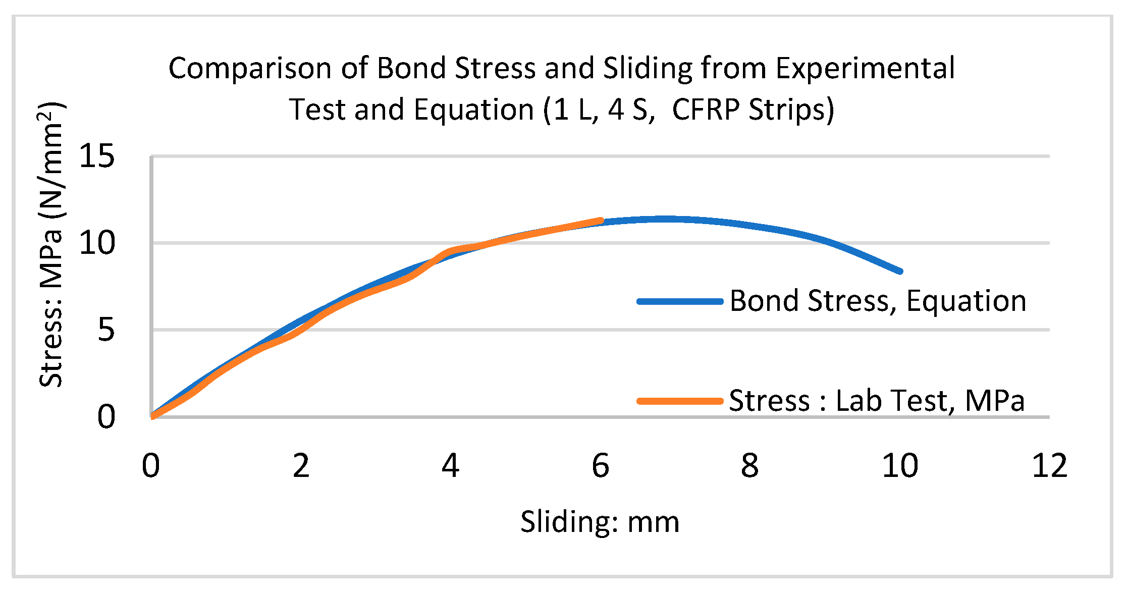
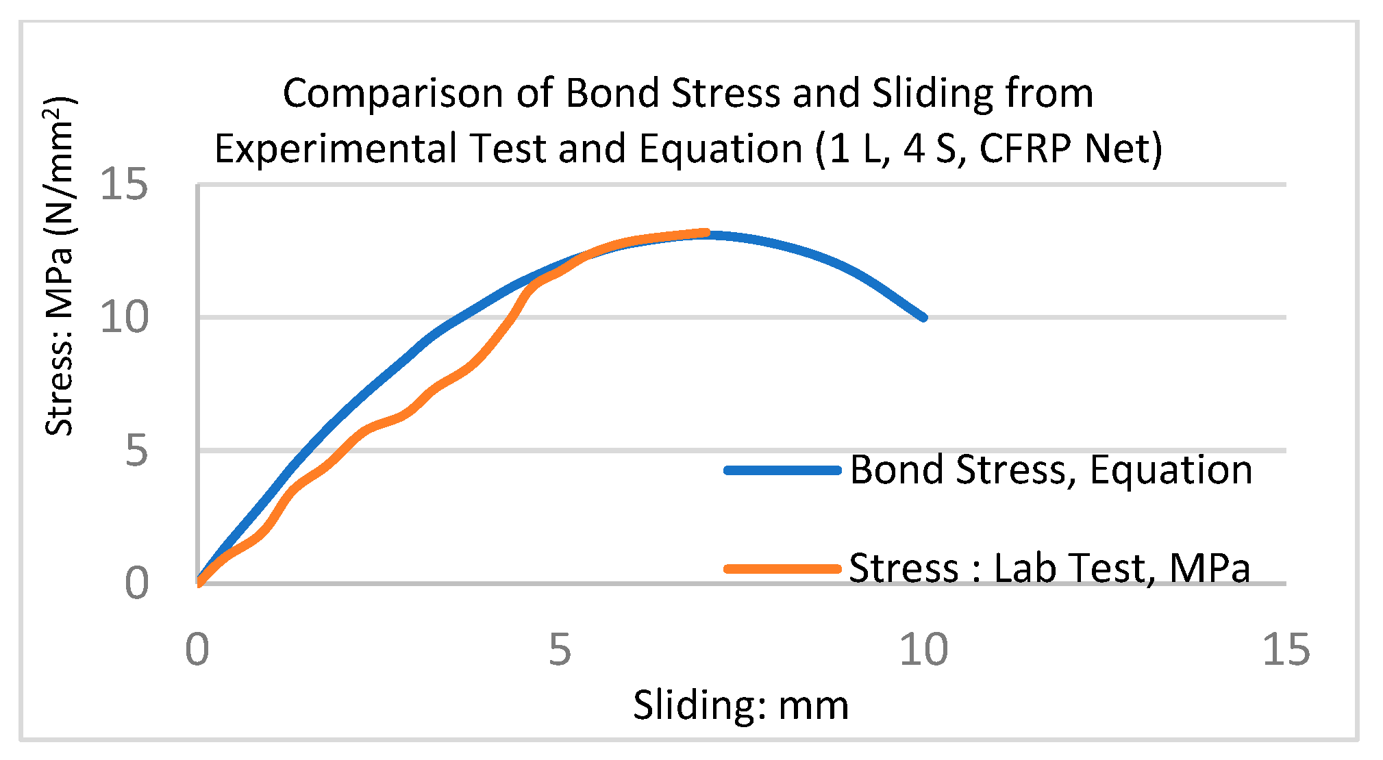
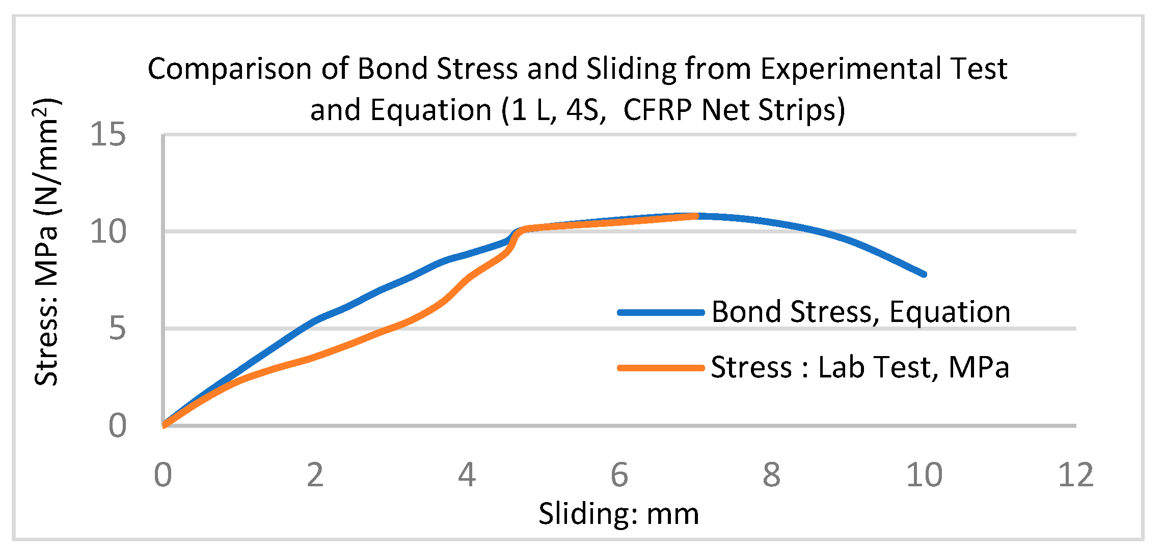
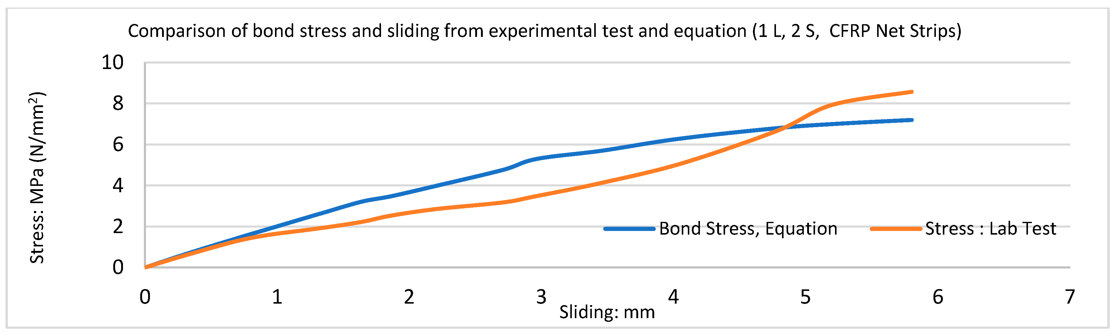
In this study and based on the database of the experimental results, if the sliding/slipping distance is known, the bond stress for all CFRP configurations of triplet masonry can be calculated with the newly developed equations shown in Table 6. Moreover, bond stress can be calculated at any sliding point, and the failure point is predictable. To find a reliable equation, a quadratic formula with a trial-and-error coefficient was used to develop equations that were validated against experimental tests. The bond stresses predicted by the equations were compared with the experimental tests. They are shown in Figure 28, Figure 29, Figure 30, Figure 31, Figure 32, Figure 33, Figure 34, Figure 35 and Figure 36. The bond stress and sliding curves are in good agreement with the experimental results. In all diagrams, L denotes the CFRP layer, and S represents the side of the triplet. By using the new equations, it was possible to predict the correct bond stress at any sliding distance for solid London brick and mortar M4 reinforced with eight different CFRP configurations as well as for unreinforced triplet masonry. The equations in the present study are an advancement directly benefiting engineers in predicting the correct bond stress-slip resistance. (L represents layer, and S denotes side).
5. Finite Element Simulation and Verification via Results from an Experimental Study
The interaction of bricks and mortar is critical in the nonlinear analysis of masonry structures. The use of interface elements in the micro- and simplified micro-models enables the identification and analysis of potential failure mechanisms occurring within the mortar joint. These failure mechanisms encompass brick/mortar decohesion and cracking across the mortar layer. As a result, interface elements have a wide range of applications in the analysis of masonry structures, and ongoing research is being conducted to further their development. Page [34] was the pioneer in endeavouring to incorporate interface elements within masonry walls. D’Altri et al. [35,36] introduced a new 3D micro-model that depicts the response of masonry walls under both in-plane and out-of-plane loading scenarios. This model comprises textured units that are composed of a single brick and mortar layer. To address the limitations of the detailed micro-modelling approach, a simplified micro-modelling technique was developed. The use of simplified micro-modelling is prevalent in the numerical analysis of masonry due to its straightforwardness and substantial decrease in analysis duration in comparison to intricate micro-modelling, as evidenced by various studies, such as those by Doran et al. [37,38,39]. Micro-models, according to Lourenco et al. [40,41,42,43], are probably the best tools available for understanding masonry behaviour. The advantage of using this method is that it takes into account all of the different failure mechanisms, such as (a) cracking and sliding along the bed or head joints, (b) cracking of the units in direct tension, and (c) masonry crushing, which is commonly identified as the splitting of units in tension as a result of mortar at high normal stress values. Ravi et al. [44] carried out a numerical investigation that provided detailed information on masonry behaviour that could be compared to the actual behaviour of masonry structures. Masonry is anisotropic due to the presence of nonlinear and non-homogeneous mortar joints. The finite element method can be used to perform nonlinear analysis of unreinforced brick masonry. Prakash and Alagusundaramoorthy [45] have demonstrated that micro-modelling of triplet masonry is an effective approach to identifying the behaviour and shear transfer mechanism across the mortar joint. The shear transfer mechanisms at joints can be categorized into three types, namely sliding, interlocking, and overriding.
5.1. Modelling by ANSYS and Verification via Experimental Studies
In this study, the shear and bond behaviour of FRP-strengthened triplet masonry was investigated analytically through the use of the commercial software ANSYS versions 18 and 19.2 [46,47]. Different strengthened specimens were analysed, and the behaviour of the samples was compared with results from the experimental studies. The analytical modelling process was based on the following set of assumptions:
- The cross-sectional area and the modulus of elasticity remain unchanged throughout the loading process.
- Masonry samples are regarded as consisting of a material that is both non-homogeneous and isotropic in nature.
Researchers prefer employing homogeneous modelling and linear elastic behaviour in order to simulate masonry walls. However, in this study, non-homogeneous micro-modelling and nonlinear elastic behaviour were assumed for the URM triplets. The compression and shear behaviour of strengthened masonry could be compared together, particularly since the displacement of triplet masonry was one of the main objectives of the present research.
5.2. Formulation of the Model (Micro-Modelling of the Brick Masonry)
Brickwork strength is reliant on the physical features of the masonry unit, the mortar, and the bond among them. In the current study, models with two different materials are presented, which are brick units and mortar joints. The brick unit was modelled using solid 185. Solid 185 is used for the 3-D modelling of structures and is defined by eight nodes. Each node has three degrees of freedom: translations in the nodal x, y, and z directions. The element considers large deflection, large strain, plasticity, creep, and stress stiffening capabilities. Deformations of nearly incompressible elastoplastic materials and fully incompressible hyperelastic materials can also be simulated, as it has mixed formulation capabilities. This is available as a homogenous structural solid element and a layered structural solid element. The mortar joint was modelled using solid 65; solid 65 is used for 3-D modelling of solids with or without reinforcing bars (rebar). Solid 65 is capable of cracking in tension and crushing in compression. The element is defined by eight nodes having three degrees of freedom at each node: translations in the nodal x, y, and z directions. Up to three different rebar specifications may be defined. The most important aspect of this element is the treatment of nonlinear material properties.
To predict the mechanical performance of masonry, finite element models of specimens have been developed. The current study attempted to develop a finite element model to predict the shear strength of masonry prisms subjected to shear loading. The micro-level models consider the units and mortar joints separately. Thus, the structural analysis was performed, taking into consideration each element of the masonry material. The stack-bonded brick masonry prism was built with three solid London clay bricks measuring 220 mm × 104 mm × 65 mm in 10 mm thick cement mortar with a 1:4 (M4) ratio. Separate layers of elements represented the bricks and mortar joints. Each element type was represented by its properties as well as its initial modulus of elasticity. The loading was applied to the model’s top surface. The micro-modelling approach was used to represent brick and mortar joints as continuum elements. The bond between brick and mortar was modelled using contact elements. The constitutive behaviour of the contact elements was based on the aforementioned Equations (6)–(14) given in Table 6.
5.3. CFRP Configurations for Analytical Study by ANSYS
This study on finite element analysis (FEA) provided evidence that the enhancement in resistance to triplet load was a result of the augmentation in fibre-reinforced polymer (FRP) composite material. The experimental results showed that retrofitting CFRP composites increased the load resistance of masonry triplets. CFRP retrofitting increased the strength and deformation capacity of triplets. Until the point of failure, the bond between the CFRP and the triplet surface remained unbroken. In the present investigation, modelling was conducted on triplet specimens to find the strength of the brick masonry. The study also examined the performance of three sets of triplet samples that were retrofitted using various arrangements of CFRP composites. The retrofitted triplets’ test results were used to validate the micro-modelling. The FE modelling consisted of nine different triplet masonry configurations with one-layer CFRP and CFRP net as follows: (1) CFRP on two sides, (2) CFRP on four sides, (3) CFRP strips on two sides, (4) CFRP strips on four sides, (5) CFRP net on two sides, (6) CFRP net on four sides, (7) CFRP net strips on two sides, and (8) CFRP net strips on four sides of triplet masonry and unreinforced triplet masonry (URTM); they were analysed under shear loading.
5.4. Loading, Boundary Conditions, and Load-Deformation Behaviour
It was assumed that an ideal connection existed between the surface of the triplet and the CFRP composite. The load was applied to the upper part of the central brick, while the lower parts of the side bricks were considered to be fixed, allowing no movement in any direction. The software employed a surface-to-surface contact algorithm to simulate the interface between brick and mortar. In this simulation, the brick surface was designated as the target surface owing to its higher modulus of elasticity, while the mortar surface was identified as the contact surface. According to the experimental data, significant stress was transferred to the FRP around the cracked elements, and the CFRP retrofitted triplet exhibited nonlinear load resistance-displacement behaviour. After cracking through the bed joints, the CFRP began to resist the load.
6. Finite Element Analyses for Masonry Triplets with and without CFRP
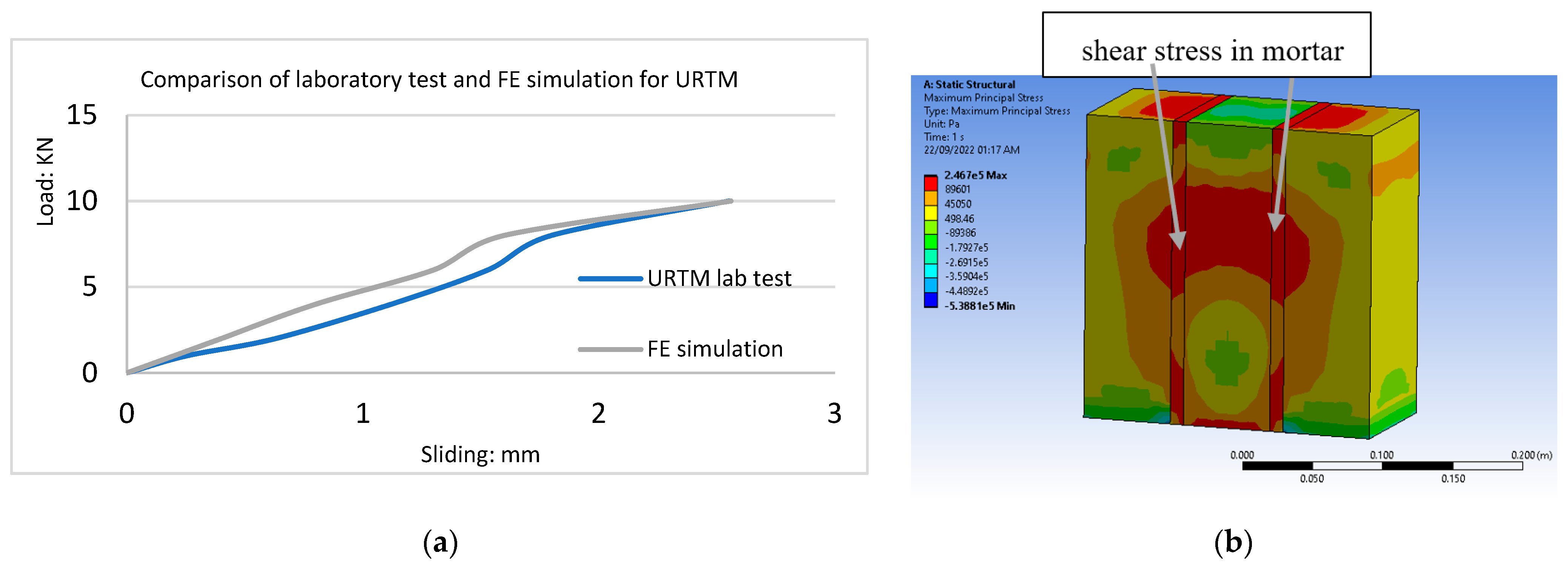
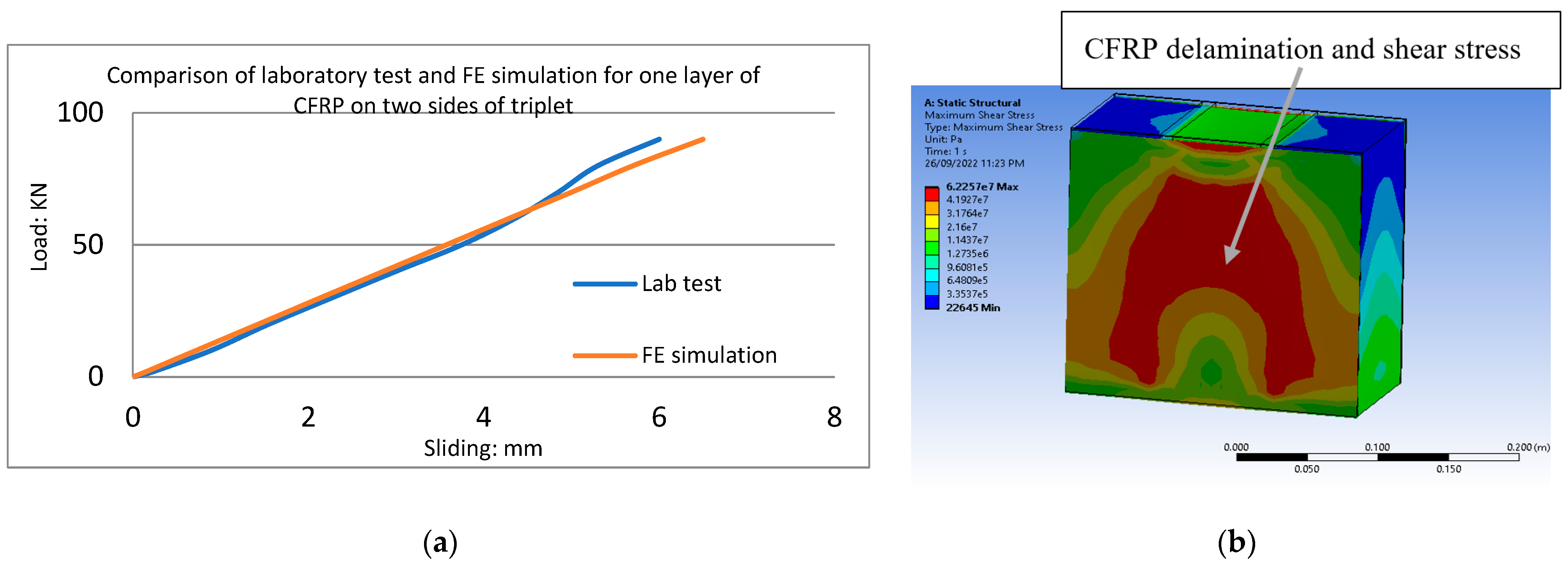
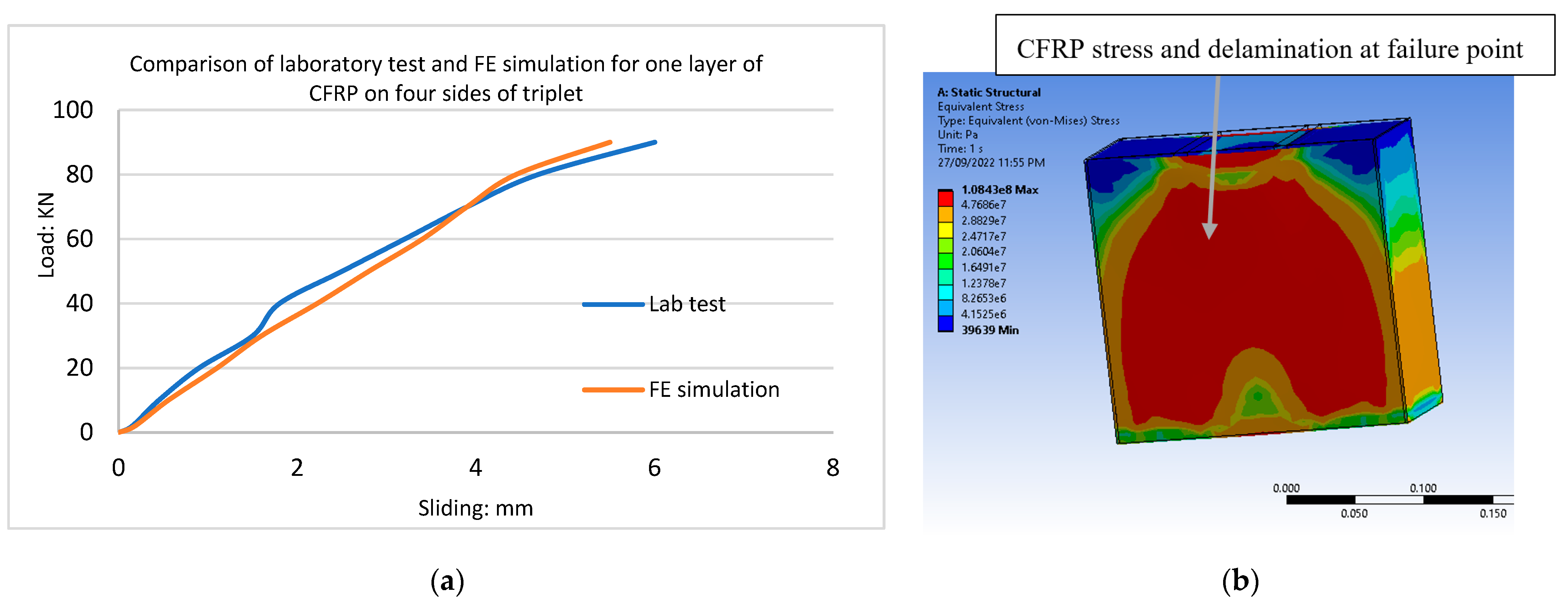
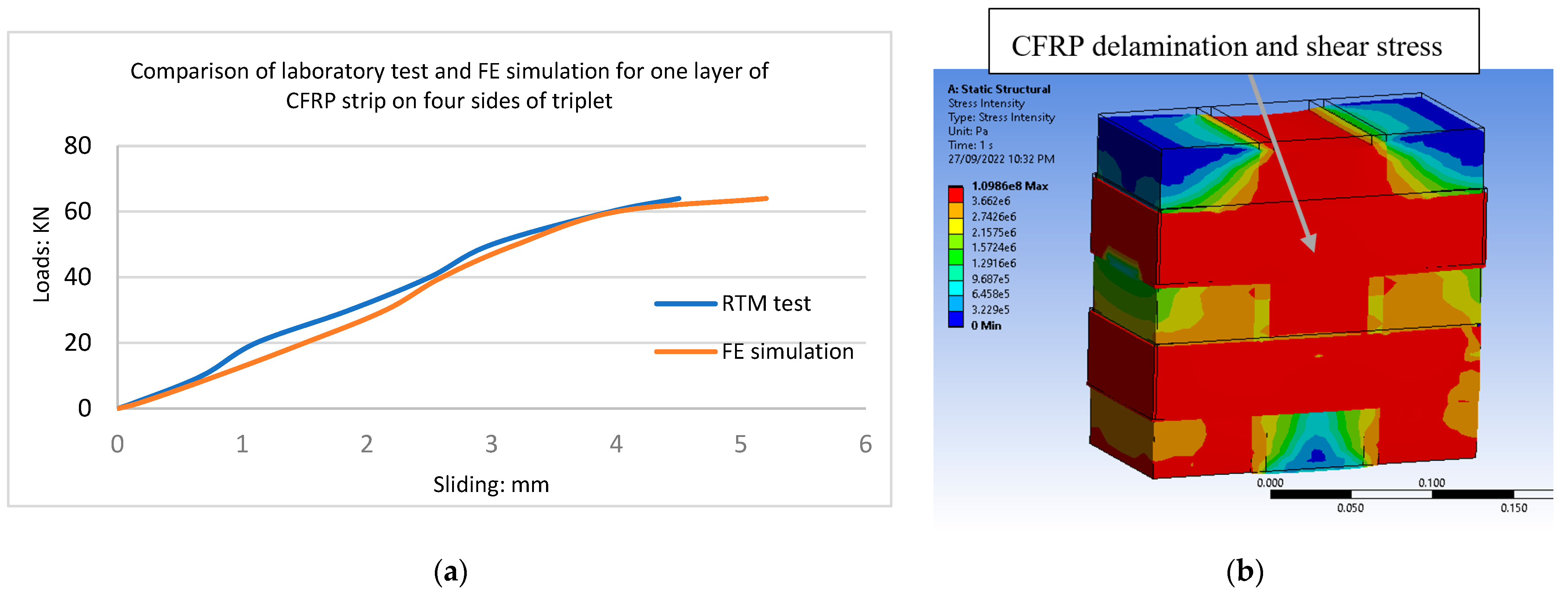
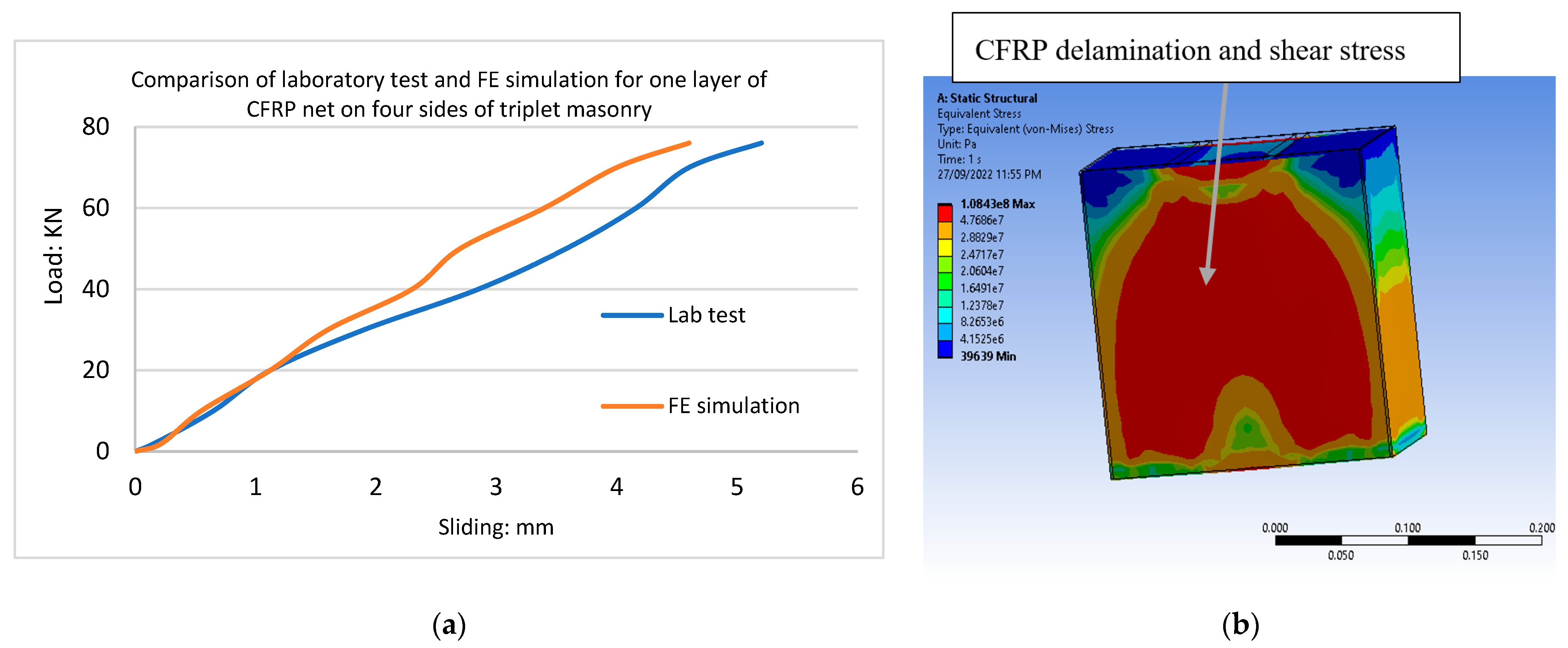
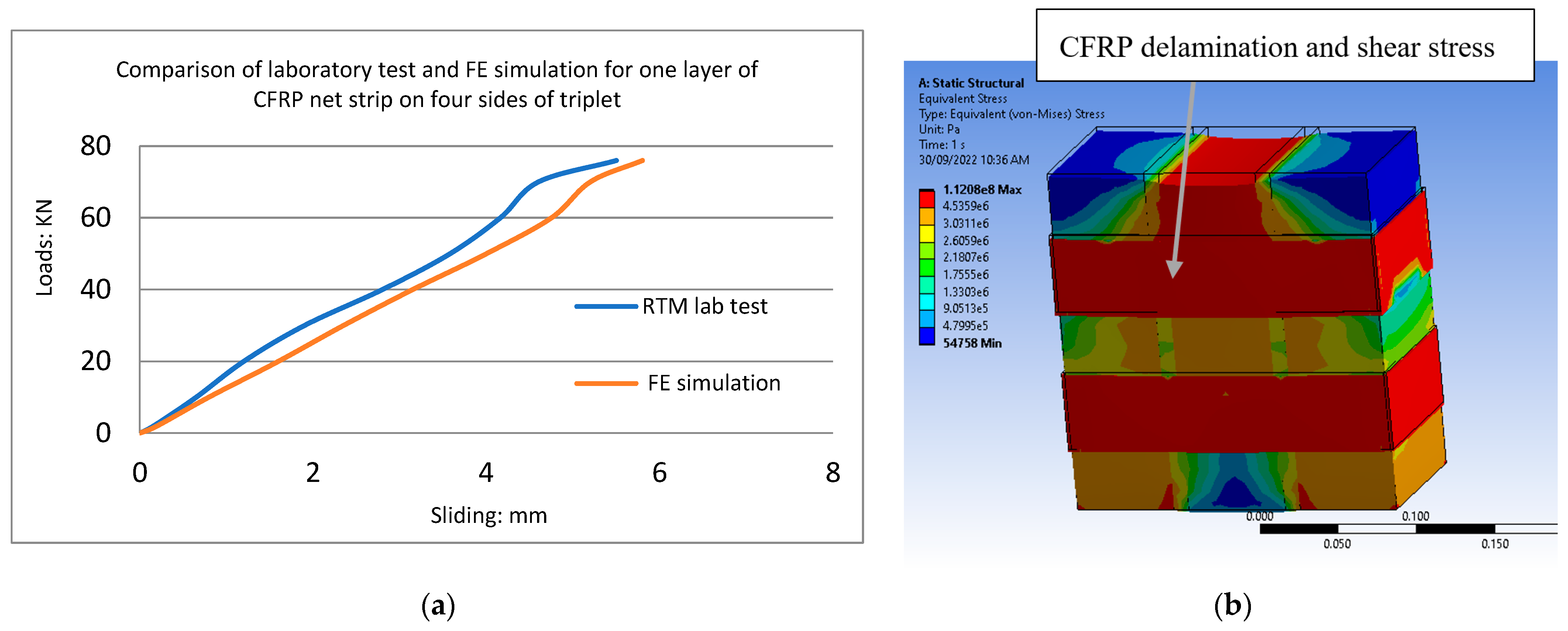
The FE modelling demonstrated that the effect of CFRP increased the load resistance of the samples. The experimental results showed that retrofitting masonry triplets with CFRP composites increased their load resistance. The bricks and mortar were represented as separate elements with their properties using the initial modulus of elasticity from the experimental tests, and the brick and mortar joints were modelled using the micro-modelling approach. Figure 37a, Figure 38a, Figure 39a, Figure 40a, Figure 41a, Figure 42a, Figure 43a, Figure 44a and Figure 45a present a comparison of the experimental tests and developed finite element simulations for all CFRP configurations. Figure 37b, Figure 38b, Figure 39b, Figure 40b, Figure 41b, Figure 42b, Figure 43b, Figure 44b and Figure 45b depict the localized increase in stress at the interfaces of the brick-and-mortar surfaces. The failure started at the peripheral edges of the interface layer, gradually progressing towards the middle of the specimen. The mortar with a lower modulus of elasticity experienced higher stress and cracks compared to the brick. The deformation experienced by the entire mortar was relatively high, pointing towards the possibility of interface delamination. Based on the FE analysis of masonry triplets, it was observed that the stress is effectively transferred to the CFRP composite, leading to a stronger connection between the brick and mortar. As shown in Figure 37b, Figure 38b, Figure 39b, Figure 40b, Figure 41b, Figure 42b, Figure 43b, Figure 44b and Figure 45b, the stress transferred from mortar and bricks to CFRP and the failure of all triplets began in the brick-and-mortar interface layer, sweeping to the CFRP on the specimen. The cracks observed in both the mortar layer and the brick during the experimental test were similar to the ones anticipated by the suggested model. In experimental tests and also in finite element analyses, the debonding of CFRP from triplets was the main reason for failure; the loss of bonding between the reinforcement composite and masonry interface is primarily responsible for the occurrence of this failure. The occurrence of failure indicated that the crack originated from the separation of the masonry units from the mortar and propagated across the entire thickness until there was the detachment of the epoxy and CFRP from the masonry units. At this point, the triplet failed because the tensile stresses were no longer transferred to the CFRP, confirming that the developed numerical model can simulate the failure modes of triplets with sufficient accuracy.
The ultimate displacement predicted by the numerical modelling for all CFRP configurations on triplet masonry was much lower compared with the results obtained in the experimental test. It is normal to find disagreement between analytical finite element modelling and experimental tests. In this study, the comparison of the load-displacement graphs from the theoretical modelling with the results from the experimental tests showed significantly low displacement and were not accurate, thus the user-defined functions for finite element modelling were developed.
The reason for lower sliding in FE modelling than in the experimental tests is that the finite element program in Ansys assumes a perfect bond between brick and mortar. The perfect homogeneous material is the other assumption in finite element analysis. Therefore, this error can be corrected by using the developed functions in Table 6 as a user-defined function (UDF) to create correct sliding and 3D modelling for eight CFRP configurations. By using the UDF functions, it is possible to predict correct sliding in 3D modelling at any load or stress point. The FEM stress in mortar and sliding of the middle brick in this study is similar to the results obtained by Hernoune, et al. [18].
According to the diagrams from the FE modelling, interface stresses and sliding failure propagation initiated at the brick-and-mortar interface layer spread to the CFRP and brick interface on the specimens. The failure of interface elements commenced at the middle brick interfaces, which might have been due to the boundary conditions on the left and right ends of the specimen’s outer bricks and the direction of loading. Full cracking was only observed at the inner interfaces, starting at the maximum load.
7. Discussion and Conclusions
Overall, reinforced triplet masonry shear tests play a significant role in ensuring the safety, reliability, and longevity of masonry constructions by providing valuable insights into the behaviour of materials under shear stress. Engineers and construction professionals can use the test results to select the most effective reinforcement method for masonry walls in earthquake-prone regions. The findings can influence building codes and construction practices to enhance the seismic resilience of structures.
In the strengthened triplets, the failure was caused by the loss of bonding between the CFRP and the masonry units. The mode of failure for all configurations was ductile, and delamination occurred just before failure. FRP ruptured at mid-span, followed by shearing of the sheets in the middle of the sample being observed. It was also observed that the presence of the CFRP improved the triplets’ performance by changing the failure from brittle to ductile.
In summary, the experimental data yielded the following observations:
- All types of reinforced triplets increased bond strength by up to four to six times compared with triplets without CFRP, and the extent of reinforcement effectiveness varied based on the configuration employed.
- The shear failure of brickwork commenced with cracking and sliding through the mortar joints. The failure occurred along the interface between the brick-and-mortar joints.
- The highest ductility in terms of maximum sliding at the ultimate load was observed for all samples.
- The retrofitting of shear triplets with CFRP composites reduced the interfacial shear stress concentrations between the brick-and-mortar surfaces, and in contrast with URM triplets, the strengthened samples were stable after failure.
- The bond strength in reinforced triplets with the same amount of CFRP and CFRP net was found to be almost equal. The main reason for this could be comparable values of the modulus of elasticity.
- A debonding failure pattern was observed in reinforced triplets with CFRP sheet and CFRP strip configurations.
- Comparison of the finite element analyses using the newly developed equations with experimental tests for reinforced triplet masonry with different CFRP configurations showed good agreement, resulting in a high level of accuracy.
8. Suggestions for Further Investigations
The effectiveness of the FRP composites for reinforcement of the masonry structures has been proven in this study, but further investigations are needed to clarify the behaviour of FRP-strengthened masonry walls. Some of the areas that need to be investigated are indicated below:
- Further information about the durability of composite materials used in the reinforcement of URM walls under different environmental conditions would be very beneficial.
- Investigation of surface preparation methods and the amount of impregnating resins are also needed.
- An investigation of the coupled behaviour of compression forces and FRP strengthening of masonry specimens is needed.
- Since debonding of FRP from the masonry surface is the main reason for failure and has a direct relationship with the porosity of the masonry unit and mortar, the different types of masonry units and mortar should be investigated.
- A numerical investigation of the different parameters affecting the behaviour (e.g., masonry properties, CFRP properties, and thickness) needs to be performed.
- Investigation of strengthened masonry specimens under high temperatures.
- Investigation of large-scale strengthened masonry walls with different CFRP configurations under combinations of in-plane and out-of-plane loadings.
Author Contributions
Conceptualization, methodology, software, validation, formal analysis, investigation, data curation and writing—original draft preparation, S.M.H.; supervision, project administration, writing—review and editing, A.A. All authors have read and agreed to the published version of the manuscript.
Funding
This research did not receive any specific grant from funding agencies in the public, commercial, or not-for-profit sectors.
Data Availability Statement
Data are contained within the article.
Acknowledgments
The authors are grateful for the support of the technical staff of the structural laboratory at City, University of London, in particular to the Brett McKinley.
Conflicts of Interest
The authors declare no conflict of interest.
References
- Ehsani, M.R.; Saadatmanesh, H. Shear behaviour of URM retrofitted with FRP Overlays. J. Compos. Constr. 1997, 1, 17–25. [Google Scholar] [CrossRef]
- Ehsani, M. Strengthening of Concrete and Masonry Structures with Fiber Reinforced Polymers (FRP). In Proceedings of the 30th Conference on Our World in Concrete & Structures, Singapore, 23–24 August 2005. [Google Scholar]
- Saadatmanesh, H. Extending service life of concrete and masonry structures with fibre composites. Constr. Build. Mater. 1997, 11, 327–335. [Google Scholar] [CrossRef]
- Ferretti, F.; Ferracuti, B.; Mazzotti, C.; Savoia, M. Destructive and minor destructive tests on masonry buildings: Experimental results and comparison between shear failure criteria. Constr. Build. Mater. 2019, 199, 12–29. [Google Scholar] [CrossRef]
- Ehsani, M.; Saadatmanesh, H. Fibre Composites: An Economical Alternative for Retrofitting Earthquake-Damaged Precast-Concrete Walls. Earthq. Spectra 1997, 13, 225–241. [Google Scholar] [CrossRef]
- Mohammadipour, A.; Willam, K. Lattice simulations for evaluating interface fracture of masonry composites. Theor. Appl. Fract. Mech. 2016, 82, 152–168. [Google Scholar] [CrossRef]
- Pavan, G.S.; Nanjunda Rao, K.S. The behaviour of Brick–Mortar Interfaces in FRP-Strengthened Masonry Assemblages under Normal Loading and Shear Loading. Am. Soc. Civ. Eng. 2015, 28, 04015120. [Google Scholar] [CrossRef]
- Tumialan, G.J.; Nanni, A. In-Plane and Out-of-Plane Behaviour of Masonry Walls Strengthened with FRP Systems; Department of Civil Engineering, University of Missouri: Rolla, MO, USA, 2001. [Google Scholar]
- Tumialan, G.; Micelli, F.; Nanni, A. A Structural Engineering Odyssey. In Proceedings of Structures Congress & Exposition; Chang, P.C., Ed.; ASCE: New York, NY, USA, 2001. [Google Scholar]
- Tumialan, G.; Vatovec, M.; Kelley, P.L. FRP Composites for Masonry Retrofitting. Structure Magazine, 12 May 2009; pp. 12–14. Available online: https://www.structuremag.org/wp-content/uploads/2014/08/C-BuildingBlocks-Tumialan-May091.pdf (accessed on 8 January 2024).
- Tumialan, J.G. In-Plane and Out-of-Plane Behaviour of Masonry Walls Strengthened with FRP Systems; CIES Research Report; University of Missouri: Rolla, MO, USA, 2003; pp. 1–4. [Google Scholar]
- El Malyh, S.; Bouyahyaoui1, A.; Cherradi1, T.; Rotaru, A.; Mihai, P. In-Plane Shear Behaviour of Unreinforced Masonry Walls Strengthened with Fibre Reinforced Polymer Composites. Advances in Science. Technol. Eng. Syst. J. 2020, 5, 360–367. [Google Scholar]
- ASTM E-519-02; Standard Test Method for Diagonal Tension (Shear) in Masonry Assemblages. ASTM International: West Conshohocken, PA, USA, 2002.
- Babatunde, S.A. Review of strengthening techniques for masonry using fibre reinforced polymers. Compos. Struct. 2017, 161, 246–255. [Google Scholar] [CrossRef]
- Hamrat, M.; Bouziadi, F.; Boulekbache, B.; Daouadji, T.H.; Chergui, S.; Labed, A.; Amziane, S. Experimental and Numerical investigation on the deflection behaviour of pre-cracked and repaired reinforced concrete beams with fibre-reinforced polymer. Constr. Build. Mater. 2020, 249, 118745. [Google Scholar] [CrossRef]
- Luccioni, B.; Rougier, V.C. In-plane retrofitting of masonry panels with fibre reinforced composite materials. Constr. Build. Mater. 2010, 25, 1772–1788. [Google Scholar] [CrossRef]
- Luccioni, B.; Rougier, V.C. Shear behaviour of brick–mortar interface in CFRP retrofitted or repaired the masonry. Int. J. Mech. Sci. 2010, 52, 602–611. [Google Scholar] [CrossRef]
- Hernoune, H.; Benabed, B.; Abousnina, R.; Alajmi, A.; Alfadhili, A.M.G.; Shalwan, A. Experimental Research and Numerical Analysis of CFRP Retrofitted Masonry Triplets under Shear Loading. Polymers 2022, 14, 3707. [Google Scholar] [CrossRef]
- Hamid, A.A.; El-Dakhakhni, W.W.; Hakam, Z.H.; Elgaaly, M. Behavior of composite unreinforced masonry– fiber-reinforced polymer wall assemblages under in-plane loading. J. Compos. Constr. 2005, 9, 73–83. [Google Scholar] [CrossRef]
- Saingam, P.; Hlaing, H.H.; Suwannatrai, R.; Ejaz, A.; Hussain, Q.; Khan, K.; Joyklad, P. Enhancing the flexural behavior of brick masonry walls with ferrocement overlays and low-cost anchors. Case Stud. Constr. Mater. 2023, 19, e02558. [Google Scholar] [CrossRef]
- Joyklad, P.; Hussain, Q. Development of strength models for brick walls: Experimental and theoretical study. Results Eng. 2023, 18, 101103. [Google Scholar] [CrossRef]
- Rashid, A.S.A.; Shirazi, M.G.; Mohamad, H.; Sahdi, F. Bearing capacity of sandy soil treated by Kenaf fibre geotextile. Environ. Earth Sci. 2017, 76, 431. [Google Scholar] [CrossRef]
- Saidi, T.; Hasan, M.; Amalia, Z.; Salsabila, S. The analysis of the bond strength between natural fiber reinforced polymer (NFRP) sheets and concrete. Result Eng. 2023, 18, 101124. [Google Scholar] [CrossRef]
- Amalia, Z.; Hasan, M.; Saidi, T.; Nadia, S. Bonding Behavior of Pineapple and Silk Fiber-based NFRP on Strenghthened Reinforced Concrete Beams Using Direct Tensile Test. AIP. Conf. Proc. 2023, 2711, 060005. [Google Scholar] [CrossRef]
- EN 998-2; Specification for Mortar for Masonry-Part 2: Masonry Mortar. European Committee for Standardization: Brussels, Belgium, 2003.
- Rahman, A.; Ueda, T. In-Plane shear performance of masonry walls after strengthening by two different FRPs. J. Compos. Constr. 2016, 20, 04016019. [Google Scholar] [CrossRef]
- Stefano, S. Masonry Reinforced with FRP. In Centre for Infrastructure Engineering Studies (CIES); University of Missouri, Engineering Research Lab: Rolla, MO, USA; Available online: https://quakewrap.com/frp%20papers/MasonryReinforcedwithFRPSystems.pdf (accessed on 8 January 2024).
- Derias, M.; El-Hacha, R. Flexural and Shear Strengthening of Masonry Walls with FRP Composite Materials. In Proceedings of the 2007 International Institute for FRP in Construction, Hong Kong, China, 12–14 December 2007. [Google Scholar]
- Zimmermann, T.; Strauss, A.; Bergmeister, K. Structural Behaviour of Low- and Normal-Strength Interface Mortar of Masonry. 8 November 2011. Available online: https://www.researchgate.net/publication/257896156_Structural_behavior_of_low_and_normalstrength_interface_mortar_of_masonry (accessed on 8 November 2011).
- EN 1052-3; Methods of Test for Masonry–Part 3: Determination of Initial Shear Strength. European Committee for Standardization: Brussels, Belgium, 2007.
- Mojsilovi’c, N. Masonry elements with damp-proof course membrane: Assessment of shear strength parameters. Constr. Build. Mater. 2012, 35, 1002–1012. [Google Scholar] [CrossRef]
- Prakash, S.S.; Alagusundaramoorthy, P. Load resistance of masonry wallets and shear triplets retrofitted with GFRP composites. Cem. Concr. Compos. 2007, 30, 745–761. [Google Scholar] [CrossRef]
- Bompa, D.; Elghazouli, A. Experimental and numerical assessment of the shear behaviour of lime mortar clay brick masonry triplets. Constr. Build. Materials. Constr. Build. Mater. 2020, 262, 120571. [Google Scholar] [CrossRef]
- Page, A.W. Finite element model for masonry. J. Struc. Div. ASCE 1978, 104, 1267–1285. [Google Scholar] [CrossRef]
- D’Altri, A.M.; de Miranda, S.; Castellazzi, G.; Sarhosis, V. A 3D detailed micro-model for the in-plane and out-of-plane numerical analysis of masonry panels. Comput. Struct. 2018, 206, 18–30. [Google Scholar] [CrossRef]
- D’Altri, A.M.; Sarhosis, V.; Milani, G.; Rots, J.; Cattari, S.; Lagomarsino, S.; Sacco, E.; Tralli, A.; Castellazzi, G.; de Miranda, S. Modeling strategies for the computational analysis of unreinforced masonry structures: Review and classification. Arch. Comput. Methods Eng. 2020, 27, 1153–1185. [Google Scholar] [CrossRef]
- Doran, B.; Koksal, H.O.; Aktan, S.; Ulukaya, S.; Oktay, D.; Yuzer, N. In-plane shear behaviour of traditional masonry walls. Int. J. Archit. Herit. 2017, 11, 278–291. [Google Scholar] [CrossRef]
- Doran, B.; Yuzer, N.; Aktan, S.; Oktay, D.; Ulukaya, S. Numerical modelling of traditional masonry walls strengthened with grout injection. Int. J. Archit. Herit. 2020, 14, 1517–1532. [Google Scholar] [CrossRef]
- Doran, B.; Karslioglu, M.; Unsal Aslan, Z.; Vatansever, C. Experimental and Numerical Investigation of Unreinforced Masonry Walls with and without Opening. Int. J. Archit. Herit. 2022, 17, 1833–1854. [Google Scholar] [CrossRef]
- Lourenço, P.B.; Barros, J.O.; Oliveira, J.T. Shear testing of stack bonded masonry. Constr. Build. Mater. 2004, 18, 125–132. [Google Scholar] [CrossRef]
- Lourenço, P.B. Multisurface interface model for analysis of masonry structures. J. Eng. Mech. 1997, 123, 660–668. [Google Scholar] [CrossRef]
- Lourenço, P.B.; De Borst, R.; Rots, J.G. A plane stress softening plasticity model for orthotropic materials. Int. J. Numer. Methods Eng. 1997, 40, 4033–4057. [Google Scholar] [CrossRef]
- Lourenço, P.B.; Rots, J.; Blaauwendraad, J. Continuum model for masonry: Parameter estimation and validation. J. Struct. Eng. 1998, 124, 642–652. [Google Scholar] [CrossRef]
- Ravi1, S.; Viswanathan, S.; Nagarajan, T.; Srinivas, V.; Narayanan, P. Experimental and Numerical Investigations on Material Behaviour of Brick Masonry. In Proceedings of the 2nd International Conference on Research in Science, Engineering and Technology (ICRSET), Paris, France, 22–24 November 2019. [Google Scholar]
- Prakash, S.S.; Alagusundaramoorthy, P. Study on Brick Masonry Infill Walls with Air Gap. In Proceedings of the Ninth Canadian Conference on Earthquake Engineering, Ottawa, ON, Canada, 26–29 June 2007. [Google Scholar]
- ANSYS Inc. ANSYS User Manuals: Released 18.0; ANSYS Inc.: Canonsburg, PA, USA, January 2017; Available online: https://users.abo.fi/rzevenho/ansys%20fluent%2018%20tutorial%20guide.pdf (accessed on 8 January 2024).
- ANSYS User Manual. Element Reference and Structural Analysis Guide, Release 19.2. August 2018. Available online: https://forum.ansys.com/uploads/534/5I3WFK94SATN.pdf (accessed on 8 January 2024).
Figure 1.
CFRP.

Figure 2.
Resin.

Figure 3.
Masonry triplets before test (A), and Masonry triplets after compression tests (B,C).

Figure 4.
Compression tests on bricks after tests (A,B).

Figure 5.
Compression tests on mortar before test (A), and after failure (B).

Figure 6.
Comparison of elastic modulus for mortar, brick, and triplet masonry samples.

Figure 7.
Comparison of stress-strain curves for mortar, brick, and URM samples.

Figure 8.
Modelling for shear analyses: (A) reinforced masonry prism (cover with CFRP on two sides), (B) reinforced masonry prism with two vertical CFRP on two sides, and (C) unreinforced masonry prism.
Figure 8.
Modelling for shear analyses: (A) reinforced masonry prism (cover with CFRP on two sides), (B) reinforced masonry prism with two vertical CFRP on two sides, and (C) unreinforced masonry prism.

Figure 9.
The failure (cracking) in the mortar joints (A,B).

Figure 10.
Stress-strain curve for the pre-compression test on URTM.

Figure 11.
CFRP on two sides.

Figure 12.
Stress-slip curve for CFRP on two sides.

Figure 13.
CFRP net on two sides.

Figure 14.
Stress-slip curve for strengthening with CFRP net on two sides.

Figure 15.
CFRP strips on two sides.

Figure 16.
Stress-slip curve for strengthening with CFRP strips on two sides.

Figure 17.
CFRP net strips on two sides.

Figure 18.
Stress-slip curve with CFRP net strips on two sides.

Figure 19.
Strengthening with CFRP wrapping on four sides.

Figure 20.
Stress-slip curve for strengthening with CFRP on four sides.

Figure 21.
CFRP net on four sides.

Figure 22.
Stress-slip curve for CFRP net on four sides of a triplet.

Figure 23.
CFRP strips on four sides.

Figure 24.
Stress-slip curve for a triplet with one layer of CFRP strip on four sides.

Figure 25.
CFRP net strips on four sides.

Figure 26.
Stress-slip curve of CFRP net strips on four sides.

Figure 27.
Comparison between results from EN 1052-3:2002 [30], the experimental test, and the new equation (URTM).
Figure 27.
Comparison between results from EN 1052-3:2002 [30], the experimental test, and the new equation (URTM).

Figure 28.
Comparison of bond stress and sliding of URTM (equation and test).

Figure 29.
Comparison of bond stress and sliding from the experimental test and equation (CFRP on two sides).
Figure 29.
Comparison of bond stress and sliding from the experimental test and equation (CFRP on two sides).

Figure 30.
Bond stress and sliding from the experimental test and equation (1 L, 2 S, and CFRP strips).
Figure 30.
Bond stress and sliding from the experimental test and equation (1 L, 2 S, and CFRP strips).

Figure 31.
Comparison of bond stress and sliding from the experimental test and equation (1 L, 2 S, and CFRP net).
Figure 31.
Comparison of bond stress and sliding from the experimental test and equation (1 L, 2 S, and CFRP net).

Figure 32.
Comparison of bond stress and sliding from the experimental test and equation (CFRP on four sides).
Figure 32.
Comparison of bond stress and sliding from the experimental test and equation (CFRP on four sides).

Figure 33.
Comparison of bond stress and sliding from the experimental test and equation (1 L, 4 S, and CFRP strips).
Figure 33.
Comparison of bond stress and sliding from the experimental test and equation (1 L, 4 S, and CFRP strips).

Figure 34.
Comparison of bond stress and sliding from the experimental test and equation (1 L, 4 S, and CFRP net).
Figure 34.
Comparison of bond stress and sliding from the experimental test and equation (1 L, 4 S, and CFRP net).

Figure 35.
Comparison of bond stress and sliding from the experimental test and equation (1 L, 4 S, and CFRP net strips).
Figure 35.
Comparison of bond stress and sliding from the experimental test and equation (1 L, 4 S, and CFRP net strips).

Figure 36.
Comparison of bond stress and sliding from the experimental test and equation (1 L, 2 S, and CFRP net strips).
Figure 36.
Comparison of bond stress and sliding from the experimental test and equation (1 L, 2 S, and CFRP net strips).

Figure 37.
(a) Comparison of laboratory test and FE simulation. (b) Stress in FE simulation.

Figure 38.
(a) Comparison of laboratory test FE simulation. (b) Shear stress at the failure point.

Figure 39.
(a) Comparison of laboratory test and FE simulation. (b) Shear stress at the failure point.
Figure 39.
(a) Comparison of laboratory test and FE simulation. (b) Shear stress at the failure point.

Figure 40.
(a) Comparison of laboratory test and FE simulation. (b) Shear stress in FE simulation.

Figure 41.
(a) Comparison of laboratory test and FE simulation. (b) Shear stress at the failure point.
Figure 41.
(a) Comparison of laboratory test and FE simulation. (b) Shear stress at the failure point.

Figure 42.
(a) Comparison of lab test FE simulation (b) Shear stress at the failure point.

Figure 43.
(a) Comparison of laboratory test and FE simulation. (b) Shear stress in FE simulation.

Figure 44.
(a) Comparison of laboratory test and FE simulation. (b) Shear stress at the failure point.
Figure 44.
(a) Comparison of laboratory test and FE simulation. (b) Shear stress at the failure point.

Figure 45.
(a) Comparison of laboratory test and FE simulation. (b) Shear stress at the failure point.
Figure 45.
(a) Comparison of laboratory test and FE simulation. (b) Shear stress at the failure point.


Table 1.
The characteristics of CFRP.
| CFRP technical data | C-Sheet 240 | ||
| Tensile strength | 4700 MPa | ||
| Elongation | 2% | ||
| E-modulus | 240 GPa | ||
| Thickness, mm | 0.22–0.35 | ||
| Weight, g/m2 | 300 | 400 | 600 |
| Standard width, cm | 20 | 30 | 50 |
| Standard length of rolls, m | 50 | 50 | 50 |
Table 2.
The characteristics of resin.
| Technical data | Type 70–75 |
| Sp. Gr | 1.2 gr/cm3 |
| Hardening starts at 20 °C | 6/7 h |
| Hardening completes at 20 °C | 7 h |
| Resistance to compressive stress | 83 MPa |
| Resistance flexural/tensile stress | 45 MPa |
| Adhesion to concrete | >2.5 MPa |
| Minimum temperature for use | ≥10 °C |
Table 3.
Comparison of bond stress and sliding from the experimental test.
| No | CFRP Configurations on Triplet Masonry (One Layer) | Load: KN | Stress: MPa | Maximum Sliding in Experimental Tests at Failure Point: mm |
|---|---|---|---|---|
| 1 | URTM | 10 | 1.59 | 2.5 |
| 2 | CFRP on two sides | 90 | 14.33 | 6.2 |
| 3 | CFRP on four sides | 90 | 14.33 | 5.6 |
| 4 | CFRP strips on two sides | 62 | 9.85 | 5.3 |
| 5 | CFRP strips on four sides | 62 | 9.85 | 4.4 |
| 6 | CFRP net on two sides | 76 | 12.06 | 6 |
| 7 | CFRP net on four sides | 78 | 12.38 | 5.4 |
| 8 | CFRP net strips on two sides | 54 | 8.57 | 5.8 |
| 9 | CFRP net strips on four sides | 64 | 10.16 | 5.2 |
Table 4.
Comparison of the experimental shear tests and the results from Equations (2) and (3) and EN 1052-3:200 [30].
Table 4.
Comparison of the experimental shear tests and the results from Equations (2) and (3) and EN 1052-3:200 [30].
| Test | Maximum Load: KN | (MPa) EN 1052-3:2002 | (MPa) New Equation | Experimental Shear Tests (MPa) |
|---|---|---|---|---|
| 1 | 4 | 0.087 | 0.612 | 0.64 |
| 2 | 6 | 0.13 | 0.918 | 0.95 |
| 3 | 8 | 0.18 | 1.23 | 1.27 |
| 4 | 10 | 0.22 | 1.53 | 1.59 |
| 5 | 12 | 0.26 | 1.84 | 1.88 |
| 6 | 14 | 0.31 | 2.1 | 2.15 |
Table 5.
Comparison of the shear strength of different configurations of experimental triplets with CFRP and results from the new equation.
Table 5.
Comparison of the shear strength of different configurations of experimental triplets with CFRP and results from the new equation.
| Test | CFRP Configurations on Triplet Masonry | Af/At | Sfrp = σfrp × Af/At × K × μf Sm = Sm0 + Sfrp (MPa) | Experimental Shear Tests (MPa) | Error % |
|---|---|---|---|---|---|
| 1 | One-layer CFRP on two sides | 0.51 | 14.10 | 14.33 | 2 |
| 2 | One-layer CFRP on four sides | 0.75 | 14.45 | 14.33 | 1 |
| 3 | One-layer CFRP strips on two sides | 0.23 | 7.3 | 9.53 | 25 |
| 4 | One-layer CFRP strips on four sides | 0.35 | 10.1 | 9.53 | 6 |
| 5 | One-layer CFRP net on two sides | 0.51 | 14 | 11.75 | 16 |
| 6 | One-layer CFRP net on four sides | 0.75 | 14.45 | 12.06 | 17 |
| 7 | One-layer CFRP net strips on two sides | 0.23 | 7.3 | 8.57 | 17 |
| 8 | One-layer CFRP net strips on four sides | 0.35 | 7.6 | 9.57 | 20 |
| Sm0 = τmax = 1.59 (MPa) |
Table 6.
The newly developed formula for predicting bond stress.
| CFRP Configurations on Triplet Masonry (One Layer) | Equation Number | Bond Stress σb = f(S) | |
|---|---|---|---|
| 1 | URTM | (6) | |
| 2 | CFRP on two sides | (7) | |
| 3 | CFRP on four sides | (8) | |
| 4 | CFRP strips on two sides | (9) | |
| 5 | CFRP strips on four sides | (10) | |
| 6 | CFRP net on two sides | (11) | |
| 7 | CFRP net on four sides | (12) | |
| 8 | CFRP net strips on two sides | (13) | |
| 9 | CFRP net strips on four sides | (14) |
S represents sliding (mm), and σb is bond stress (MPa) for any sliding.
Disclaimer/Publisher’s Note: The statements, opinions and data contained in all publications are solely those of the individual author(s) and contributor(s) and not of MDPI and/or the editor(s). MDPI and/or the editor(s) disclaim responsibility for any injury to people or property resulting from any ideas, methods, instructions or products referred to in the content. |
© 2024 by the authors. Licensee MDPI, Basel, Switzerland. This article is an open access article distributed under the terms and conditions of the Creative Commons Attribution (CC BY) license (https://creativecommons.org/licenses/by/4.0/).
Share and Cite
MDPI and ACS Style
Hashemi, S.M.; Ayoub, A. Improved Bond Stress-Slip Relationships for Carbon Fibre-Reinforced Polymer-Strengthened Masonry Triplets. Buildings 2024, 14, 257. https://doi.org/10.3390/buildings14010257
AMA Style
Hashemi SM, Ayoub A. Improved Bond Stress-Slip Relationships for Carbon Fibre-Reinforced Polymer-Strengthened Masonry Triplets. Buildings. 2024; 14(1):257. https://doi.org/10.3390/buildings14010257
Chicago/Turabian StyleHashemi, Seyyed Motasam, and Ashraf Ayoub. 2024. "Improved Bond Stress-Slip Relationships for Carbon Fibre-Reinforced Polymer-Strengthened Masonry Triplets" Buildings 14, no. 1: 257. https://doi.org/10.3390/buildings14010257
Note that from the first issue of 2016, this journal uses article numbers instead of page numbers. See further details here.