
Behaviour of Slender Hybrid Rubberised Concrete Double Skin Tubular Columns under Eccentric Loading


1
School of Civil and Environmental Engineering, Faculty of Engineering, Queensland University of Technology, Brisbane 4000, Australia
2
Department of Civil Engineering, Environment and Mining Engineering, Faculty of Engineering, The University of Western Australia, Crawley 6009, Australia
*
Author to whom correspondence should be addressed.
Buildings 2024, 14(1), 57; https://doi.org/10.3390/buildings14010057
Submission received: 30 November 2023
/
Revised: 21 December 2023
/
Accepted: 22 December 2023
/
Published: 24 December 2023
(This article belongs to the Section Building Materials, and Repair & Renovation)
Abstract
:Rubberised concrete, utilised as infill material within single- or double-skin confinements, has emerged as a sustainable solution, offering improved ductility in structures. Past studies have indicated promising results regarding the axial response of hybrid columns comprising filament wound exterior tubes, rubberised concrete infill, and steel interior tubes. This paper investigates the response of such hybrid columns under eccentric compression using validated numerical techniques. An extensive parametric study is conducted to explore the effects of load eccentricity, rubber percentage, concrete strength, and steel tube strength. Results show that despite credible increases in rubber percentage and load eccentricity, the columns have reasonably good performance. The findings facilitate the prediction of the eccentric behaviour of these hybrid columns across varying rubber percentages, confirming its viability for practical applications under realistic eccentric load conditions. The results further affirm the suitability of this hybrid column in scenarios that necessitate higher ductility.
1. Introduction
Motor vehicle tyres are increasing continually and result in stockpiling and being disposed of in landfills after reaching their end lives. This amounts to millions of tonnes per year in developed countries even after exercising proper regulations [1]. The burning of these tyres for energy recovery causes environmental pollution as the disposed areas of tyres can become the abodes of mosquitos or breeding hubs of pests. These stockpiled and disposed tyres are potential sources of environmental and health hazards [2,3]. Appropriate disposal of these tyres is therefore challenging, which has led researchers to consider new composite materials or a new combination of recycled materials that can utilise waste rubber cost-effectively and sustainably. The development of rubberised concrete replacing natural aggregates with scrap tyre rubber is a topic of great interest to researchers [4]. Early research on the behaviour of rubberised concrete identified some great benefits such as excellent ductility and improved damping compared to their normal concrete counterpart [5]. Researchers worked extensively to negate the effect of compressive strength drop in concrete due to the addition of scrap tyre rubber aggregates by providing single- or double-skin confinements [6]. Different types and compositions of steel [2,7,8], fibre-reinforced polymers (FRP) in different forms such as FRP lay-up [9,10], or recently tested pultruded or filament wound tubes [11,12] were tested and the results showed that confinement enabled promising recovery of lost compressive strength along with benefits of confined rubberised concrete. The optimum combination of the rubber content and confinement thickness in a composite column is a rather challenging research issue but would add great value to the field of sustainable construction.
Most of the studies on rubberised composite columns to date have mainly focussed on axial compressive loading. Columns as vertical structural members are inevitably subjected to eccentric loading due to unsymmetrical situations (such as corner or edge columns), errors that occur in the manufacturing process of structural shapes forming the column, errors in erection due to misalignment or positioning of the column in the structure. There is some literature on eccentric loading of concrete-filled steel tubular (CFST) columns [13,14,15], concrete-filled double-skin tubular (CFDST) columns [16,17], concrete-filled FRP tubes (CFFT) [18,19], and hybrid double-skin tubular columns (hybrid DSTCs) [20,21]. There is very limited literature available on the behaviour of rubberised hybrid columns under eccentric compression.
The authors of this paper recently developed a hybrid RuDSTC column with a filament wound CFRP tube, steel, and rubberised concrete infill and explored the behaviour of this composite column under axial loading through experimental investigation [11,12,22]. The present paper aims to explore the behaviour of this hybrid column under eccentric loading using numerical modelling. To achieve this, a numerical model was developed and validated using the results of the experiments. The FE modelling technique [23] of a column under eccentric loading was validated for a concrete-filled double-skin column [24]. Using this technique, the validated RuDSTC model was used to evaluate the effects of the controlling parameters and thereby enable the prediction of the behaviour of hybrid RuDSTC under eccentric loading.
This study will help design engineers to ascertain the behaviour of composite RuDSTC columns in practical situations where the columns are under eccentric loading and compare it with concentric loading behaviour.
2. Material and Methods
The numerical simulation process for eccentrically loaded hybrid RuDSTC was validated and a parametric study was conducted using the ABAQUS 6.14 [23] in a two-step process. Firstly, the numerical model of the slender hybrid RuDSTC in the experimental investigation of Khusru et al. [11] under axial compressive loading was validated. In the second step, the process of applying load eccentricity on the composite column was validated by developing the numerical model of the concrete-filled double-skin tubular column and concrete-filled steel tube (CFST) specimens of Albaro J et al. [24]. Finally, both validated techniques were used to apply load eccentricity on the hybrid RuDSTC to ensure the reliability of the parametric study.
2.1. Experimental Investigation on Slender Hybrid RuDSTC
Six-stub hybrid RuDSTCs with two different void ratios and three slender hybrid RuDSTCs were designed, manufactured, and tested by the authors of this paper [11] to explore their behaviour under axial compressive loading. The details of the three slender column specimens, namely, CL-I60-00, CL-I60-15, and CL-I60-30 columns, are presented in Table 1. All the columns were made of 152 mm diameter of filament-wound CFRP tube (manufacturer CST composites, Sydney, Australia), 60.3 mm inner steel tube (manufacture: One steel, Brisbane, Australia), and concrete with 0%, 15%, and 30% recycled rubber (manufacturer: Tyre cycle, Sydney, Australia) replacing aggregates.
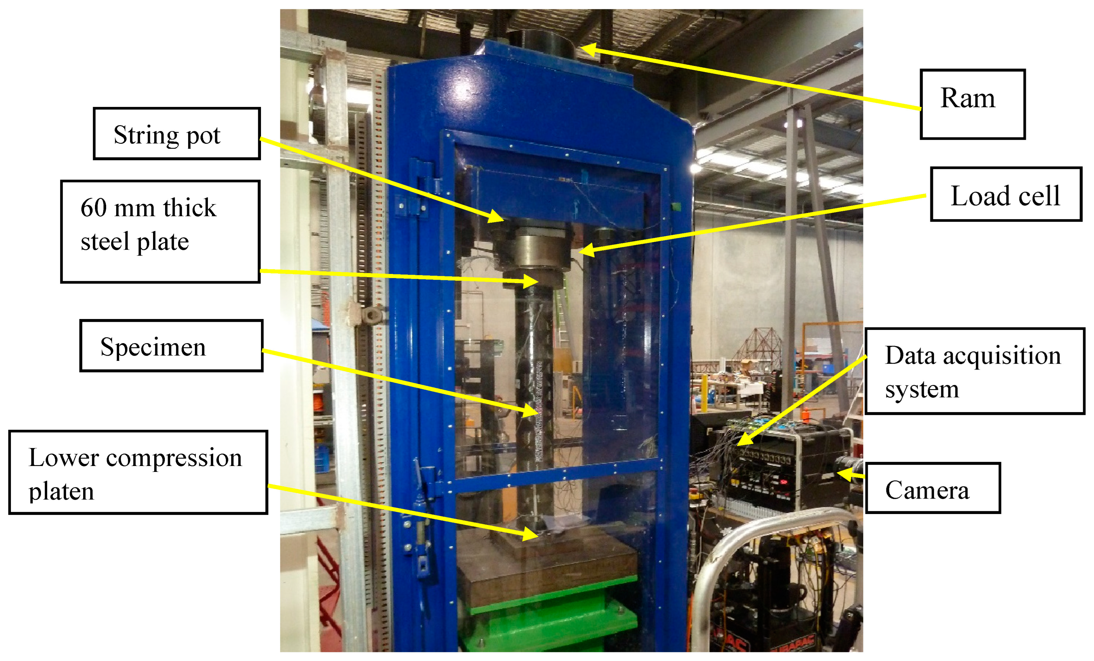
The label of each specimen consists of “CL”, denoting a CFRP-encased long column, followed by inner steel tube diameter and percentage of rubber replacement (0%, 15%, or 30%). For example, CL-I60-30 refers to the hybrid double-skin slender specimen with CFRP outer tube, inner steel tube of 60.3 mm diameter, and a rubber replacement ratio of 30. The heights of all three columns were 1000 mm. The coarse aggregates included 7–10 mm and 1–4 mm crushed rock; 10 mm aggregate was the maximum aggregate size. Rubber samples of 7–10 mm and 1–5 mm were obtained from scrap tyre and used to replace the coarse and fine aggregates, respectively. The grain size of the fine sand was 0.2–6 mm and Portland cement was used as the binding material. The compressive strength of the control concrete was considered 50.13 MPa and the strengths of 15% and 30% rubberised concrete found from testing were 25.84 MPa and 9.75 MPa, respectively. Figure 1 shows the experimental setup of the slender hybrid column. The specimen was placed on the lower compression platen and a 60 mm thick plate was used on top of the specimen to ensure uniform compression. A universal data acquisition system with a 500-tonne load cell was used with 1 mm/min displacement control regime. The detail of the experimental setup and procedure can be found in Khusru et al. [11].
2.2. Finite Element Modelling of Hybrid Slender RuDSTC
Using the experimental results of the authors on axially loaded hybrid slender RuDSTC, a finite element model was developed and validated. Three slender column specimens, namely, CL-I60-00, CL-I60-15, and CL-I60-30, were successfully modelled and validated using the ABAQUS software package.
2.2.1. Numerical Modelling Approach
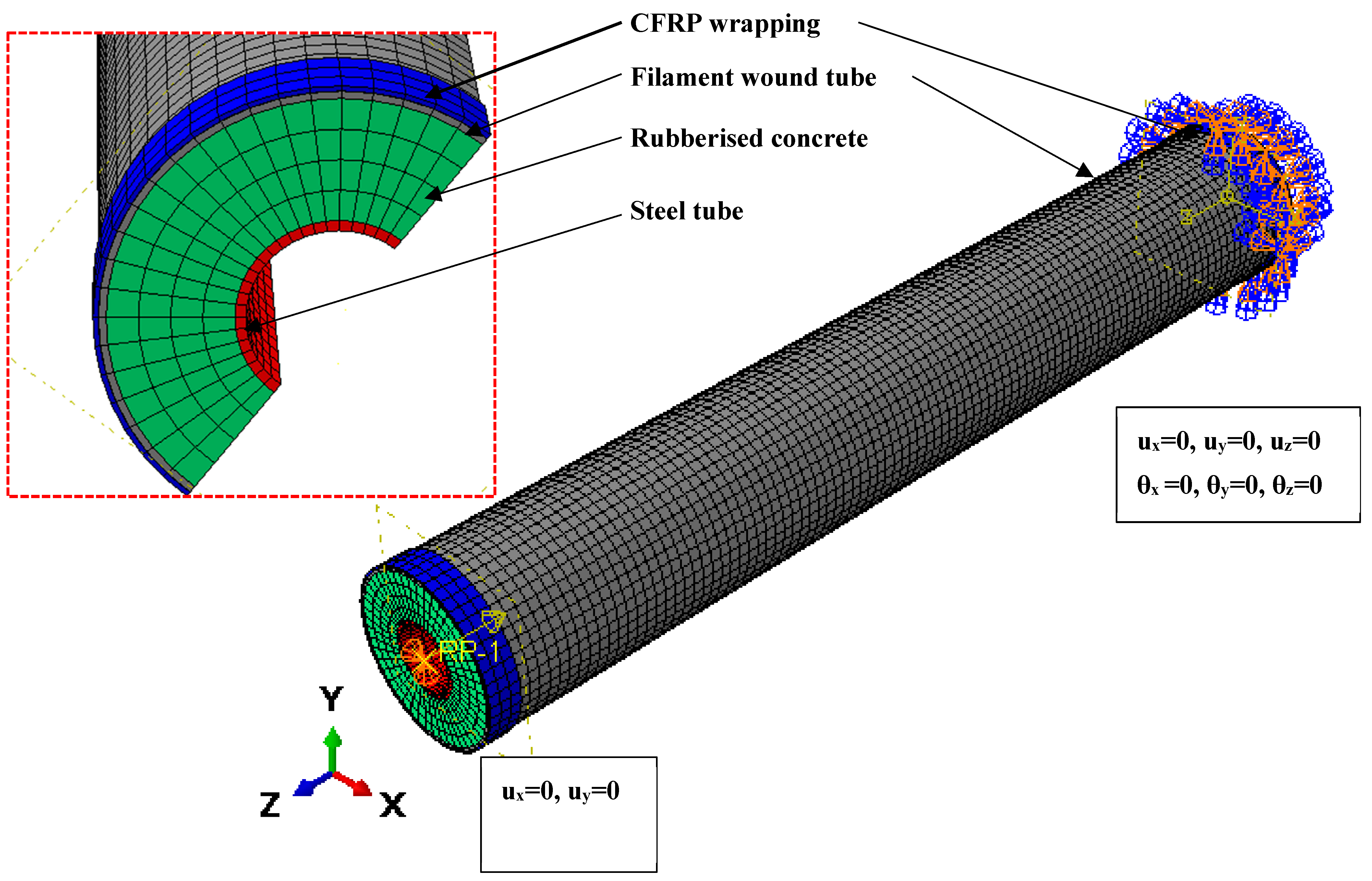
The three different components of the numerical model, namely, circular hollow steel (CHS) tube, composite laminates for filament wound CFRP, and rubberised concrete were developed as shown in Figure 2. The appropriate selection of the elements for the different parts is an important aspect of FE analysis, as the accuracy of the result depends on it. Based on the literature on previous FE analyses [25,26], S4R shell elements with hourglass control and reduced integration were used for steel, conventional shell elements S4R were used for the filament-wound CFRP tube, and eight-node linear solid elements C3D8R with reduced integration and hourglass control were chosen to model the rubberised concrete. Quadratic quadrilateral elements S8R were used to model the CFRP layer used in the experiment at the top and bottom ends of the column to prevent premature failure of the CFRP tube at the ends.
2.2.2. Material Models
The numerical model of hybrid RuDSTC involves three different materials bonded together to behave as a singular composite unit. To simulate CFRP filament-wound tube orthotropic material model, the composite layup option was used to provide the layup properties and orientation. The fibre orientation of the tube was 20%, 40%, and 40% fibres at angles of ±15, ±40, and ±75, respectively. Symmetry was considered while assigning the layout properties. Hashin damage criteria [27] was used similar to in Toh et al. [28] to simulate the damage behaviour. The material properties of the filament-wound tube used in this simulation are listed in Table 2.
In the ABAQUS software package, several concrete material models are available. the concrete damage plasticity model (CDPM) was selected, as it showed reasonably accurate predictions under uniform and nonuniform confinements of the FRP jacket [29,30], steel confined concrete [31], and various concrete types [32]. The inputs of concrete plasticity parameters such as the shape factor K was obtained from [25], and the ratio of biaxial to uniaxial compression stress was obtained from the empirical equation of Papanikolaou and Kappos [33]. Similar to the study of Ayough et al. [26] and Khusru et al. [8], the rubberised concrete model suggested by Bompa et al. [1,34] is used in this study. The stress–strain model of rubberised concrete was developed in three stages using inputs of the rubber replacement ratio ρvr, unconfined compressive strength fco, the elastic modulus, and aggregate size replaced with rubber particles γ in the equations.
For this concrete model, the inputs required are rubber replacement ratio, unconfined compressive strength of control concrete and rubberised concrete, and modulus of elasticity of concrete. Up to 30% of the unconfined strength of the concrete is considered elastic and the first stage of the stress–strain curve is considered linear up to this limit [35]. The corresponding elastic strain of the rubberised concrete is calculated using the elastic modulus. The final stage started with strain limit ε < εrc,el < εrc,1. The post-peak stage starts with a strain limit ε > εrc. The model can be summarized as follows:
Stage 1: for ε εrc,el
Stage 2: for εrc,el ε εrc,l
Stage 3: for ε εrcu
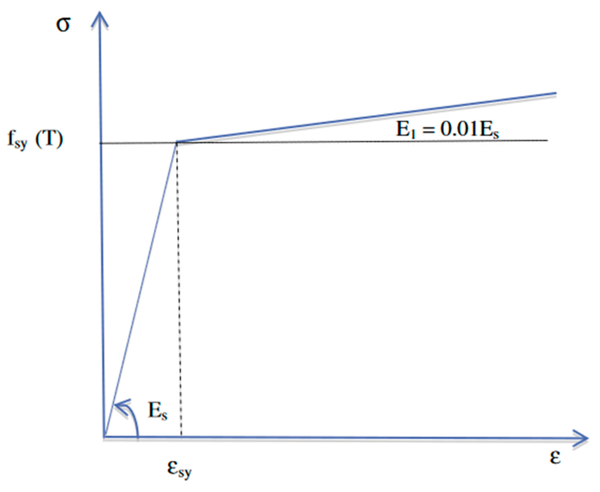
For steel tubes, the bilinear stress–strain model of steel as shown in Figure 3 suggested by Han et al. [36] was used as the material model as it was also used by Pagoulatou et al. [37] and Khusru et al. [11] for the simulation of double-skin columns.
This model consists of a linear elastic phase followed by a perfectly plastic phase. In ABAQUS, steel is considered plastic from yield point to final strain value of 3%. The modulus of elasticity of steel is considered as 200,000 MPa and Poisson’s ratio as 0.3.
The CFRP wrapped at the top and bottom was modelled as linear elastic brittle material in ABAQUS material model as a continuum shell element with no compression option to avoid complexity, similar to the study of Zeng et al. [30].
2.2.3. Surface Interaction, Boundary Conditions, and Load Application
To develop good bonding between the different parts, the mesh density of the component tubes of the composite column was kept uniform following the mesh size D/15 suggested by Tao et al. [38]. The top nodes were connected to the top reference point located at the centroid of the top surface and all degrees of freedom except those along the Z axes were restrained at the top. ENCASTRE boundary condition was applied at the bottom nodes to replicate the experimental condition. Commonly used two-step numerical technique of buckling analysis considering three buckling modes followed by the nonlinear analysis option Static RIKS method was used with the displacement control approach.
2.2.4. Validation of FE Model
Based on the numerical approach discussed in this paper, the axial load–axial displacement characteristics of the tested specimens and those obtained from the validated FE models CL-I60-00, CL-I60-15, and CL-I60-30, respectively, are presented in Figure 4. Bilinear shapes of load-displacement plots are observed in both the tests and FE results. It is evident that the two sets of load–displacement curves, peak axial loads, and maximum displacements compare very well. With the increase in rubber content from Figure 4a–c, the load displacement curve shows a flattened peak, indicating gradual failure of the columns.
Table 3 compares the peak axial load capacities (PEXP) and the maximum displacements (uEXP) obtained from the experiments of Khusru et al. [11] and the corresponding peak axial loads (PFE) and maximum displacements (uFE) obtained from the FE analyses.
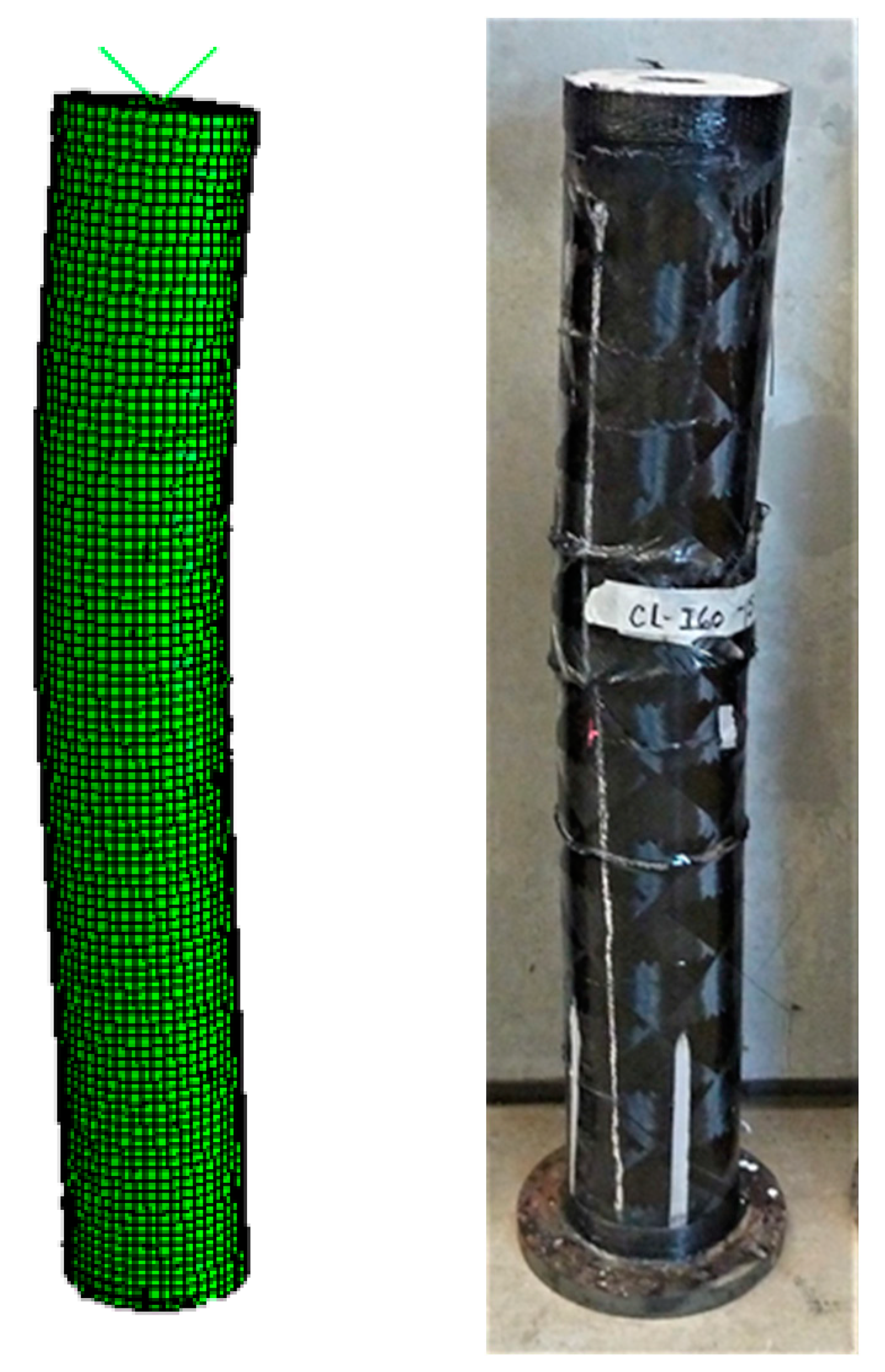
The comparison of failure shapes also showed similar kind of deformation of the hybrid RuDSTC. Figure 5 presents the global buckling shape of the experimental and FE specimen CL-I60-15 captured using FE simulation.
2.3. Validation of Eccentric Loading on Composite Column
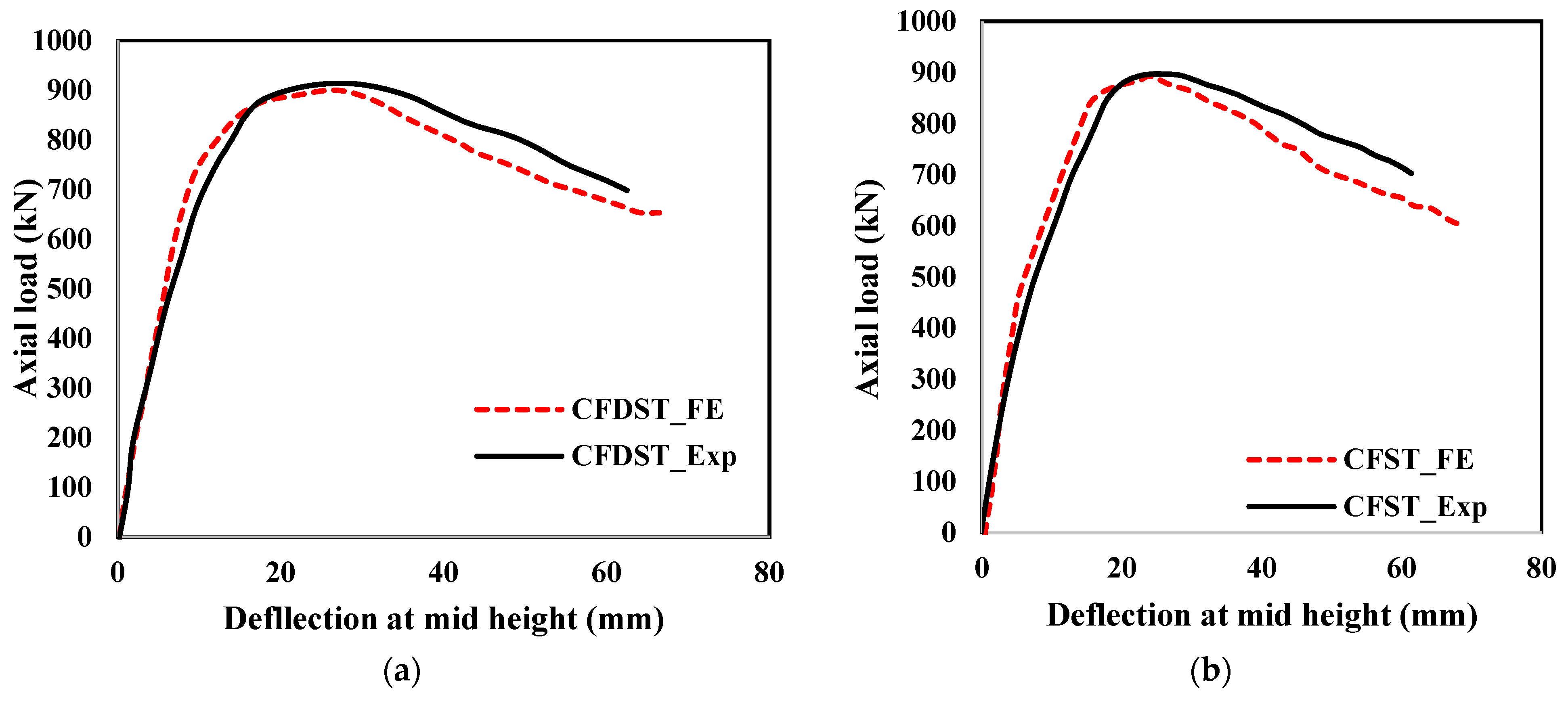
The experimental specimen of Alberto et al. [24] was developed in the ABAQUS standard environment. One single-skin circular CFST column and one double-skin circular column (termed as CFDST column in this paper), both having 3000 mm length were developed with 50 mm load centricity. The steel tube was modelled with S4R shell elements with reduced integration and hourglass control. To replicate the circular hollow section (CHS) behaviour of steel, a bilinear elastoplastic stress–strain model was used. Normal concrete of 30 MPa strength was modelled with eight-node linear brick elements C3D8R with hourglass control and reduced integration. The element size D/15 was considered as per Tao et al. [38]. Boundary conditions of both CFST and CFDST columns were assigned to match the end conditions of these columns in the experimental setup. Two bottom reference points were assigned, one at the 50 mm eccentricity at the left of the centroid of the top surface and the other at the same eccentricity at the bottom surface. These reference points were used to apply the boundary conditions of the top and the bottom ends. All the nodes of the top surface including the top nodes of steel and concrete tubes were constrained with the rigid body constraint option. The top nodes were allowed to move in the vertical direction only and rotation about X and Y axes were permitted. The bottom nodes were constrained in the same manner at the bottom reference point and no movement but rotations about all the axes were allowed. Surface-to-surface interaction defined by steel as master surface and concrete as slave surface was established. Hard contact was adopted as normal behaviour and penalty was considered as tangential behaviour.
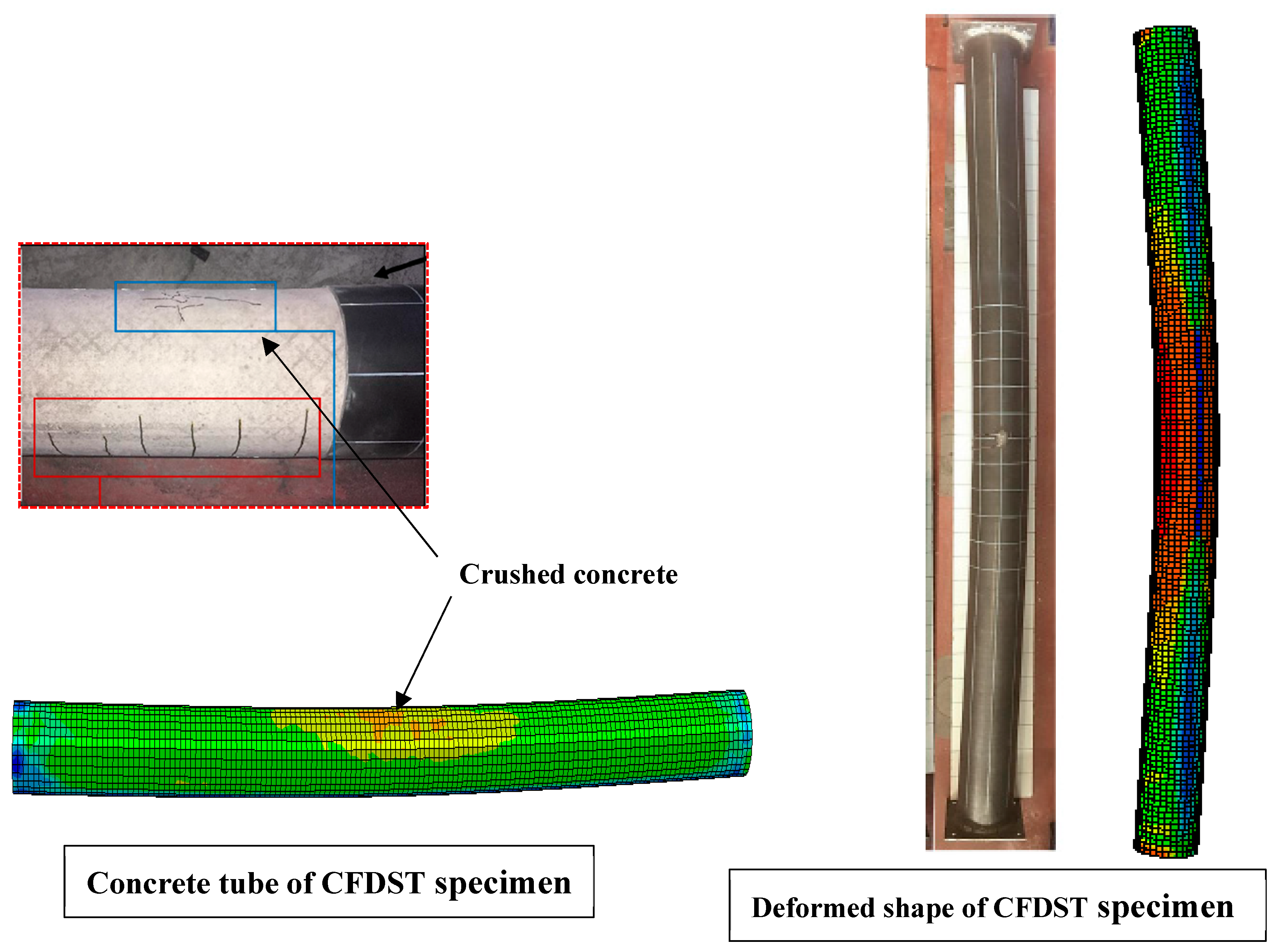
Buckling analysis using the linear perturbation command followed by the static RIKS was used as the analysis technique for modelling this eccentrically loaded column with the displacement control approach. Experimental and FE results of CFDST and CFST columns are presented in Figure 6a,b, respectively. Failure modes of the test and FE simulation are also compared in Figure 7. Good agreement was found, which ensures the reliability of the eccentric loading modelling technique.
3. Simulation of Eccentric Loading on Hybrid Columns and Parametric Study
Based on the validated numerical simulation technique of developing hybrid RuDSTCs and application of eccentric loading, the hybrid rubberised columns were analysed under both concentric and eccentric loadings to compare the changes in the column behaviour for different load eccentricities. The 200 mm outer CFRP tube of 2.5 mm thickness and 159 mm inner steel tube of 5 mm thickness with rubberised concrete infill was selected as the hybrid column for the parametric study. As per the recommendation of Zhang et al. [39], the hollow ratio was considered as 0.8 for the efficient use of the hybrid columns for serviceability. Different load eccentricities were applied by shifting the position of the reference points assigned at the top and bottom of the columns tied with the top and bottom set of nodes, respectively. The parameters considered for this study are percentages of rubber, load eccentricity, yield strength of interior steel tube, and concrete strength.
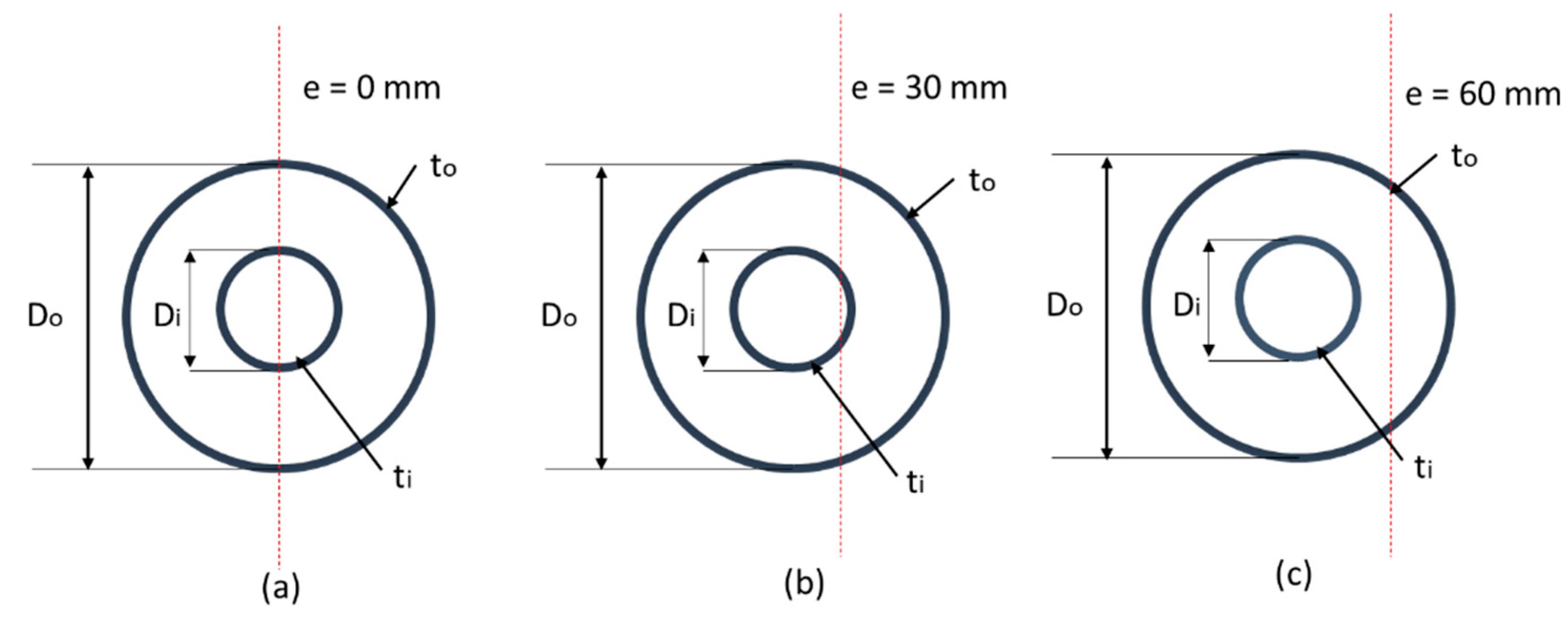
Figure 8 indicates the different eccentric load setups on the hybrid column. Here, Di indicates the inner diameter of the steel tube, Do is the outer diameter of the outer tube, and e indicates the eccentricity of the loading from the centre of the column.
The rubber replacement ratios considered were 0%, 15%, and 30%, and the corresponding stress–strain curve of the unconfined concrete was derived from Bompa et al. [1,34] using the proposed equations for the rubberised concrete. Eccentric loads at distances of approximately one-third (30 mm) and two-thirds (60 mm) of the outer radius from the centre of the column were applied. Commonly used hollow steel tube C250LO was chosen for most of the specimens and C450LO was also considered to ascertain the variation in behaviour for higher- and lower-yield strengths. Normal concrete with 40 MPa concrete strength is commonly used for the structural member in most infrastructure applications; in this study, one-parameter, high-strength concrete of 80 MPa was considered to analyse the impact of concrete brittleness in combination with the flexibility of rubber and eccentric arrangement. Table 4 shows the details of the specimens considered for the parametric study. Two types of specimen designations are used in this table. The first group of specimens, for example, have the designation fy = 250, 0%, 0. Here, the first value indicates the yield strength of steel, the second value indicates the percentage of rubber replacement, and the third value indicates the load eccentricity. The second group of specimens focusses on the concrete strength and is termed f′c = 40, 15%, 30. In this specimen designation, the first value indicates the unconfined strength of control concrete, the second value indicates the percentage of rubber replacement, and the third value represents the load eccentricity.
3.1. Axial Load–Axial Displacement Behaviour for Different Percentages of Rubber
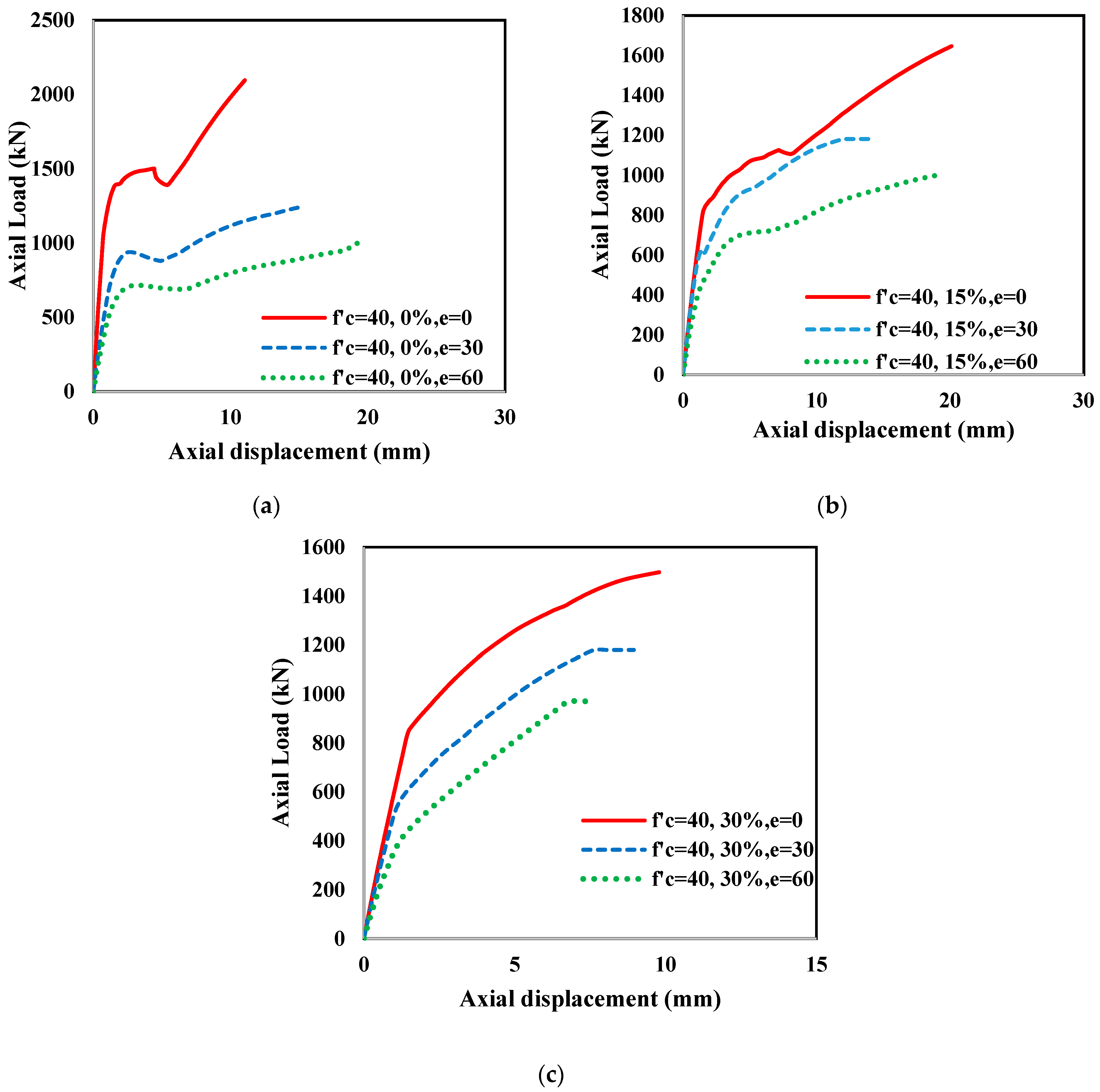
Axial load–axial displacement data from the FE analyses of the hybrid RuDSTC column are plotted in Figure 9 to ascertain the effect of load eccentricity with varying rubber content. The group of columns with unconfined concrete strength f′c = 40 MPa was selected to compare the effect of 0%, 15%, and 30% rubber for the load eccentricities of 0, 30, and 60 mm. Present results of FE analyses agree with previous test results regarding the reduction in axial capacity of the double-skin column [40] with increasing rubber content and eccentricity. For the non-rubberised column, a large load drop was observed, but with the increase in rubber content, the load drops were smaller and seemed to be somewhat mitigated. For 0% and 15% hybrid RuDSTC, a more pronounced increase in axial displacement was observed with the increase in load eccentricity, compared to that in the 30% hybrid counterpart.
Rubberised columns showed a smoother transition from the elastic first phase to the linear second part, indicating smooth dilation of the column compared to the non-rubberised columns. This tendency was more pronounced for the hybrid column with the greater rubber content of 30%. For concentric columns, the capacity decrease in the rubberised columns was significantly higher compared to the normal concrete-infilled hybrid column. For 30 mm eccentricity, the capacities of both the rubberised and non-rubberised columns were close. However, for 60 mm eccentricity, the column seemed to have a uniform transition between the first and second phase for both rubberised and non-rubberised columns, but the rubberised column showed smaller axial shortening for 60 mm eccentricity compared to 30 mm eccentricity.
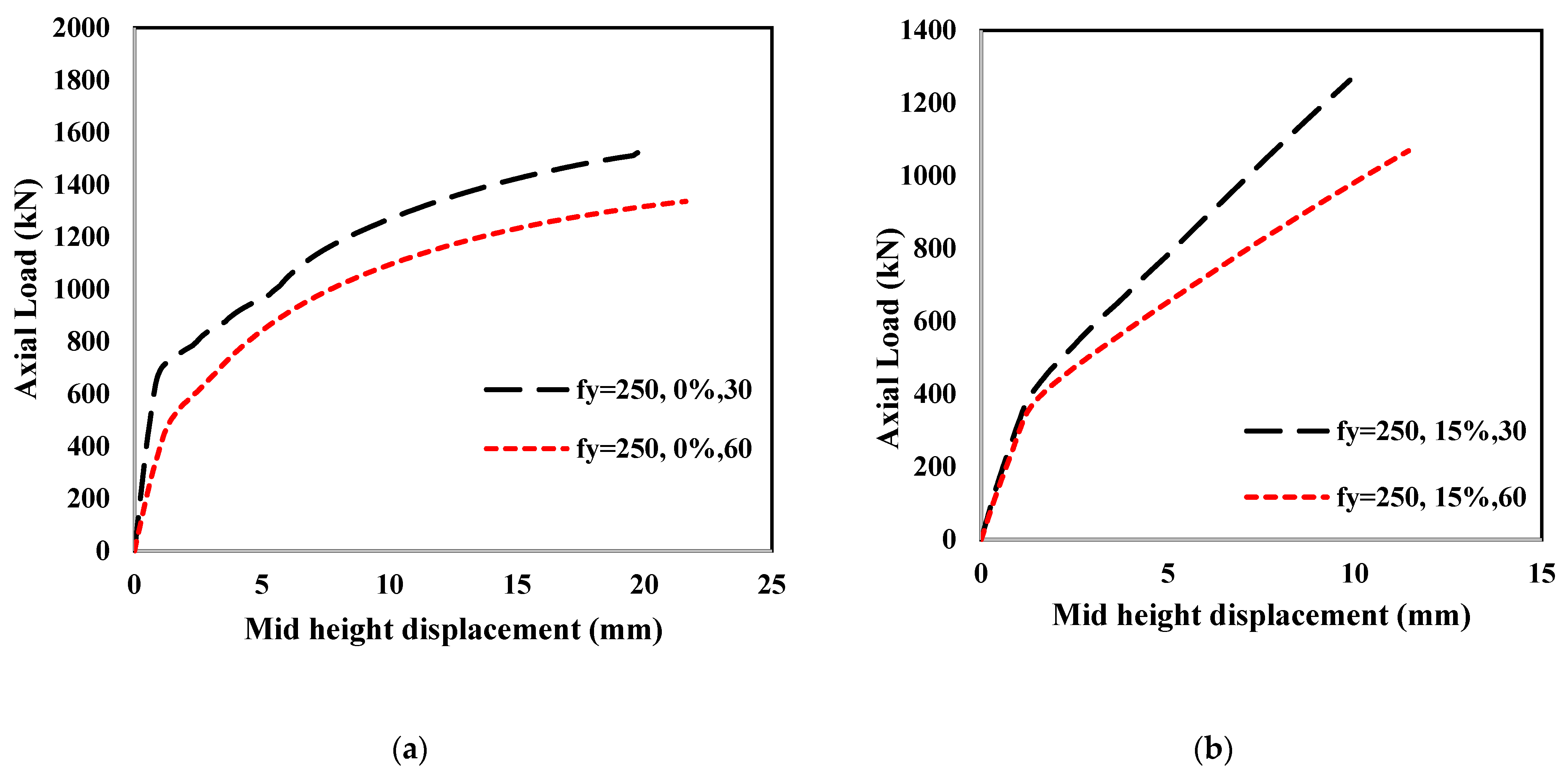
Figure 10 represents the axial load–mid-height lateral displacement curve of the hybrid columns. Mid-height displacement in the lateral direction of the circular column was obtained by taking a node on the outer surface of the column on the same side of the eccentric loading application. The hybrid columns showed a reduction in axial capacity due to increased bending moment. For 0% rubber content in Figure 10a, the capacities of fy = 250, 0%, 30 column with 30 mm eccentricity and fy = 250, 0%, 60 column with 60 mm eccentricity are 1552 kN and 1336 kN, respectively. The increase in 30 mm load eccentricity decreased the axial capacity by 13.92%.
3.2. Concrete Contribution Ratio (CCR) for Different Concrete Strength
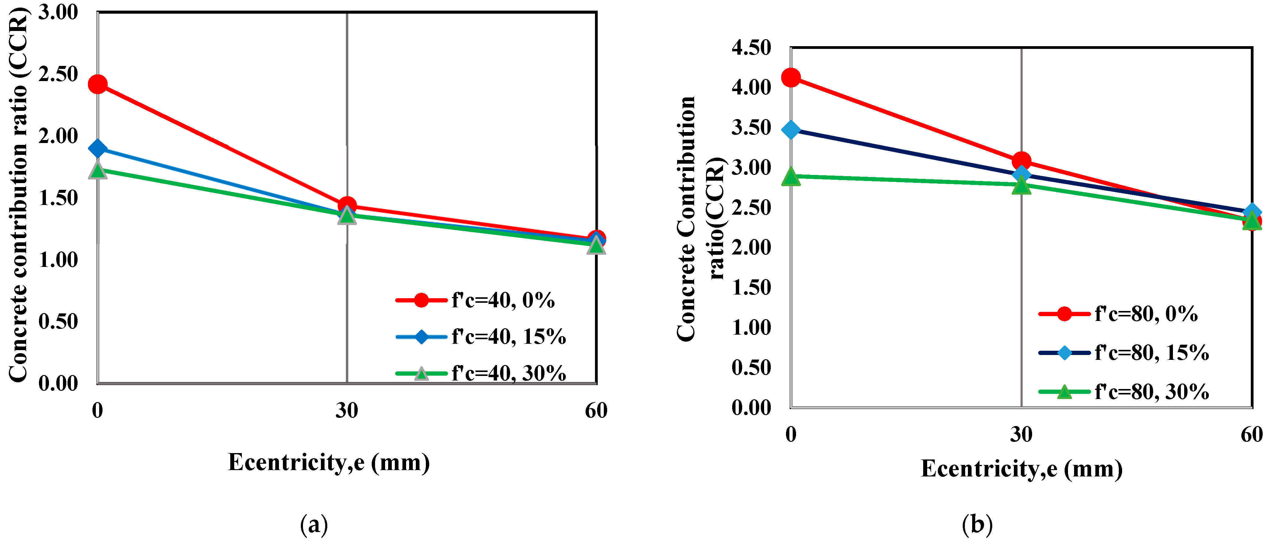
The concrete contribution ratio (CCR) is an important parameter used by researchers on double-skin columns [40,41]. CCR is the ratio of the total capacity of the hybrid column to the sum of the capacity of the CFRP tube and steel tube. The load capacity of the individual tube obtained from the experimental analysis of the authors [11] was used to calculate the concrete contribution of the hybrid column. Columns with control concrete strength 40 MPa and 80 MPa were selected to compare the CCRs, and the results are presented in Figure 11.
Figure 11 depicts that the contribution of concrete infill is higher in the concentric column with e = 0 mm and the value of CCR decreases significantly with increasing rubber content. However, increasing eccentricity to e = 30 mm in Figure 11a and e = 60 mm in Figure 11b, the CCR ratio decreases as a larger part of the concrete area is subjected to tensile stresses. The effect of rubber percentages becomes less significant, which is indicated by very close values of CCR.
This observation is also evident for high-strength concrete of 80 MPa control concrete strength. The maximum value of CCR was observed for concentric loading conditions. However as per Figure 11, rubberised concrete has a contribution similar to control concrete under larger eccentricities.
3.3. Strength Index (SI) for Different Yield Strengths of Steel
Strength index (SI) is another important parameter to ascertain the behaviour of the column. SI is calculated using the total capacity of the hybrid column from FE in comparison to the theoretical capacity of the column considering the three components (rubberised concrete, steel, and CFRP) of the hybrid column. Theoretical capacity can be calculated by combining the individual capacities of steel, rubberised concrete, and CFRP tube by the following equation:
Theoretical capacity of the hybrid column = ASfy + Aconfc + AFRPfFRP
Here, As, Acon, and AFRP represent the cross-sectional area of steel tube, concrete infill, and FRP tube, respectively, and fy, fc, and fFRP indicate the yield strength of steel, strength of concrete, and axial compressive strength of the CFRP tube, respectively. The corresponding values of the parameters of Equation (7) were obtained from the experimental investigation of the authors [11,12]. fy = 250 MPa and fy = 450 MPa column groups with load eccentricities 0, 30 mm, and 60 mm were chosen to compare their behaviours.
Figure 12 compares the nine specimens of the fy = 250 group with different rubber content and eccentricity. The FE values agree well with the theoretical predictions, as the SI value is close to unity for most of the specimens. It is evident from the figure that for the concentric load (e = 0), the strength index varies considerably for varying rubber content indicating lower strength index values for increasing rubber content, whereas for the higher eccentricity, the difference in SI value ceases.
For the fy = 450 group of columns, the SI values are less variable for e = 0 compared to fy = 250 columns, indicating that the higher strength of the inner tube does not have much effect on SI values for increasing rubber content. For higher eccentricities, SI values of rubberised concrete are close to those of normal concrete-infilled columns.
3.4. Comparison of the Axial Capacities of the Columns
Table 5 compares the axial capacities of the thirty-six hybrid RuDSTCs developed and analysed in this study. The last column in the table indicates the capacity reductions in the hybrid column due to different eccentricities and percentages of rubber. Calculations were made on a group basis and the columns without rubber and zero eccentricity were considered as the control columns to calculate the capacity reductions in that group. Analysing the results in Table 5, it can be summarised that the columns with normal concrete infill (0% rubber) underwent 25% and 41% capacity reductions on average at load eccentricities of 30 mm and 60 mm, respectively. Average capacity reductions for 15% hybrid RuDSTC were 35% and 40%, respectively, and those for 30% hybrid RuDSTC were 38% and 44%, respectively. It can be said that the rubberised column showed similar capacity reduction to the normal concrete column for higher eccentricities.
4. Conclusions
Rubberised concrete has emerged as a sustainable solution, providing better ductility when used as an infill material with single- or double-skin confined columns. In order to use this in column under realistic conditions, determination of its behaviour under eccentric loads is necessary. This paper developed and applied a finite element modelling technique for the hybrid column with filament-wound exterior tube, rubberised concrete infill, and steel interior tube yield under eccentric compression loading. The finite element model was validated with the results from experiments and used to carry out an extensive parametric study. The parameters considered in this study were load eccentricity, percentage of rubber, concrete strength, and steel tube strength. Based on the results of the present study, the key findings can be summarised as follows:
- These hybrid columns have merit in realistic applications, especially when ductility is desirable.
- Double-skin confinement effectively restored the strength of the hybrid column. Though the rubber replacement ratio had some effect on the axial capacity of the columns, at higher eccentricity, this effect was negligible.
- Axial load–axial displacement behaviour of the hybrid columns showed a smoother transition from the elastic first phase to the linear second phase, indicating smooth dilation of the column compared to the non-rubberised columns. This tendency was more pronounced for the hybrid column with the greater rubber content of 30%.
- The behaviour of the column with increasing rubber percentage and load eccentricity is acceptable and enables the hybrid RuDSTC to be effectively used in locations witht greater load eccentricities.
- Further exploration for future study could involve testing the eccentrically loaded hybrid RuDSTC column under impact, cyclic, or combined loading, and experimenting with diverse combinations of material parameters.
Author Contributions
Conceptualization, S.K., S.F., D.P.T. and M.E.; Methodology, S.K., S.F., D.P.T. and M.E.; Validation, S.K.; Formal analysis, S.K.; Investigation, S.K.; Resources, S.F. and D.P.T.; Data curation, S.K.; Writing—original draft, S.K.; Writing—review & editing, S.K., D.P.T., M.E. and S.F.; Supervision, D.P.T., M.E. and S.F.; Project administration, S.F.; Funding acquisition, S.F. All authors have read and agreed to the published version of the manuscript.
Funding
This research received no external funding.
Data Availability Statement
The data presented in this study are available on request from the corresponding author. The data are not publicly available due to the data also form part of an ongoing study.
Acknowledgments
The authors would like to thank Queensland University of Technology (QUT) for providing support (the high-performance computing (HPC) facility’s software for analysis) in carrying out the work reported in this paper. The authors also wish to thank the technical staff and IT staff at the Faculty of Engineering at QUT for their assistance in carrying out this research.
Conflicts of Interest
The authors declare no conflict of interest.
References
- Bompa, D.V.; Elghazouli, A.Y. Stress–strain response and practical design expressions for FRP-confined recycled tyre rubber concrete. Constr. Build. Mater. 2020, 237, 117633. [Google Scholar] [CrossRef]
- Zhou, T. New physical science behind climate change: What does IPCC AR6 tell us? Innovation 2021, 2, 100173. [Google Scholar] [CrossRef] [PubMed]
- Garito, M.A.; Caforio, A.; Falegnami, A.; Tomassi, A.; Romano, E. Shape the EU future citizen. Environmental education on the European Green Deal. Energy Rep. 2023, 9, 340–354. [Google Scholar] [CrossRef]
- Záleská, M.; Pavlík, Z.; Čítek, D.; Jankovský, O.; Pavlíková, M. Eco-friendly concrete with scrap-tyre-rubber-based aggregate—Properties and thermal stability. Constr. Build. Mater. 2019, 225, 709–722. [Google Scholar] [CrossRef]
- Khaloo, A.R.; Dehestani, M.; Rahmatabadi, P. Mechanical properties of concrete containing a high volume of tire–rubber particles. Waste Manag. 2008, 28, 2472–2482. [Google Scholar] [CrossRef] [PubMed]
- Khusru, S.; Fawzia, S.; Thambiratnam, D.P.; Elchalakani, M. Confined rubberised concrete tubular column for high-performance structures–Review. Constr. Build. Mater. 2021, 276, 122216. [Google Scholar] [CrossRef]
- Huang, Z.; Zheng, K.; Wei, Y.; Liu, L.; Tang, X.; Qin, X. Compressive performance of SWSSC-filled CFRP-stainless steel composite tube columns. Constr. Build. Mater. 2023, 385, 131471. [Google Scholar] [CrossRef]
- Deng, Y.; Liang, J.-F.; Li, W. Axial Performance of Steel Fiber-Reinforced Rubberized Concrete-Filled Circular Tubular Columns. Adv. Mater. Sci. Eng. 2021, 2021, 6678802. [Google Scholar] [CrossRef]
- Youssf, O.; Hassanli, R.; Mills, J.E.; Zhuge, Y. Axial compression behaviour of hybrid double-skin tubular columns filled with rubcrete. J. Compos. Sci. 2019, 3, 62. [Google Scholar] [CrossRef]
- Youssf, O.; Hassanli, R.; Mills, J.E. Mechanical performance of FRP-confined and unconfined crumb rubber concrete containing high rubber content. J. Build. Eng. 2017, 11, 115–126. [Google Scholar] [CrossRef]
- Khusru, S.; Fawzia, S.; Thambiratnam, D.P.; Elchalakani, M. Experimental testing of Novel Hybrid Rubberised Concrete Double Skin Tubular Columns with filament Wound CFRP tube under axial compressive loading. Compos. Struct. 2021, 276, 114568. [Google Scholar] [CrossRef]
- Khusru, S.; Thambiratnam, D.P.; Elchalakani, M.; Fawzia, S. Hybrid double skin FRP–Steel column with rubberised concrete infill under axial loading. Eng. Struct. 2021, 249, 113267. [Google Scholar] [CrossRef]
- Lee, S.-H.; Uy, B.; Kim, S.-H.; Choi, Y.-H.; Choi, S.-M. Behavior of high-strength circular concrete-filled steel tubular (CFST) column under eccentric loading. J. Constr. Steel Res. 2011, 67, 1–13. [Google Scholar] [CrossRef]
- Liang, Q.Q.; Fragomeni, S. Nonlinear analysis of circular concrete-filled steel tubular short columns under eccentric loading. J. Constr. Steel Res. 2010, 66, 159–169. [Google Scholar] [CrossRef]
- Liu, D. Behaviour of eccentrically loaded high-strength rectangular concrete-filled steel tubular columns. J. Constr. Steel Res. 2006, 62, 839–846. [Google Scholar] [CrossRef]
- Ahmed, M.; Liang, Q.Q.; Patel, V.I.; Hadi, M.N. Experimental and numerical studies of square concrete-filled double steel tubular short columns under eccentric loading. Eng. Struct. 2019, 197, 109419. [Google Scholar] [CrossRef]
- Li, W.; Han, L.-H.; Ren, Q.-X.; Zhao, X.-L. Behavior and calculation of tapered CFDST columns under eccentric compression. J. Constr. Steel Res. 2013, 83, 127–136. [Google Scholar] [CrossRef]
- Pour, A.F.; Gholampour, A.; Zheng, J.; Ozbakkaloglu, T. Behavior of FRP-confined high-strength concrete under eccentric compression: Tests on concrete-filled FRP tube columns. Compos. Struct. 2019, 220, 261–272. [Google Scholar] [CrossRef]
- Alelaimat, R.A.; Sheikh, M.N.; Hadi, M.N. Behaviour of square concrete filled FRP tube columns under concentric, uniaxial eccentric, biaxial eccentric and four-point bending loads. Thin-Walled Struct. 2021, 168, 108252. [Google Scholar] [CrossRef]
- Yu, T.; Wong, Y.; Teng, J. Behavior of hybrid FRP-concrete-steel double-skin tubular columns subjected to eccentric compression. Adv. Struct. Eng. 2010, 13, 961–974. [Google Scholar] [CrossRef]
- Xie, P. Behavior of Large-Scale Hybrid FRP-Concrete-Steel Double-Skin Tubular Columns Subjected to Concentric and Eccentric Compression. Ph.D. Thesis, Hong Kong Polytechnic University, Hong Kong, China, 2018. [Google Scholar]
- Khusru, S.; Fawzia, S.; Thambiratnam, D.P.; Elchalakani, M. Behaviour of Filament Wound FRP-Rubberised Concrete-Steel Hybrid Double Skin Tubular Column (Hybrid RuDSTC) Under Axial Loading; Springer International Publishing: Cham, Switzerland, 2022; pp. 1076–1084. [Google Scholar]
- ABAQUS 6.14. ABAQUS/CAE User’s Guide; Dassault Systèmes Simulia Corp.: Providence, RI, USA, 2014; Volume 6. [Google Scholar]
- Albero, V.; Ibañez, C.; Piquer, A.; Hernández-Figueirido, D. Behaviour of slender concrete-filled dual steel tubular columns subjected to eccentric loads. J. Constr. Steel Res. 2021, 176, 106365. [Google Scholar] [CrossRef]
- Hany, N.F.; Hantouche, E.G.; Harajli, M.H. Finite element modeling of FRP-confined concrete using modified concrete damaged plasticity. Eng. Struct. 2016, 125, 1–14. [Google Scholar] [CrossRef]
- Ayough, P.; Ibrahim, Z.; Sulong, N.H.R.; Hsiao, P.-C.; Elchalakani, M. Numerical analysis of square concrete-filled double skin steel tubular columns with rubberized concrete. Structures 2021, 32, 1026–1047. [Google Scholar] [CrossRef]
- Hashin, Z.; Rotem, A. A fatigue failure criterion for fiber reinforced materials. J. Compos. Mater. 1973, 7, 448–464. [Google Scholar] [CrossRef]
- Toh, W.; Tan, L.B.; Tse, K.M.; Giam, A.; Raju, K.; Lee, H.P.; Tan, V.B.C. Material characterization of filament-wound composite pipes. Compos. Struct. 2018, 206, 474–483. [Google Scholar] [CrossRef]
- Yu, T.; Teng, J.G.; Wong, Y.L.; Dong, S.L. Finite element modeling of confined concrete-II: Plastic-damage model. Eng. Struct. 2010, 32, 680–691. [Google Scholar] [CrossRef]
- Zeng, J.; Guo, Y.; Li, L.; Chen, W. Behavior and Three-Dimensional Finite Element Modeling of Circular Concrete Columns Partially Wrapped with FRP Strips. Polymers 2018, 10, 253. [Google Scholar] [CrossRef]
- Duarte, A.P.C.; Silva, B.A.; Silvestre, N.; de Brito, J.; Júlio, E.; Castro, J.M. Finite element modelling of short steel tubes filled with rubberized concrete. Compos. Struct. 2016, 150, 28–40. [Google Scholar] [CrossRef]
- Nasrin, S.; Ibrahim, A. Numerical study on the low-velocity impact response of ultra-high-performance fiber reinforced concrete beams. Structures 2019, 20, 570–580. [Google Scholar] [CrossRef]
- Papanikolaou, V.K.; Kappos, A.J. Confinement-sensitive plasticity constitutive model for concrete in triaxial compression. Int. J. Solids Struct. 2007, 44, 7021–7048. [Google Scholar] [CrossRef]
- Bompa, D.V.; Elghazouli, A.Y. Behaviour of confined rubberised concrete members under combined loading conditions. Mag. Concr. Res. 2019, 73, 555–573. [Google Scholar] [CrossRef]
- Bompa, D.; Elghazouli, A.; Xu, B.; Stafford, P.; Ruiz-Teran, A. Experimental assessment and constitutive modelling of rubberised concrete materials. Constr. Build. Mater. 2017, 137, 246–260. [Google Scholar] [CrossRef]
- Han, L.-H.; Li, Y.-J.; Liao, F.-Y. Concrete-filled double skin steel tubular (CFDST) columns subjected to long-term sustained loading. Thin-Walled Struct. 2011, 49, 1534–1543. [Google Scholar] [CrossRef]
- Pagoulatou, M.; Sheehan, T.; Dai, X.; Lam, D. Finite element analysis on the capacity of circular concrete-filled double-skin steel tubular (CFDST) stub columns. Eng. Struct. 2014, 72, 102–112. [Google Scholar] [CrossRef]
- Tao, Z.; Han, L.-H.; Zhao, X.-L. Behaviour of concrete-filled double skin (CHS inner and CHS outer) steel tubular stub columns and beam-columns. J. Constr. Steel Res. 2004, 60, 1129–1158. [Google Scholar] [CrossRef]
- Zhang, B.; Teng, J.G.; Yu, T. Compressive Behavior of Double-Skin Tubular Columns with High-Strength Concrete and a Filament-Wound FRP Tube. J. Compos. Constr. 2017, 21, 04017029. [Google Scholar] [CrossRef]
- Elchalakani, M.; Dong, M.; Karrech, A. Interaction diagram of rubberised concrete filled circular hollow sections. J. Civ. Eng. Constr. 2019, 8, 1–7. [Google Scholar] [CrossRef]
- Ibañez, C.; Piquer, A.; Hernández-Figueirido, D.; Martínez-Ramos, Ó. 08.37: Experimental analysis of concrete-filled double skin tubular columns subjected to eccentric loads. ce/papers 2017, 1, 2138–2146. [Google Scholar] [CrossRef]
Figure 1.
Experimental setup of slender hybrid RuDSTC under axial loading.

Figure 2.
Details of hybrid RuDSTC model with fixed boundary conditions at the bottom and free at the top.
Figure 2.
Details of hybrid RuDSTC model with fixed boundary conditions at the bottom and free at the top.

Figure 3.
Bilinear stress–strain curve of steel [37].
Figure 3.
Bilinear stress–strain curve of steel [37].

Figure 4.
The experimental [11] and FE results of hybrid RuDSTCs (a) CL-I60-00, (b) CL-I60-15, and (c) CL-I60-30.
Figure 4.
The experimental [11] and FE results of hybrid RuDSTCs (a) CL-I60-00, (b) CL-I60-15, and (c) CL-I60-30.

Figure 5.
Comparison of failure shapes between experiment [11] and FE analysis of the CL-60-15 specimen.
Figure 5.
Comparison of failure shapes between experiment [11] and FE analysis of the CL-60-15 specimen.

Figure 6.
The experimental and FE results of (a) CFDST and (b) CFST columns.

Figure 7.
Failure modes of specimens of Albero et al. [24].
Figure 7.
Failure modes of specimens of Albero et al. [24].

Figure 8.
Eccentric loading conditions on hybrid RuDSTC column (a) e = 0 mm, (b) e = 30 mm and (c) e = 60 mm.
Figure 8.
Eccentric loading conditions on hybrid RuDSTC column (a) e = 0 mm, (b) e = 30 mm and (c) e = 60 mm.

Figure 9.
Axial load–axial displacement behaviour of the hybrid column under different eccentricity and rubber percentages: (a) 0% rubber, (b) 15% rubber, and (c) 30% rubber.
Figure 9.
Axial load–axial displacement behaviour of the hybrid column under different eccentricity and rubber percentages: (a) 0% rubber, (b) 15% rubber, and (c) 30% rubber.

Figure 10.
Axial load–mid-height displacement behaviour of the hybrid column under different eccentricities: (a) e = 30 mm and (b) e = 60 mm.
Figure 10.
Axial load–mid-height displacement behaviour of the hybrid column under different eccentricities: (a) e = 30 mm and (b) e = 60 mm.

Figure 11.
Variation in concrete contribution ratio (CCR) with load eccentricity. (a) Concrete strength 40 MPa. (b) Concrete strength 80 MPa.
Figure 11.
Variation in concrete contribution ratio (CCR) with load eccentricity. (a) Concrete strength 40 MPa. (b) Concrete strength 80 MPa.

Figure 12.
Comparison of strength index of rubberised concrete with load eccentricity: (a) fy = 250 group of specimens and (b) fy = 450 group of specimens.
Figure 12.
Comparison of strength index of rubberised concrete with load eccentricity: (a) fy = 250 group of specimens and (b) fy = 450 group of specimens.


Table 1.
Specimen details.
| Sl No. | Specimen ID | Outer FRP Tube Properties | Inner Steel Tube Properties | Rubber Replacement | ||
|---|---|---|---|---|---|---|
| Do (mm) | to (mm) | Di (mm) | ti (mm) | |||
| 1. | CL-I60-00 | 152 | 2.5 | 60.3 | 3.6 | 0% |
| 2. | CL-I60-15 | 152 | 2.5 | 60.3 | 3.6 | 15% |
| 3. | CL-I60-30 | 152 | 2.5 | 60.3 | 3.6 | 30% |
Table 2.
Properties of filament-wound CFRP tube.
| Parameter | Value |
|---|---|
| Modulus of elasticity (longitudinal) | 65 GPa |
| Compressive strength (longitudinal) | 140 MPa |
| Tensile strength (longitudinal) | 592 MPa |
| Compressive strength (transverse) | 140 MPa |
| Tensile strength (transverse) | 242 MPa |
Table 3.
Comparison of experimental and FE results.
| Specimen | PExp (kN) | PFE (kN) | uExp (mm) | uFE (mm) | PExp/PFE | uExp/uEE |
|---|---|---|---|---|---|---|
| CL-I60-00 | 1432 | 1405 | 22.39 | 23.29 | 1.02 | 0.96 |
| CL-I60-15 | 1164 | 1202 | 26.69 | 28.21 | 0.97 | 0.95 |
| CL-I60-30 | 781 | 716 | 23.06 | 20.25 | 0.92 | 1.13 |
| Mean | 0.97 | 1.01 | ||||
| COV | 0.05 | 0.10 |
The mean ratios of experimental to FE loads and experimental to FE displacements are 0.97 and 1.01, respectively, while the corresponding coefficients of variance (COV) are 0.05 and 0.10, respectively, which indicate a good agreement between the experimental and FE results.
Table 4.
Detail dimensions and properties of hybrid RuDSTCs used for parametric study.
| Specimen ID | % Rubber | FRP Tube | Steel Tube | Control Concrete Strength | |||
|---|---|---|---|---|---|---|---|
| Do (mm) | to (mm) | Di (mm) | ti (mm) | fy (mm) | f′c (MPa) | ||
| fy = 250, 0%, 0 | 0% | 200 | 2.5 | 159 | 5 | 250 | 50 |
| fy = 250, 0%, 30 | 0% | 200 | 2.5 | 159 | 5 | 250 | |
| fy = 250, 0%, 60 | 0% | 200 | 2.5 | 159 | 5 | 250 | |
| fy = 250, 15%, 0 | 15% | 200 | 2.5 | 159 | 5 | 250 | |
| fy = 250, 15%, 30 | 15% | 200 | 2.5 | 159 | 5 | 250 | |
| fy = 250, 15%, 60 | 15% | 200 | 2.5 | 159 | 5 | 250 | |
| fy = 250, 30%, 0 | 30% | 200 | 2.5 | 159 | 5 | 250 | |
| fy = 250, 30%, 30 | 30% | 200 | 2.5 | 159 | 5 | 250 | |
| fy = 250, 30%, 60 | 30% | 200 | 2.5 | 159 | 5 | 250 | |
| fy = 450, 0%, 0 | 0% | 200 | 2.5 | 159 | 5 | 450 | |
| fy = 450, 0%, 30 | 0% | 200 | 2.5 | 159 | 5 | 450 | 50 |
| fy = 450, 0%, 60 | 0% | 200 | 2.5 | 159 | 5 | 450 | |
| fy = 450, 15%, 0 | 15% | 200 | 2.5 | 159 | 5 | 450 | |
| fy = 450, 15%, 30 | 15% | 200 | 2.5 | 159 | 5 | 450 | |
| fy = 450, 15%, 60 | 15% | 200 | 2.5 | 159 | 5 | 450 | |
| fy = 450, 30%, 0 | 30% | 200 | 2.5 | 159 | 5 | 450 | |
| fy = 450, 30%, 30 | 30% | 200 | 2.5 | 159 | 5 | 450 | |
| fy = 450, 30%, 60 | 30% | 200 | 2.5 | 159 | 5 | 450 | |
| f′c = 40, 0%, 0 | 0% | 200 | 2.5 | 159 | 5 | 250 | 40 |
| f′c = 40, 0%, 30 | 15% | 200 | 2.5 | 159 | 5 | 250 | |
| f′c = 40, 0%, 60 | 30% | 200 | 2.5 | 159 | 5 | 250 | |
| f′c = 40, 15%, 0 | 0% | 200 | 2.5 | 159 | 5 | 250 | |
| f′c = 40, 15%, 30 | 15% | 200 | 2.5 | 159 | 5 | 250 | |
| f′c = 40, 15%, 60 | 30% | 200 | 2.5 | 159 | 5 | 250 | |
| f′c = 40, 30%, 0 | 0% | 200 | 2.5 | 159 | 5 | 250 | |
| f′c = 40, 30%, 30 | 15% | 200 | 2.5 | 159 | 5 | 250 | |
| f′c = 40, 30%, 60 | 30% | 200 | 2.5 | 159 | 5 | 250 | |
| f′c = 80, 0%, 0 | 0% | 200 | 2.5 | 159 | 5 | 250 | 80 |
| f′c = 80, 0%, 30 | 15% | 200 | 2.5 | 159 | 5 | 250 | |
| f′c = 80, 0%, 60 | 30% | 200 | 2.5 | 159 | 5 | 250 | |
| f′c = 80, 15%, 0 | 0% | 200 | 2.5 | 159 | 5 | 250 | |
| f′c = 80, 15%, 30 | 15% | 200 | 2.5 | 159 | 5 | 250 | |
| f′c = 80, 15%, 60 | 30% | 200 | 2.5 | 159 | 5 | 250 | |
| f′c = 80, 30%, 0 | 0% | 200 | 2.5 | 159 | 5 | 250 | |
| f′c = 80, 30%, 30 | 15% | 200 | 2.5 | 159 | 5 | 250 | |
| f′c = 80, 30%, 60 | 30% | 200 | 2.5 | 159 | 5 | 250 | |
Table 5.
Comparison of the axial capacity of the hybrid column.
| Specimen ID | % Rubber | Eccentricity (mm) | Axial Capacity (kN) | % Capacity Reduction |
|---|---|---|---|---|
| fy = 250, 0%, 0 | 0% | 0 | 1980 | - |
| fy = 250, 0%, 30 | 0% | 30 | 1552 | 22 |
| fy = 250, 0%, 60 | 0% | 60 | 1336 | 33 |
| fy = 250, 15%, 0 | 15% | 0 | 1363 | 31 |
| fy = 250, 15%, 30 | 15% | 30 | 1228 | 38 |
| fy = 250, 15%, 60 | 15% | 60 | 1068 | 46 |
| fy = 250, 30%, 0 | 30% | 0 | 1195 | 40 |
| fy = 250, 30%, 30 | 30% | 30 | 1165 | 41 |
| fy = 250, 30%, 60 | 30% | 60 | 1008 | 49 |
| fy = 450, 0%, 0 | 0% | 0 | 2434 | - |
| fy = 450, 0%, 30 | 0% | 30 | 2168 | 11 |
| fy = 450, 0%, 60 | 0% | 60 | 1845 | 24 |
| fy = 450, 15%, 0 | 15% | 0 | 2040 | 16 |
| fy = 450, 15%, 30 | 15% | 30 | 1765 | 27 |
| fy = 450, 15%, 60 | 15% | 60 | 1916 | 21 |
| fy = 450, 30%, 0 | 30% | 0 | 1780 | 27 |
| fy = 450, 30%, 30 | 30% | 30 | 1551 | 36 |
| fy = 450, 30%, 60 | 30% | 60 | 1691 | 31 |
| f′c = 40, 0%, 0 | 0% | 0 | 2096 | - |
| f′c = 40, 0%, 30 | 15% | 30 | 1246 | 41 |
| f′c = 40, 0%, 60 | 30% | 60 | 1010 | 52 |
| f′c = 40, 15%, 0 | 0% | 0 | 1646 | 21 |
| f′c = 40, 15%, 30 | 15% | 30 | 1181 | 44 |
| f′c = 40, 15%, 60 | 30% | 60 | 999 | 52 |
| f′c = 40, 30%, 0 | 0% | 0 | 1498 | 29 |
| f′c = 40, 30%, 30 | 15% | 30 | 1180 | 44 |
| f′c = 40, 30%, 60 | 30% | 60 | 971 | 54 |
| f′c = 80, 0%, 0 | 0% | 0 | 3575 | - |
| f′c = 80, 0%, 30 | 15% | 30 | 2668 | 25 |
| f′c = 80, 0%, 60 | 30% | 60 | 1602 | 55 |
| f′c = 80, 15%, 0 | 0% | 0 | 3010 | 16 |
| f′c = 80, 15%, 30 | 15% | 30 | 2521 | 29 |
| f′c = 80, 15%, 60 | 30% | 60 | 2116 | 41 |
| f′c = 80, 30%, 0 | 0% | 0 | 2507 | 30 |
| f′c = 80, 30%, 30 | 15% | 30 | 2414 | 32 |
| f′c = 80, 30%, 60 | 30% | 60 | 2030 | 43 |
Disclaimer/Publisher’s Note: The statements, opinions and data contained in all publications are solely those of the individual author(s) and contributor(s) and not of MDPI and/or the editor(s). MDPI and/or the editor(s) disclaim responsibility for any injury to people or property resulting from any ideas, methods, instructions or products referred to in the content. |
© 2023 by the authors. Licensee MDPI, Basel, Switzerland. This article is an open access article distributed under the terms and conditions of the Creative Commons Attribution (CC BY) license (https://creativecommons.org/licenses/by/4.0/).
Share and Cite
MDPI and ACS Style
Khusru, S.; Thambiratnam, D.P.; Elchalakani, M.; Fawzia, S. Behaviour of Slender Hybrid Rubberised Concrete Double Skin Tubular Columns under Eccentric Loading. Buildings 2024, 14, 57. https://doi.org/10.3390/buildings14010057
AMA Style
Khusru S, Thambiratnam DP, Elchalakani M, Fawzia S. Behaviour of Slender Hybrid Rubberised Concrete Double Skin Tubular Columns under Eccentric Loading. Buildings. 2024; 14(1):57. https://doi.org/10.3390/buildings14010057
Chicago/Turabian StyleKhusru, Shovona, David P. Thambiratnam, Mohamed Elchalakani, and Sabrina Fawzia. 2024. "Behaviour of Slender Hybrid Rubberised Concrete Double Skin Tubular Columns under Eccentric Loading" Buildings 14, no. 1: 57. https://doi.org/10.3390/buildings14010057
Note that from the first issue of 2016, this journal uses article numbers instead of page numbers. See further details here.