
Bio-Inspired Impregnations of Carbon Rovings for Tailored Bond Behavior in Carbon Fiber Reinforced Concrete


1
Leibniz-Institut für Polymerforschung Dresden e.V., 01069 Dresden, Germany
2
Institute of Construction Materials, Technische Univerisität Dresden, 01187 Dresden, Germany
*
Author to whom correspondence should be addressed.
Buildings 2023, 13(12), 3102; https://doi.org/10.3390/buildings13123102
Submission received: 3 November 2023
/
Revised: 27 November 2023
/
Accepted: 7 December 2023
/
Published: 14 December 2023
(This article belongs to the Special Issue Research on the Performance of Non-metallic Reinforced Concrete)
Abstract
:Nature provides various templates for integrating organic and inorganic materials to create high-performance composites. Biological structures such as nacre and the structural elements of the glass sponge are built up in layers, leading to remarkable fracture toughness. In this work, the brick-and-mortar and layer-by-layer structures found in these biological examples have been abstracted and implemented by using an aqueous polymer dispersion in combination with nanoclay particles and sodium water glass. These dispersions were used as impregnation of carbon rovings in order to form bio-inspired contact zones towards the concrete matrix. The bonding behavior was investigated using the Yarn Pull-Out (YPO) test, and a beneficial behavior of the layered polymer–nanoclay dispersions was observed. Thermogravimetric analysis (TGA) was used to determine the organic impregnation content of the roving. Further, light microscopy of the roving cross-sections prior to YPO and visual analyses of the fractured contact zone of split concrete specimens provided information on the quality of the impregnation and the interaction with the concrete matrix.
1. Introduction
The requirements for today’s building materials are becoming increasingly demanding related to material consumption, performance, and durability. Carbon fiber reinforced concrete (CFRC) offers great potential to combine resource efficiency and high performance for sustainable building in the future. CFRC combines the compressive strength of concrete with the tensile strength of carbon fiber reinforcement [1]. In this way, the carbon fiber reinforcement compensates for the insufficient tensile properties of the concrete. Carbon fiber reinforcement has many advantages over steel reinforcement. One of the most important is the reduction in the concrete cover and thus the savings potential of the used concrete [2,3,4]. The volume of concrete to be saved, depending on the application, can be up to 80% [2]. Steel reinforcement requires a certain thickness of concrete cover to prevent water from penetrating the concrete and causing steel corrosion. This is not the case with non-metallic carbon fiber reinforcement [1,2]. CFRC is already used for different applications, e.g., in precast elements for facades, balcony slabs, small bridges, or garages [5], as well as for restoration and strengthening of built constructions [6].
Carbon fibers are chemically inert [7], and furthermore, they are usually surrounded by an impregnation that fixes their position and protects them from external chemical influences [8]. Another advantage is the possible flexibility of impregnated carbon reinforcements such as grids or meshes so that they can be draped around differently shaped structures, e.g., in shotcrete retro-fitting [4]. The flexibility of the carbon fiber grid is defined by the impregnation material and the fineness of the carbon yarns used, called rovings [9]. The concrete matrix of the CFRC has to be adapted to the corresponding requirements of the textile reinforcement [10]. By using grid structures, the size of the largest grain needs to be reduced since penetration through the grid spaces must be ensured [2]. In order to ensure the high mechanical properties of the composite, the properties of each component (fiber, impregnation, and concrete matrix) have to be adapted to each other [11]. However, materials cannot be arbitrarily combined to mix the strength and stiffness of the individual components in the composite, and special emphasis has to be put on the transition zone between the components.
Currently applied CFRC reveals unfavorable failure behavior under tensile loading [1,12,13,14,15]. Due to the tensile loads absorbed by the carbon reinforcement, abrupt failure and explosive spalling of the concrete matrix can occur [1,2,12,13,14,15,16]. This is caused by stress fields, called stress rings, in and around the form-fitted concrete matrix [17] due to parts of the carbon reinforcement with varying bulging cross-sections [16] or roving intersections on the carbon grid [18]. The force is transferred from the concrete matrix through the interphases to the fibers, which absorb the forces [2,14,18]. The extent of force transmission depends on the adhesion mechanisms present in the whole interphases and the interphase quality.
It is obvious that the interphase has a significant influence on the composite behavior of the CFRC, regardless of the type and cause of damage [18]. A closer look reveals that there are several interphases in the CFRC and bonding mechanism that influence the mechanical behavior of the composite system. On the one hand, there is the interphase between the concrete matrix and the carbon reinforcement, and on the other hand, there are the individual interphases within the carbon reinforcement between the individual fibers and the impregnation. This results in a composite system (carbon fibers and impregnation) within another composite system, the CFRC. The performance of the composite is therefore driven by the transition from the concrete matrix to the carbon fiber reinforcement and the interactions between the exterior and interior fibers of the carbon fiber reinforcement itself [8,19].
For optimized composite performance, the interphases must guarantee the force transfer between the concrete matrix and the carbon reinforcement. Dissonant composite behavior will result if the gradient between the mechanical properties of the components is excessively diverse [20]. An insufficient interfacial gradient describes the transition from high-strength concrete to overly ductile or stiff carbon reinforcement. The former leads to an insufficient force transfer [16] and the latter to explosive spalling [12,13,21]. In order to adapt the interfacial behaviors, various impregnations are used to perform specific tasks.
As described before, the impregnation of fibers and rovings in fiber-reinforced composites serves several important purposes: it holds the fibers in position [8,18], protects them from chemical influences [14], and ensures force transmission from the outermost edge-fibers (exterior) in contact with the matrix to the inner core-fibers (interior) [19]. To activate this force transmission, a certain degree of bonding should be present. There are several theories of bonding or, respectively, adhesion, which can be simply categorized in either mechanical or electrostatic adhesion mechanisms [22,23] as there are similar definitions for synonymous categorizations in different fields of application [16,23,24,25,26].
Mechanical adhesion in the bonding of the composite describes the effects of spatial interlocking and the resistance to motion or slippage due to friction [23]. Electrostatic adhesion mechanisms include any effects of interactions between atoms or molecules that attract or repel each other based on their charge. Examples include ionic bonds, covalent bonds (e.g., formed by chemical reaction), or weak interactions between atoms such as hydrogen bonding or Van der Waals forces [22,23,26].
For example, the use of fully covering epoxy impregnations for carbon reinforcements leads to a favorable form-fit (mechanical interlocking), which is apparent in the interphase as a bonding effect due to different sizes of carbon roving cross-sections [21]. Under mechanical load, the carbon reinforcement is subjected to multiaxial stress. This stress causes transverse contractions that act on the interphases and the carbon reinforcement. If the existing impregnation (epoxy in this example) is not stiff enough, the form-fit is lost and other lesser strong bonding mechanisms may be activated. These, however, offer less resistance to the applied force, resulting in relative displacement known as slippage [27]. In order to increase the resistance to lateral contraction and slippage, there is an increased need for research into the adaptation of impregnation.
Currently, available impregnations can be divided into mineral and polymer-based impregnations [8,28]. Mineral impregnation very fine reactive pozzolanic particles are used and are chemically similar to the structure of the concrete matrix, allowing the particles to form chemical bonds when hydrated. Since no polymer is involved in mineral impregnations, they offer high-temperature resistance, even above 200 °C, which cannot be achieved by the employed polymer impregnations so far [28]. However, the micrometer fine mineral particles require special expertise in the preparation of a stable dispersion [28]. Organic impregnations can be divided into either chemically reactive resins or polymer dispersions. These reactive resins are a mixture of monomers and curing agents. During curing, the chemical functional groups on the monomer blocks and hardeners will form polymer chains by cross-linking, which is, in most cases, irreversible [29,30].
The reaction can be influenced by the applied temperature or the ratio of monomer to hardener, which also influences the resulting mechanical properties [29]. As described by Schneider et al. [28] and Schleser [31], roving impregnation requires a low-viscosity liquid substance that can penetrate the filaments and has a high cohesive force during curing to ensure optimal force transmission into each individual fiber. This is the case with reaction resins, which include epoxies, polyesters, vinyl ester urethanes, and acrylates [15,31]. However, the chemical reaction releases solvents or gases that may be harmful or toxic. Besides reactive polymers, water-based polymer dispersions are another alternative for fiber impregnation. These are nanometer-sized polymer spheres that, under certain temperature conditions and in contact with each other, form a film that may also contain chemically reactive groups for copolymerization, a reaction with other polymers [31,32,33,34]. For the application of reinforcing textiles, dispersions can consist of polystyrene, styrene-butadiene rubber, epoxy, or acrylates [8,31]. In this work, impregnations are prepared using aqueous polymer dispersions because they are easy and safe to handle. As with reaction resins, the mechanical properties of aqueous polymer dispersions depend on the glass transition temperature (Tg). This is important because very stiff polymer impregnations (Tg > 100 °C) lead to increased cracking and the explosive spalling described [13,16]. Proven strategies, such as those found in nature, can be used to avoid such issues.
Flora and fauna provide perfect solutions for composite structures that have been developed during constant evolution. There are composite structures that are able to withstand the pressures of the deep sea or the attacks of predators. Examples are the glass sponge (Hexactinellida) and the abalone shell (Haliotis). The glass sponge exhibits strength and durability despite its filigree structure [35], whereas the abalone shell reveals a structure that combines high tensile strength (up to 100 MPa) [36] with high fracture toughness (up to 50 MPa/m−½) [36,37]. Both natural models have one characteristic in common: their mechanical properties result from their material composition and structure.
Their layered hierarchical structured combination of hard, brittle inorganic and ductile, tough organic phases enables them to withstand the adversities of the environment [38,39,40]. In the case of glass sponges, the macroscopic lattice structure is conspicuous and used as a bio-inspiration to produce suitable lightweight structures [41,42,43,44,45,46]. Less attention is paid to the microscopic structuring of the individual filaments. However, it is not only the macroscopic but also the microscopic structure that gives the glass sponge its mechanical properties. This microscopic structure consists of alternating concentric layers of amorphous silicate built around a silicate core and a protein matrix, a “layer by layer” (LbL) structure [47,48,49,50]. The abalone shell is structured in a similar way. It contains nacre layers consisting of inorganic platelets, aragonite, and a surrounding organic protein matrix. The platelets and protein matrix are arranged in a “brick and mortar” (BnM) structure [36,51,52].
Both biological structures have inorganic and organic phases with different mechanical properties in specific structures, resulting in high fracture toughness. If the LbL or BnM structure is subjected to mechanical stress, the crack path can be extended, or the crack tip can be locked. In the LbL structure, a crack develops along the organic phase, which is characterized by low mechanical resistance. As the applied load increases, the increasing stresses are deflected in the organic phase, and finally, cracking through the inorganic phase is initiated. A typical step-shaped stress–strain curve becomes visible during such failure that can also be observed during the failure of BnM structures [47,50,53,54,55]. The BnM structure behaves in a similar way. The more ductile organic phase transfers the applied forces to the brittle inorganic phase. This can lead to a deflection of the force or fixation of a crack tip. Other effects, such as mechanical entrapment of individual aragonite platelets, breaking of mineral bridges, or pulling of aragonite platelets out of the described adhesive-like environment (organic protein matrix), are further effects that describe the energy-dissipation behavior under incident stress fields or crack inhibition [51,55,56,57,58].
In this work, these approaches of composite structuring are transferred to the CFRC to introduce the beneficial mechanical properties into the interphase between the concrete matrix and the carbon reinforcement. This is expected to improve the fracture toughness of the entire composite. As a first step, in this study, inorganic layers are combined with polymers providing different stiffnesses; also, different organic–inorganic layer combinations are considered. This study aims to provide the first experimental results to evaluate the potential of bioinspired interphase structuring as well as the feasibility of application. Therefore, the previously described LbL and BnM structures are applied to rovings as impregnation (BnM) and additional coatings (LbL), respectively. The bonding behavior was investigated with different impregnations using yarn pull-out tests (YPO) in terms of maximum pull-out forces, performed pull-out work, and a specific bond modulus (BM). The rovings were also visually examined by light microscopy before and after pull-out. Therefore, the concrete specimens from which the yarns were pulled out have been split in order to assess the contact zone. Thermogravimetric analysis (TGA) was used to determine the organic impregnation content of the impregnated rovings.
2. Materials and Methods
2.1. Materials
2.1.1. Carbon Yarn
The carbon rovings used for the single yarn pull-out tests (YPO) were Tenax-J/E STS40 E23 from Teijin Carbon Europe GmbH (Wuppertal, Germany). The roving consists of 48,000 individual filaments, which together have a fineness of 3200 tex. Its mechanical parameters are a tensile strength of 4300 MPa and a Young’s Modulus of 250 GPa. According to the supplier, the roving provides an epoxy-compatible sizing [59].
2.1.2. Concrete Matrix
The concrete matrix used was a self-compacting concrete (SCC), chosen for its ability to fill narrow gaps around reinforcement and produce a highly homogeneous surface. The single components were as follows: as a binder, the non-standardized composite cement BMK-D5-1 from Dyckerhoff GmbH (Wiesbaden, Germany) was used, consisting of Portland cement clinker, blast furnace slag, limestone powder, and a reactive microfiller. The binder specification is close to a CEM VI/S-LL 52.5 N. To compensate for the lower grain size range of the sand 0/2 from Kieswerk Ottendorf-Okrilla GmbH & Co. KG (Laußnitz, Germany), fine-grained quartz sand BCS 413 from Strobel Quarzsand GmbH (Freihung, Germany) with a maximum particle size of 0.2 mm was employed. The water-to-cement ratio was 0.23. Finally, to achieve the desired consistency, the fresh concrete superplasticizer Liesen 877 from Liesen…alles für den Bau GmbH (Lingen, Germany) was added.
2.1.3. Impregnation Material
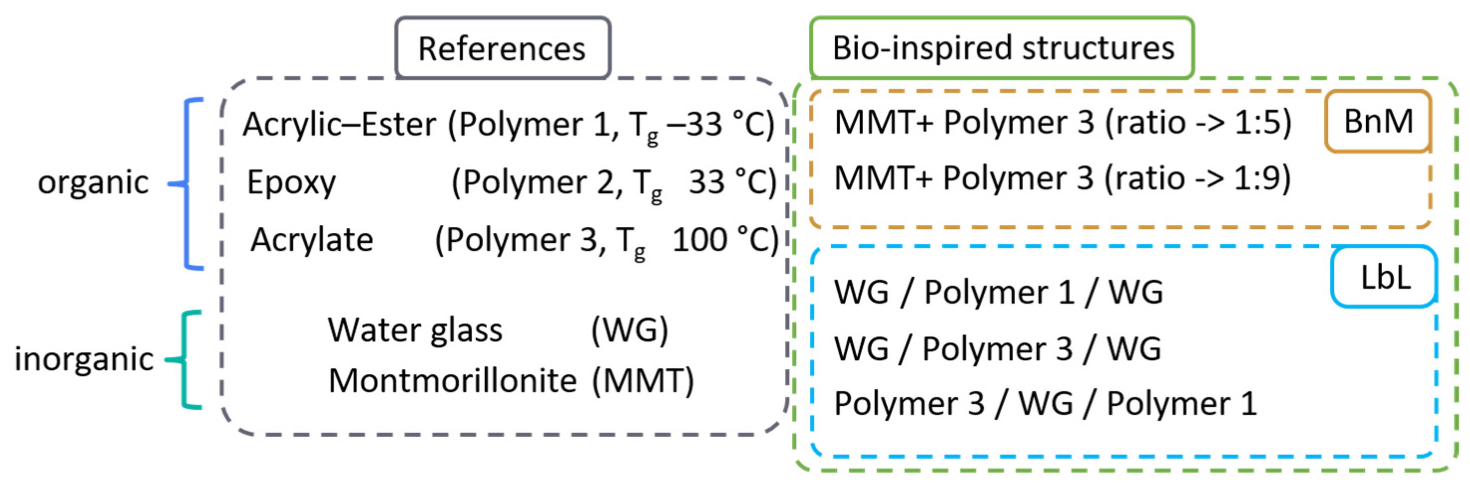
Aqueous dispersions and solvents (dissolved WG) of inorganic and organic materials were used to impregnate the rovings. The inorganic materials used were Cloisite-Na+, a sodium-based montmorillonite (MMT), from BYK-Chemie GmbH (Wesel, Germany) and Sodium Silicate (water glass, WG) from Otto Fischar GmbH & Co. KG (Saarbrücken, Germany). Organic components used were Mowilith LDM 7978 (Acrylic-Ester–Polymer 1) with a glass transition temperature of Tg = −33 °C from Celanese (Frankfurt, Germany), FILCO® 74,005 (Epoxy—Polymer 2) with Tg = 33 °C from C.O.I.M. S.p.A.—Chimica Organica Industriale Milanese (Offanengo, Italy), and Tecosit 1000 CC (Acrylate—Polymer 3) with Tg = 100 °C from CHT Germany GmbH (Tübingen, Germany). The Tg values were provided by the suppliers.
2.2. Methods
2.2.1. Preparation of Dispersions for the Impregnation Process
The impregnations were prepared and mixed in different ways. The montmorillonite (MMT) had to be prepared as a stable dispersion in water in order to achieve platelet separation for the self-assembling of the layered structure. All impregnations produced and used are shown schematically in Figure 1.
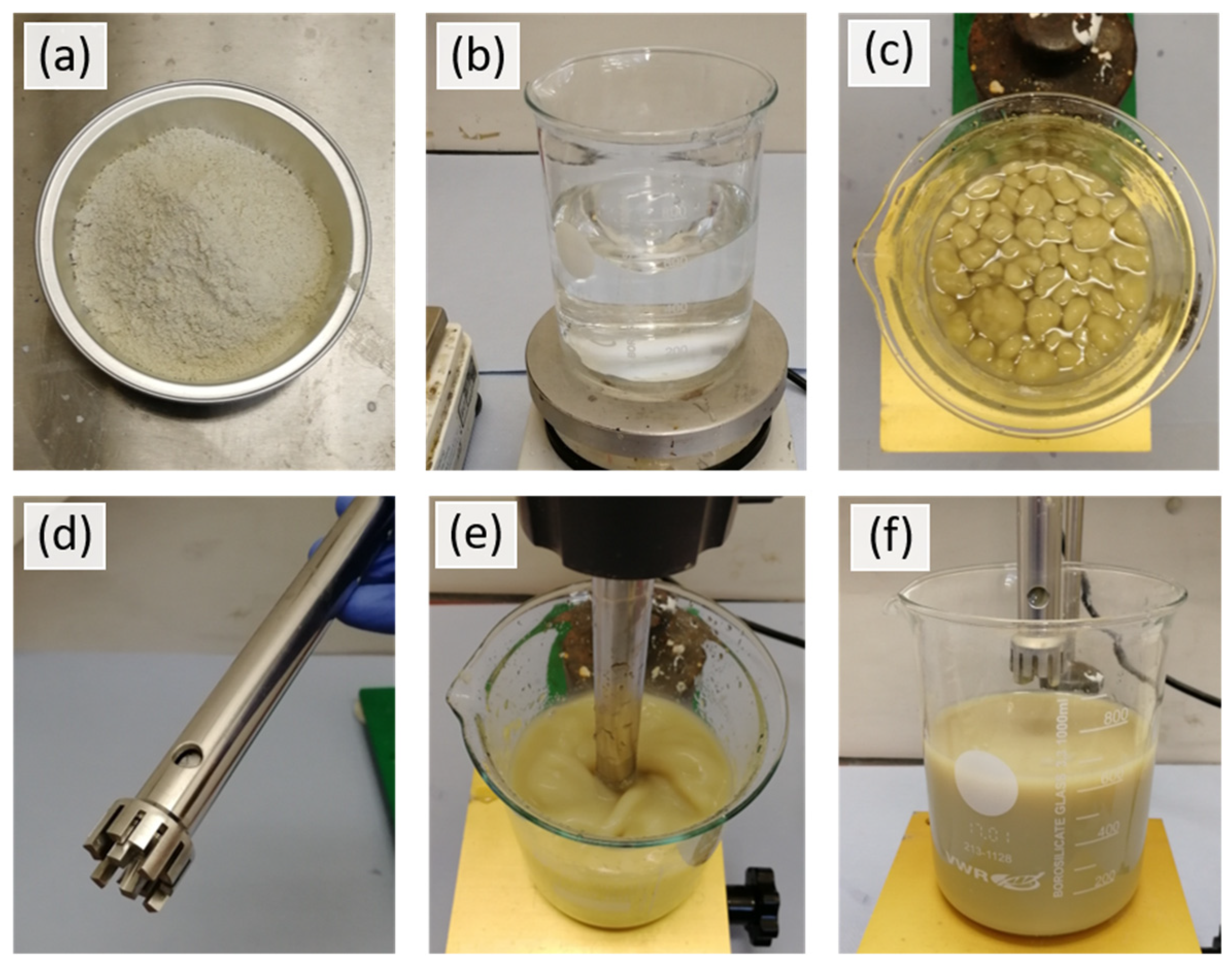
For the preparation of the MMT dispersion, pristine MMT powder was weighed and then added in portions into a beaker filled with de-ionized water under constant stirring at 200 rpm. Stirring was performed with a Heidolph MR 3001 magnetic stirrer from Heidolph Instruments GmbH & Co.KG (Schwabach, Germany) with the appropriate magnetic stirring bar. After all of the solids had been added, the speed was increased to approximately 600 rpm, and mixing was continued for a further 5 min. In most cases, a homogeneous dispersion could not be achieved during this mixing process. Therefore, an ULTRA-TURRAX®-T25 basic mixer from IKA®-Werke (Breisgau, Germany) was used for 15 min to break up coarse agglomerates: at first for approx. 3 min on speed 1 (6.500 rpm), and then the rest of the time at speed 2 (9.500 rpm). After disaggregation of the large agglomerates, the full beaker was treated in an ultrasonic bath at 25 kHz for 4 h. Due to the energy input of the ultrasonic treatment, the water in the ultrasonic bath that surrounded the filled beaker was heated up to approximately 80 °C. After 4 h, the filled beaker was removed from the ultrasonic bath and left to rest for use the next day. The complete process for preparing an 800 mL MMT nanoclay dispersion is shown in Figure 2.
All other impregnations were diluted with de-ionized water. The weight percentages of dispersed solids and the ratio used are listed in Table 2.
2.2.2. Roving Impregnation
For the impregnation of carbon fibers, a compact impregnation device was developed [61]. This device is specialized for mineral-impregnating suspension [28,62], but it is also suitable for polymer dispersions. The system is modularly designed for cleaning, transport, and quick adaptations to various test environments.
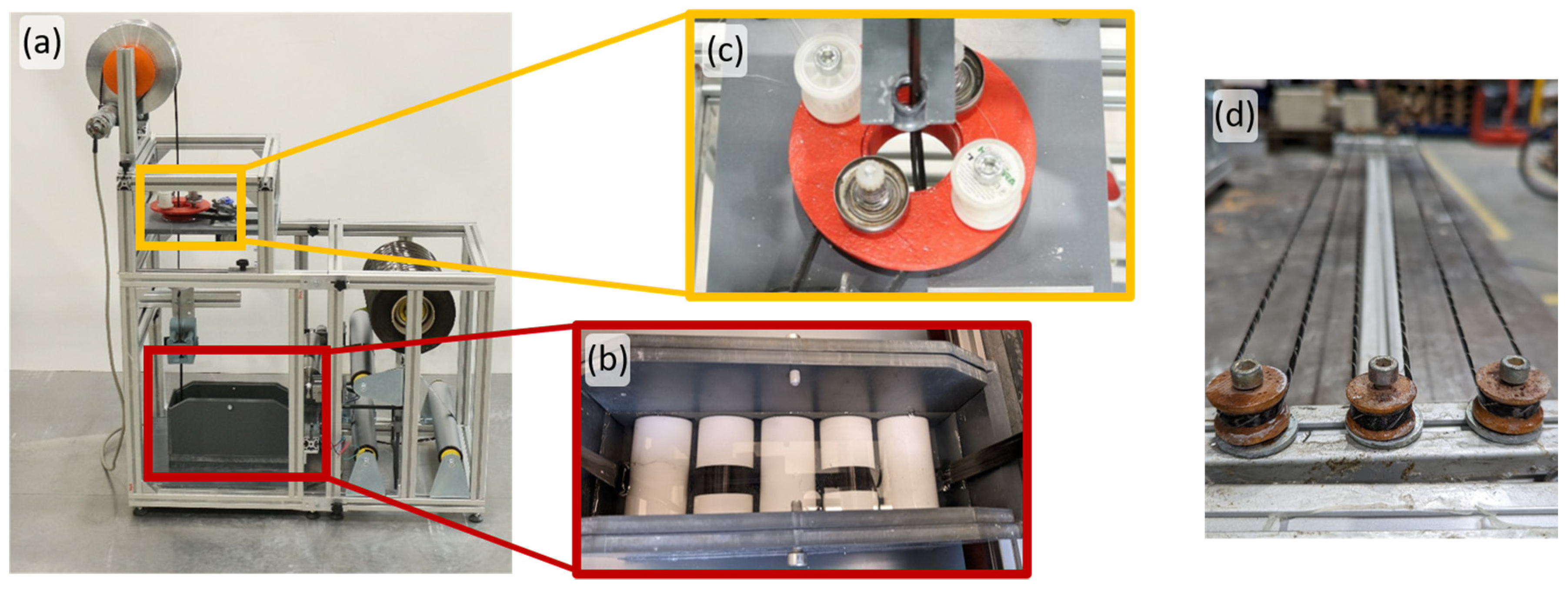
Accordingly, the compact impregnation device consists of four modules: the linearization module, the impregnation bath, the winding module, and the yarn take-off (Figure 3a, equipped with a yarn storage spool). In the first module, the linearization module, TOPOCHROM®-coated rollers, and curved guide rods are arranged to guide the yarn. While the microscopic spherical surface texture of the rollers protects the filaments from damage, the deflection via the rollers ensures the flattening and spreading of the fiber strand.
The yarn is systematically guided over a set of five PTFE-coated rollers, all immersed in the impregnation bath (Figure 3b). In this way, the curvature and spread of the yarn can be controlled in a targeted manner, and a uniform penetration of the different suspensions or dispersions can be ensured. After the impregnation bath, surplus suspension material on the yarn is removed by a conical nozzle integrated into the forming unit.
After completion of the final surface treatment of the yarn, facilitated by a latex membrane, it is then conveyed to the winding module. At this stage, a spiral winding process is carried out with the use of a taut cotton yarn. The objective of this process is twofold: to preserve the dense morphology of the impregnated yarn and to impart a gently undulating structure to the surface of the yarn (Figure 3c). Finally, the yarn can be fed directly to a further processing stage or temporarily stored on yarn spools. In this work, the yarn was stored on a reel and tightened to align the fibers (Figure 3d).
After the impregnated roving was mounted on the reel, it was placed in the oven at 160 °C for at least 30 min. The annealing process leads to the evaporation of the water and, at the same time, to the independent arrangement of the nanometer-sized solids and, if present, to the film formation of the organic components. Film formation here means that the organic components come into contact at the temperature described and coalesce to form a film. After sufficient annealing time, the reel with the impregnated roving was removed from the oven and allowed to cool to room temperature. The cured rovings were then removed from the reel and cut for the YPO.
2.2.3. Cross-Section Analysis
Small roving samples were taken to gain insight into the cross-section. The rovings used were taped (yellow tape) to prevent splaying of the roving ends during separation. This analysis can be used to determine roving geometry and impregnation quality. For this purpose, small roving parts cut to approx. 2 cm were attached to a plastic holder and poured with cold-curing embedding resin in a cylindrical mold. After curing, the samples were polished so that the roving cross-section could be easily observed under a reflected light microscope.
2.2.4. Thermogravimetric Analysis
Thermogravimetric analysis (TGA) was used to determine the sizing as well as impregnation contents. A TA Instruments Q500 low mass furnace (New Castle, DE, USA) was used to analyze samples up to 30 mg. Samples were heated to 500 °C in air atmosphere at a heating rate of 10 °C/min. The tests allow comparison of the rising temperatures as a function of the measured mass of each sample.
2.2.5. Fabrication of Test Specimens for the Yarn Pull-Out
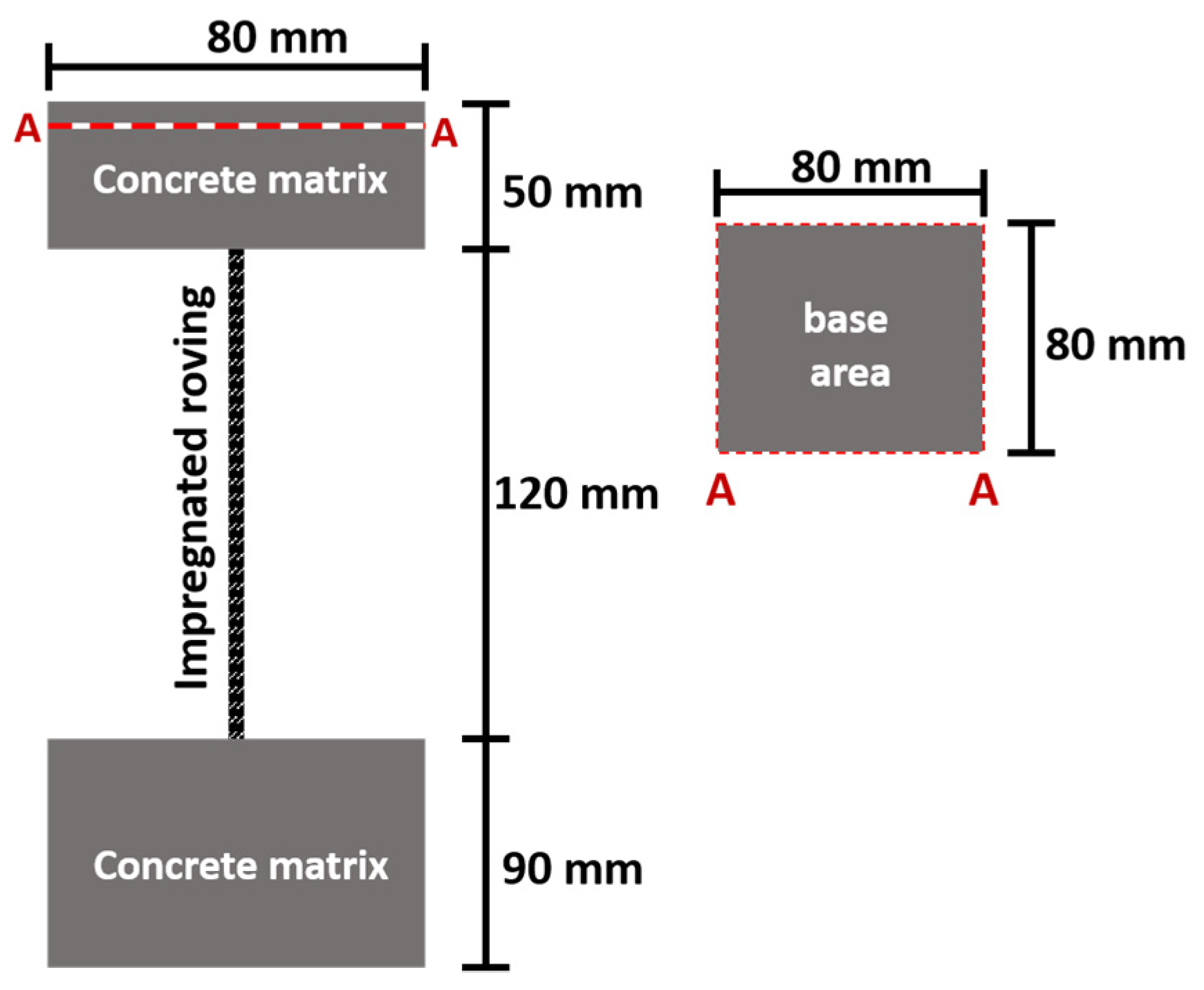
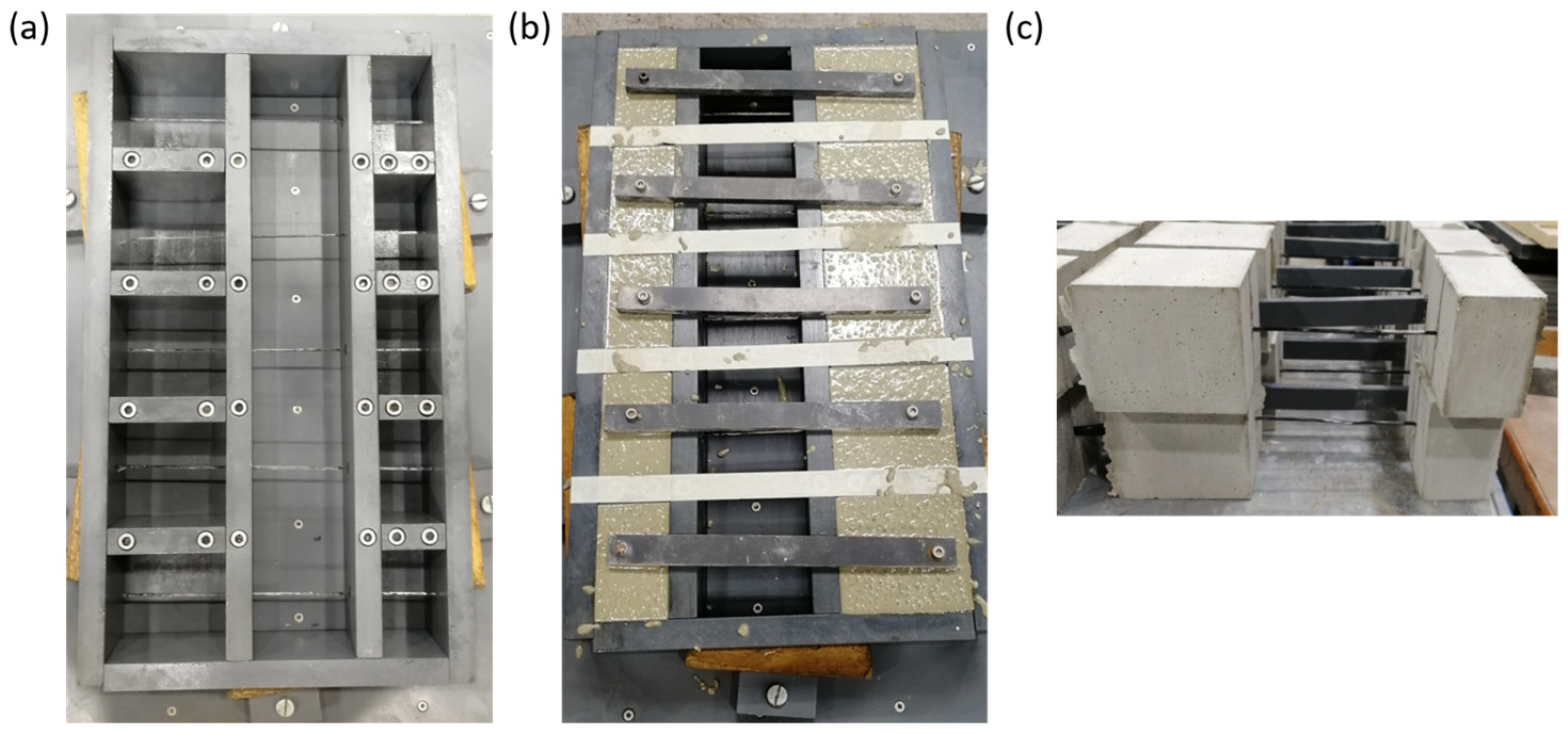
The fresh concrete described in Section 2.1.2. was used to prepare the YPO specimens, specifically their upper and lower cuboids, respectively. The exact dimensions are shown in Figure 4. First, the impregnated carbon rovings were fixed in the formwork (Figure 5a). After fresh concrete was produced, it was poured into the provided cavities (Figure 5b). After one day of curing, the YPO specimens reached green strength and could be demolded (Figure 5c).
2.2.6. Yarn Pull-Out
To characterize the bond between different impregnated carbon rovings and the concrete matrix, one-sided pull-out tests were conducted using a custom-designed setup and an INSTRON 8501 universal testing machine (Norwood, MA, USA). The yarn pull-out was carried out at a speed of 1 mm/min under normal climate condition. The force was recorded with a 20 kN load cell. For each variation of impregnation, 12-15 test specimens were prepared. This method and specimen preparation are well known and have been established in recent years in other works [27,28,63].
The coated rovings were embedded in SCC (Table 1), as shown in Figure 5b, and demolded after one day. Subsequently, the specimens were stored in a water bath at 20 °C for 7 days after fabrication. Following this, the specimens were further conditioned in a standard environment at 20 °C and 65% relative humidity until the age of 14 days, when they were tested.
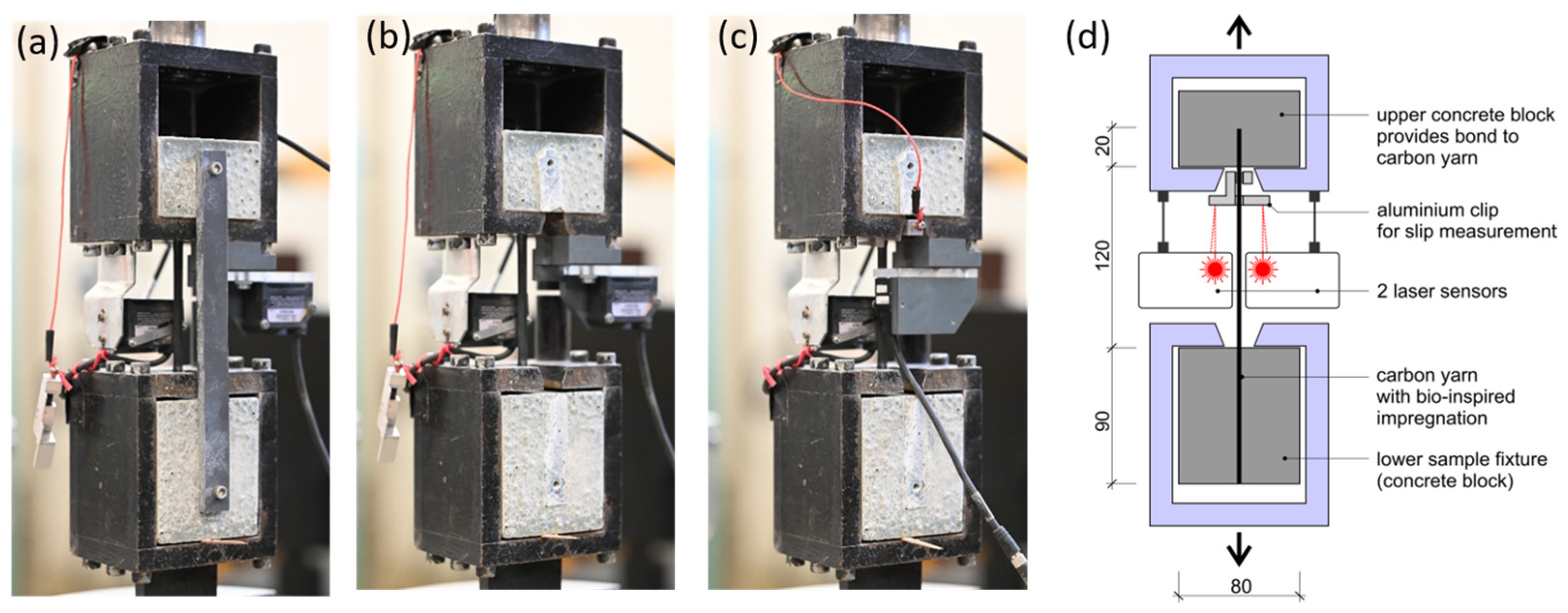
The setup of the pull-out test and the geometry of the specimens are schematically depicted in Figure 4 and Figure 6d. The embedment length of all carbon rods was 50 mm in the upper concrete block to avoid failure due to exceeding the tensile strength of the rods at room temperature. This length is also referred to as the embedding length. The lower concrete block, with an embedding length of 90 mm, served as an anchorage to initiate the pull-out force.
2.2.7. Microscopic Interphase Analyses
Digital microscopy, Keyence VHX-6000 from the company Keyence Deutschland GmbH (Leinfelden-Echterdingen, Germany), was used to further investigate the composite zone affected by the pull-out. For this purpose, the specimens were cut and split in the embedded region up to 1 cm before reaching the yarn. This cut eased the splitting of the embedded area, exposing both the yarn and the interphase, which were then visually analyzed.
3. Results and Discussions
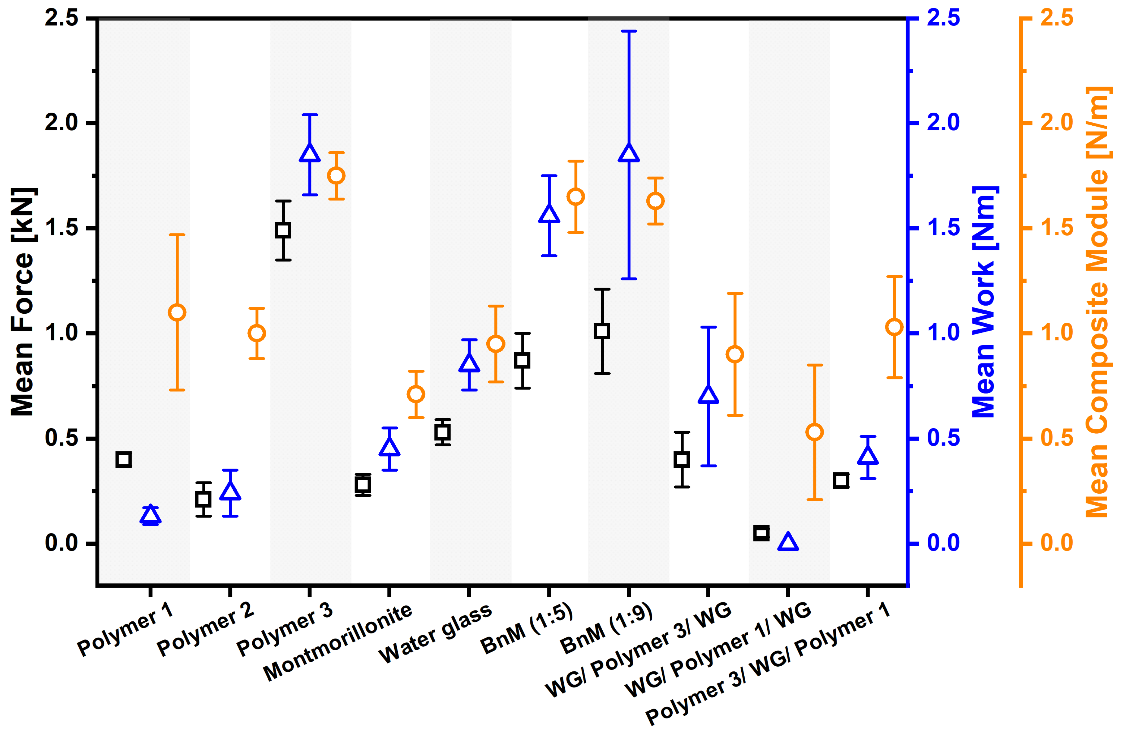
In order to evaluate the impregnation quality, the roving cross-sections produced were visually analyzed with the corresponding YPO graphs. The YPO was evaluated in terms of force maxima, pull-out work, and calculated bond modulus (BM), which was calculated after Schneider et al. [63]. The visual results of the roving cross-sections were then compared with those of the interphase between the impregnated carbon roving and the concrete matrix of the split test cuboids from which they were pulled out in order to draw further conclusions about the obtained quantitative results of the YPO. All measured and calculated values are shown in separate graphs, jointly in Figure 7, and listed in Table 3.
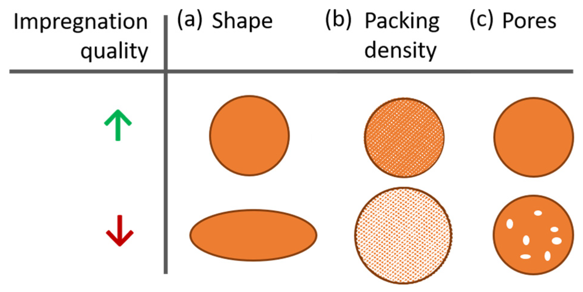
For a qualitative evaluation of the roving cross-sections, three important factors are assumed in this work (Figure 8). First is the shape factor, which describes the symmetry of the roving cross-section (Figure 8a). The more circular a roving is, the better, since a minimum number of exterior fibers are in contact with the matrix, and the forces acting on the interior fibers can be transferred more evenly due to the cross-section geometry. Second is the packing density (Figure 8b), which describes how densely a roving cross-section is filled with fibers. The higher the packing density (smaller distance between fibers), the smaller the roving circumference and the smaller the number of exterior fibers. The lower the packing density (greater distance between fibers), the larger the roving circumference, the greater the number of exterior fibers, and the greater the likelihood of the presence of defects such as pores. The third factor is the presence of imperfections such as pores (Figure 8c), which may not affect the roving circumference but have inhomogeneities that reduce uniform force distribution to all interior fibers.
The graphs of the YPO measurements reflect the force required over the displacement, where the displacement is defined as the distance by which the roving has been pulled out. The most important parameters in evaluating the YPO are the maximum force (Fmax) required, the performed work (W), and the calculated composite bond modulus (BM) [28,63]. Fmax describes the force required to completely debond the interphase between carbon fibers and the concrete matrix. The main focus was to ascertain only Fmax because not all curves in this work clearly indicate the necessary parameters for determining bond strength. The performed work was calculated up to a maximum pullout of 2.5 mm. It reflects the ratio of force required per displacement. BM indicates the stiffness of the composite and is displayed by the initial slope of the curve [28].
In addition, interphase analysis of the split pull-out cuboids provides further information on the bonding behavior of the impregnated rovings. Individual carbon fibers, fiber bundles, or the absence of carbon fibers can be observed. This allows conclusions to be drawn about the bonding properties of the impregnation to the concrete matrix.
3.1. Reference Impregnations
Among the solely organic impregnations (called “references”), large differences were found regarding the YPO results, the visually characterized roving cross-sections, and the TGA results. It was expected that with the same solid concentration in the dispersion of the impregnation bath, approximately the same amount of solids (Table 2) would be applied onto and into the roving. The polymers were selected based on their glass transition temperature (Tg) to influence the mechanical interphase behavior. A polymer’s Tg is its temperature range of the transition from a rigid glassy condition to a flexible rubbery up to sticky conditions. The Tg of the organic component is the critical parameter in determining the ductile properties of the composite as interphase. The lower the Tg, the more ductile a polymer behaves because above the Tg, the polymer chains are more flexible than below, where they are more rigid due to higher crystallinity and cross-linking density [66]. In other words, the polymers with a lower Tg were assumed to have a lower capability of stress transfer than polymers with a higher one. All Tg values have been provided by the polymer dispersion suppliers (see Section 2.1.3).
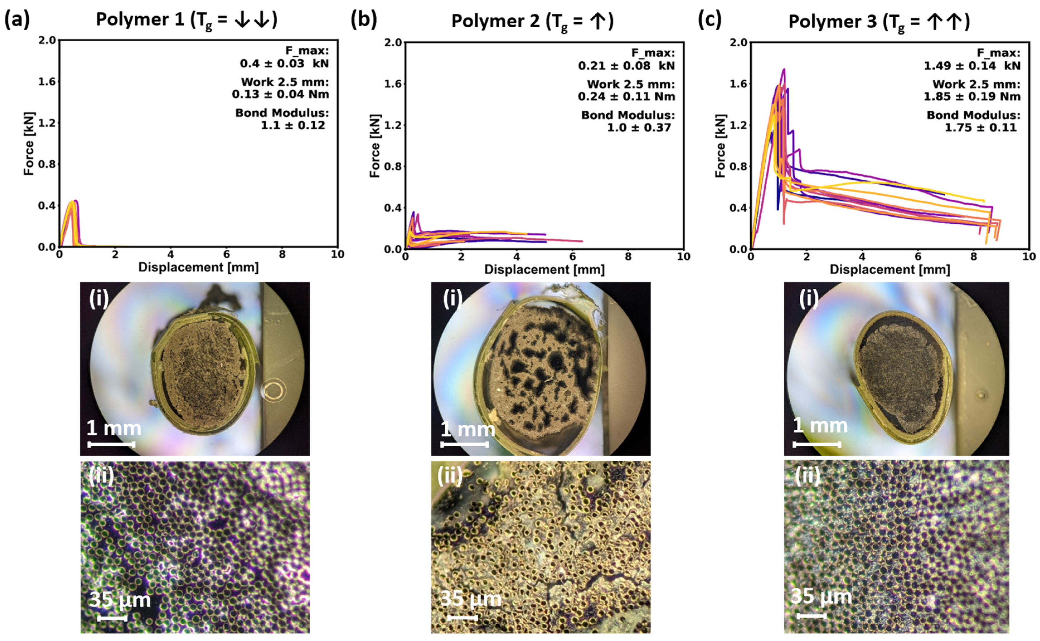
The lowest forces at the YPO were found for the rovings impregnated with Polymer 2 (Tg = ↑, Figure 9b). In comparison, rovings with the Polymer 1 (Tg = ↓↓, Figure 9a) impregnation achieved twice the average force maxima. The highest YPO values were achieved by rovings with a Polymer 3 (Tg = ↑↑, Figure 9c) impregnation. This is in contrast to the proven impregnation content of the rovings (TGA values in Table 3), where rovings impregnated with Polymer 2 (Tg = ↑) have more than twice the solid organic impregnation amount of Polymer 1 (Tg = ↓↓) and slightly less than a third of the measured solid content of the Polymer 3 (Tg = ↑↑) impregnation.
This may be due to the insufficient impregnation of the Polymer 2 dispersion, which resulted in a roving cross-section with large pores, as shown in Figure 9b(i). Despite the large number of exterior fibers, such a roving cross-section absorbs the forces applied to it unevenly and transfers them to the interior fibers in a correspondingly deficient manner. However, the Polymer 2 impregnation achieved a higher mean work, although the force maxima were lower. This can be related in part to the physical property described by the Tg [67]. Therefore, the Polymer 2 impregnation with a Tg of 33 °C was able to accomplish more performed pull-out work than the very sticky Polymer 1 with a Tg of −33 °C, which appeared to have too low of a frictional effect during pull-out. Also, other authors have described the strong influence of Tg on the stress transfer capability of the yarn matrix interphase and observed lower load transfer with decreasing Tg [68].
The values of the measured Fmax of the two polymers reveal that the bonding is not merely a function of the respective Tg because a higher Fmax would be expected for the stiffer polymer. The results furthermore suggest that the impregnation quality is dominant in affecting the YPOs and composite bond strength.
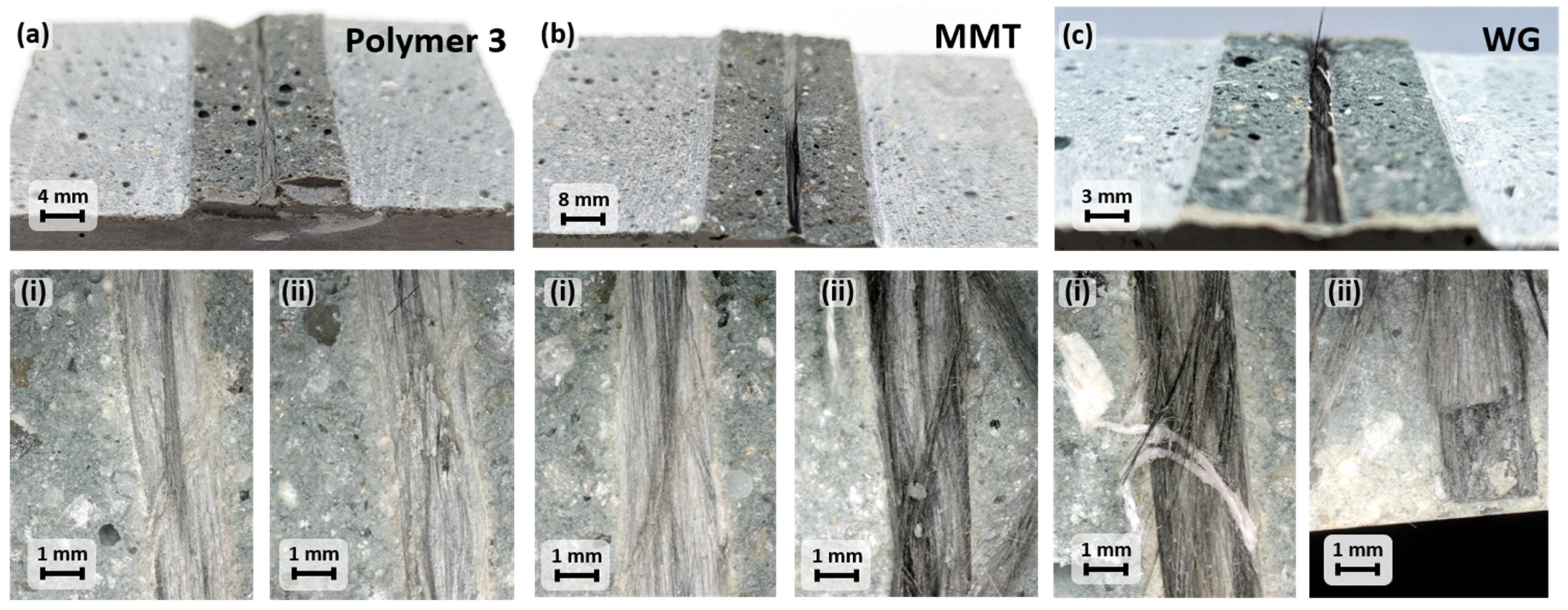
As described before, the YPOs of the rovings impregnated with the Polymer 3 (Tg = ↑↑) dispersion clearly achieved values with the highest Fmax, the largest performed work, and the highest BM. This can be attributed to the quality of the impregnation (Figure 9c(i,ii)) and the very high Tg of 100 °C. As described by Preinstorfer et al. [16], stiffer interphases can enhance the distribution of the applied forces among the fibers. However, this distribution can only be accomplished as long as a dense roving cross-section and uniform impregnation are ensured [19]. Comparison of the interphases of the split specimen (Figure 10—Polymer 3) suggests a sufficiently adhesive internal bonding and a lower insufficient external bond (contact zone of the concrete matrix for impregnation) since at the high YPO values obtained, only a few fibers remain in contact with the matrix.
The roving cross-sections of the sole mineral impregnations (MMT and WG) do not show any significant differences at first view. However, the WG impregnation (Figure 9b(i)) within the roving was insufficient and showed small internal fissures. The individual fiber cross-sections and the appearing spacing, the impregnation, can be seen in Figure 9a(ii), Figure 9b(ii), respectively.
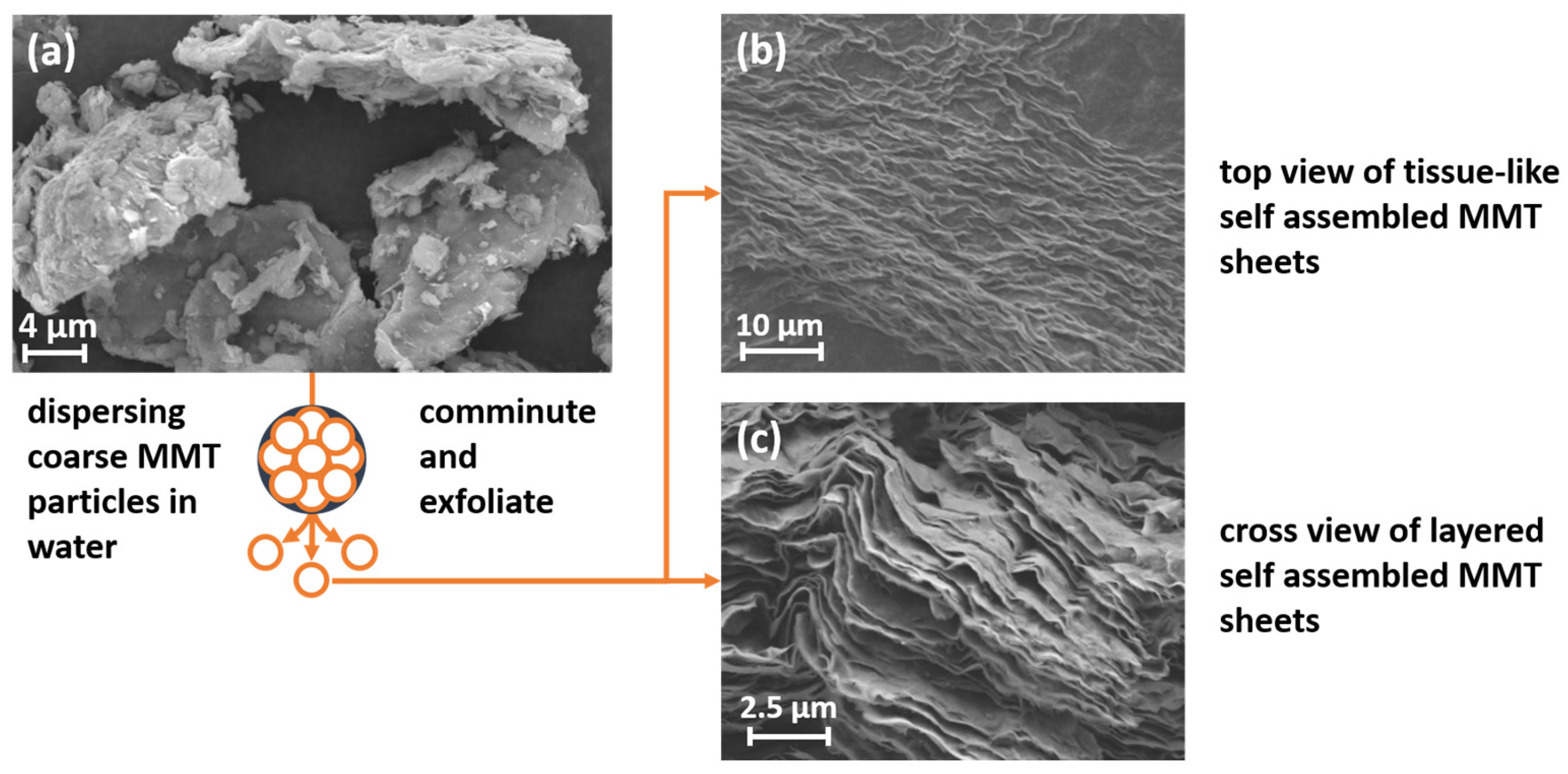
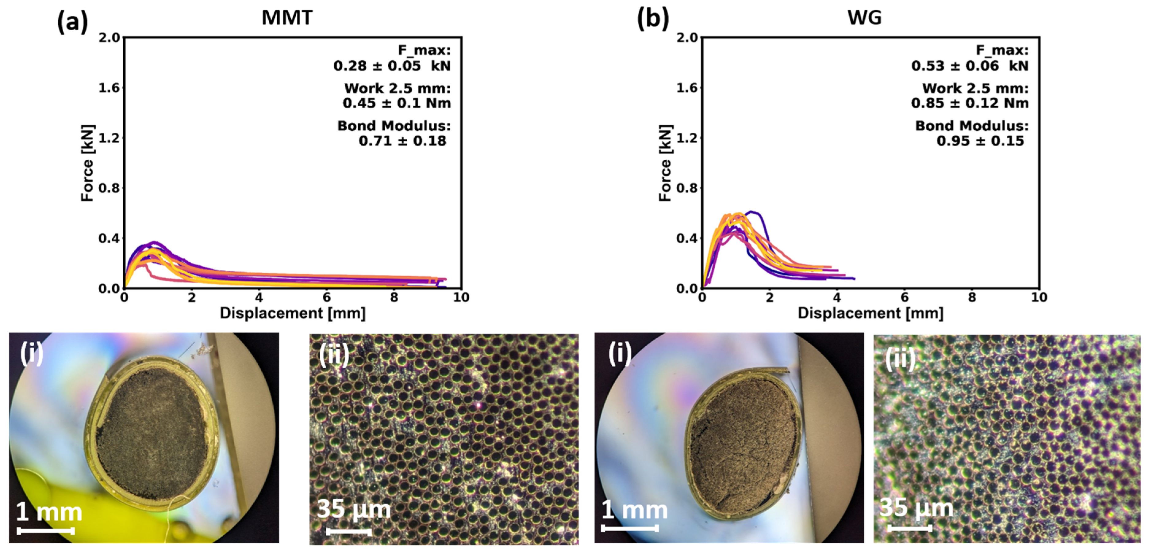
MMT nanoparticles are used as admixtures in concrete to induce additional nucleation [69]; they are chemically reactive, form increased C-S-H [69], and reduce the number of C-S-H gel pores to densify the matrix [70]. These beneficial properties of MMT in contact with the concrete matrix were expected to form a strong bond in the interphase. Based on the measured YPO values, it can be seen that rovings with the MMT impregnation exhibit very low Fmax and therefore very low performed works than the WG impregnation. This is primarily due to the structure and shape of the minerals in the impregnation. MMT is a platelet-shaped mineral with different surface and edge charges. The surfaces are negatively charged, and the edges are positively charged [71]. Once the coarse powder (Figure 11a) has been successfully dispersed in water, which includes being comminuted and exfoliated into individual platelets, these individual platelets form a self-assembly (stacked) layer structure during the drying process (Figure 11b,c) in which the layers are loosely connected. Therefore, they do not inhibit the crack growth in the interphase and might even slide off each other in the dried state [72]. However, fibers were detected in the interphases of the split concrete specimen (Figure 10-MMT). This indicates a properly bonded impregnation due to its reactivity toward the concrete matrix.
WG, on the other hand, exhibited almost twice the Fmax, higher performed works, and a higher BM. However, the analyzed and calculated values for mineral impregnation are far below the comparative values of mineral-based impregnations presented by, e.g., Schneider et al. [63]. Typically, WG is added to the concrete mixture to promote the degree of hydration of the concrete mix and to obtain a higher proportion of C-S-H gel. It acts as a nano-filler for the pores of the concrete, compacts it, and increases its early strength due to its high pozzolanic activity [73,74]. These properties should cause WG to react in contact with the concrete matrix and form a stronger bond than, for example, polymeric impregnations. This is best seen in the splitting tests shown in Figure 10 WG-(c) (i) and (ii). As WG dissolves in an alkaline environment [75], it chemically reacts with the concrete matrix. This results in improved bonding of the WG-impregnated carbon rovings to the concrete matrix, as evidenced by the numerous carbon roving residues within the interphase after the pull-out test. Although successful binding was achieved, the Fmax (Figure 12b) values remained below those of, e.g., Polymer 3 (Figure 8).
This indicates that there was a proper bond at the contact zone between the impregnation and the concrete matrix, but the applied force could not be transferred to the interior fibers due to the stiff and brittle mineral. With the mineral coatings used by Schneider et al. [63], it can be assumed that at least a slight displacement of the filaments was possible without complete damage to the filament–filament contact.
3.2. Analysis of the Bio-Inspired Impregnations
Following the evaluation of the reference materials, the YPO results of the bio-inspired interphase were analyzed. As explained at the beginning, the structure of the nacre layer or the individual filaments of the glass sponge has an enormous influence on the mechanical properties. The alternation of inorganic and organic phases, whether spatially separated (LbL) or intermixed (BnM), is expected to result in higher toughness and strength due to targeted crack elongation and arrest of developing cracks [50].
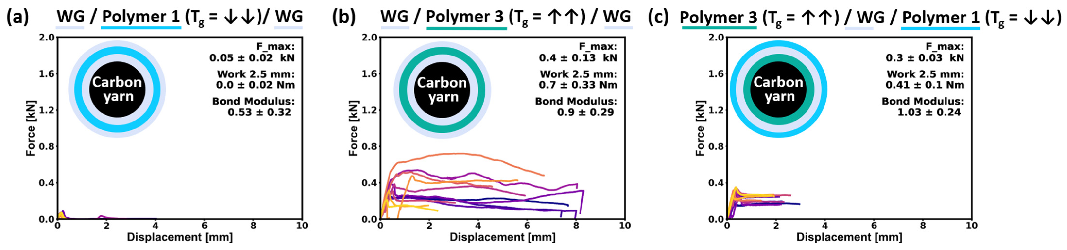
The results of LbL structures are shown in Figure 13. Two strategies were considered during sample preparation: (i) a sandwich-like multilayer system (LbL-system) with WG as full impregnation of the whole roving cross-section and therefore as a primer and as final coating layer with the Polymer 1 (Tg = ↓↓) and Polymer 3 (Tg = ↑↑) as the intermediate coating layer (Figure 13a,b); (ii) an impregnation with the Polymer 3 (Tg = ↑↑) as full impregnation followed by coating layers of WG and the Polymer 1 (Tg = ↓↓) (Figure 13c).
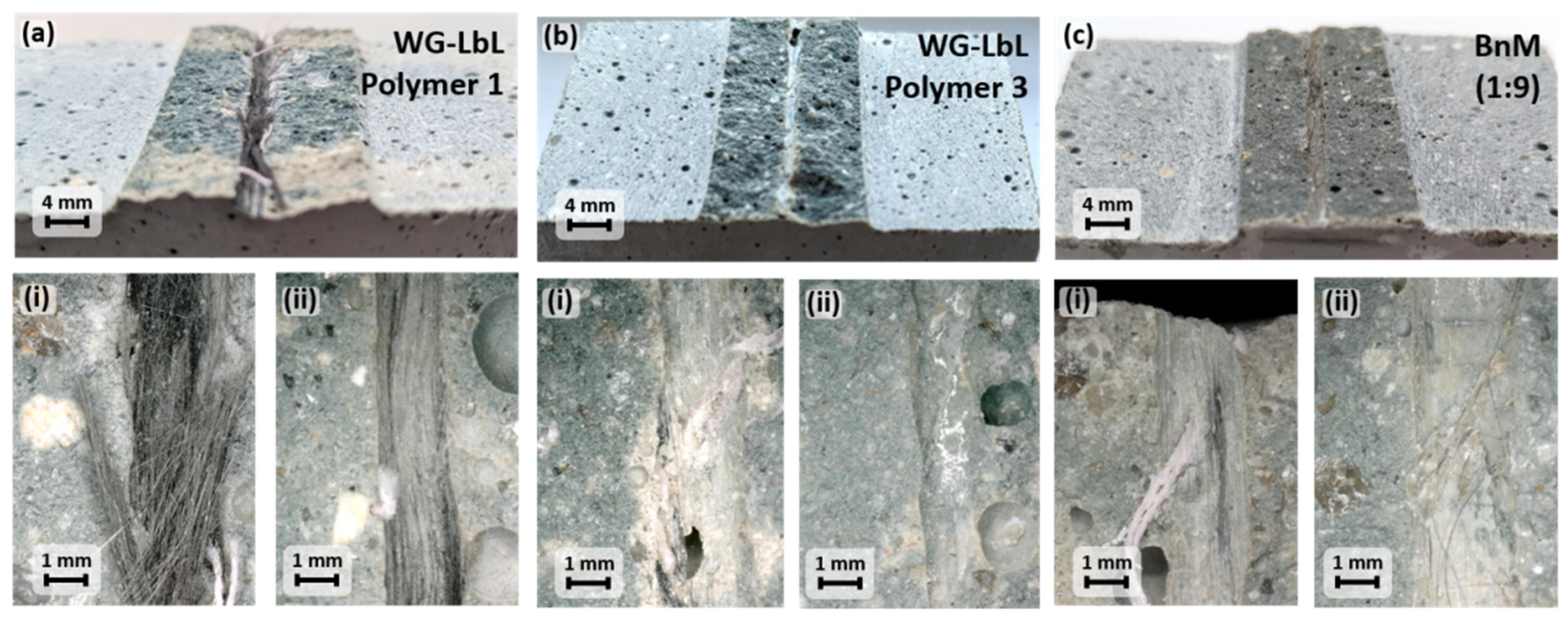
As the reference measurements show, the Polymer 1 (Tg = ↓↓) LbL-system surrounded by WG performs so poorly that hardly any forces can be measured. This contributes to the results found for using pure Polymer 1 impregnation (Figure 8a) that revealed low stress-transfer capability. Splitting of the concrete cube after the YPO test revealed a large number of residual carbon fibers (Figure 14—Polymer 1), as also observed for the reference interphase of the WG-YPO test specimen (Figure 10—WG), indicating a stronger bonding of the top layer of WG to the concrete matrix than to the other layers. It can therefore be concluded that the layer of Polymer 1 (Tg = ↓↓) forms the weakest bond in the layer systems and is responsible for the low performance. A different behavior was obtained with the LbL system using Polymer 3 (Tg = ↑↑). Separation of the two WG layers was achieved in the coating layer of Polymer 3, as only a glossy residual layer of the outer WG coating without carbon fibers could be detected on the split cuboid (Figure 14—Polymer 3). In contrast to the use of Polymer 1, the high Tg of Polymer 3 enables an enhanced stress transfer in the interphase, whereby the layered structure leads to a pronounced ductile instead of brittle failure.
The YPO results of the LbL structure made by Polymer 3 (Tg = ↑↑)/WG/Polymer 1 (Tg = ↓↓) (Figure 13c) demonstrate again that the implementation of the “weak” layer of Polymer 1, which was used as the exterior coating in contact with the concrete matrix, leads to overall low pull-out performance. The stress-transfer capability of the whole LbL-structure was reduced, although Polymer 3 was employed as impregnation, showing dense and pore-free roving cross-sections (Figure 9c(i,ii)). This very first work of using bio-inspired LbL structures revealed a strong dependency on the selected polymer as well as the arrangement of the layers. In order to achieve improved mechanical behavior in LbL-inspired interphase structures, the interactions between the individual layers and the outermost layer in contact with the concrete matrix play a major role and offer the potential for improvement via chemical modification in the contact zones of the alternating coating layers.
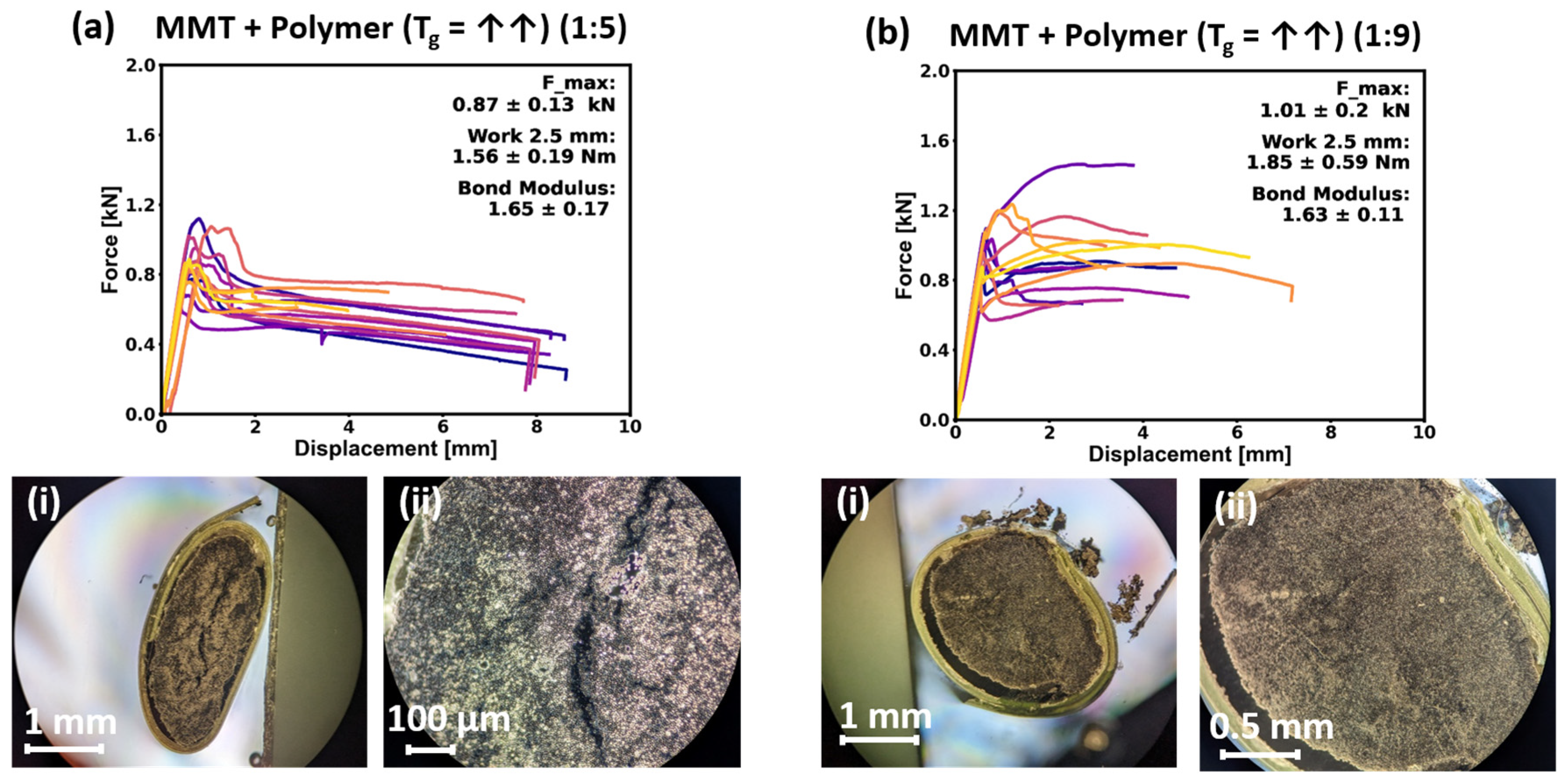
In the bio-inspired BnM structure, the mineral platelets (MMT) were combined with a surrounding polymer matrix. In this case, only Polymer 3 was selected for the preparation of the BnM-coatings; however, the Polymer:MMT ratio varied between 1:5 and 1:9.
The visual analysis shows differently shaped roving cross-sections (Figure 15a(i,ii),b(i,ii)). On the one hand, the roving impregnated with an MMT+Polymer 3 (Tg = ↑↑) mixing ratio of 1:5 formed a very wide and oval shape (Figure 15a(i)), and on the other hand, the one with a mixing ratio of 1:9 appears to have a more circular and slighter oval shape (Figure 15b(i)). The reason for the formation of different cross-sectional shapes is not clear so far but is assumed to be a result of the wetting, penetration, and viscosity conditions depending on the MMT particle amount. Except for pores in the 1:5 BnM impregnation (Figure 15a(ii)), both impregnated BnM structured rovings show dense fiber packing, indicating good impregnation as a prerequisite for adequate stress transfer between the inner filaments. This was displayed by the YPO results. The achieved Fmax and calculated BM for the BnM-structured impregnations were slightly lower compared to the reference values of Polymer 3. However, with the BnM impregnation MMT + Polymer 3 (Tg = ↑↑) in a ratio of 1:9, an equally high pull-out work was achieved as with the Polymer 3 (Tg = ↑↑) reference. The force–displacement curves show that the abrupt force reduction found for Polymer 3 after reaching Fmax, indicating a brittle failure, did not occur if MMTs were introduced in the interphase structure. In some cases, even further increases in the force with increasing displacement could be observed. The chemical bond that is achieved by adding the MMTs improves the interaction with the concrete matrix, but the layered MMT structure (an example is given in Figure 11c) contributes to the transfer of the stresses to the outer and inner filaments of the yarn. Therefore, no abrupt debonding and increased ductility enhanced by increasing the amount of MMTs was observed (Figure 15).
The visual analysis of the split shows only a lustrous surface with single carbon fibers. This means a strong internal adhesion between the fibers and the impregnation. Since no abrupt force drop was revealed during YPO, a strong interaction between impregnated yarn and concrete is assumed, even though the number of carbon fibers in the split sample was low. By adjusting the ratio of stiff polymer dispersion in combination with MMT nanoparticles, the brittle fracture behavior of Polymer 3 was reduced (Figure 9c). In future work, investigations will be carried out to optimize the MMT/Polymer 3 ratio with the aim of achieving higher force maxima and composite toughening.
4. Summary and Outlook
This paper presents the implementation of first-principle experiments to influence the bonding between impregnated carbon fiber reinforcements with respect to higher toughness by using layered structures inspired by nature. The focus of this work was on the use of layered polymer impregnations of varying stiffness in combination with brittle inorganic layer structures, whereby their reactivity with the concrete matrix, in addition to the geometric arrangement, was decisive for their selection. It was shown that especially the use of a stiff polymer containing self-assembled MMTs leads to advantageous results. This approach shows great potential for improvement by further adapting the interphase chemistry and morphology, e.g., by other types of polymers with Tg above 30 °C and adaption of layer thickness, size, and aspect ratio of nanoclay platelets, as well as their functionalization.
In the case of the LbL structure, hardly any improvement in the pull-out behavior could be achieved. The reasons are seen in the insufficient formation of the LbL structure, but above all, in the fact that an initial impregnation with WG leads to too brittle of a connection of the inner filaments and thus to a low stress transfer. In principle, the combination with the stiff polymer dispersion (Tg = 100 °C) led to a higher pull-out work. The application of a polymer layer with Tg = −33 °C is equivalent to the incorporation of a failure zone, so this case results in low performance. The combination of stiffer polymer coatings and WG offers the potential for improved pull-out performance; however, in terms of manufacturing, these layer structures require multiple coating and drying steps and are therefore very costly in terms of time and energy.
The main findings of this study can be summarized as follows:
- -
- The stress-transfer capability of the fiber-matrix bond zone is dominated by the polymer stiffness rather than the polymer amount.
- -
- The combination of organic and inorganic components in layered interphase structures offers a promising route to avoid brittle failure and to pronounce ductile failure instead, whereby BnM structures were more effective and also easier to apply than LbL structures. Although polymers in nature with low stiffness are used to connect the inorganic layers, a beneficial effect regarding ductility could only be observed by using a stiff, high-Tg polymer.
- -
- The introduction of layered inorganic components in the polymers leads to an improved bond with the concrete matrix and might also contribute to avoiding spalling of concrete layers if used for the impregnation of textile reinforcing structures in CFRC. This study supports the development of new bioinspired impregnations for the enhanced mechanical performance of lightweight, textile-reinforced concrete parts.
Author Contributions
Conceptualization, T.U., T.N., V.M. and C.S.; methodology, T.U., T.N. and C.S.; software, T.U. and T.N.; validation, T.U., T.N. and C.S.; formal analysis, T.U., T.N. and C.S.; investigation, T.U., T.N. and C.S.; data curation, T.U.; writing—original draft preparation, T.U. and T.N.; writing—review and editing, T.U., T.N., V.M. and C.S.; visualization, T.U. and T.N.; supervision, V.M. and C.S.; project administration, C.S.; funding acquisition, V.M. and C.S. All authors have read and agreed to the published version of the manuscript.
Funding
The authors would like to thank the German Research Foundation (Deutsche Forschungsgemeinschaft—DFG) for financial support; this work was part of the Sonderforschungsbereich/Transregio 280 (SFB/TRR 280) “Konstruktionsstrategien für materialminimierte Carbonbetonstrukturen”/”Design Strategies for Material-Minimized Carbon Reinforced Concrete Structures” under the project-ID 417002380.
Data Availability Statement
The data presented in this study are available upon request from the corresponding authors. The data are not publicly available due to ongoing study.
Conflicts of Interest
The authors declare no conflict of interest. The funders had no role in the design of the study; in the collection, analyses, or interpretation of data; in the writing of the manuscript; or in the decision to publish the results.
References
- Preinstorfer, P.; Kromoser, B.; Kollegger, J. Flexural behaviour of filigree slab elements made of carbon reinforced UHPC. Constr. Build. Mater. 2019, 199, 416–423. [Google Scholar] [CrossRef]
- Hegger, J. Handbuch Carbonbeton: Einsatz Nichtmetallischer Bewehrung; Wilhelm Ernst & Sohn Verlag fur Architektur und Technische: Newark, NJ, USA, 2023; ISBN 9783433608685. [Google Scholar]
- Scholzen, A.; Chudoba, R.; Hegger, J. Dünnwandiges Schalentragwerk aus textilbewehrtem Beton. Beton-Stahlbetonbau 2012, 107, 767–776. [Google Scholar] [CrossRef]
- Mechtcherine, V. Novel cement-based composites for the strengthening and repair of concrete structures. Constr. Build. Mater. 2013, 41, 365–373. [Google Scholar] [CrossRef]
- Holschemacher, K. Application of Textile Reinforced Concrete in Precast Concrete Industry. IOP Conf. Ser. Mater. Sci. Eng. 2020, 753, 42086. [Google Scholar] [CrossRef]
- Erhard, E.; Weiland, S.; Lorenz, E.; Schladitz, F.; Beckmann, B.; Curbach, M. Anwendungsbeispiele für Textilbetonverstärkung. Beton-Stahlbetonbau 2015, 110, 74–82. [Google Scholar] [CrossRef]
- Sharma, M.; Gao, S.; Mäder, E.; Sharma, H.; Wei, L.Y.; Bijwe, J. Carbon fiber surfaces and composite interphases. Compos. Sci. Technol. 2014, 102, 35–50. [Google Scholar] [CrossRef]
- Friese, D.; Scheurer, M.; Hahn, L.; Gries, T.; Cherif, C. Textile reinforcement structures for concrete construction applications––A review. J. Compos. Mater. 2022, 56, 4041–4064. [Google Scholar] [CrossRef]
- Scheerer, S.; Chudoba, R.; Garibaldi, M.P.; Curbach, M. Shells Made of Textile Reinforced Concrete—Applications in Germany; International Association for Shell and Spatial Structures (IASS): Madrid, Spain, 2017. [Google Scholar]
- Mechtcherine, V.; Schneider, K.; Brameshuber, W. Mineral-based matrices for textile-reinforced concrete. In Textile Fibre Composites in Civil Engineering; Elsevier: Amsterdam, The Netherlands, 2016; pp. 25–43. ISBN 9781782424468. [Google Scholar]
- Quadflieg, T.; Leimbrink, S.; Gries, T.; Stolyarov, O. Effect of coating type on the mechanical performance of warp-knitted fabrics and cement-based composites. J. Compos. Mater. 2018, 52, 2563–2576. [Google Scholar] [CrossRef]
- Schütze, E.; Curbach, M. Zur experimentellen Charakterisierung des Verbundverhaltens von Carbonbeton mit Spalten als maßgeblichem Versagensmechanismus. In Az Európai Unió Fejlődésének Alapismeretei; Klára, S., Ed.; Savaria University Press: Szombathely, Hungary, 2012. [Google Scholar]
- Lorenz, E. Endverankerung und Übergreifung Textiler Bewehrungen in Betonmatrices. Ph.D. Thesis, Technische Universität Dresden, Dresden, Germany, 2015. [Google Scholar]
- Krueger, M. Vorgespannter Textilbewehrter Beton; Universität Stuttgart: Stuttgart, Germany, 2004. [Google Scholar]
- Kulas, C.H. Zum Tragverhalten Getränkter Textiler Bewehrungselemente für Betonbauteile; RWTH Aachen University: Aachen, Germany, 2013. [Google Scholar]
- Preinstorfer, P.; Kromoser, B.; Kollegger, J. Kategorisierung des Verbundverhaltens von Textilbeton. Bauingenieur 2019, 94, 416–424. [Google Scholar] [CrossRef]
- Tepfers, R. Cracking of concrete cover along anchored deformed reinforcing bars. Mag. Concr. Res. 1979, 31, 3–12. [Google Scholar] [CrossRef]
- Cherif, C. Textile Werkstoffe für den Leichtbau; Springer: Berlin/Heidelberg, Germany, 2011. [Google Scholar]
- Jesse, F.; Curbach, M. Verstärken mit Textilbeton. In Beton-Kalender 2010; John Wiley & Sons, Ltd.: Hoboken, NJ, USA, 2010; pp. 457–565. [Google Scholar]
- Pocius, A.V. Adhesion and Adhesives Technology: An Introduction, 4th ed.; Hanser: Munich, Cincinnati, OH, USA, 2021; ISBN 9781569908501. [Google Scholar]
- Jan, H. Multiaxiale Gelege auf Basis der Kettenwirktechnik–Technologie für Mehrschichtverbunde Mit Variabler Lagenanordnung. Ph.D. Thesis, Technische Universität Dresden, Dresden, Germany, 2010. [Google Scholar]
- Pizzi, A.; Mittal, K.L. Handbook of Adhesive Technology, 3rd ed.; CRC Press Taylor & Francis Group: Boca Raton, FL, USA; London, UK; New York, NY, USA, 2018; ISBN 9781498736473. [Google Scholar]
- Kim, J.-K.; Mai, Y.-W. Engineered Interfaces in Fiber Reinforced Composites, 1st ed.; Elsevier Sciences: Amsterdam, The Netherlands; New York, NY, USA, 1998; ISBN 9780080530970. [Google Scholar]
- Moro, J.L. Baukonstruktion-Vom Prinzip zum Detail: Band 3 Umsetzung; Springer: Berlin/Heidelberg, Germany, 2009. [Google Scholar]
- Packham, D.E. Handbook of Adhesion, 2nd ed.; Wiley: Chichester, UK, 2005; ISBN 9780470014219. [Google Scholar]
- Da Silva, L.F.M.; Öchsner, A.; Adams, R.D. Handbook of Adhesion Technology; Springer: Berlin/Heidelberg, Germany; Cham, Switzerland, 2011; ISBN 9783642011689. [Google Scholar]
- Wilhelm, K. Verbundverhalten von Mineralisch und Polymer Gebundenen Carbonbewehrungen und Beton bei Raumtemperatur und Erhöhten Temperaturen bis 500 °C. Ph.D. Thesis, Technische Universität Dresden, Dresden, Germany, 2021. [Google Scholar]
- Schneider, K.; Michel, A.; Liebscher, M.; Terreri, L.; Hempel, S.; Mechtcherine, V. Mineral-impregnated carbon fibre reinforcement for high temperature resistance of thin-walled concrete structures. Cem. Concr. Compos. 2019, 97, 68–77. [Google Scholar] [CrossRef]
- Elias, H.-G. 6. Vollständig Überarbeitete Auflage. In Makromoleküle: Band 4: Anwendungen von Polymeren; Wiley-VCH: Weinheim, Germany, 2009; ISBN 9783527626540. [Google Scholar]
- Gruber, E. Polymerchemie: Eine Einführung in Die Chemie und Physikalische Chemie der Makromoleküle; Dietrich Steinkopff: Heidelberg, Germany, 1980; ISBN 9783642853043. [Google Scholar]
- Schleser, M. Einsatz polymerimprägnierter, alkaliresistenter Glastextilien zur Bewehrung zementgebundener Matrices. In Aachener Berichte Fügetechnik; RWTH Aachen University: Aachen, Germany, 2008. [Google Scholar]
- Albena, B. Untersuchungen zur Filmbildung Wäßriger Kunststoffdispersionen; FDC: Singapore, 2000. [Google Scholar]
- Kaiser, W. Kunststoffchemie für Ingenieure: Von der Synthese bis zur Anwendung; Hanser: München, Germany, 2021; ISBN 9783446466029. [Google Scholar]
- Elias, H.-G. 6. vollständig überarbeitete Auflage. In Makromoleküle: Band 1: Chemische Struktur und Synthesen; Wiley-VCH: Weinheim, Germany, 2009; ISBN 9783527626489. [Google Scholar]
- Zhang, Z.; Mu, Z.; Wang, Y.; Song, W.; Yu, H.; Zhang, S.; Li, Y.; Niu, S.; Han, Z.; Ren, L. Lightweight Structural Biomaterials with Excellent Mechanical Performance: A Review. Biomimetics 2023, 8, 153. [Google Scholar] [CrossRef] [PubMed]
- Barthelat, F.; Yin, Z.; Buehler, M.J. Structure and mechanics of interfaces in biological materials. Nat. Rev. Mater. 2016, 1, 16007. [Google Scholar] [CrossRef]
- Libonati, F.; Buehler, M.J. Advanced Structural Materials by Bioinspiration. Adv. Eng. Mater. 2017, 19, 1600787. [Google Scholar] [CrossRef]
- Monn, M.A.; Vijaykumar, K.; Kochiyama, S.; Kesari, H. Lamellar architectures in stiff biomaterials may not always be templates for enhancing toughness in composites. Nat. Commun. 2020, 11, 373. [Google Scholar] [CrossRef] [PubMed]
- Fratzl, P.; Weinkamer, R. Nature’s hierarchical materials. Prog. Mater. Sci. 2007, 52, 1263–1334. [Google Scholar] [CrossRef]
- Sun, J.; Bhushan, B. Hierarchical structure and mechanical properties of nacre: A review. RSC Adv. 2012, 2, 7617. [Google Scholar] [CrossRef]
- Fernandes, M.C.; Aizenberg, J.; Weaver, J.C.; Bertoldi, K. Mechanically robust lattices inspired by deep-sea glass sponges. Nat. Mater. 2021, 20, 237–241. [Google Scholar] [CrossRef]
- Li, Q.-W.; Sun, B. How to Surpass the Deep-Sea Glass Sponges Mechanically. Preprints 2021, 2021120042. [Google Scholar] [CrossRef]
- He, M.; Li, Y.; Yin, J.; Sun, Q.; Xiong, W.; Li, S.; Yang, L.; Hao, L. Compressive performance and fracture mechanism of bio-inspired heterogeneous glass sponge lattice structures manufactured by selective laser melting. Mater. Des. 2022, 214, 110396. [Google Scholar] [CrossRef]
- Li, Q.-W.; Sun, B.-H. Optimization of a lattice structure inspired by glass sponge. Bioinspir. Biomim. 2022, 18, 016005. [Google Scholar] [CrossRef]
- Maurizi, M.; Gao, C.; Berto, F. Inverse design of truss lattice materials with superior buckling resistance. NPJ Comput. Mater. 2022, 8, 247. [Google Scholar] [CrossRef]
- Li, L.; Guo, C.; Chen, Y.; Chen, Y. Optimization design of lightweight structure inspired by glass sponges (Porifera, Hexacinellida) and its mechanical properties. Bioinspir. Biomim. 2020, 15, 36006. [Google Scholar] [CrossRef]
- Woesz, A.; Weaver, J.C.; Kazanci, M.; Dauphin, Y.; Aizenberg, J.; Morse, D.E.; Fratzl, P. Micromechanical properties of biological silica in skeletons of deep-sea sponges. J. Mater. Res. 2006, 21, 2068–2078. [Google Scholar] [CrossRef]
- Aizenberg, J.; Weaver, J.C.; Thanawala, M.S.; Sundar, V.C.; Morse, D.E.; Fratzl, P. Skeleton of Euplectella sp.: Structural hierarchy from the nanoscale to the macroscale. Science 2005, 309, 275–278. [Google Scholar] [CrossRef] [PubMed]
- Aizenberg, J.; Sundar, V.C.; Yablon, A.D.; Weaver, J.C.; Chen, G. Biological glass fibers: Correlation between optical and structural properties. Proc. Natl. Acad. Sci. USA 2004, 101, 3358–3363. [Google Scholar] [CrossRef] [PubMed]
- Tavangarian, F.; Sadeghzade, S.; Davami, K. A novel biomimetic design inspired by nested cylindrical structures of spicules. J. Alloys Compd. 2021, 864, 158197. [Google Scholar] [CrossRef]
- Kakisawa, H.; Sumitomo, T. The toughening mechanism of nacre and structural materials inspired by nacre. Sci. Technol. Adv. Mater. 2011, 12, 64710. [Google Scholar] [CrossRef]
- Lakhtakia, A.; Martín-Palma, R.J. Engineered Biomimicry; Elsevier: Amsterdam, The Netherlands, 2013; ISBN 9780124159952. [Google Scholar]
- Weaver, J.C.; Milliron, G.W.; Allen, P.; Miserez, A.; Rawal, A.; Garay, J.; Thurner, P.J.; Seto, J.; Mayzel, B.; Friesen, L.J.; et al. Unifying Design Strategies in Demosponge and Hexactinellid Skeletal Systems. J. Adhes. 2010, 86, 72–95. [Google Scholar] [CrossRef]
- Song, J.; Fan, C.; Ma, H.; Liang, L.; Wei, Y. Crack deflection occurs by constrained microcracking in nacre. Acta Mech. Sin. 2018, 34, 143–150. [Google Scholar] [CrossRef]
- Ji, H.M.; Liang, S.M.; Li, X.W.; Chen, D.L. Kinking and cracking behavior in nacre under stepwise compressive loading. Mater. Sci. Eng. C Mater. Biol. Appl. 2020, 108, 110364. [Google Scholar] [CrossRef]
- Khayer Dastjerdi, A.; Rabiei, R.; Barthelat, F. The weak interfaces within tough natural composites: Experiments on three types of nacre. J. Mech. Behav. Biomed. Mater. 2013, 19, 50–60. [Google Scholar] [CrossRef] [PubMed]
- Barthelat, F.; Li, C.-M.; Comi, C.; Espinosa, H.D. Mechanical properties of nacre constituents and their impact on mechanical performance. J. Mater. Res. 2006, 21, 1977–1986. [Google Scholar] [CrossRef]
- Corni, I.; Harvey, T.J.; Wharton, J.A.; Stokes, K.R.; Walsh, F.C.; Wood, R.J.K. A review of experimental techniques to produce a nacre-like structure. Bioinspir. Biomim. 2012, 7, 31001. [Google Scholar] [CrossRef]
- Teijin Carbon Europe GmbH. Tenax Filament Yarn Product Data Shee. Available online: https://www.teijincarbon.com/fileadmin/user_upload/Datenbl%C3%A4tter/Filament_Yarn/Product_Data_Sheet_TSG01en__EU_Filament_.pdf (accessed on 2 November 2023).
- DIN EN 1015-3; Bestimmung der Konsistenz von Frischmörtel (Mit Ausbreittisch). Beuth: Berlin, Germany, 2017.
- Mechtcherine, V.; Michel, A.; Liebscher, M.; Schneider, K.; Großmann, C. Mineral-impregnated carbon fiber composites as novel reinforcement for concrete construction: Material and automation perspectives. Autom. Constr. 2020, 110, 103002. [Google Scholar] [CrossRef]
- Zhao, J.; Liebscher, M.; Schneider, K.; Junger, D.; Mechtcherine, V. Influence of Processing Conditions on the Mechanical Behavior of Mineral-Impregnated Carbon-Fiber (MCF) Made with Geopolymer. In Proceedings of the 10th International Conference on FRP Composites in Civil Engineering, İstanbul, Turkey, 8–10 December 2021; Ilki, A., Ispir, M., Inci, P., Eds.; Springer International Publishing: Cham, Switzerland, 2022; pp. 1173–1182, ISBN 978-3-030-88165-8. [Google Scholar]
- Schneider, K.; Michel, A.; Liebscher, M.; Mechtcherine, V. Verbundverhalten mineralisch gebundener und polymergebundener Bewehrungsstrukturen aus Carbonfasern bei Temperaturen bis 500 °C. Beton-Und Stahlbetonbau 2018, 113, 886–894. [Google Scholar] [CrossRef]
- Lepenies, I.G. Zur Hierarchischen und Simultanen Multi-Skalen-Analyse von Textilbeton. Ph.D. Thesis, Technische Universität Dresden, Dresden, Germany, 2007. [Google Scholar]
- Jesse, F. Tragverhalten von Filamentgarnen in Zementgebundener Matrix. Ph.D. Thesis, Technische Universität Dresden, Dresden, Germany, 2005. [Google Scholar]
- Mark, H.F. Encyclopedia of Polymer Science and Technology, 3rd ed.; Wiley-Interscience: Hoboken, NJ, USA, 2007; ISBN 9780470073698. [Google Scholar]
- Gooch, J.W. Encyclopedic Dictionary of Polymers, 2nd ed.; Springer: New York, NY, USA, 2011; ISBN 9781441962461. [Google Scholar]
- Kruppke, I.; Butler, M.; Schneider, K.; Hund, R.-D.; Mechtcherine, V.; Cherif, C. Carbon Fibre Reinforced Concrete: Dependency of Bond Strength on Tg of Yarn Impregnating Polymer. MSA 2019, 10, 328–348. [Google Scholar] [CrossRef]
- Mansi, A.; Sor, N.H.; Hilal, N.; Qaidi, S.M.A. The Impact of Nano Clay on Normal and High-Performance Concrete Characteristics: A Review. IOP Conf. Ser. Earth Environ. Sci. 2022, 961, 12085. [Google Scholar] [CrossRef]
- Papatzani, S. Effect of nanosilica and montmorillonite nanoclay particles on cement hydration and microstructure. Mater. Sci. Technol. 2016, 32, 138–153. [Google Scholar] [CrossRef]
- Lagaly, G.; Ziesmer, S. Colloid chemistry of clay minerals: The coagulation of montmorillonite dispersions. Adv. Colloid Interface Sci. 2003, 100–102, 105–128. [Google Scholar] [CrossRef]
- Lagaly, G.; Schulz, O.; Zimehl, R. Dispersionen und Emulsionen: Eine Einführung in die Kolloidik feinverteilter Stoffe Einschließlich der Tonminerale; Springer: Berlin/Heidelberg, Germany, 1997; ISBN 9783798510876. [Google Scholar]
- Hou, P.; Qian, J.; Cheng, X.; Shah, S.P. Effects of the pozzolanic reactivity of nanoSiO2 on cement-based materials. Cem. Concr. Compos. 2015, 55, 250–258. [Google Scholar] [CrossRef]
- Zhuang, C.; Chen, Y. The effect of nano-SiO2 on concrete properties: A review. Nanotechnol. Rev. 2019, 8, 562–572. [Google Scholar] [CrossRef]
- Iler, R.K. The Chemistry of Silica. J. Chem. Educ. 1980, 57, A324. [Google Scholar] [CrossRef]
Figure 1.
Overview of the used impregnations with a group of single-component impregnations (references) as well as the groups of bio-inspired different brick-and-mortar- and different layer-by-layer-structured impregnations.
Figure 1.
Overview of the used impregnations with a group of single-component impregnations (references) as well as the groups of bio-inspired different brick-and-mortar- and different layer-by-layer-structured impregnations.

Figure 2.
Process for preparing a nanoclay dispersion by (a) weighing the solid, (b) measuring the required dispersion medium, (c) mixing the solid in the dispersion medium until the entire solid shows no changes in agglomeration, and (d) using shear forces of the laboratory mixer to (e) break up the agglomerates to finally obtain a (f) homogeneous dispersion.

Figure 3.
Overview of the (a) compact impregnation device with its (b) PTFE rollers and (c) the spiral winding process to produce impregnated rovings which are (d) fed and reeled up for annealing.
Figure 3.
Overview of the (a) compact impregnation device with its (b) PTFE rollers and (c) the spiral winding process to produce impregnated rovings which are (d) fed and reeled up for annealing.

Figure 4.
Schematic representation of the YPO specimen profile and its dimensions—A marks the cross-section.
Figure 4.
Schematic representation of the YPO specimen profile and its dimensions—A marks the cross-section.

Figure 5.
Overview of the process steps for producing yarn pull-out test specimens, including (a) preparation of the formwork, (b) pouring and curing of the fresh concrete, and the (c) removal of the individual yarn pull-out test specimens.
Figure 5.
Overview of the process steps for producing yarn pull-out test specimens, including (a) preparation of the formwork, (b) pouring and curing of the fresh concrete, and the (c) removal of the individual yarn pull-out test specimens.

Figure 6.
Procedure for preparing the yarn pull-out setup, including (a) inserting the test specimen, (b) withdrawing the handle, (c) aligning the laser beam, and (d) a cross-section overview of the overall test setup.
Figure 6.
Procedure for preparing the yarn pull-out setup, including (a) inserting the test specimen, (b) withdrawing the handle, (c) aligning the laser beam, and (d) a cross-section overview of the overall test setup.

Figure 7.
Graphical overview of the mean values of maximal pull-out force Fmax, pull-out work calculated for a displacement from 0 to 2.5 mm, and the bond modulus for YPO.
Figure 7.
Graphical overview of the mean values of maximal pull-out force Fmax, pull-out work calculated for a displacement from 0 to 2.5 mm, and the bond modulus for YPO.

Figure 8.
Schematic overview of the factors that describe the quality of roving impregnation depending on (a) the shape, (b) the packing density, and (c) occurring pores [64,65].

Figure 9.
Force–displacement curves of the measured yarn pull-outs, where each curve of different color represents a tested specimen, impregnated with (a) Polymer 1, (b) Polymer 2, and (c) Polymer 3, with additional selected light microscope images of the cross-section of the above-mentioned impregnated yarns at (i) 5× and (ii) 50× magnification.

Figure 10.
Cross-section of split post yarn pull-out specimens of selected rovings, which were impregnated with (a) Polymer 3, (b) montmorillonite (MMT), and (c) water-glass (WG), with selected 5× magnifications (i) and (ii) from both split sides.
Figure 10.
Cross-section of split post yarn pull-out specimens of selected rovings, which were impregnated with (a) Polymer 3, (b) montmorillonite (MMT), and (c) water-glass (WG), with selected 5× magnifications (i) and (ii) from both split sides.

Figure 11.
SEM images of (a) pristine montmorillonite (MMT) particles, which were dispersed in water and dried afterward, leading to the observed (b) surface- and (c) cross-view of exfoliated, self-assembled MMT layers.
Figure 11.
SEM images of (a) pristine montmorillonite (MMT) particles, which were dispersed in water and dried afterward, leading to the observed (b) surface- and (c) cross-view of exfoliated, self-assembled MMT layers.

Figure 12.
Force–displacement curves, where each curve of different color represents a tested specimen, of rovings impregnated only with (a) montmorillonite (MMT) and (b) water glass (WG), with additional selected light microscope images of the cross-section of the above-mentioned impregnated yarns at (i) 5× and (ii) 50× magnification.

Figure 13.
Force–displacement curves, where each curve of different color represents a tested specimen, of the layer-by-layer-like impregnated rovings with layers (colored and underlined) of: (a) water–glass (WG)/Polymer 1/water–glass (WG), (b) water–glass (WG)/Polymer 3/water–glass (WG), and (c) Polymer 3/water–glass (WG)/Polymer 1.

Figure 14.
Cross section of split post yarn pull-out specimens of layer-by-layer-structured (a) water–glass (WG)/Polymer 1/water–glass (WG), (b) water–glass (WG)/Polymer 3/water–glass (WG), and (c) brick-and-mortar-structured mixture of montmorillonite (MMT) and Polymer 3 impregnated rovings, with selected 5× magnifications (i) and (ii) from both split sides.

Figure 15.
Force–displacement curves, where each curve of different color represents a tested specimen, of the brick-and-mortar-like impregnated rovings with (a) a high montmorillonite (MMT) content (MMT:polymer ratio = 1:5) and (b) a low MMT content (ratio = 1:9) compared with a mixture of Polymer 3, with additional selected light microscope images of the cross-section of the above-mentioned impregnated yarns at t (i) 5× and (ii) 50× magnification.


Table 1.
Composition of 1 m3 high strength concrete HF-2-200-2.
| CEM VI/S–LL 52.5 N (kg) | Quartz 0.06/0.2 (kg) | Sand 0/2 (kg) | Superplasticizer Liesen 877 (kg) | Water (kg) |
|---|---|---|---|---|
| 856 | 325 | 922 | 14 | 200 |
Table 2.
Used weight percentage of solids in dispersions for impregnation.
| Type of Structure | Components | Dispersion Medium | Ratio | Weight Percentage (wt%) | |
|---|---|---|---|---|---|
| References | Organic | Acrylic-Ester (Polymer 1) | Water | - | 30 |
| Epoxy (Polymer 2) | 30 | ||||
| Acrylate (Polymer 3) | 1 | ||||
| Inorganic | Montmorillonite (MMT) | 5 | |||
| Sodium water glass (WG) | 30 | ||||
| Bio-inspired structures | Brick-and-mortar structure | MMT + Acrylate | 1:5 (Σ = 6) | 5:25 | |
| 1:9 (Σ = 10) | 3:27 | ||||
| Layer-by-layer structure | WG/Acrylate/WG | - | 30/30/30 | ||
| WG/Acrylic-Ester/WG | 30/1/30 | ||||
| Acrylate/WG/Acrylic-Ester | 30/30/1 |
Table 3.
Overview of the polymer content determined by TGA and mean values of maximal pull-out force Fmax, pull-out work calculated for a displacement from 0 to 2.5 mm, and the bond modulus for YPO.
Table 3.
Overview of the polymer content determined by TGA and mean values of maximal pull-out force Fmax, pull-out work calculated for a displacement from 0 to 2.5 mm, and the bond modulus for YPO.
| Sub-Group | Components | TGA Weight Loss (wt%) | Mean Force (kN) | Standard Deviation (kN) | Mean Work (Nm) | Standard Deviation (Nm) | Mean Composite Module | Standard Deviation | |||||
|---|---|---|---|---|---|---|---|---|---|---|---|---|---|
| References | Organic | Polymer 1 (Tg = −33 °C) | 11.33 | 0.40 | ± | 0.03 | 0.13 | ± | 0.04 | 1.10 | ± | 0.37 | |
| Polymer 2 (Tg = 33 °C) | 25.52 | 0.21 | ± | 0.08 | 0.24 | ± | 0.11 | 1.00 | ± | 0.12 | |||
| Polymer 3 (Tg = 100 °C) | 9.15 | 1.49 | ± | 0.14 | 1.85 | ± | 0.19 | 1.75 | ± | 0.11 | |||
| Inorganic | Montmorillonite (MMT) | - | 0.28 | ± | 0.05 | 0.45 | ± | 0.10 | 0.71 | ± | 0.11 | ||
| Water glass (WG) | - | 0.53 | ± | 0.06 | 0.85 | ± | 0.12 | 0.95 | ± | 0.18 | |||
| Bio-inspired structures | Brick-and-mortar structure | MMT + Polymer 3 | 1:5 | 12.70 | 0.87 | ± | 0.13 | 1.56 | ± | 0.19 | 1.65 | ± | 0.17 |
| 1:9 | 14.22 | 1.01 | ± | 0.20 | 1.85 | ± | 0.59 | 1.63 | ± | 0.11 | |||
| Layer-by-layer structure | WG/Polymer 3/WG | - | 0.40 | ± | 0.13 | 0.70 | ± | 0.33 | 0.90 | ± | 0.29 | ||
| WG/Polymer 1/WG | - | 0.05 | ± | 0.02 | 0.00 | ± | 0.00 | 0.53 | ± | 0.32 | |||
| Polymer 3/WG/Polymer 1 | - | 0.30 | ± | 0.03 | 0.41 | ± | 0.10 | 1.03 | ± | 0.24 | |||
Disclaimer/Publisher’s Note: The statements, opinions and data contained in all publications are solely those of the individual author(s) and contributor(s) and not of MDPI and/or the editor(s). MDPI and/or the editor(s) disclaim responsibility for any injury to people or property resulting from any ideas, methods, instructions or products referred to in the content. |
© 2023 by the authors. Licensee MDPI, Basel, Switzerland. This article is an open access article distributed under the terms and conditions of the Creative Commons Attribution (CC BY) license (https://creativecommons.org/licenses/by/4.0/).
Share and Cite
MDPI and ACS Style
Utech, T.; Neef, T.; Mechtcherine, V.; Scheffler, C. Bio-Inspired Impregnations of Carbon Rovings for Tailored Bond Behavior in Carbon Fiber Reinforced Concrete. Buildings 2023, 13, 3102. https://doi.org/10.3390/buildings13123102
AMA Style
Utech T, Neef T, Mechtcherine V, Scheffler C. Bio-Inspired Impregnations of Carbon Rovings for Tailored Bond Behavior in Carbon Fiber Reinforced Concrete. Buildings. 2023; 13(12):3102. https://doi.org/10.3390/buildings13123102
Chicago/Turabian StyleUtech, Toni, Tobias Neef, Viktor Mechtcherine, and Christina Scheffler. 2023. "Bio-Inspired Impregnations of Carbon Rovings for Tailored Bond Behavior in Carbon Fiber Reinforced Concrete" Buildings 13, no. 12: 3102. https://doi.org/10.3390/buildings13123102
Note that from the first issue of 2016, this journal uses article numbers instead of page numbers. See further details here.