
Upper Bound Analysis of Ultimate Pullout Capacity for a Single Pile Using Hoek–Brown Failure Criterion
by
 ,
,
Chi Liu
1,
Fang Ji
1,
Yang Song
1,
Hongtao Wang
1,2,3,*,
Jianhua Li
2,3,
Zhaoteng Xuan
2,3 and
Mingzhu Zhao
2,3 1
Jinan Rail Transit Group Co., Ltd., Jinan 250101, China
2
School of Civil Engineering, Shandong Jianzhu University, Jinan 250101, China
3
Key Laboratory of Building Structural Retrofitting and Underground Space Engineering (Shandong Jianzhu University), Ministry of Education, Jinan 250101, China
*
Author to whom correspondence should be addressed.
Buildings 2023, 13(12), 2904; https://doi.org/10.3390/buildings13122904
Submission received: 29 July 2023
/
Revised: 25 October 2023
/
Accepted: 2 November 2023
/
Published: 21 November 2023
(This article belongs to the Special Issue Trends and Prospects in Civil Engineering Structures)
Abstract
:As a typical pullout foundation, the uplift pile has been widely used in ocean projects or geotechnical engineering, but the accurate prediction of its ultimate pullout capacity has always been a difficulty in engineering design. This study focused on a single pile in rock formation, and constructed a curved uplift failure mechanism in the case that the whole rock mass around the pile was damaged. In this mechanism, the rock mass failure was assumed to comply with the Hoek–Brown failure criterion. Then, the theoretical prediction formulas for the rock failure surface and the ultimate pullout capacity of the pile were derived by using the upper bound theorem. The influence laws of factors such as different rock mass parameters, pile parameters and additional surface load on the pile capacity and failure range were analyzed. Further, the proposed method was validated by comparing with the numerical simulation results. The results show that the ultimate pullout capacity of the pile increases with the increase in the length/diameter ratio, rock empirical parameter A, tensile strength, compressive strength, unit weight and additional surface load, but decreases with the increase in rock empirical parameter B. Empirical parameters A and B are key factors affecting the pile capacity and rock failure range, and should be attached importance to in engineering design. The research work in this study can provide some theoretical reference for the design of the uplift pile in rock formation.
1. Introduction
As a typical type of pullout foundation, the uplift pile can effectively resist the uplift load. At present, it has been widely used in ocean platform foundations, high-voltage transmission line poles and towers, TV towers and other high-rise projects, as well as in underground projects and air-raid shelters that mainly bear the buoyancy. However, the theoretical research on the uplift pile lags behind in engineering practice. For example, how to accurately estimate the ultimate pullout capacity of the uplift pile is always a difficult problem for designers and builders. Generally speaking, the ultimate pullout capacity of the uplift pile is mainly determined by the following factors: (1) the strength of pile material; (2) properties of the soil mass or rock mass around the pile; and (3) physical and mechanical properties of the pile–rock or pile–soil contact surface. The calculation method for the ultimate pullout capacity of the uplift pile varies according to its failure modes.
Many scholars have carried out a lot of research work on the pullout capacity of the pile. For example, Khatri and Kumar [1] analyzed the main factors affecting the ultimate pullout capacity of the uplift pile and proposed a formula for calculating the ultimate pullout capacity based on the assumption that the cohesive force of the soil mass increases linearly with the increase in depth. Shanker et al. [2], considering the influence of the pile length, diameter and other factors, proposed a semi-empirical calculation model for predicting the ultimate pullout capacity of the pile buried in sand, and compared the laboratory test results to verify the validity of the proposed theoretical model. Based on Kotter’s equation, Deshmukh et al. [3] constructed the axisymmetric inverted conical surface of the soil mass around the pile, and proposed a theoretical analytical solution to predict the uplift capacity of the pile anchor in cohesionless soil. Zhu and Yang [4] deduced the elastic solution of the uplift pile based on the axial Winkler foundation model and the elastoplastic finite difference solution based on the uniform ultimate friction distribution, and studied the deformation behavior of the uplift pile and the influence law of the ultimate pullout capacity. Specific to layered foundation, He et al. [5] deduced the formulas for calculating the ultimate pullout capacity of the pile and the soil mass failure surface by applying the horizontal slices method and the principle of limit equilibrium, and analyzed the influence laws of the soil mass’s physical and mechanical properties on the ultimate pullout capacity and failure range. Based on the Mohr–Coulomb failure criterion, Su et al. [6] proposed a theoretical prediction method for the ultimate pullout capacity of the pile through limit equilibrium analysis, and pointed out that the ultimate pullout capacity of the pile increases significantly with the increase in soil mass cohesion and internal friction angle. Cheng et al. [7] used a hyperbolic model to describe the relationship between the pile displacement and side friction at the pile–soil interface, and proposed a simple analytical method to analyze the nonlinear response behavior of a single pile under tensile load. Li et al. [8], based on the assumption of the soil mass failure surface in the form of power function, derived the formula for calculating the ultimate pullout capacity of the pile with an expanded base in layered foundation by using the limit equilibrium method. Yang and Zou [9], based on the assumption that the shear capacity of the pile–soil interface increases linearly with the increase in the shear displacement and that the axial force is parabolic along the length of the pile, proposed a theoretical method for analyzing the deformation and shear resistance of the uplift pile embedded in rock or soil. Wang et al. [10] proposed a simplified analysis method for calculating the ultimate pullout capacity of a single pile based on the non-uniformity assumption of the soil mass and the nonlinear failure criterion. Shelke and Mishra [11] proposed an analytical method to predict the ultimate uplift capacity of the single bent pile and pile group with a bent embedded in sand, considering arching effects. Zhang et al. [12] adopted a softening model and a hyperbolic model, respectively, to characterize the relationship between the relative displacement and skin friction at the pile–soil interface, and proposed two simple approaches for analyzing the load–displacement response of a single tension pile. Xu et al. [13] employed a single exponential model and a double exponential model to simulate the constitutive relationship of the pile–soil interface, and investigated the response of a single tension pile. The above research work is mainly based on theoretical analysis.
Correspondingly, laboratory test and numerical simulation are also the main research methods for studying the pullout capacity of the uplift pile. In terms of laboratory test, Alawneh et al. [14] conducted pullout tests on 64 model piles buried in sand to analyze the influence laws of different factors on the pullout capacity of uplift piles, and pointed out that the pile type, construction method, surface roughness and initial density of sand had a great influence on the ultimate pullout capacity. Dash and Pise [15] studied the effect of compressive load on uplift capacity of piles by carrying out a series of model tests with a consideration of different sand densities and different embedment length/diameter ratios of model piles, and concluded that the presence of the compressive load on the pile decreases the uplift capacity. Based on field test results, He et al. [16] analyzed the shape of the soil failure surface around the uplift pile, and compared the differences of the proposed method with the existing calculation methods. Mahmood et al. [17] manufactured pile models with different geometry (H-pile, hallow square pile and closed-ended pipe pile), and conducted laboratory tests to investigate the uplift capacity of the piles embedded in unsaturated sandy soil. Abd-Awn and Hussein [18] investigated the behavior of steel pile in gypseous soil with 30%, and 60% gypsum content in both dry and soaking cases when subjected to pure tension load. Nazir and Nasr [19] conducted 62 pullout tests to delineate the significant variables affecting the ultimate uplift shaft resistance of batter pile in dry sand, and analyzed the influences of the degree of density, embedded depth ratio and batter angle. In terms of numerical simulation, Huang et al. [20] studied the pullout capacity of uplift piles under different excavation widths and embedment depths by using the elastoplastic finite element method based on an example of uplift piles in a deep foundation pit in Shanghai, China, and obtained the general law of the change in pullout capacity under deep excavation conditions. Mu et al. [21] used the numerical simulation method to study the bearing mechanism of uplift piles in soil rock assorted strata, and proposed the revised theoretical calculation formula for the ultimate pullout capacity of rock-socketed uplift piles. Basack and Nimbalkar [22] proposed a novel numerical model based on the boundary element approach, and analyzed the response of a single, vertical, floating pile subjected to torsional cyclic load. Nimbalkar and Basack [23] employed a three-dimensional dynamic finite element (FE) approach and simplified boundary element modeling (BEM), and investigated the response of the pile group in clay under cyclic lateral loading. A. J et al. [24] used the stochastic finite element method (RFEM) to build a stochastic framework by coupling random field theory and a finite element-based program written in MATLAB to simulate the behavior of a random plane strain pile raft foundation. In the work by Johari A et al. [25], the reliability indexes of the overall stability, lateral displacement stability, tensile strength and pullout stability of the soil nail–wall system are obtained by using stochastic finite element method (RFEM) and considering an actual site.
The above research works can provide a good theoretical basis for revealing the bearing mechanism of uplift piles. However, it should be noted that most of the existing research works mainly focus on piles in the soil stratum, and the research on the pullout capacity of piles in the rock stratum is relatively few. Moreover, since the overall strength of the rock is higher than that of the soil, the rock mass around the pile is more prone to monolithic failure under tensile load, and the properties of the rock mass has a great influence on the pullout capacity of the pile. In this study, the Hoek–Brown failure criterion, which was widely used in the world and more conformed to the nonlinear failure characteristics of the rock mass, was introduced into the pullout capacity analysis of the pile. A curved mechanism for the monolithic failure of the rock mass around the pile was constructed. Then, according to the upper bound theorem in plastic mechanics, this study derived the analytical solution of the rock failure surface and the ultimate pullout capacity of the pile by using the virtual work–rate equation and variational principle, and analyzed the influence laws of factors such as different rock parameters, pile design parameters and additional surface load on the ultimate pullout capacity. The research work in this study can provide some theoretical reference for the design of uplift piles in rock formation.
2. Hoek–Brown Failure Criterion
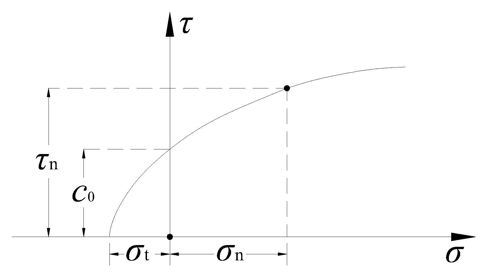
The Hoek–Brown failure criterion [26,27,28,29,30] was first put forward by Hoek and Brown in 1980. After 40 years of modification and improvement [30], the criterion has been widely used in the field of rock engineering. The criterion can effectively describe the nonlinear failure properties of the rock mass in low stress zone or tensile stress zone; especially for the jointed rock mass or fractured rock mass, it can be used to better estimate the strength of the rock mass. In the Mohr’ plane, the Hoek–Brown failure criterion can be expressed as [30,31]:
where A and B are dimensionless empirical parameters relating to rock mass properties, and the value range is (0, 1). and are the compressive strength and tensile strength of the rock mass, respectively.
Figure 1 shows the strength envelope curve of the Hoek–Brown failure criterion. When in Equation (1) and , , Hoek–Brown failure criterion can be reduced to the traditional Mohr–Coulomb failure criterion:
where and are the cohesion and internal friction angle of the rock mass, respectively.
3. Upper Bound Limit Analysis of Ultimate Pullout Capacity for a Single Pile
3.1. Failure Mechanism around an Uplift Pile
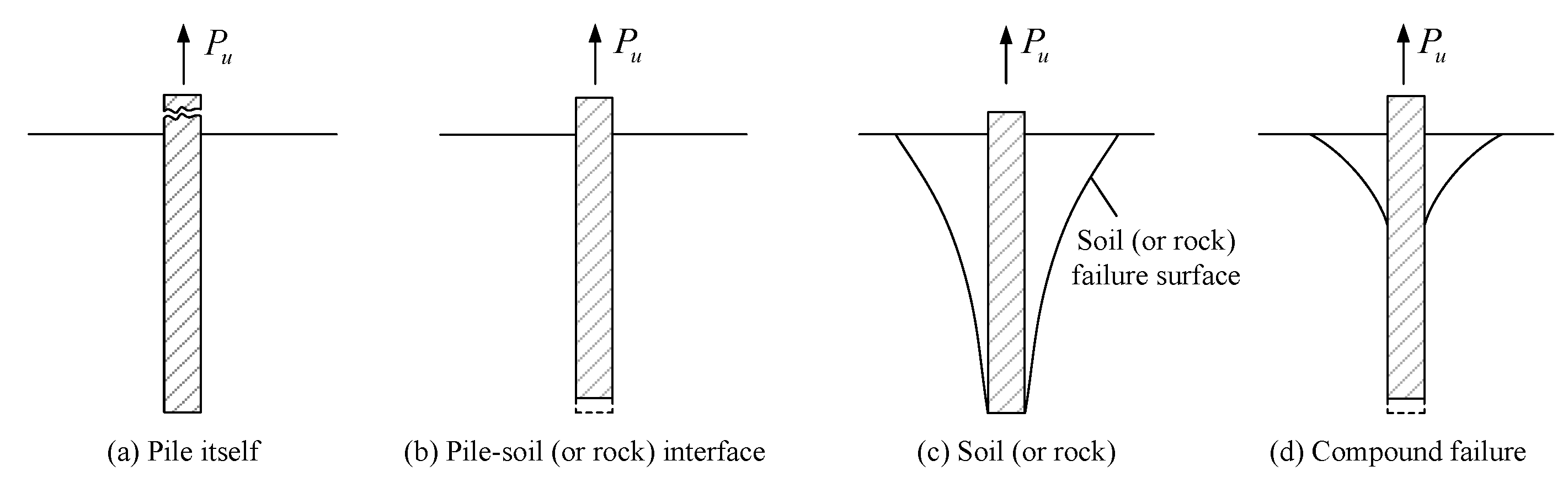
Figure 2 lists several common failure modes of pullout piles. The common failure modes of the uplift pile in practical engineering can be divided into four categories: broken pile body, slip failure along the pile–rock or pile–soil contact interface, integral trumpet-type failure of the rock or soil mass and composite failure around the pile.
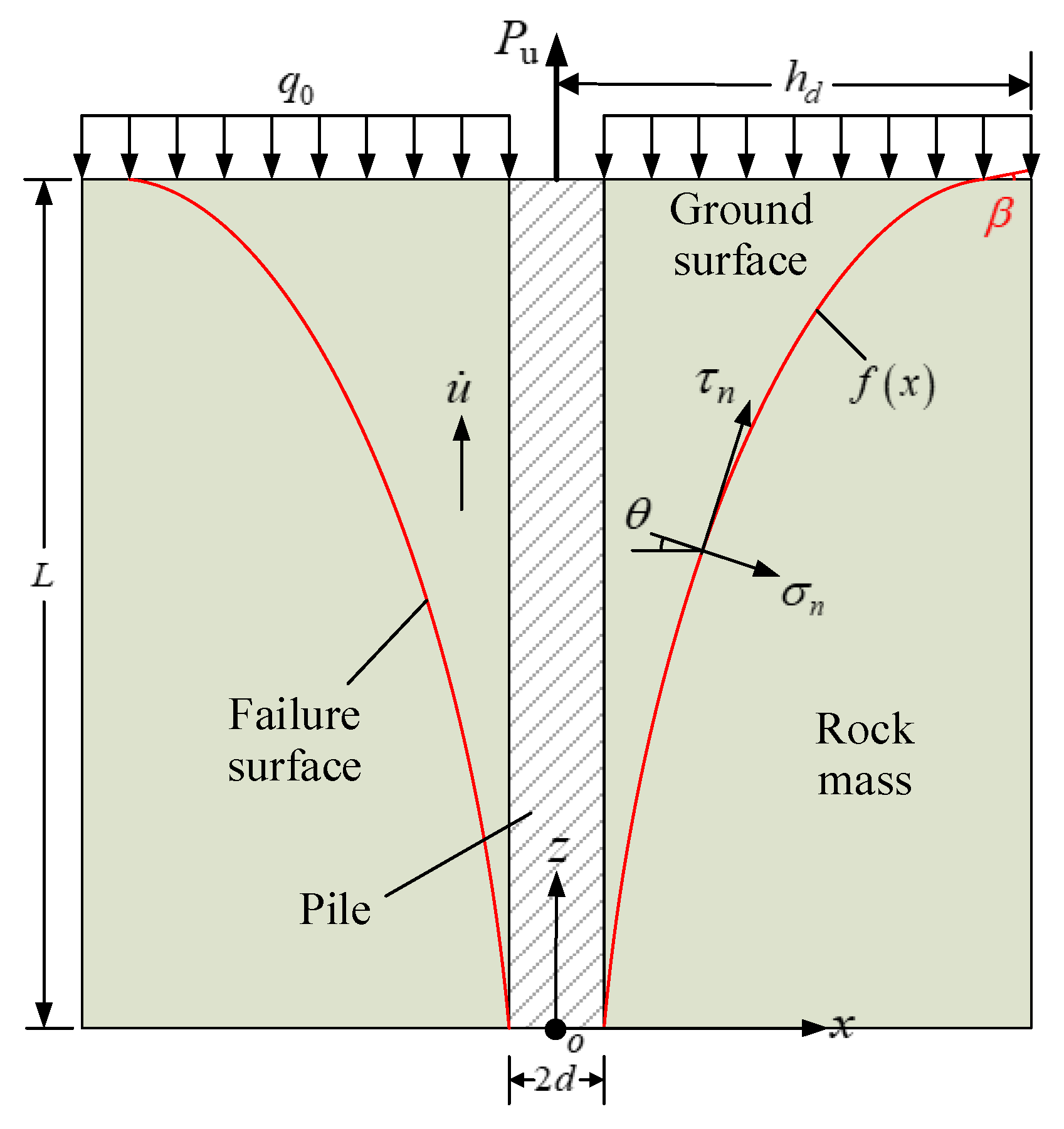
In this section, the failure of a single uplift pile in rock formation is selected for analysis. It should be noted that the overall strength of the rock mass is significantly higher than that of the soil mass. Particularly, when the cohesive strength of the pile–rock interface is greater than the strength of the rock mass, the rock mass around the uplift pile is more prone to monolithic failure. According to the existing test results, under vertical pullout load, the failure surface of the rock mass around the pile is an approximately inverted conical or trumpet-shaped. For example, Shanker et al. [2], Deshmukh et al. [3], He et al. [5] and Wang et al. [10] all adopted this failure form to study the pullout capacity of uplift piles. Based on this property of rock mass failure around the pile in these research works, a curve failure mechanism is further constructed, as shown in Figure 3.
In the failure mechanism shown in Figure 3, the pile length is L and the pile diameter is 2d. The additional load on the top surface of the pile is . The corresponding pullout capacity of the pile in the limit state is . The rock failure surface around the pile is assumed to be an unknown curved surface and in a three-dimensional axisymmetric failure mode. The corresponding rock failure range is axially symmetric with respect to the z-axis. The curve equation of the rock failure surface in the x–o–z plane is an unknown function , and the failure width at the top surface is . When is a straight line, the proposed failure model can be converted to the failure models proposed by Shanker et al. [2], Deshmukh et al. [3] and He et al. [5]. Meanwhile, it is assumed that the failure of the rock mass around the pile conforms to the Hoek–Brown failure criterion. Then, the shear stress and normal stress at any point of the rock failure surface are and , respectively, which satisfy Equation (1). Furthermore, according to the traditional plasticity theory, the rock mass around the pile is assumed to be an ideal rigid plastic material and homogeneous. Accordingly, the unstable rock mass around the pile and the pile body can be regarded as a combined rigid block, and failure only occurs at the rock failure surface. When the uplift load acts and reaches the ultimate failure state, it is considered that there is no relative sliding between the pile and the rock mass, and they both move upward with velocity in the positive direction along the z-axis. Then, a kinematically admissive velocity field corresponding to the pile failure is constructed, which can provide a theoretical basis for the following upper bound limit analysis.
3.2. Internal Energy Dissipation Rate
Since it is assumed that the rock mass around the pile satisfies the Hoek–Brown failure criterion, the corresponding yield function can be expressed as follows, according to Equation (1):
When the shear stress at the rock failure surface around the pile reaches the yield stress, the uplift pile will be damaged. According to the traditional theory of plastic mechanics, assuming that the plastic potential function surface and the Hoek–Brown yield function surface coincide in the stress space, an associated flow rule with the Hoek–Brown failure criterion can be established. Then, the traditional plastic potential theory [32] can be used:
where is the plastic potential function; is a plastic factor. Set and substitute Equation (3) with Equation (4), the results show that the plastic positive strain rate and the plastic shear strain rate at the failure surface should satisfy:
Meanwhile, according to the geometric relationship corresponding to the failure mechanism shown in Figure 3, the rock failure surface is regarded as a thin deformation layer with a certain thickness w. The corresponding plastic positive strain rate and plastic shear strain rate can also be expressed by the failure curve ; for the specific process, refer to references [31,32,33]. Then, the energy dissipation rate per unit volume at the failure surface can be expressed as:
Further, by integrating within the range in Figure 3, the total internal energy dissipation rate at the rock failure surface can be obtained:
where S is the total length of the curve within the range and satisfies .
3.3. Work Rates of External Forces
According to the failure mechanism in Figure 3, the work rates of external forces in the uplift failure process should include the work rate of the ultimate pullout capacity , the work rate of the additional surface load and the work rate of the rock weight around the pile, whereby the work rate of the ultimate pullout capacity is:
The work rate of the additional surface load is:
The work rate of the rock weight around the pile is:
3.4. Determination of Ultimate Pullout Capacity
According to the principle of virtual work rate, set the work rate of external forces to be equal to the internal energy dissipation rate:
By substituting Equations (7)–(10) into Equation (11), respectively, the ultimate pullout capacity of the pile can be obtained as:
where is:
According to the upper bound theorem, the ultimate pullout capacity determined by the above equation should be greater than the real solution. Moreover, the failure curve equation corresponding to Equation (12) is unknown. In combination with the failure mechanism shown in Figure 3, we should seek a minimum value of in all possible failure curves , which is closer to the real solution of . In other words, the optimal upper bound solution for should be its extreme value. Equation (12) is a functional of . This is a typical variational problem. According to the variational principle, using the Euler–Lagrange equation, the following equation can be obtained:
where
By substituting Equation (15) into Equation (14), the following equation can be obtained:
By integrating x on both sides of the above equation, the following equation can be obtained:
After rearrangement, the following equation can be obtained:
where is an undetermined constant, .
By integrating Equation (18), the curve equation for the rock failure surface around the uplift pile can be obtained. However, it is very difficult to solve this equation and find its analytical solution. Then, we cannot obtain an accurate expression for the ultimate pullout capacity of the uplift pile. This will provide great inconvenience to engineering application. If the failure of the rock mass around the pile is regarded as a plane problem in the x–o–z plane from a problem solving perspective, according to Figure 3, the upper bound method and the same thought as that for Equations (6)–(18) can also be used; then, it is easier to obtain :
where and are undetermined constants.
At this time, by using the geometric relationship in Figure 3, the unknown constants in the failure curve expression can be determined. Specifically, set the angle between the rock failure surface and the horizontal surface at the top of the pile to , then it can be known that:
Meanwhile, the following equations are satisfied within the range :
By substituting Equation (19) into Equations (20) and (21), constants and can be determined. Then, we may obtain the curve equation of the rock failure surface:
where the top failure width is:
Further, by substituting the curve equation of the rock failure surface into Equation (12), the ultimate pullout capacity of the uplift pile corresponding to monolithic failure of the rock mass can be obtained. However, it should be pointed out that, after being reduced, Equation (12) should only be a parameter equation about . In order to obtain the minimum upper bound solution, should also meet the following extremum conditions:
According to Equation (24), the value of the angle at the top of the failure surface can be determined; then, the rock failure surface and the ultimate pullout capacity of the pile can be determined. Since it is relatively complex to solve Equation (24), this study uses the Matlab R2018a software to solve it through programming.
4. Comparison with Numerical Simulation Results
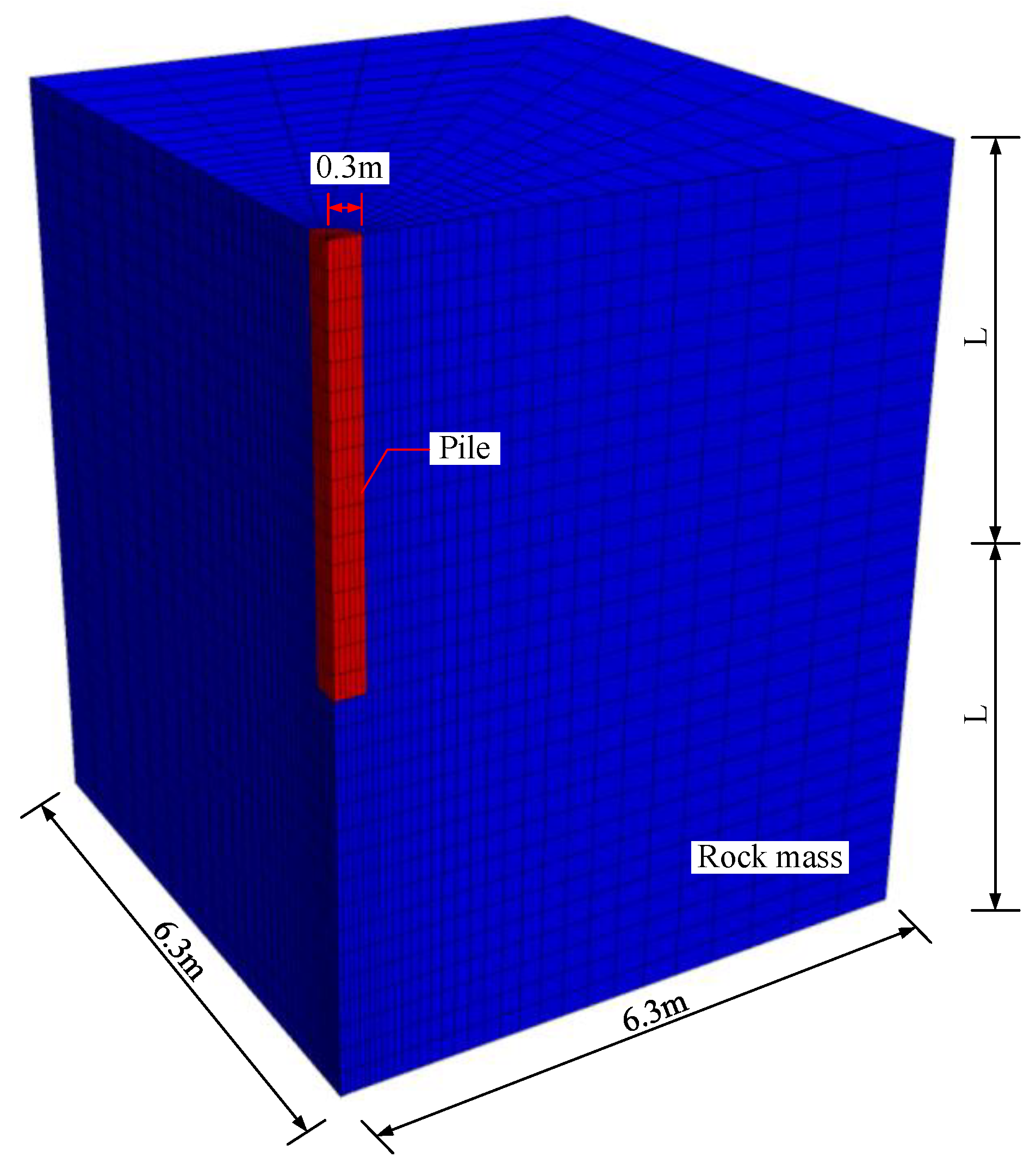
Based on the proposed method in this study, the pullout capacity of the uplift pile in rock formation can be estimated theoretically. In order to verify the effectiveness of the proposed method, FLAC-3D software is used to simulate the pullout failure process corresponding to different pile lengths. According to the axial symmetry characteristics, a numerical model was constructed in the range of a quarter around the pile, as shown in Figure 4. Taking the 6 m pile length model as an example, the pile diameter is 0.6 m, and the model size is 6.3 m × 6.3 m × 12 m. Gradient processing is carried out along the vertical and external piles during grid division. The numerical analysis model has a mesh number of 14,880 and a node number of 16,758. The rock mass density is 2000 kg/m3, and the pile density is 2500 kg/m3. In this model, in order to eliminate the boundary effect, according to references [34,35,36], the bottom boundary is fixed via vertical displacement, and the four lateral boundaries are fixed via horizontal displacement. The elastic model is used to simulate the pile, and the built-in Hoek–Brown constitutive model is used to simulate the rock mass around the pile. It should be noted that the Hoek–Brown model in the FLAC-3D software is defined by the expression in terms of the maximum and minimum principal stresses. But the proposed upper bound method in this study is on the basis of the Hoek–Brown expression in terms of the normal and shear stresses. The input parameters for the two forms of Hoek–Brown expressions are clearly different, which may cause difficulty for a comparison between these two methods. In order to overcome this problem, by referring the research work in ref. [37], a set of equivalent parameters in the calculation are employed, as listed in Table 1.
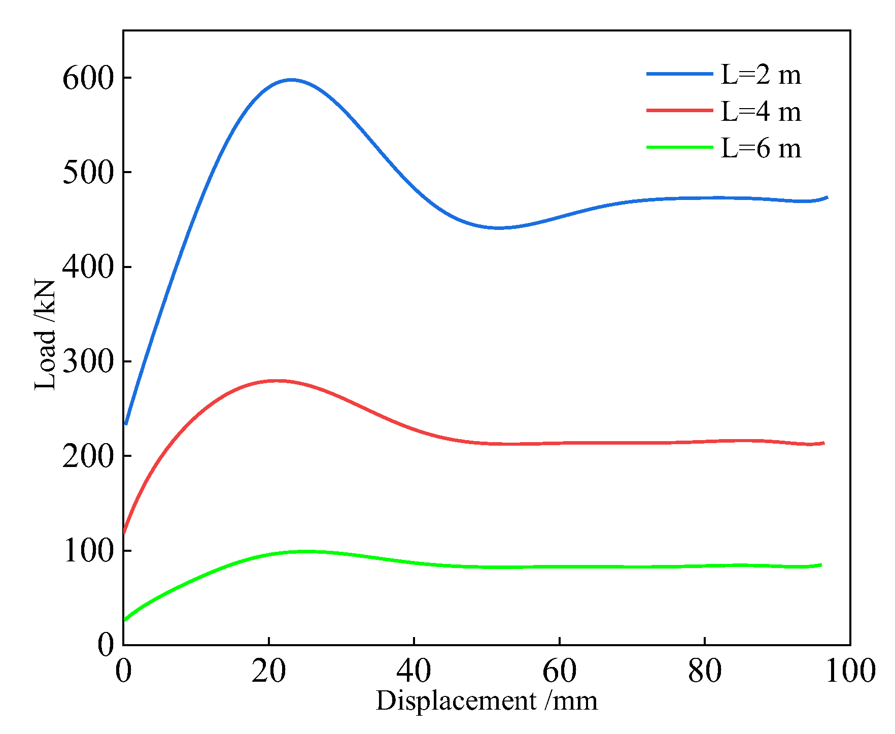
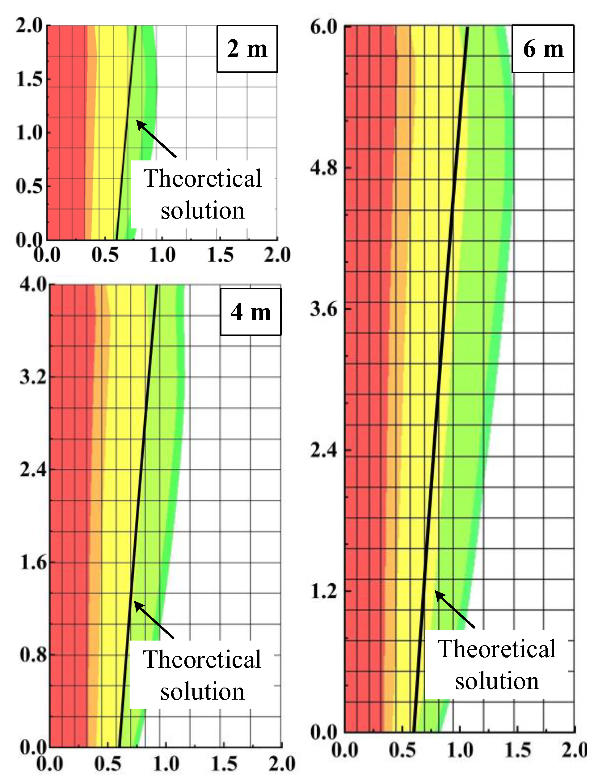
In the numerical simulation process, the initial ground stress is firstly calculated to achieve equilibrium within the model. Then, an upward velocity loading is applied on the top of the pile. Figure 5 lists the load–displacement curves corresponding to the pile length 2 m, 3 m and 4 m, respectively. Further, the peak loads are selected as the pile capacity, and Table 2 lists the comparison results between the numerical simulation method and the proposed upper bound method in this study. Figure 6 lists the vertical displacement contour of rock mass around the pile and the corresponding theoretical solution of rock failure surface. It can be seen from Table 2 and Figure 6 that the results obtained by the two methods are very close, with the largest difference being only 4.32%. At the same time, the failure surface of rock mass calculated in this study is in good agreement with the numerical simulation results, indicating that the proposed theoretical method has good effectiveness.
5. Results and Discussion
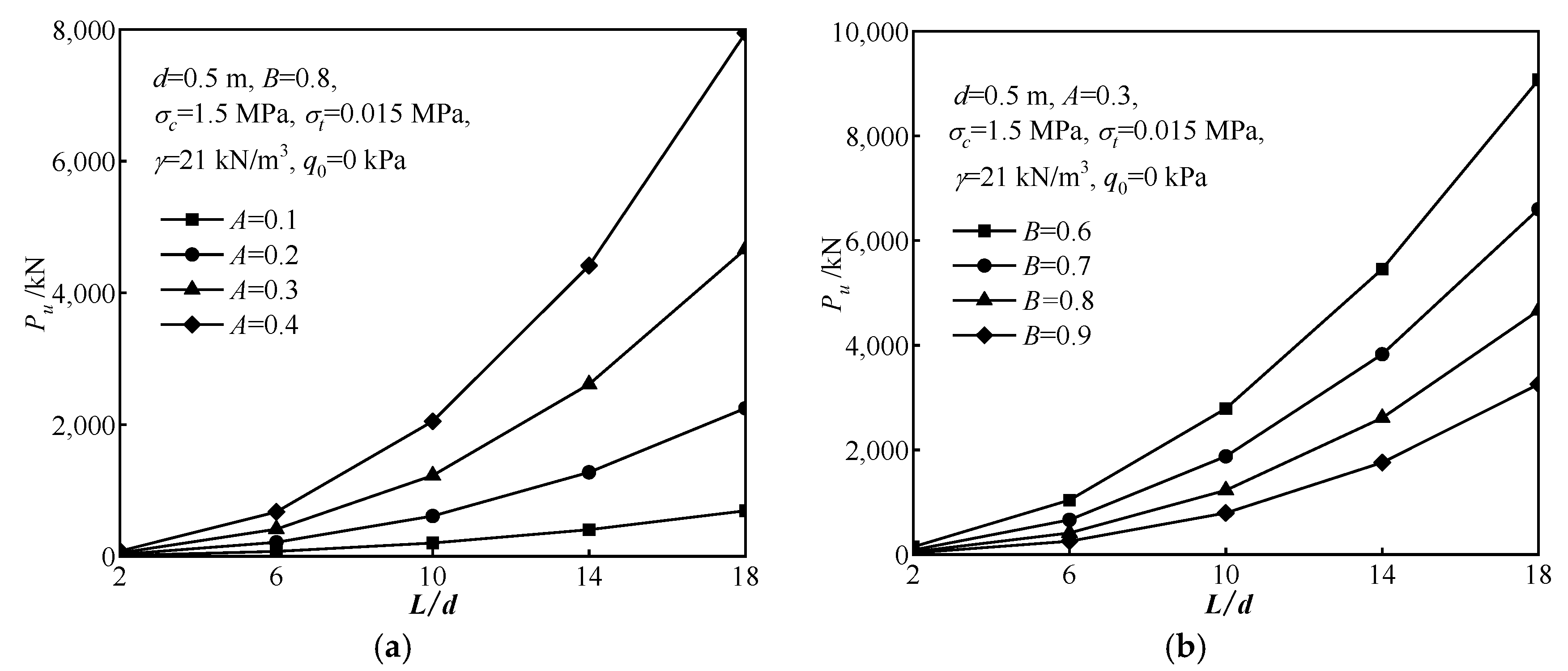
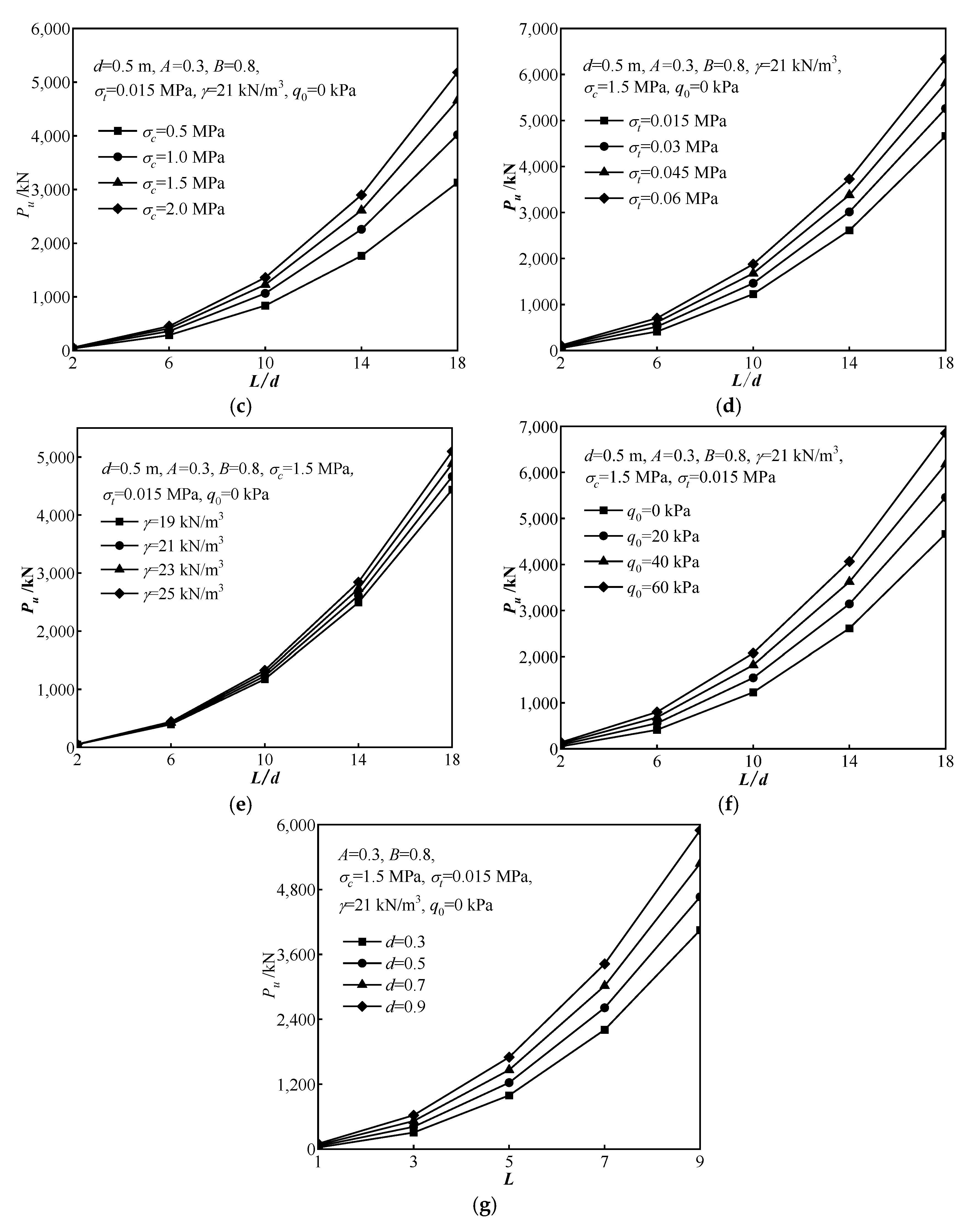
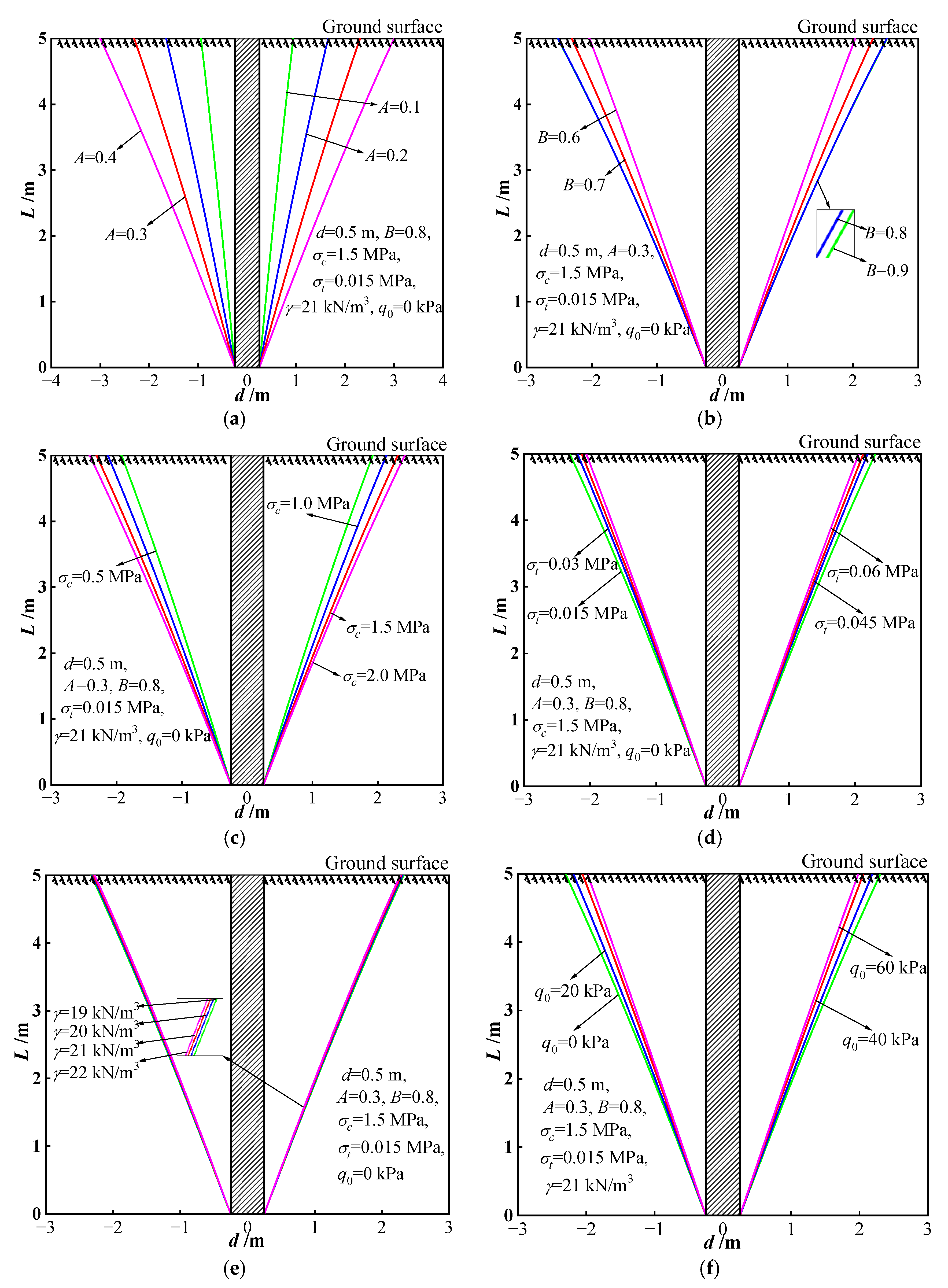
In order to further investigate the influence laws of different parameters on the pullout capacity, this section lists the variation curves of the ultimate pullout capacity corresponding to different rock parameters, pile length/diameter and additional surface loads, as shown in Figure 7. Further, taking the pile length of 5 m as an example, Figure 8 shows the shapes of rock failure surfaces under different parameters. Specifically, the adoptive parameters in theoretical calculation are listed in Table 3, and the other parameters are fixed when analyzing the change of one parameter.
5.1. Influence of Different Parameters on the Ultimate Pullout Capacity of the Pile
As can be seen from Figure 7a–f, the ultimate pullout capacity increases significantly with the increase in the length/diameter ratio , which is one of the most effective ways to improve the pullout capacity of piles in engineering practice. Meanwhile, rock empirical parameter A also has a significant influence on the pullout capacity of piles. As parameter A increases, the ultimate pullout capacity of the pile increases. When A is small, the increase in ultimate pullout capacity is slow; when A is large, the increase is more significant. As rock empirical parameter B increases, the ultimate pullout capacity of the pile decreases. In addition, when the rock compressive strength, tensile strength and unit weight increase, the quality of the rock mass increases, and the ultimate pullout capacity tends to increase. When the additional surface load increases, the resistance to be overcome when the uplift pile fails increases, and the corresponding pullout capacity also increases. It can also be seen from Figure 7g that the ultimate bearing capacity of the pile increases with the increase in the pile diameter when the pile length is determined. Moreover, it should be noted that when the pile length is larger, the influence of the above different mechanical parameters on the bearing capacity tends to be significant.
5.2. Influence of Different Parameters on the Failure Range of the Rock Mass around the Pile
As can be seen from Figure 8a–f, the rock failure surface around the pile presents a symmetrical “trumpet shape” under different parameters. When the length/diameter ratio is constant, the rock failure range around the pile increases with the increase in rock empirical parameter A and compressive strength, but decreases with the increase in rock empirical parameter B, tensile strength, unit weight and additional surface load. Compared with the rock tensile strength, compressive strength, unit weight and additional surface load, rock empirical parameters A and B have a more significant influence on the shape of the rock failure range, where rock empirical parameter B determines the curvature of the failure surface. As parameter B increases, the curvature of the failure surface decreases. When B = 1, the nonlinear Hoek–Brown criterion degrades to the linear Mohr–Coulomb criterion, and then the corresponding rock failure surface can be degraded to a circular conical surface.
5.3. Recommendations for Engineering Application
According to the above influence laws of different parameters on the capacity and failure range of the uplift pile, this study provides the following recommendations for better guidance in engineering design and construction:
- (1)
- Increasing the pile length is an effective way to enhance the ultimate pullout capacity. But it should be noted that, when increasing the pile length, the diameter and tension strength of the pile body should also be increased in order to enhance the safety and avoid fracture at the pile body.
- (2)
- The pile capacity is significantly affected by the rock strength, and the disturbance on the rock masses around the pile should be reduced as much as possible in drilling and construction processes. In hard rock ground, due to the high strength of the rock masses, the corresponding pile length can be reduced properly, whereas in soft rock ground, the grouting reinforcement technique can be utilized to improve the rock quality and enhance the ultimate pullout capacity of the pile.
- (3)
- When the pile length and rock strength parameters are determined, setting additional loading on the top surface of the pile is also an effective way to enhance the pullout capacity and long-term stability of the pile foundation.
6. Conclusions
- (1)
- Focusing on the piles in rock ground, this study constructed a curved uplift failure mechanism corresponding to the monolithic failure of the rock mass around a single pile. Based on the proposed mechanism and the Hoek–Brown failure criterion, the upper bound limit analysis of the pile failure was conducted. The theoretical prediction formulas for the rock failure surface and the ultimate pullout capacity of the pile were derived, and can provide some theoretical reference for the practical design of uplift piles.
- (2)
- The numerical simulation of the pullout failure processes corresponding to different pile lengths was conducted for comparison with the proposed theoretical method. The results obtained from the two methods are very close, and the maximum difference is only 4.32%, which further verifies the effectiveness of the proposed method in this study.
- (3)
- The influence laws of rock parameters, pile design parameters and additional surface load on the pile capacity and failure range were obtained. Specifically, the ultimate pullout capacity of the pile is positively correlated with the length/diameter ratio, rock empirical parameter A, tensile strength, compressive strength, unit weight and additional surface load, but negatively correlated with rock empirical parameter B. Empirical parameters A and B are key factors affecting the pile capacity and rock failure range, and should be attached importance to in engineering design.
Author Contributions
Conceptualization, C.L. and H.W.; Data curation, C.L., F.J. and Y.S.; Formal analysis, J.L., Z.X. and M.Z.; Funding acquisition, H.W.; Investigation, F.J., Y.S., J.L. and Z.X.; Project administration, C.L.; Resources, C.L., F.J. and H.W.; Software, J.L., Z.X. and M.Z.; Writing—original draft, M.Z.; Writing—review, F.J. and Y.S. All authors have read and agreed to the published version of the manuscript.
Funding
Much of the work presented in this paper was supported by the National Natural Science Foundation of China (No. 52374093), Project funded by China Postdoctoral Science Foundation (No. 2022M711314), Shandong Provincial Natural Science Foundation (No. ZR2022ME088).
Data Availability Statement
The data used to support the findings of this study are included within the article.
Conflicts of Interest
Authors Chi Liu, Fang Ji, Yang Song, Hongtao Wang were employed by the company Jinan Rail Transit Group Co., Ltd. The remaining authors declare that the research was conducted in the absence of any commercial or financial relationships that could be construed as a potential conflict of interest.
Notation
The following symbols are used in this study:
| A | empirical parameter (non-dimensional parameter) |
| B | empirical parameter (non-dimensional parameter) |
| compressive strength of the rock mass | |
| tensile strength of the rock mass | |
| cohesion of the rock mass | |
| internal friction angle of the rock mass | |
| additional load on the top surface of the pile | |
| pullout capacity of the pile in the limit state | |
| curve equation of the rock failure surface in the plane x–o–z | |
| failure width at the top surface | |
| shear stress at the failure surface | |
| normal stress at the failure surface | |
| F | yield function |
| Q | plastic potential function |
| plastic factor | |
| w | thickness of the thin deformation layer |
| plastic positive strain rate | |
| plastic shear strain rate | |
| energy dissipation rate per unit volume | |
| S | total length of the failure curve |
| work rate of the ultimate pullout capacity | |
| work rate of the rock weight around the pile | |
| internal energy dissipation rate | |
| d | pile diameter |
| unit weight of the rock mass | |
| additional surface load | |
| a | pile diameter |
| empirical parameter | |
| geological strength index |
References
- Khatri, V.N.; Kumar, J. Uplift capacity of axially loaded piles in clays. Int. J. Geomech. 2011, 11, 23–28. [Google Scholar] [CrossRef]
- Shanker, K.; Basudhar, P.K.; Patra, N.R. Uplift capacity of single piles: Predictions and performance. Geotech. Geol. Eng. 2007, 25, 151–161. [Google Scholar] [CrossRef]
- Deshmukh, V.B.; Dewaikar, D.M.; Choudhury, D. Computations of uplift capacity of pile anchors in cohesionless soil. Acta Geotech. 2010, 5, 87–94. [Google Scholar] [CrossRef]
- Zhu, B.T.; Yang, M. Calculation of displacement and ultimate uplift capacity of tension piles. J. Build. Struct. 2006, 27, 120–129. (In Chinese) [Google Scholar]
- He, S.M.; Zhang, X.X.; Wang, D.P. Study of computation methods of ultimate uplift capacity and determining position of failure surface of uplift piles in layered soil. Rock Soil Mech. 2012, 33, 1433–1437. (In Chinese) [Google Scholar]
- Su, Q.; Zhang, X.; Yin, P.; Zhao, W. Ultimate capacity analysis and determination of the position of failure surface for uplift piles. Math. Probl. Eng. 2014, 2014, 540143. [Google Scholar] [CrossRef]
- Cheng, S.; Zhang, Q.Q.; Li, S.C.; Li, L.P.; Zhang, S.M.; Wang, K. Nonlinear analysis of the response of a single pile subjected to tension load using a hyperbolic model. Eur. J. Environ. Civ. Eng. 2018, 22, 181–191. [Google Scholar] [CrossRef]
- Li, J.J.; Huang, M.S.; Mu, L.L.; Wang, W.D.; Chen, Z. Research on computation methods of uplift capacity of enlarged base pile in layered soils. Rock Soil Mech. 2008, 29, 1997–2003. (In Chinese) [Google Scholar]
- Yang, X.L.; Zou, J.F. Displacement and deformation analysis for uplift piles. J. Cent. South Univ. Technol. 2008, 15, 906–910. [Google Scholar] [CrossRef]
- Wang, H.T.; Yin, Y.T.; Ma, F.; Liu, P. Simplified Analytical Method for Calculating the Uplift Capacity of a Single Pile in Nonhomogeneous Soil with a Nonlinear Failure Criterion. Geotech. Geol. Eng. 2019, 37, 4627–4633. [Google Scholar] [CrossRef]
- Shelke, A.; Mishra, S. Uplift capacity of single bent pile and pile group considering arching effects in sand. Geotech. Geol. Eng. 2010, 28, 337–347. [Google Scholar] [CrossRef]
- Zhang, Q.Q.; Li, S.C.; Zhang, Q.; Li, L.P.; Zhang, B. Analysis on response of a single pile subjected to tension load using a softening model and a hyperbolic model. Mar. Georesources Geotechnol. 2015, 33, 167–176. [Google Scholar] [CrossRef]
- Xu, F.; Zhang, Q.Q.; Li, L.P.; Wang, K.; Zhang, S.M.; He, P. Response of a single pile subjected to tension load by using softening models. Soil Mech. Found. Eng. 2017, 54, 24–31. [Google Scholar] [CrossRef]
- Alawneh, A.S.; Malkawi AI, H.; Al-Deeky, H. Tension tests on smooth and rough model piles in dry sand. Can. Geotech. J. 1999, 36, 746–753. [Google Scholar] [CrossRef]
- Dash, B.K.; Pise, P.J. Effect of compressive load on uplift capacity of model piles. J. Geotech. Geoenvironmental. Eng. 2003, 129, 987–992. [Google Scholar] [CrossRef]
- He, H.N.; Dai, G.L.; Gong, W.M. Review of Computational Models and Methods for Predicting Ultimate Capacity of Uplift Piles with Uniform Cross Section. J. Highw. Transp. Res. Dev. 2015, 9, 69–76. [Google Scholar] [CrossRef]
- Mahmood, M.R.; Kadhim, S.T.; Sarhan, W.K. Evaluation of pull-out capacities of different pile models embedded in unsaturated sandy soil. IOP Conf. Ser. Mater. Sci. Eng. 2020, 737, 012117. [Google Scholar] [CrossRef]
- Abd-Awn, S.H.; Hussein, H.Q. Pullout capacity of single pile in gypseous soil. In Proceedings of the 2018 1st International Scientific Conference of Engineering Sciences—3rd Scientific Conference of Engineering Science (ISCES), Diyala, Iraq, 10–11 January 2018; pp. 249–253. [Google Scholar]
- Nazir, A.; Nasr, A. Pullout capacity of batter pile in sand. J. Adv. Res. 2013, 4, 147–154. [Google Scholar] [CrossRef]
- Huang, M.S.; Ren, Q.; Wang, W.D.; Chen, Z. Analysis for ultimate uplift capacity of tension piles under deep excavation. Chin. J. Geotech. Eng. 2008, 29, 1689–1695. (In Chinese) [Google Scholar]
- Mu, Y.; Pu, S.Y.; Huang, Z.H.; Li, Y.H.; Zheng, P.X.; Liu, Y.; Liu, Z.; Zheng, H.C. Determination of ultimate bearing capacity of uplift piles in combined soil and rock masses. Rock Soil Mech. 2019, 40, 2825–2837. (In Chinese) [Google Scholar]
- Basack, S.; Nimbalkar, S. Numerical solution of single pile subjected to torsional cyclic load. Int. J. Geomech. 2017, 17, 04017016. [Google Scholar] [CrossRef]
- Nimbalkar, S.; Basack, S. Pile group in clay under cyclic lateral loading with emphasis on bending moment: Numerical modelling. Mar. Georesources Geotechnol. 2022, 41, 269–284. [Google Scholar] [CrossRef]
- Johari, A.; Talebi, A. Stochastic analysis of piled-raft foundations using the random finite-element method. Int. J. Geomech. 2021, 21, 04021020. [Google Scholar] [CrossRef]
- Johari, A.; Hajivand, A.K.; Binesh, S.M. System reliability analysis of soil nail wall using random finite element method. Bull. Eng. Geol. Environ. 2020, 79, 2777–2798. [Google Scholar] [CrossRef]
- Brown, E.T. Underground Excavations in Rock; CRC Press: Boca Raton, FL, USA, 1980. [Google Scholar]
- Hoek, E.; Brown, E.T. Empirical strength criterion for rock masses. J. Geotech. Eng. Div. 1980, 106, 1013–1035. [Google Scholar] [CrossRef]
- Hoek, E.; Carranza-Torres, C.; Corkum, B. Hoek-Brown failure criterion-2002 edition. In Proceedings of the NARMS-Tac, Toronto, ON, Canada, 7–10 July 2002; Volume 1, pp. 267–273. [Google Scholar]
- Hoek, E.; Marinos, P. A brief history of the development of the Hoek-Brown failure criterion. Soils Rocks 2007, 2, 2–13. [Google Scholar] [CrossRef]
- Hoek, E.; Brown, E.T. The Hoek-Brown failure criterion and GSI-2018 edition. J. Rock Mech. Geotech. Eng. 2019, 11, 445–463. [Google Scholar] [CrossRef]
- Fraldi, M.; Guarracino, F. Limit analysis of collapse mechanisms in cavities and tunnels according to the Hoek-Brown failure criterion. Int. J. Rock Mech. Min. Sci. 2009, 46, 665–673. [Google Scholar] [CrossRef]
- Wang, H.; Liu, L.; Li, S.; Wang, Q.; Li, W.; Meng, Q. An upper bound design method for roof bolting support in roadways with top coal. Arab. J. Geosci. 2021, 14, 790. [Google Scholar] [CrossRef]
- Chen, W.F. Limit Analysis and Soil Plasticity; Elsevier: Amsterdam, The Netherlands, 2013. [Google Scholar]
- Tanoli, A.Y.; Yan., B.; Xiong, Y.; Ye, G.L.; Khalid, U.; Xu, Z.H. Numerical analysis on zone-divided deep excavation in soft clays using a new small strain elasto–plastic constitutive model. Undergr. Space 2022, 7, 19–36. [Google Scholar] [CrossRef]
- Yadav, S.K.; Ye, G.; Xiong, Y.; Khalid, U. Unified numerical study of shallow foundation on structured soft clay under unconsolidated and consolidated-undrained loadings. Mar. Georesources Geotechnol. 2020, 38, 400–416. [Google Scholar] [CrossRef]
- Yadav, S.K.; Ye, G.; Khalid, U.; Fukuda, M. Numerical and centrifugal physical modelling on soft clay improved with floating and fixed sand compaction piles. Comput. Geotech. 2019, 115, 103160. [Google Scholar] [CrossRef]
- Wang, H.T.; Liu, L.Y.; Zhang, J.G.; Li, X.J.; Li, J.J. Prediction of anchor cable supporting force for roadways with top coal based on Hoek-Brown strength parameters and its application. J. China Univ. Min. Technol. 2022, 51, 244–256. [Google Scholar]
Figure 1.
Hoek–Brown failure criterion.

Figure 2.
Typical failure modes of uplift pile.

Figure 3.
Failure mechanism for an uplift pile.

Figure 4.
Numerical model for the pullout failure simulation of piles.

Figure 5.
Load–displacement curves of piles in pullout process.

Figure 6.
Vertical displacement cloud map and theoretical solution of failure surface.

Figure 7.
Ultimate pullout capacity of uplift piles under different mechanical parameters. (a) empirical parameter A. (b) empirical parameter B. (c) compressive strength. (d) tensile strength. (e) unit weight. (f) additional surface load. (g) pile diameter.
Figure 7.
Ultimate pullout capacity of uplift piles under different mechanical parameters. (a) empirical parameter A. (b) empirical parameter B. (c) compressive strength. (d) tensile strength. (e) unit weight. (f) additional surface load. (g) pile diameter.


Figure 8.
Rock failure surfaces around the uplift pile under different parameters. (a) empirical parameter A. (b) empirical parameter B. (c) compressive strength. (d) tensile strength. (e) unit weight. (f) additional surface load.
Figure 8.
Rock failure surfaces around the uplift pile under different parameters. (a) empirical parameter A. (b) empirical parameter B. (c) compressive strength. (d) tensile strength. (e) unit weight. (f) additional surface load.


Table 1.
Equivalent parameters employed in numerical simulation.
| Hoek–Brown Parameters in the Proposed Upper Bound Method | Equivalent Hoek–Brown Parameters in Numerical Simulation |
|---|---|
| A = 0.0796 B = 0.5 σc = 1.0 MPa σt = 0.03 MPa γ = 20 kN/m3 | a = 0.5 mb = 0.0289 s = 0 σc = 1.0 MPa GSI = 35 γ = 20 kN/m3 |
Table 2.
Comparison of pile capacity between numerical simulation results and upper bound solutions.
Table 2.
Comparison of pile capacity between numerical simulation results and upper bound solutions.
| Pile Length | Numerical Simulation Results | Upper Bound Solutions in This Study | Maximum Difference |
|---|---|---|---|
| 2 m | 101.42 kN | 97.66 kN | 3.85% |
| 4 m | 280.25 kN | 271.41 kN | 3.26% |
| 6 m | 534.41 kN | 512.29 kN | 4.32% |
Table 3.
Adoptive parameters in theoretical calculation.
| Parameter | Value Range |
|---|---|
| Pile diameter | 0.3–0.9 m |
| Length | 1–9 m |
| Empirical parameter | 0.1–0.4 |
| Empirical parameter | 0.6–0.9 |
| Compressive strength | 0.5–2.0 MPa |
| Tensile strength | 0.015–0.06 MPa |
| Unit weight | 19–25 kN/m3 |
| Additional surface load | 0–60 kPa |
Disclaimer/Publisher’s Note: The statements, opinions and data contained in all publications are solely those of the individual author(s) and contributor(s) and not of MDPI and/or the editor(s). MDPI and/or the editor(s) disclaim responsibility for any injury to people or property resulting from any ideas, methods, instructions or products referred to in the content. |
© 2023 by the authors. Licensee MDPI, Basel, Switzerland. This article is an open access article distributed under the terms and conditions of the Creative Commons Attribution (CC BY) license (https://creativecommons.org/licenses/by/4.0/).
Share and Cite
MDPI and ACS Style
Liu, C.; Ji, F.; Song, Y.; Wang, H.; Li, J.; Xuan, Z.; Zhao, M. Upper Bound Analysis of Ultimate Pullout Capacity for a Single Pile Using Hoek–Brown Failure Criterion. Buildings 2023, 13, 2904. https://doi.org/10.3390/buildings13122904
AMA Style
Liu C, Ji F, Song Y, Wang H, Li J, Xuan Z, Zhao M. Upper Bound Analysis of Ultimate Pullout Capacity for a Single Pile Using Hoek–Brown Failure Criterion. Buildings. 2023; 13(12):2904. https://doi.org/10.3390/buildings13122904
Chicago/Turabian StyleLiu, Chi, Fang Ji, Yang Song, Hongtao Wang, Jianhua Li, Zhaoteng Xuan, and Mingzhu Zhao. 2023. "Upper Bound Analysis of Ultimate Pullout Capacity for a Single Pile Using Hoek–Brown Failure Criterion" Buildings 13, no. 12: 2904. https://doi.org/10.3390/buildings13122904
Note that from the first issue of 2016, this journal uses article numbers instead of page numbers. See further details here.