
Economical Design Comparison of Large-Span Composite Floor Systems with I Beams and Corrugated Web Beams

1
College of Civil Engineering and Architecture, Zhejiang University, Hangzhou 310058, China
2
Center for Balance Architecture, Zhejiang University, Hangzhou 310028, China
3
Architectural Design and Research Institute of Zhejiang University Co., Ltd., Hangzhou 310028, China
4
Key Laboratory of Space Structures of Zhejiang Province, Hangzhou 310058, China
5
Future City Laboratory, Innovation Center of Yangtze River Delta, Zhejiang University, Jiaxing 314100, China
*
Author to whom correspondence should be addressed.
Buildings 2023, 13(8), 1940; https://doi.org/10.3390/buildings13081940
Submission received: 27 June 2023
/
Revised: 28 July 2023
/
Accepted: 29 July 2023
/
Published: 30 July 2023
(This article belongs to the Special Issue High-Performance Steel–Concrete Composite/Hybrid Structures)
Abstract
:A comparative study of composite floor systems with I-beams and corrugated web beams is performed based on non-linear programming (NLP) algorithm. The optimization is conducted to find the most economical design with minimum steel consumption considering variables associated with the cross-sectional dimensions and multiple constraints from standards, specifications and engineering practices. Various parameters of live loads ranging from 2 to 10 kN/m2 and spans ranging from 20 to 100 m are considered. The optimization results reveal that composite floors with corrugated web beams have reasonable and economical cross-sections with less steel consumption, owing to the high performance of the corrugated web in shear resistance and stability. Further comparative studies show that composite floors with corrugated web beams are economically competitive for spans larger than 30 m with a steel saving of 20–60%, and composite floors with welded I-beams can be applicable for spans less than 30 m considering the simpler configuration and construction. In addition, a spatially structured cable-supported steel–concrete composite floor system is proposed and recommended for super-large-span floor structures considering the cost-effectiveness of the analyzed floor systems reduces as the span further increases.
1. Introduction
The functions of buildings have seen diverse development with the prosperity of economy and social culture. Traditional large-span structures mainly include roof systems made of light-weight steel, which basically have one floor of large space [1]. In recent decades, an increasing number of large-space buildings with multistorey floors have been designed for construction projects like industrial plants, transportation centers and sports stadiums, in which the steel–concrete composite floor systems are widely applied [2,3,4,5]. Hence, considering these increasing demands, it is of great significance to study the optimization of large-span steel–concrete floor systems to better satisfy the requirements of multistorey spatial buildings.
For the optimization of steel–concrete composite floor systems, different optimization techniques have been introduced in terms of the different study intentions. A segment of research studies has investigated the optimization of steel–concrete composite floors through meta-heuristic algorithms based on some small-scale design cases with defined spans and live loads [6,7,8,9,10]. Kaveh and Ahangaran [6] conducted the cost optimization of composite floors with design parameters of spans ranging from 5 to 8 m and live loads from 2 to 4 kN/m2 based on the Social Harmony Search (SHS) model. Poitras et al. [7] investigated the steel consumption of composite floors with spans of 10 and 12 m based on Particle Swarm Optimization (PSO). Kaveh and Massoudi [8], Senouci and Al-Ansari [9] and Korouzhdeh et al. [10] studied the cost differences between composite floors with 4–10 m spans under certain live loads based on Ant Colony Optimization (ACO), Genetic Algorithm (GA) and Improved Ant Colony Optimization (IACO), respectively. In these studies, the steel beams examined were standard rolled sections and thus the variables were considered as discrete variables. Furthermore, the efficiencies of the studied algorithms for structural optimization were largely described by showing the optimization results of the selected cases regarding the defined design conditions.
Some researchers expanded the design scale of the composite floor with varying parameters of spans and live loads to discuss the applicable working conditions and economic competitiveness of long span steel–concrete composite floor systems, in which the variables are basically treated as continuous variables and thus the non-linear programming techniques were basically utilized. Kravanja and Šilih [11] introduced a two-step optimization method based on NLP and MILP and compared the economic advantages of using composite floors with welded I-beams and steel trusses within spans of 50 m. The results showed that composite floors with welded I-beams could meet the economical design requirements for spans up to 50 m and their section heights were significantly smaller than those of composite floors with steel trusses. Kavanja et al. [12] performed a comparison between composite floors with welded and standard steel I-beams for spans up to 50 m and live loads up to 10 kN/m2 based on NLP approach. Their investigation showed that the economical competitive span for composite floors with standard I-beams was 15–20 m, and composite floors with welded I-beams were economical and suitable for spans up to 50 m.
For super-large-span or super-heavy-load situations where traditional steel–concrete composite floor systems with I-beams are not economically suited, composite floor systems with corrugated web composite beams may be used. The corrugated web composite beam has been widely employed in bridge engineering due to its proven high load-bearing efficiency and exceptional shear resistance [13,14,15,16,17,18]. Hence, it is a productive way to apply the corrugated web steel beam in floor structures to enhance the spanning capability of composite floor systems. Erdal et al. [19] investigated the optimal design of a corrugated web composite beam with 5-m span based on hunting search algorithm. The results showed that material savings could be realized without weakening the ultimate load-carrying capability of corrugated web composite beams by using a greater part of the material for the flanges and thinner web. Leblouba et al. [20] validated through experiments that the shear strength of corrugated webs was approximately 1.6 times that of the straight web with similar dimensions. They also conducted the optimization on a 36.6-m span composite bridge girder with corrugated steel webs, and found that the corrugation resulted in 40% saving in steel volume of the web compared to the flat web design.
Existing studies on the optimal design of composite beams/floors with corrugated webs provide optimized cases (with defined design parameters) regarding the material saving achieved from the improved configuration of the steel web. However, the overall cost-effectiveness of composite beams/floors with corrugated webs is still undescribed. It is of significance to study the cost-effectiveness of the composite floor system with corrugated web beams with various design parameters and to compare the scope of suitable application of this system with the traditional composite floor system. Since the performance of composite floors with I-beams has been demonstrated with spans up to 50 m, this paper investigates the optimal design comparison for composite floor systems with welded I-beams and corrugated web beams with an extended span limit of 100 m based on NLP algorithm. The optimal problem is built on simply supported composite floors with welded I-beams and corrugated web beams with various input parameters of spans and live loads. Under different combinations of spans and loads, the cost-effectiveness of composite floors is evaluated according to an objective function that considers the consumption of materials for steel and concrete. The variables of the composite floors with welded I-beams and corrugated web beams are defined as major design parameters, including the thickness of the concrete slab, the intermediate space of the steel beams and the cross-sectional dimensions of the steel beams. The optimization is executed with constraints in accordance with Chinese codes and specifications for design and requirements from engineering practices. Considering that the flexural resistance contributed by the top flange is limited, a mono-symmetrical steel section is adopted in the optimal design to maximize material saving. The concrete and steel grade determined in the design of composite floors are derived from the typical engineering options in order to fit the engineering practices. It should be noted that the optimal problem is developed from the perspective of economical design, while the construction, maintenance and labor costs are not involved in the discussion of cost-effectiveness.
For the purpose of investigating the economical difference and large-span applicability of composite floors with welded I-beams and corrugated web beams, this paper proposes an optimization-based comparison based on an extended parameter range of spans varying from 20 to 100 m and live loads varying from 2 to 10 kN/m2. The configuration of the steel member for the discussed composite floors specifically adopts a welded mono-symmetrical section with flat web or sinusoidally corrugated web. Correspondingly, the studied cross-sectional dimensions are defined as consecutive variables to suit the design practices for welded sections. The different locations of the plastic neutral axis and complicated constraints related to design are also fully considered in the optimization. By processing and analyzing the optimization results, the significant achievements include:
- The optimal cross-sectional properties of the steel beam shape, distribution of the steel beams and the location of the plastic neutral axis for the studied composite floor systems.
- The advantage brought about by the web corrugation and its impact on material consumption for composite floors with corrugated web beams.
- The differences in cost-effectiveness and the applicable scopes of the studied composite floor systems, as well as their adaptabilities under design conditions of large spans and heavy loads.
Finally, the underlying cause of the economical difference between the studied composite floor systems is analyzed, leading to a design concept for composite floor structures in super-large spans. Based on the design concept, a new form of spatially structured cable-supported steel–concrete composite floor system is proposed and recommended for super-large span structures, in which the spanning capabilities of conventional composite floors are compromised.
2. Problem Definition
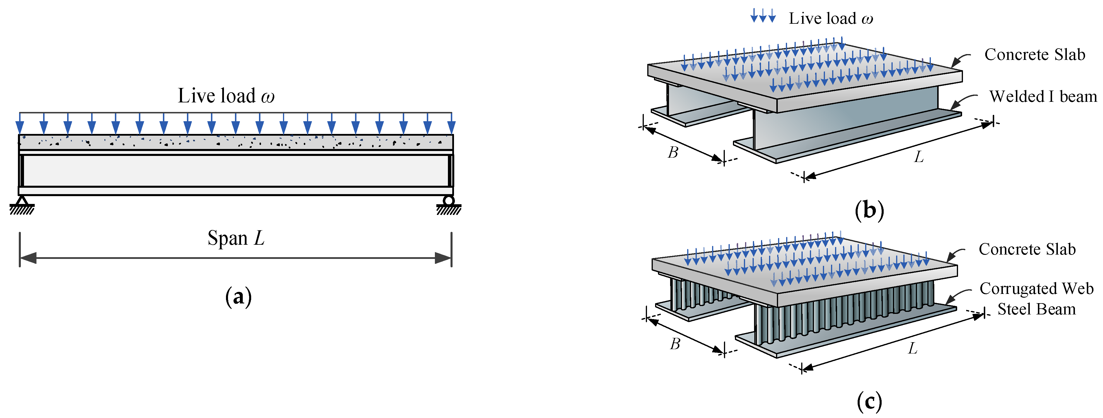
Consider the design of a simply supported steel–concrete composite floor system (Figure 1) with two input parameters: live load ω (ranging from 2 to 10 kN/m2) and span length L (ranging from 20 to 100 m). Two types of designs are considered: steel–concrete composite floors with welded I-sectional steel beams (Case I), and composite floors with corrugated web steel beams (Case II), as shown in Figure 1b and Figure 1c, respectively.
In both cases, the material properties and the reinforcement are set as follows:
(1) C35 concrete widely used in construction is considered, which has a design compressive strength (fc) of 16.7 MPa. Steel beams are made from Q355b steel with a yield strength (fy) of 355 MPa, design strength (f) of 305 MPa and design shear strength (fv) of 205 MPa. The concrete density (γc) is considered as 2500 kg/m3, and steel density (γs) as 7850 kg/m3.
(2) The steel consumption from the reinforcement of concrete slab is also taken into consideration. A dual-layer two-way reinforcement is applied, where the main reinforcement ratio at the bottom of the slab is the economic reinforcement ratio of 0.6%, while the distribution reinforcement ratio at the bottom and the two-way reinforcement ratio at the top of the slab are 0.2% according to the structural requirements [21].
The problem at hand is to seek the optimal design (i.e., most economical design) of the composite floor system under the two cases. The objective function used to evaluate the cost-effectiveness of different designs is defined as
where W is the general steel consumption per square meter (kg/m2) which considers the concrete cost by replacing it with equivalent cost of steel. As is the cross-sectional area of the steel beam, Ac is the area of the concrete slab, B is the intermediate distance between adjacent steel beams. α is the ratio of the unit price of concrete to the unit price of equal volume of steel, which is determined by Equation (2) as the prices of concrete and steel are adopted for CNY 500/m3 and CNY 6/kg [22] in this paper.
ρ, defined as the total reinforcement ratio of the concrete slab, is
The design of the composite floor system is, however, subjected to satisfying design assumptions and constraints specified by design codes and construction requirements, which will be described in the next section.
3. Optimization Process
3.1. Variables
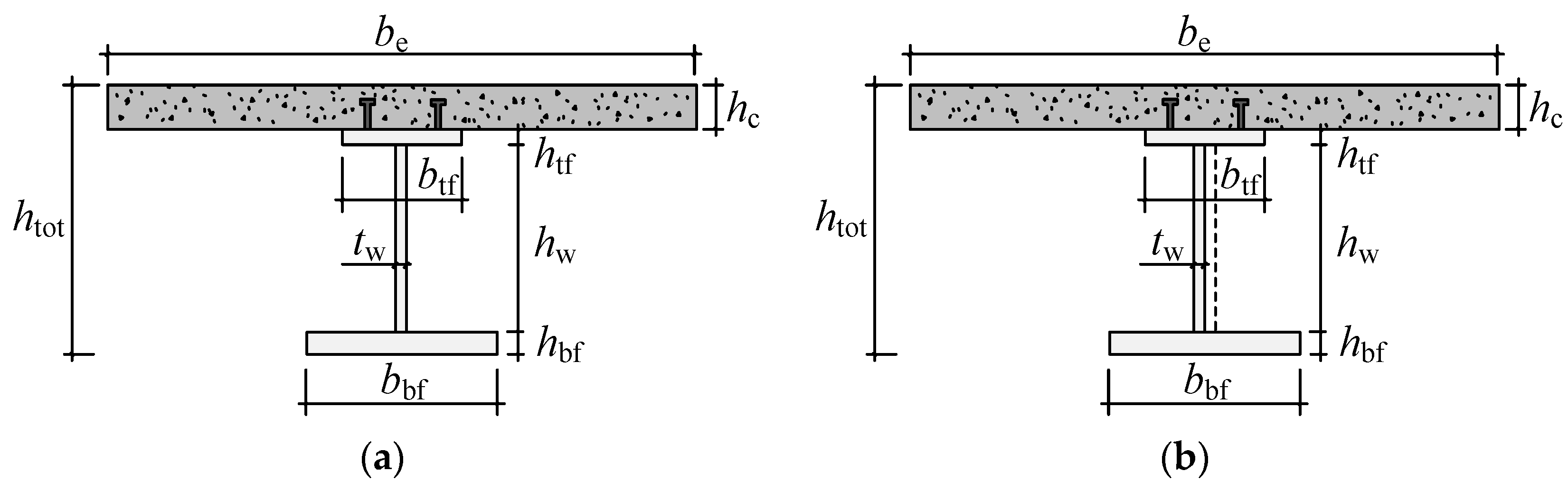
The composite cross-sections of Case I and Case II are illustrated in Figure 2, in which be and htot represent the effective width of the concrete slab and the total height of the composite section, respectively. The optimization variables, including the intermediate distance between the steel beams (B), the thickness of the concrete slab (hc) and six parameters concerning the dimensions of the steel section, are denoted by
3.2. Assumptions
According to the relevant design codes for composite structures [21,23,24], the designs of composite floor systems are based on plastic theory analyses. Assumptions 1–4 are applied for both Case I and Case II:
(1) The concrete slab and the steel section are fully shear connected.
(2) The tensile strength of the concrete is neglected.
(3) The concrete under compression is uniformly compressed to its design strength fc and the steel member is assumed to its design strength f in tension or compression.
(4) The effective width of the concrete slab is
Based on technical specifications [25] and design theories [26] for corrugated web structures, assumptions 5–6 are applied for Case II only:
(5) The corrugated web bears shear force only and its contribution to flexural resistance is neglected.
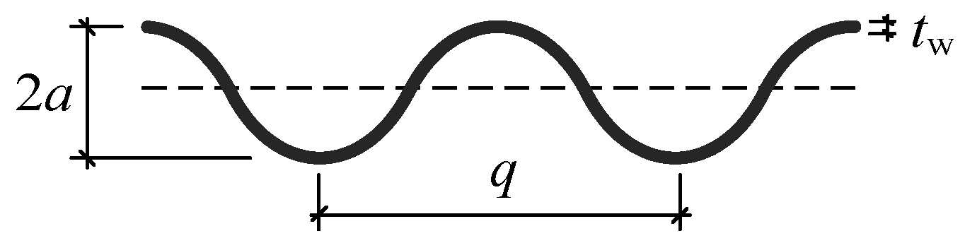
(6) The sinusoidal web (Figure 3) is considered only because its commonly used thickness is more suitable for floor systems and the properties of the sinusoidal section are described as follows:
where s is the unfolded length of a single sinusoidal wave, q is the wave length of a single sinusoidal wave, and a is the amplitude of the sinusoidal wave. Iz is the out-of-plain moment of inertia per unit length of the corrugated web about the neutral axis.
It is noticed that the linear form of the corrugated web requires additional steel compared with that of the flat web. Therefore, the cross-sectional area of the corrugated web beams is
where Atf, Aw and Abf denote the cross-sectional area of the top flange, web and bottom flange of the steel beam, respectively. Χ is a coefficient with respect to the corrugated web form and is defined as χ = s/q. In the optimization of Case II, it is satisfactory to consider a typical corrugated web form with q = 300 mm and a = 55 mm [25,26], which gives χ = 1.27.
3.3. Constraints
The optimization constraints are established based on plastic design theory and specifications, with reference to some experiential requirements in construction. Due to the different configuration of the steel beams, a few constraint functions applied in Case I and Case II are theoretically different, which will be specifically stated.
- (1)
- The design of beams for flexure is based on the following relationship
- For the design of composite floors with welded I-beams (Case I),
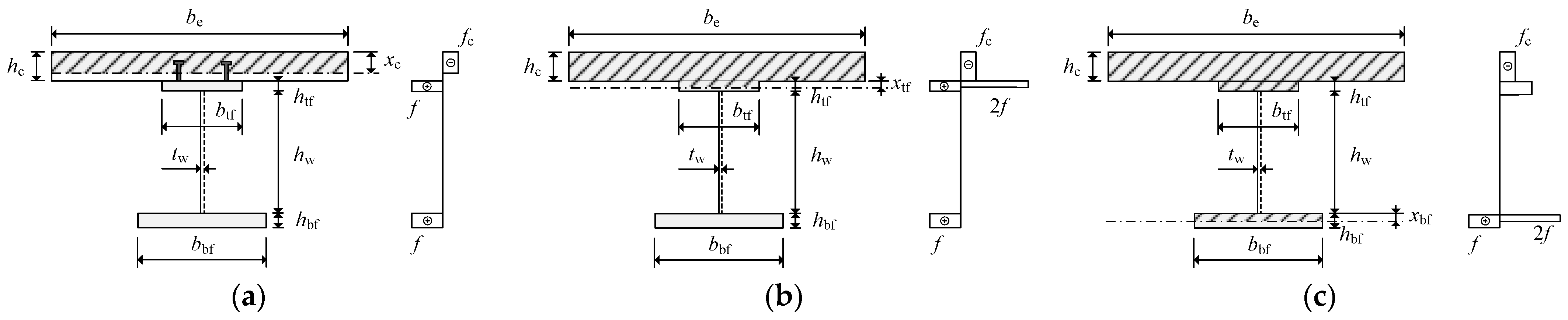
(a) when the plastic neutral axis located within the concrete slab (Asf ≤ behcfc):
where xc is the height of the compressed concrete, given by .
(b) when the plastic neutral axis located within the upper flange of the steel beam (Asf − 2btfhtff ≤ behcfc < Asf):
where xtf is the height of the compressed steel in the upper flange, given by .
(c) when the plastic neutral axis located within the web of the steel beam (Asf − 2btfhtff − 2hwtwf < behcfc ≤ Asf − 2btfhtff)
where xw is the height of the compressed steel in web, given by .
- For the design of composite floors with corrugated web beams (Case II),
(a) when the plastic neutral axis located within the concrete slab ((Atf + Abf) f ≤ behcfc):
where xc is the height of the compressed concrete, given by .
(b) when the plastic neutral axis located within the upper flange of the corrugated steel beam ((Abf − Atf) f ≤ behcfc < (Atf + Abf) f):
where xtf is the height of the compressed steel in the upper flange of the beam, given by .
(c) when the plastic neutral axis located within the bottom flange of the corrugated steel beam (behcfc < (Abf − Atf) f):
where xbf is the height of the compressed steel in the bottom flange of the beam, given by .
- (2)
V ≤ (φs)Awfv
- (3)
- (4)
- The upper flanges of the steel beams should not be too small, which are constrained by the sectional area ratio of the upper flanges and the bottom flanges:
- (5)
- The intermediate distance between steel members and the thickness of the concrete slab are constrained regarding construction experience:
- (6)
- The height of the composite beam is constrained by the height-to-span ratio [3]:htot/L ≤ 1/20
3.4. Optimization Method
To deal with the non-linear programming problem constructed above, the generalized gradient reduced (GRG) method is considered for its efficiency and robustness [28,29,30,31] in solving continuous optimization problems. A brief introduction is presented here with reference to [32] to give some heuristic insight into the method. Consider the typical form for a non-linear programming problem:
where X is a vector of continuous variables. Functions f(X), hj(X) and lk(X) are objective function, inequality constraints and equality constraints, respectively, and must be differentiable and continuous. xi(l) and xi(u) represent the lower and upper boundaries of the ith variable, respectively.
Minimize f(X)
s.t. hj(X) ≤ 0, j = 1, 2, 3, …, m
lk(X) = 0, k = 1, 2, 3, …, l
xi(l) ≤ xi ≤ xi(u), i = 1, 2, 3, …, n
By adding a nonnegative slack variable xn + j to each of the inequality constraints hj(X), the Equation (24) turns to equality constraints as
The above problem can then be described as
Minimize f(X)
s.t. gj(X) = 0, j = 1, 2, 3, …, m + l
xi(l) ≤ xi ≤ xi(u), i = 1, 2, 3, …, n + m
The variable X can be divided into two sets as X = [Y, Z]T, in which Y is independent variables obtained by subtraction from the set xi (i = 1, 2, …, n + m) for each of the m + l equality constraints, Y = [y1, y2, y3, …, yn − l]T; Z is dependent variables satisfying the constraints gj(X) = 0 (x = 1, 2, 3, …, m + l), Z = [z1, z2, z3, …, zm + l]T.
Then GRG algorithm tries to find a direction with respect to the independent variables that will improve the objective function. The direction is determined by the reduced gradient as follows:
For a minimization problem, the negative of the reduced gradient gives the direction of steepest descent. The GRG algorithm terminates when the magnitude of the reduced gradient at the current point is sufficiently small, which can be verified to be same as the Kuhn–Tucker conditions to be satisfied at a relative minimum [32,33]. Otherwise, a suitable step length is solved by a Newton-type procedure and a one-dimensional search procedure is performed to find a new point in the direction of the reduced gradient (see [34] for detailed description). The process is repeated until a local minimum is achieved.
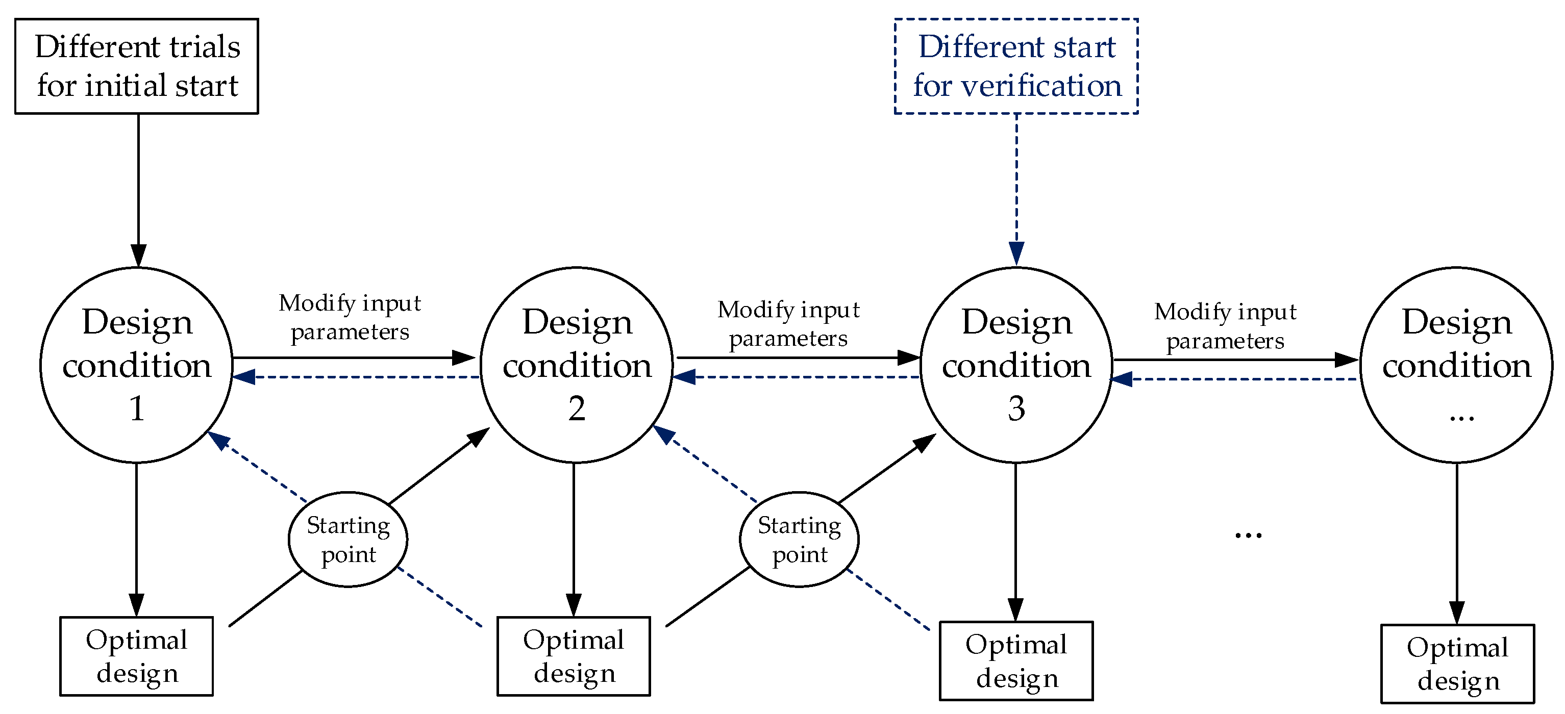
The execution of the GRG method is realized by GAMS/CONOPT [34]. In the process of optimization, the algorithm searches for the optimal combinations of the variables from an initial point which is input manually. Selecting a good starting point could make a difference in reducing the iterations and saving time and even affect the quality of the outcome. Considering that the cost-effectiveness of floor systems is investigated based on their optimal designs under various spans and live loads, a series of optimizations are generally required. Therefore, the optimal design results of the variables for the current design condition regarding span and live load can be used as the starting point for the next optimization in which a new design condition is adopted, as shown in Figure 6. In this way, the optimal design results of the composite floor systems are acquired consistently and effectively.
It should be noted that the optimization results acquired from the algorithm are not generally guaranteed as the global optimum since the problem involved is a nonconvex problem. In order to achieve the relative optimal results, different trials are supposed to be applied for the start of the general optimization procedure to ensure the value is relatively optimal. Also, the general optimization procedure can be initiated from different design conditions for further verifying the validity of the results.
With a series of optimal design results with spans ranging from 20 to 100 m and live loads ranging from 2 to 10 kN/m2, the cost-effectiveness and comparative study of the two composite floor systems are investigated thereafter. Apart from the cross-sectional dimensions that could be used as recommendations for design, the increasing variations in several indexes associated with variables are further introduced and compared, by which the economical difference of the discussed composite floors are demonstrated.
4. Optimization Results
4.1. Optimal Cross-Sections
The optimal design results of the studied composite floor systems with different combinations of spans and live loads are illustrated in Table 1 and Table 2, where the general steel consumption and sectional dimensions corresponding to the optimal designs are presented.
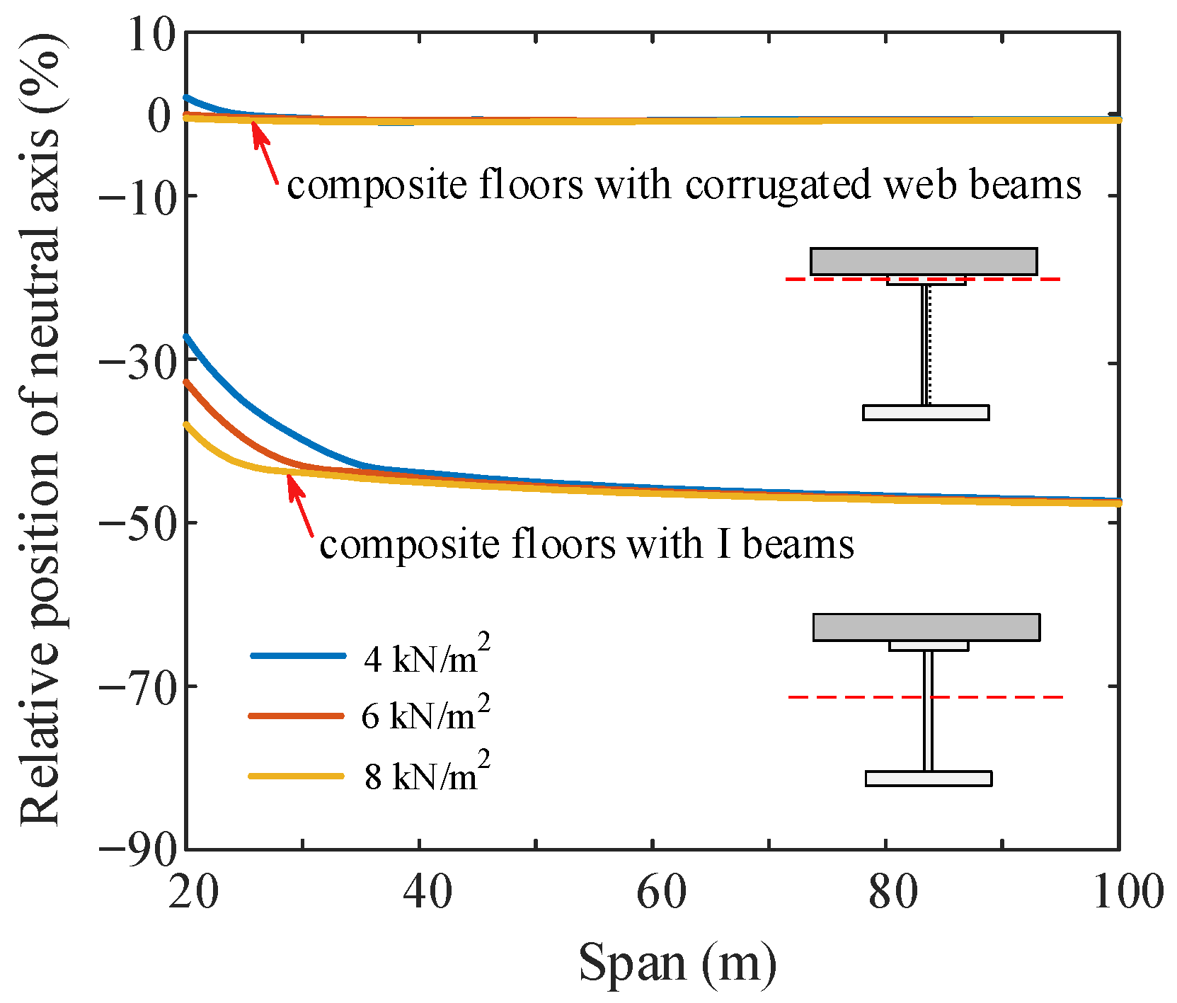
The optimization results demonstrate the similar features and specific differences for the optimal cross-sections of the two studied composite floor systems. It can be seen from Table 1 and Table 2 that the optimized steel sections are unanimously subjected to the width-to-thickness ratio to acquire higher flexural resistance with minimum material, which reconciles with the engineering cognition. Noting that the corrugation of the steel web makes a significant difference to the sectional dimensions, the thicknesses of corrugated webs are considerably thinner than those of flat webs in I-beams. The optimized examples show that the more effective way to increase flexural resistance in the composite I-beam is to make more use of the bottom flange rather than enlarging the steel web, whose thickness is subjected to a stricter height-to-thickness ratio. On the contrary, the corrugated web composite beam could easily obtain a more effective flexural resistance by a tall web without much additional steel consumption because the height-to-thickness ratio of the corrugated web is quite large. Consequently, the neutral plastic axes of the optimized sections are distributed differently for the two composite floor systems due to the different sectional developing rules, as shown in Figure 7, in which the position of the plastic axis is measured from the lower interface of the concrete slab. Figure 7 shows that the neutral plastic axes are located in the upper flanges for composite I sections and down in the middle of webs for corrugated web composite sections. With the plastic axis lying near the interface of concrete and steel, the composite floor with corrugated web beams could better realize the composite effect and achieve sufficient material savings.
4.2. General Steel Consumption
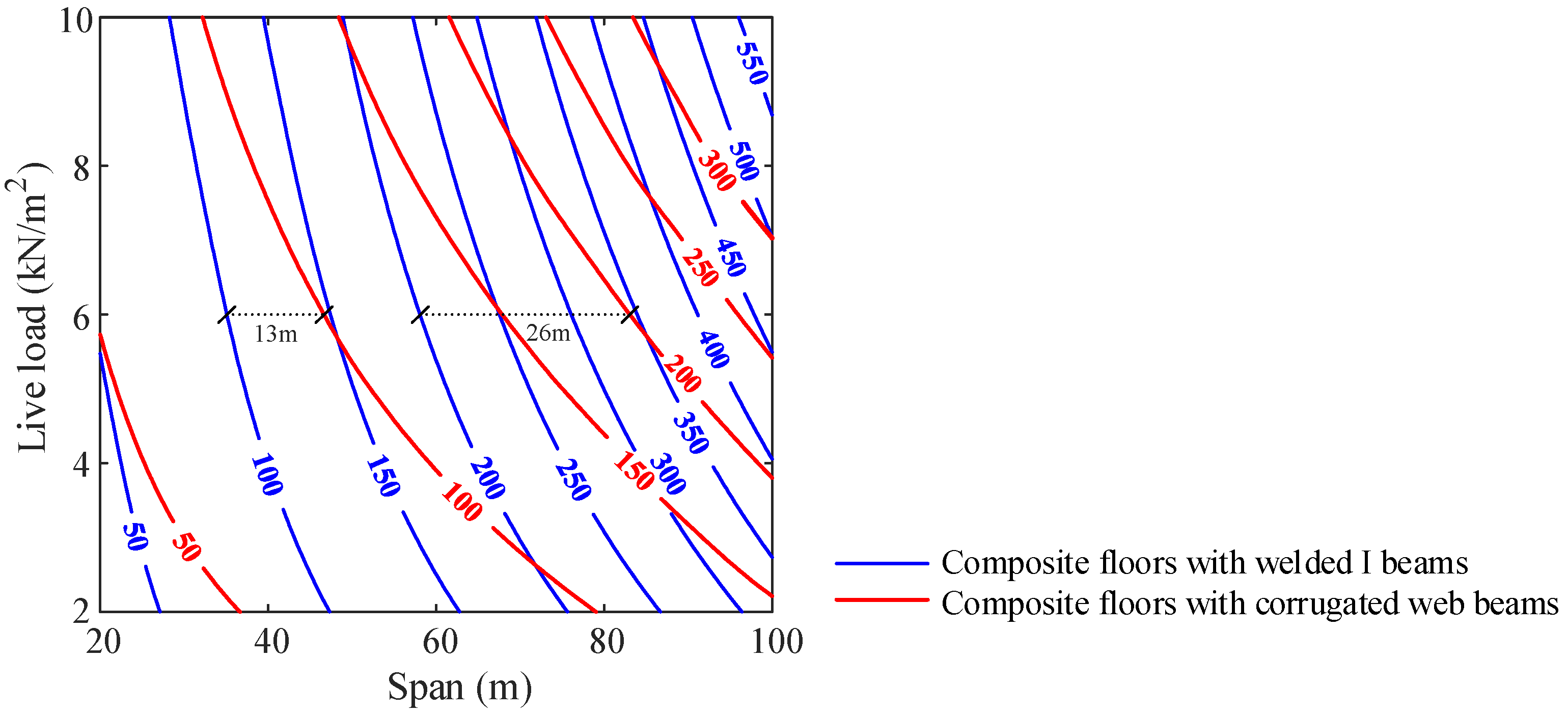
The optimization results of the general steel consumption are presented in the form of isolines in Figure 8 for various combinations of spans and live loads for the discussed composite floor systems. The isolines are drawn at every 50 kg/m2 of the objective function values and each isoline corresponds to multiple design conditions under equal steel consumption. The isolines themselves show that the impacts of design requirements to the studied composite floor systems produce different responses. Every isoline in red presents a more apparent degree of curvature, thus, a wider range of spans is economically permitted. This means that the composite floor system with corrugated web beams could be extensively applicable with proper material consumption. The distribution of the isolines also reflects the economical efficiencies of the two composite floor systems. It can be seen that the red isolines associated with composite floors with corrugated web beams are distributed less densely than the blue ones, which means the general steel consumption of composite floors with corrugated web beams increases more slowly than that of composite floors with welded I-beams, indicating the leading advantage in economic competitiveness for composite floor systems with corrugated web beams. In addition, the cost-effectiveness of composite floors with corrugated web beams further increases with the rise of the span. Taking the design condition of a live load of 6 kN/m2 for example, the economically optimal span of the composite floor with corrugated web beams exceeds the composite floor with I-beams by 13 m at an equivalent general steel consumption of 100 kg/m2 and 26 m at a steel consumption of 200 kg/m2, at which the permitted span of the composite floor with corrugated web beams achieves over 80 m.
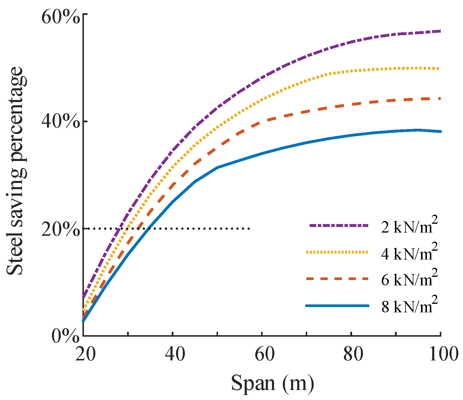
In order to illustrate the steel-saving effect of the composite floor with corrugated web beams, the steel-saving percentages are presented in Figure 9 by comparing the optimal steel consumption required for the two floor systems under the same design conditions. Figure 9 shows that the utilization of composite floors with corrugated web beams yields significant steel savings, ranging from 20% to 60% for large spans. Therefore, composite floors with corrugated web beams are recommended for use in large-span floor systems. Nevertheless, considering the convenience and lower construction and maintenance costs, the composite floor with I-beams can be recommended for spans that are less than 30 m, at which the steel-saving percentage rests at a relatively lower level of 20%.
4.3. Economical Efficiency of Composite Floors with Corrugated Web Beams
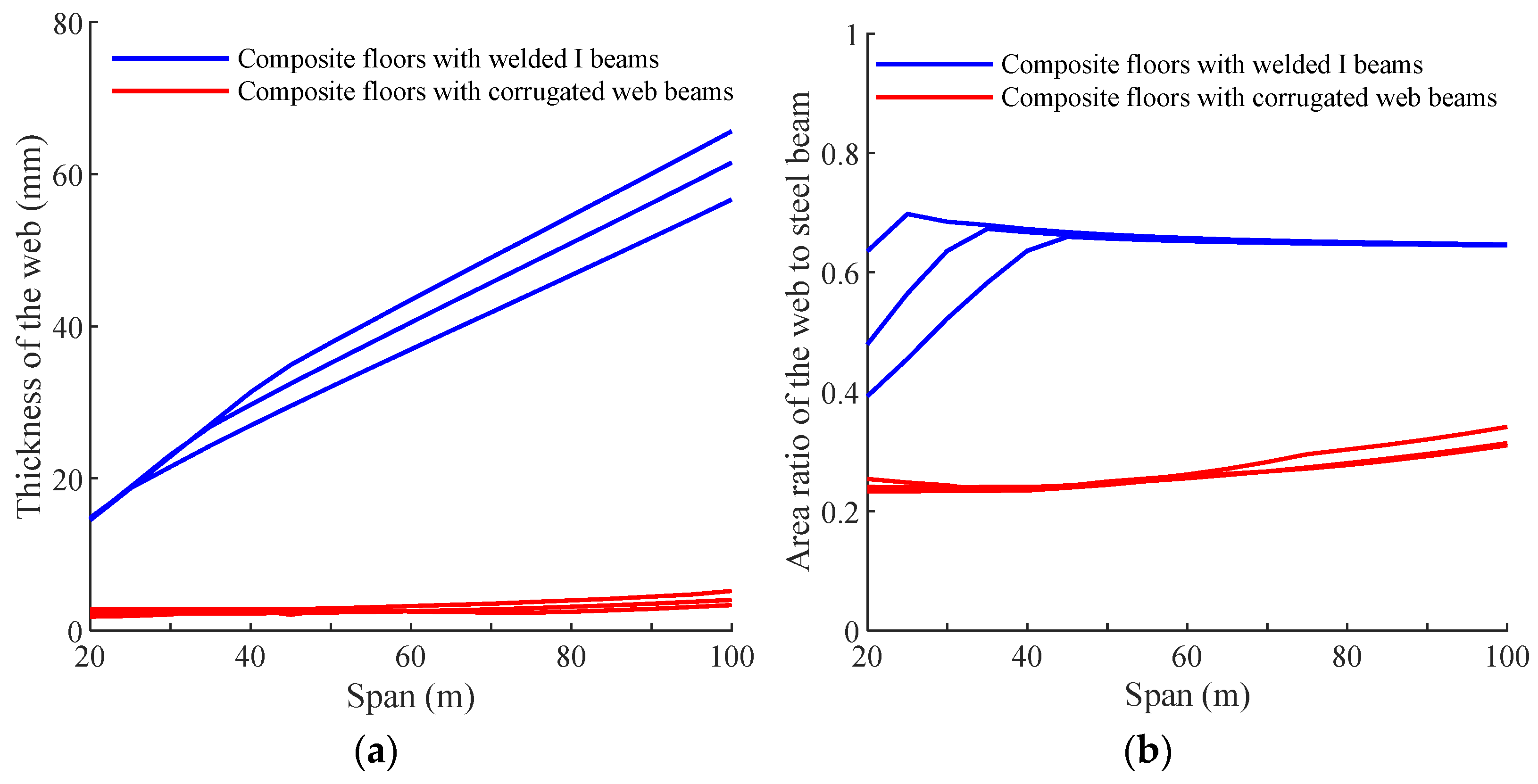
The significant economical efficiency of using composite floors with corrugated web beams results from the configuration of the steel web. The thickness required for the corrugated steel web is substantially less than that for the flat web, as shown in Figure 10a, which results in a great reduction in steel consumption of the web. Figure 10b illustrates the area ratio of the web section to the whole steel cross-section for the two floor systems. It is shown that the proportions of the corrugated webs steadily grow from a ratio of 0.2 to 0.3, while the proportions of the flat webs in I-beams rise rapidly to 0.7 at the span of 40 m and remain relatively constant thereafter.
The comparison of the steel proportion from the web reveals the economic efficiency of the composite floor with corrugated web beams. The underlying cause is related to the different shear design requirements of the two composite beams. The thickness of the web in traditional composite floors with I-beams is strongly determined by the constraint of geometric width-to-thickness ratio associated with stability and plastic development [35]. Thus, the thickness of the web can be considerably large due to the large cross-sectional height in large-span floor systems. In contrast, the design of the corrugated web is determined by the strength–stability combined with shear resistance instead of the width-to-thickness ratio [36,37]. The thickness of the corrugated web can be reasonably economical because the corrugated steel web has great stability performance and can make sufficient use of the shear strength under shear loads. Additionally, with rise of the span, the shear resistance for corrugated webs can be partially achieved by the growth in cross-sectional height, which helps keep the web thickness at an economical level. Moreover, the different shear design requirements also result in different intermediate distances of the steel beams, as in Table 1 the optimized distance values remain at 6 m while in Table 2 the values vary at first and stay at 2.5 m for large-span designs. With the aim of an economically optimal design, composite floors with corrugated web beams could bear lighter imposed loads by adjusting the intermediate distance of steel beams to achieve the small web thickness for shear. Therefore, the steel proportion of the corrugated web remains at a reasonable and economical value for composite floors with corrugated web beams, which greatly enhances economic efficiency.
5. Discussions on Design of Super-Large Span Composite Floor System
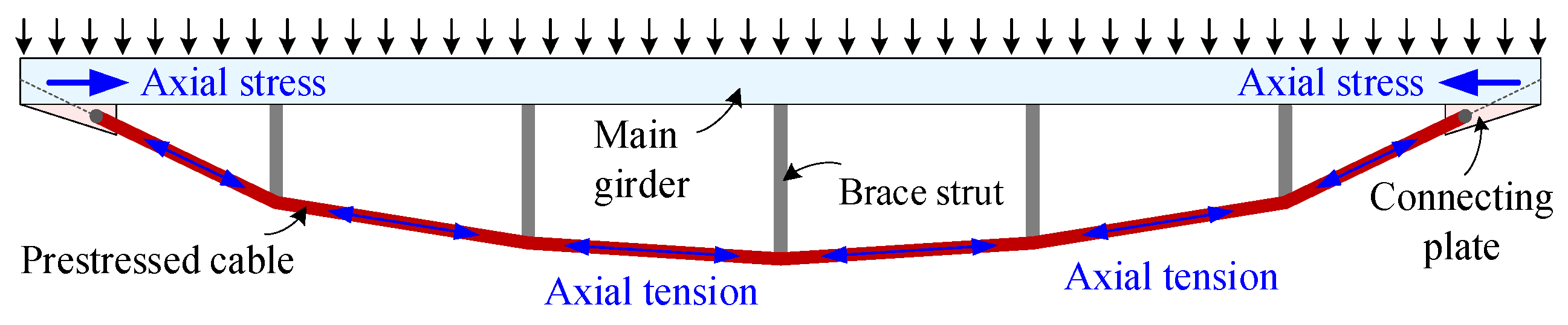
Based on the previous results and discussions, an effective way for designing a super-large-span composite floor system is to enhance the flexural-resistant efficiency and to decrease the steel proportion of the web that has relatively lower flexural bearing efficiency. Considering such a design concept, a new cable-supported steel–concrete composite floor system is recommended by the authors. This structural form is developed from the string beam structure [38] as shown in Figure 11, which simplifies the web form and receive sectional depth from struts that connect the compressed main girder and the prestressed cable. The stress in the girder and tension in the cable act together to significantly resist vertical loads. The structural configuration and high-bearing efficiency of the string beam contribute to its simple and elegant appearance, and has provided great economic benefits in the applications of large-span roof structures [39,40,41].
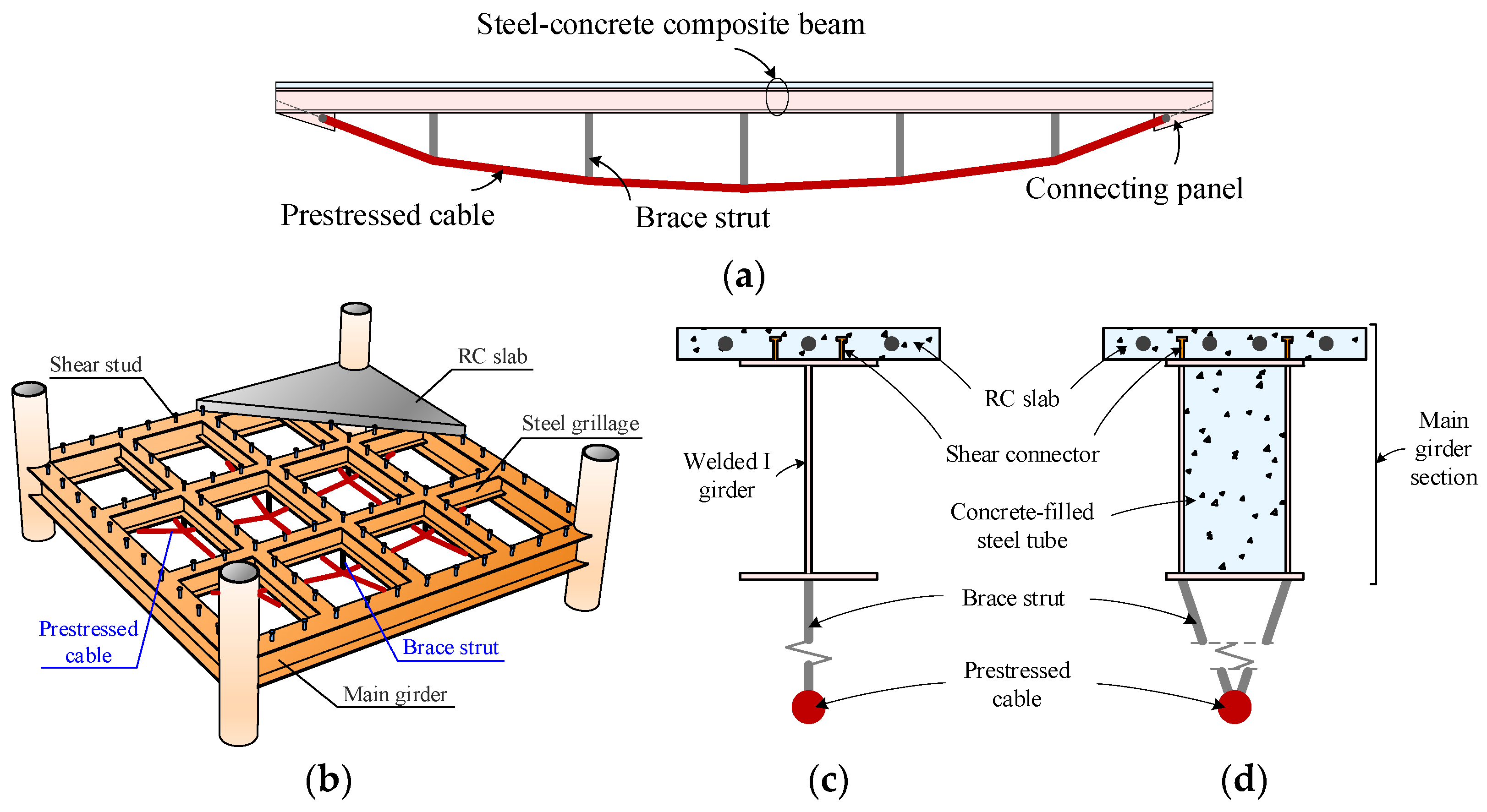
To effectively utilize the string beam in large-span floor structures, the key approach is to incorporate concrete into the main girder that is subjected to compression. Figure 12a,b show the cable-supported beam and floor system with traditional steel–concrete girder, which have been used in bridge and roof structures and received good benefits [42,43,44]. Figure 12d presents a novel cross-section design for the cable-supported steel-concrete composite beam, which utilizes concrete-filled steel tube (CFST) in the main girder cross-section. Compared with the beam using traditional composite girder in Figure 12c, the beam with composite girder using CFST could greatly enhance its resistance to axial compression and negative bending moment, while also avoiding the probable stability issues caused by the prestressed I-girder. Therefore, the design of the cable-supported composite beam as shown in Figure 12d can adopt larger cable cross-sectional area and initial prestress, thereby significantly improving the bearing capacity and applicable span of the cable-supported composite beam.
To summarize, the development of a new cable-supported steel–concrete composite beam not only inherits the advantages of the high mechanical performance for string beam structures, but also fully exploits the composite effect of steel–concrete composite structures. Consequently, the bearing capacity, spanning capability, and vibration serviceability of the floor system are enhanced. Therefore, research on the novel cable-supported steel–concrete composite beam (or floor system) offers great potential and promote its application in super-large floor structures.
6. Conclusions
This paper investigates an optimal design comparison between composite floor systems with welded I-beams and corrugated web beams, considering parameters of live loads ranging from 2 to 10 kN/m2 and spans ranging from 20 to 100 m. The main findings can be summarized as follows:
- The composite floor with welded I-beams requires a larger cross-sectional area while the composite floor with corrugated web beams is more adaptable for different design conditions with an economical section. By sensibly adjusting the sectional dimensions and the distribution of the steel beams, a reasonable position of the plastic neutral axis can be realized for composite floors with corrugated web beams. In this way, the composite effect and flexural bearing efficiency of the system can be well achieved.
- The optimization results of the cross-sectional dimensions show that the thicknesses of corrugated webs determined by strength and stability are considerably thinner than those of flat webs determined by geometric width-to-thickness ratio. Because of this, the web area accounts for only 20–30% of the corrugated web beam, while accounting for 40–70% of the I-beam. The difference in web area leads to a great reduction in general steel consumption for composite floors with corrugated web beams.
- The effectiveness in load-carrying behavior and material saving enable a better spanning capability for the composite floor with corrugate web beams. In addition, it remains cost-effective under design conditions of large spans and heavy loads. Compared with composite floors with I-beams, composite floors with corrugated web beams could save 20–60% material without weakening the ultimate load-carrying capacity. Consequently, composite floors with corrugated web beams are recommended for spans larger than 30 m (at which more than 20% in steel saving is achieved) due to the enormous economic efficiency. Composite floors with welded I-beams remain competitive for spans less than 30 m considering the simpler configuration and wider use of flat-webbed I-beams.
- Upon examining our results following a comparative study and analysis, the key approach to improving the economic performance of a composite floor system is to reduce the proportion of the steel used in webs that have relatively low flexural bearing efficiency. Based on this concept, a new structural form of spatial floor system with cable-supported steel–concrete beam is introduced for super-large span structures. This spatially structured floor system promotes the conventional composite floor systems by simplifying the web form and replacing the bottom flange with a high-strength cable, producing significant applicable potential in super-large span floor structures.
Author Contributions
Conceptualization, W.P. and Y.L.; methodology, W.P. and Y.W.; software, W.P., Y.W. and Y.L.; validation, Y.W. and W.P.; formal analysis, W.P. and Y.W.; investigation, Y.W. and W.P.; resources, W.P. and Y.L.; data curation, W.P. and Y.W.; writing—original draft preparation, Y.W.; writing—review and editing, W.P. and Y.W.; visualization, Y.W.; supervision, W.P. and Y.L.; project administration, W.P. and Y.L.; funding acquisition, W.P. All authors have read and agreed to the published version of the manuscript.
Funding
This research was funded by the National Natural Science Foundation of China (Grant No. 52108181) and Zhejiang Provincial Natural Science Foundation of China (Grant No. LQ21E080020). This work was also supported by the Center for Balance Architecture of Zhejiang University (Grant No. K20212819).
Data Availability Statement
The data presented in this study are available on request from the corresponding author.
Conflicts of Interest
The authors declare no conflict of interest.
References
- Dong, S.; Zhao, Y.; Xing, D. Application and Development of Modern Long-Span Space Structures in China. Front. Struct. Civ. Eng. 2012, 6, 224–239. [Google Scholar] [CrossRef]
- Johnson, R.P. Composite Structures of Steel and Concrete: Beams, Slabs, Columns and Frames for Buildings, 4th ed.; John Wiley & Sons: Hoboken, NJ, USA, 2018. [Google Scholar]
- Nie, J.; Liu, M.; Ye, L. Steel-Concrete Composite Structures; China Architecture & Building Press: Beijing, China, 2005. (In Chinese) [Google Scholar]
- Nie, J.; Wang, J.; Gou, S.; Zhu, Y.; Fan, J. Technological Development and Engineering Applications of Novel Steel-Concrete Composite Structures. Front. Struct. Civ. Eng. 2019, 13, 1–14. [Google Scholar] [CrossRef]
- Tao, M.; Nie, J.; Fan, J.; Pan, W.; Wang, J.; Liu, C. Development Trends and Path for China’s Civil and Structural Engineering Science and Technology to 2035. Chin. J. Eng. Sci. 2017, 19, 73. [Google Scholar]
- Kaveh, A.; Ahangaran, M. Discrete Cost Optimization of Composite Floor System Using Social Harmony Search Model. Appl. Soft Comput. 2012, 12, 372–381. [Google Scholar] [CrossRef]
- Poitras, G.; Lefrançois, G.; Cormier, G. Optimization of Steel Floor Systems Using Particle Swarm Optimization. J. Constr. Steel Res. 2011, 67, 1225–1231. [Google Scholar] [CrossRef]
- Kaveh, A.; Massoudi, M.S. Cost optimization of a composite floor system using ant colony system. Iran. J. Sci. Technol. Trans. Civ. Eng. 2012, 36, 139–148. [Google Scholar]
- Senouci, A.B.; Al-Ansari, M.S. Cost Optimization of Composite Beams Using Genetic Algorithms. Adv. Eng. Softw. 2009, 40, 1112–1118. [Google Scholar] [CrossRef]
- Korouzhdeh, T.; Eskandari-Naddaf, H.; Gharouni-Nik, M. An Improved Ant Colony Model for Cost Optimization of Composite Beams. Appl. Artif. Intell. 2017, 31, 44–63. [Google Scholar]
- Kravanja, S.; Šilih, S. Optimization Based Comparison between Composite I Beams and Composite Trusses. J. Constr. Steel Res. 2003, 59, 609–625. [Google Scholar] [CrossRef]
- Kravanja, S.; Žula, T.; Klanšek, U. Multi-Parametric MINLP Optimization Study of a Composite I Beam Floor System. Eng. Struct. 2017, 130, 316–335. [Google Scholar] [CrossRef]
- Elgaaly, M.; Seshadri, A.; Hamilton, R.W. Bending Strength of Steel Beams with Corrugated Webs. J. Struct. Eng. 1997, 123, 772–782. [Google Scholar] [CrossRef]
- Johnson, R.P.; Cafolla, J.; Bernard, C. Corrugated Webs in Plate Girders for Bridges. Proc. Inst. Civ. Eng. Struct. Build. 1997, 122, 157–164. [Google Scholar] [CrossRef]
- Jiang, R.J.; Kwong Au, F.T.; Xiao, Y.F. Prestressed Concrete Girder Bridges with Corrugated Steel Webs: Review. J. Struct. Eng. 2015, 141, 04014108. [Google Scholar] [CrossRef]
- Hassanein, M.F.; Elkawas, A.A.; El Hadidy, A.M.; Elchalakani, M. Shear Analysis and Design of High-Strength Steel Corrugated Web Girders for Bridge Design. Eng. Struct. 2017, 146, 18–33. [Google Scholar] [CrossRef]
- Leblouba, M.; Junaid, M.T.; Barakat, S.; Altoubat, S.; Maalej, M. Shear Buckling and Stress Distribution in Trapezoidal Web Corrugated Steel Beams. Thin-Walled Struct. 2017, 113, 13–26. [Google Scholar] [CrossRef]
- Wang, Z.-Y.; Li, X.; Gai, W.; Jiang, R.; Wang, Q.-Y.; Zhao, Q.; Dong, J.; Zhang, T. Shear Response of Trapezoidal Profiled Webs in Girders with Concrete-Filled RHS Flanges. Eng. Struct. 2018, 174, 212–228. [Google Scholar] [CrossRef]
- Erdal, F.; Tunca, O.; Ozcelik, R. Experimental Investigation and Numerical Analysis of Optimally Designed Composite Beams with Corrugated Steel Webs. Steel Compos. Struct. 2020, 37, 1–14. [Google Scholar]
- Leblouba, M.; Karzad, A.S.; Tabsh, S.W.; Barakat, S. Plated versus Corrugated Web Steel Girders in Shear: Behavior, Parametric Analysis, and Reliability-Based Design Optimization. Buildings 2022, 12, 2046. [Google Scholar] [CrossRef]
- GB 50010-2010; Code for Design of Concrete Structures. Standardization Administration of the People’s Republic of China: Beijing, China, 2015. (In Chinese)
- Wu, Y.; Pan, W.; Luo, Y. Optimal Design of Long Span Steel-Concrete Composite Floor System. J. ZheJiang Univ. Eng. Sci. 2023, 57, 1–9. (In Chinese) [Google Scholar]
- JGJ 138-2016; Code for Design of Composite Structures. Standardization Administration of the People’s Republic of China: Beijing, China, 2016. (In Chinese)
- GB 50017-2017; Standard for Design of Steel Structures. Standardization Administration of the People’s Republic of China: Beijing, China, 2017. (In Chinese)
- CECS290: 2011; Technical Specification for Application of Sinusoidal Web Steel Structures. Standardization Administration of the People’s Republic of China: Beijing, China, 2012. (In Chinese)
- Guo, Y.; Tong, J.; Jiang, Z. Design Fundamentals and Application of Corrugated-Web Steel Structure; Beijing Science Press: Beijing, China, 2015. (In Chinese) [Google Scholar]
- Sun, Y.; He, A.; Liang, Y.; Zhao, O. In-Plane Bending Behaviour and Capacities of S690 High Strength Steel Welded I-Section Beams. J. Constr. Steel Res. 2019, 162, 105741. [Google Scholar] [CrossRef]
- Lasdon, L.S.; Waren, A.D.; Jain, A.; Ratner, M. Design and Testing of a Generalized Reduced Gradient Code for Nonlinear Programming. ACM Trans. Math. Softw. 1978, 4, 34–50. [Google Scholar] [CrossRef]
- Del Castillo, E.; Montgomery, D.C. A Nonlinear Programming Solution to the Dual Response Problem. J. Qual. Technol. 1993, 25, 199–204. [Google Scholar] [CrossRef]
- Köksoy, O. A Nonlinear Programming Solution to Robust Multi-Response Quality Problem. Appl. Math. Comput. 2008, 196, 603–612. [Google Scholar] [CrossRef]
- Ebid, A.M. Optimum Cross Section and Longitudinal Profile for Unstiffened Fully Composite Steel Beams. Future Eng. J. 2021, 2, 2314–7237. [Google Scholar]
- Rao, S.S. Engineering Optimization: Theory and Practice, 5th ed.; John Wiley & Sons: Hoboken, NJ, USA, 2019. [Google Scholar]
- Gabriele, G.A. Large-Scale Nonlinear Programming Using the Generalized Reduced Gradient Method. Ph.D. Thesis, Purdue University, West Lafayette, IN, USA, 1980. [Google Scholar]
- Drud, A. CONOPT: A GRG Code for Large Sparse Dynamic Nonlinear Optimization Problems. Math. Program. 1985, 31, 153–191. [Google Scholar] [CrossRef]
- Zhao, J.; Li, J.; Sun, Y. Experimental and Numerical Study on Overall Buckling Behavior of Q460 High-Strength Steel Continuous Beams with Welded Singly Symmetric I-Section. Eng. Struct. 2023, 280, 115678. [Google Scholar] [CrossRef]
- Khalid, Y.A.; Chan, C.L.; Sahari, B.B.; Hamouda, A.M.S. Bending Behaviour of Corrugated Web Beams. J. Mater. Process. Technol. 2004, 150, 242–254. [Google Scholar]
- Kövesdi, B.; Jáger, B.; Dunai, L. Bending and Shear Interaction Behavior of Girders with Trapezoidally Corrugated Webs. J. Constr. Steel Res. 2016, 121, 383–397. [Google Scholar] [CrossRef]
- Saitoh, M. Principle of Beam String Structure. Proc. of IASS (Madrid). 1979, 4, 17–38. [Google Scholar]
- Saitoh, M.; Okada, A. The Role of String in Hybrid String Structure. Eng. Struct. 1999, 21, 756–769. [Google Scholar] [CrossRef]
- Xue, W.; Liu, S. Design Optimization and Experimental Study on Beam String Structures. J. Constr. Steel Res. 2009, 65, 70–80. [Google Scholar] [CrossRef]
- Zhao, X.; Yan, S.; Xu, Z.; Wu, A. Research and Application of Beam String Structures. Struct. Eng. Int. 2015, 25, 26–33. [Google Scholar] [CrossRef]
- Ruiz-Teran, A.M.; Aparicio, A.C. Two New Types of Bridges: Under-Deck Cable-Stayed Bridges and Combined Cable-Stayed Bridges—the State of the Art. Can. J. Civ. Eng. 2007, 34, 1003–1015. [Google Scholar] [CrossRef] [Green Version]
- An, Q.; Chen, Z.; Ren, Q.; Liu, H.; Yan, X. Control of Human-Induced Vibration of an Innovative CSBS–CSCFS. J. Constr. Steel Res. 2015, 115, 359–371. [Google Scholar] [CrossRef]
- An, Q.; Ren, Q.; Liu, H.; Yan, X.; Chen, Z. Dynamic Performance Characteristics of an Innovative Cable Supported Beam Structure–Concrete Slab Composite Floor System under Human-Induced Loads. Eng. Struct. 2016, 117, 40–57. [Google Scholar] [CrossRef]
Figure 1.
Steel–concrete composite floors for optimization: (a) simply supported steel–concrete composite beam; (b) composite floor with welded I-beams; (c) composite floor with corrugated web beams.
Figure 1.
Steel–concrete composite floors for optimization: (a) simply supported steel–concrete composite beam; (b) composite floor with welded I-beams; (c) composite floor with corrugated web beams.

Figure 2.
Cross-sections of the studied composite beams: (a) composite beam with welded I-section; (b) composite beam with corrugated web.
Figure 2.
Cross-sections of the studied composite beams: (a) composite beam with welded I-section; (b) composite beam with corrugated web.

Figure 3.
Cross-section of corrugated steel web.

Figure 4.
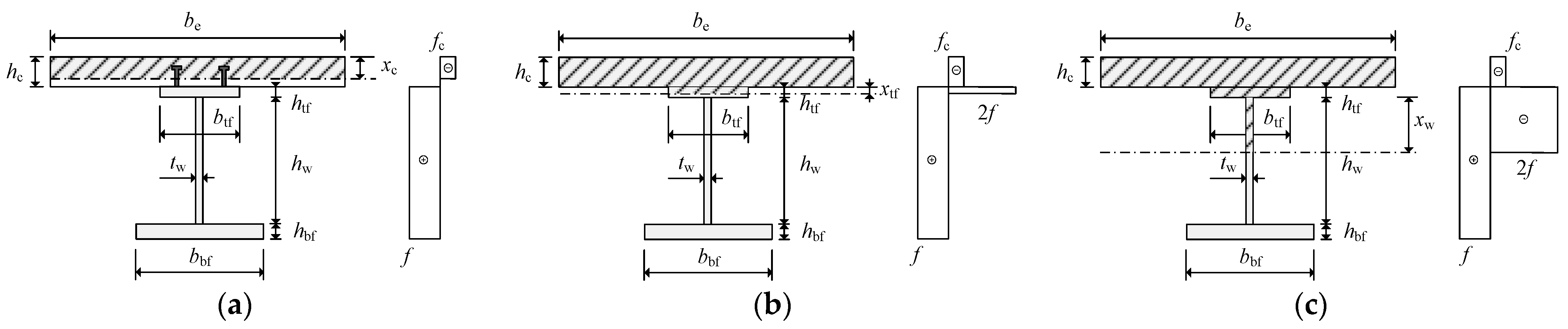
Plastic neutral axis located within (a) concrete slab, (b) upper flange of steel beam and (c) web of steel beam for design of composite floors with welded I-beams (Case I).
Figure 4.
Plastic neutral axis located within (a) concrete slab, (b) upper flange of steel beam and (c) web of steel beam for design of composite floors with welded I-beams (Case I).

Figure 5.
Plastic neutral axis located within (a) concrete slab, (b) upper flange of steel beam and (c) bottom flange of steel beam for design of composite floors with corrugated web beams (Case II).
Figure 5.
Plastic neutral axis located within (a) concrete slab, (b) upper flange of steel beam and (c) bottom flange of steel beam for design of composite floors with corrugated web beams (Case II).

Figure 6.
General optimization procedure for optimal designs under various design conditions.

Figure 7.
Relative position of plastic neutral axis to whole section.

Figure 8.
Isolines of the general steel consumption of composite floors with welded I-beams and corrugated web beams (unit: kg/m2).
Figure 8.
Isolines of the general steel consumption of composite floors with welded I-beams and corrugated web beams (unit: kg/m2).

Figure 9.
Steel-saving percentages of composite floors with corrugated web beams.

Figure 10.
Optimized size of web with a live load of 4, 6 and 8 kN/m2: (a) thickness of web; (b) area ratio of web to whole section.
Figure 10.
Optimized size of web with a live load of 4, 6 and 8 kN/m2: (a) thickness of web; (b) area ratio of web to whole section.

Figure 11.
Demonstration of the string beam structure.

Figure 12.
Cable-supported (a) beam and (b) floor system with traditional composite girder; cross-section of beam with composite girder using (c) welded I-girder and (d) concrete-filled steel tube (CSFT).
Figure 12.
Cable-supported (a) beam and (b) floor system with traditional composite girder; cross-section of beam with composite girder using (c) welded I-girder and (d) concrete-filled steel tube (CSFT).


Table 1.
Optimal designs for composite floor systems with welded I-beams.
| Live Loads (kN/m2) | L = 20 m | L = 30 m | L = 40 m | L = 50 m | L = 60 m | L = 70 m | L = 80 m | L = 90 m | L = 100 m |
|---|---|---|---|---|---|---|---|---|---|
| 2 | 36.93 6.0/100 133.3/8.1 817.2/13.9 185.5/11.7 | 56.06 6.0/100 217.2/13.6 1094.7/18.7 303.2/19.4 | 79.88 6.0/100 284.1/17.8 1376.1/23.5 396.7/25.5 | 107.94 6.0/100 367.4/23.2 1645.4/28.1 470.4/30.2 | 140.24 6.0/100 450.1/28.5 1906.7/32.5 540.2/34.7 | 177.09 6.0/100 529.8/33.7 2166.1/37.0 609.9/39.1 | 218.96 6.0/100 608.1/38.7 2427.4/41.4 680.3/43.6 | 266.41 6.0/100 686.4/43.7 2692.7/46.0 752.1/48.2 | 320.10 6.0/100 765.5/48.8 2964.5/50.6 825.7/52.9 |
| 4 | 44.33 6.0/100 197.9/12.5 869.7/14.8 276.4/17.9 | 69.63 6.0/100 257.9/16.1 1261.4/21.5 360.1/23.1 | 100.51 6.0/100 345.8/21.8 1579.0/27.0 452.8/29.1 | 136.28 6.0/100 440.8/27.9 1876.7/32.0 532.2/34.1 | 177.04 6.0/100 529.7/33.6 2165.8/37.0 609.8/39.1 | 223.09 6.0/100 615.3/39.2 2451.5/41.8 686.9/44.0 | 274.87 6.0/100 699.5/44.6 2737.3/46.7 764.2/49.0 | 332.93 6.0/100 783.2/50.0 3025.9/51.7 842.3/54.0 | 397.92 6.0/100 867.4/55.4 3319.0/56.7 922.2/59.1 |
| 6 | 52.08 6.0/100 265.6/17.1 858.4/14.7 372.5/24.4 | 81.98 6.0/100 306.9/19.4 1352.9/23.1 429.1/27.7 | 118.95 6.0/100 397.4/25.1 1739.0/29.7 495.3/31.8 | 81.98 6.0/100 306.9/19.4 1352.9/23.1 429.1/27.7 | 209.76 6.0/100 591.8/37.6 2372.4/40.5 665.5/42.7 | 161.54 6.0/100 497.7/31.6 2060.6/35.2 581.5/37.3 | 324.42 6.0/100 771.5/49.2 2985.3/51.0 831.4/53.3 | 263.92 6.0/100 682.5/43.5 2679.4/45.7 748.5/48.0 | 466.70 6.0/100 948.5/60.6 3604.0/61.5 999.2/64.0 |
| 8 | 60.28 5.8/100 312.7/20.4 850.6/14.5 439.8/29.0 | 94.45 6.0/100 402.9/25.9 1340.3/22.9 517.9/33.8 | 135.96 6.0/100 457.5/29.1 1835.4/31.3 550.6/35.5 | 184.71 6.0/100 544.9/34.6 2216.0/37.8 623.4/40.0 | 239.76 6.0/100 643.6/41.0 2547.0/43.5 712.7/45.7 | 301.29 6.0/100 738.7/47.1 2872.2/49.0 800.7/51.3 | 369.73 6.0/100 831.9/53.1 3194.7/54.5 888.9/57.0 | 445.58 6.0/100 924.3/59.0 3518.9/60.1 976.3/62.6 | 529.47 6.0/100 1016.8/64.9 3845.6/65.6 1064.7/68.2 |
| 10 | 68.64 4.9/100 313.0/20.4 850.6/14.5 439.5/29.0 | 107.20 6.0/100 483.2/31.4 1329.7/22.7 591.7/38.9 | 152.88 6.0/100 552.2/35.6 1822.6/31.1 643.7/41.8 | 206.40 6.0/100 600.8/38.3 2318.2/39.6 676.6/43.5 | 267.74 6.0/100 688.5/43.9 2699.8/46.1 754.0/48.3 | 336.13 6.0/100 787.6/50.2 3040.9/51.9 846.5/54.3 | 411.92 6.0/100 884.4/56.5 3378.9/57.7 938.5/60.1 | 495.62 6.0/100 980.5/62.6 3717.2/63.5 1029.9/66.0 | 587.84 6.0/100 1076.5/68.8 4057.4/69.3 1122.1/71.9 |
 | Legend | ||||||||
| 81.98 6.0/100 306.9/19.4 1352.9/23.1 429.1/27.7 | General steel consumption (kg/m2) B (m)/hc (mm) btf (mm)/htf (mm) hw (mm)/tw (mm) bbf (mm)/hbf (mm) | ||||||||
Table 2.
Optimal designs for composite floor systems with corrugated web beams.
| Live Loads (kN/m2) | L = 20 m | L = 30 m | L = 40 m | L = 50 m | L = 60 m | L = 70 m | L = 80 m | L = 90 m | L = 100 m |
|---|---|---|---|---|---|---|---|---|---|
| 2 | 34.73 3.3/100 161.1/10.9 873.7/1.6 227.4/15.4 | 43.92 4.5/100 235.3/15.9 1361.5/2.1 332.3/22.6 | 53.13 6.0/100 319.1/21.6 1847.8/2.7 450.7/30.6 | 63.14 5.8/100 354.4/24.0 2342.0/2.8 500.7/34.0 | 74.20 4.8/100 354.3/24.0 2842.0/2.5 500.5/34.0 | 86.70 4.0/100 354.2/24.0 3342.0/2.4 500.4/34.0 | 101.59 3.5/100 354.2/24.0 3842.0/2.3 500.4/34.0 | 120.14 3.0/100 354.3/24.0 4342.0/2.4 500.5/34.0 | 143.12 2.6/100 354.3/24.0 4842.0/2.6 500.6/34.0 |
| 4 | 42.88 2.5/100 171.6/11.6 872.0/1.8 242.4/16.4 | 56.48 3.0/100 235.4/15.9 1361.5/2.1 332.5/22.6 | 70.10 4.2/100 323.1/21.9 1847.1/2.8 456.4/31.0 | 84.93 4.0/100 354.4/24.0 2342.0/2.8 500.7/34.0 | 101.29 3.2/100 354.3/24.0 2842.0/2.5 500.5/34.0 | 119.80 2.7/100 354.2/24.0 3342.0/2.4 500.4/34.0 | 142.97 2.5/100 375.8/25.5 3539.3/2.5 517.6/35.2 | 171.89 2.5/100 424.8/28.8 4333.3/2.8 557.8/37.9 | 206.10 2.5/100 473.2/32.1 4827.3/3.3 598.7/40.7 |
| 6 | 51.14 2.5/100 199.7/13.5 867.4/2.3 281.9/19.1 | 69.03 2.5/100 247.3/16.7 1359.6/2.3 349.2/23.7 | 87.22 2.5/100 287.5/19.5 1852.9/2.2 406.2/27.6 | 106.98 2.5/100 323.9/22.0 2347.0/2.4 457.5/31.1 | 128.82 2.5/100 360.6/24.4 2841.2/2.5 505.5/34.3 | 157.25 2.5/100 418.3/28.4 3334.1/2.8 418.3/37.5 | 189.22 2.5/100 472.6/32.1 3827.3/3.1 472.6/40.6 | 225.72 2.5/100 525.3/35.6 4320.6/3.5 664.0/43.7 | 268.02 2.5/100 577.5/39.2 4814.0/4.0 690.3/46.9 |
| 8 | 59.58 2.5/100 224.8/15.2 863.4/2.8 317.3/21.5 | 81.61 2.5/100 277.2/18.7 1354.7/2.7 391.4/26.5 | 104.05 2.5/100 323.1/21.9 1847.1/2.8 323.1/31.0 | 129.51 2.5/100 363.2/24.6 2338.1/2.9 513.0/34.8 | 161.85 2.5/100 406.4/27.5 2818.8/3.2 574.1/39.0 | 197.47 2.5/100 448.5/30.4 3300.1/3.5 448.5/43.0 | 237.56 2.5/100 490.2/33.2 3781.5/3.9 692.4/47.0 | 283.14 2.5/100 532.1/36.0 4262.9/4.4 751.6/51.0 | 337.52 2.6/100 581.9/39.4 4740.8/5.2 821.8/55.8 |
| 10 | 68.09 2.5/100 247.5/16.7 859.7/3.3 349.3/23.6 | 94.25 2.5/100 304.4/20.6 1350.3/3.2 429.7/29.1 | 121.21 2.5/100 353.0/23.9 1842.3/3.3 498.5/33.8 | 155.81 2.5/100 402.0/27.2 2320.9/3.5 567.8/38.5 | 194.24 2.5/100 449.1/30.4 2799.9/3.8 634.3/43.1 | 236.13 2.5/100 494.8/33.5 3279.5/4.2 698.9/47.4 | 282.85 2.5/100 540.0/36.6 3759.4/4.6 762.7/51.8 | 336.10 2.5/100 598.8/40.5 4245.2/5.1 823.0/55.8 | 397.21 2.5/100 680.7/46.1 4742.8/5.7 876.6/59.5 |
 | Legend | ||||||||
| 106.98 2.5/100 323.9/22.0 2347.0/2.4 457.5/31.1 | General steel consumption (kg/m2) B (m)/hc (mm) btf (mm)/htf (mm) hw (mm)/tw (mm) bbf (mm)/hbf (mm) | ||||||||
Disclaimer/Publisher’s Note: The statements, opinions and data contained in all publications are solely those of the individual author(s) and contributor(s) and not of MDPI and/or the editor(s). MDPI and/or the editor(s) disclaim responsibility for any injury to people or property resulting from any ideas, methods, instructions or products referred to in the content. |
© 2023 by the authors. Licensee MDPI, Basel, Switzerland. This article is an open access article distributed under the terms and conditions of the Creative Commons Attribution (CC BY) license (https://creativecommons.org/licenses/by/4.0/).
Share and Cite
MDPI and ACS Style
Wu, Y.; Pan, W.; Luo, Y. Economical Design Comparison of Large-Span Composite Floor Systems with I Beams and Corrugated Web Beams. Buildings 2023, 13, 1940. https://doi.org/10.3390/buildings13081940
AMA Style
Wu Y, Pan W, Luo Y. Economical Design Comparison of Large-Span Composite Floor Systems with I Beams and Corrugated Web Beams. Buildings. 2023; 13(8):1940. https://doi.org/10.3390/buildings13081940
Chicago/Turabian StyleWu, Yifan, Wenhao Pan, and Yaozhi Luo. 2023. "Economical Design Comparison of Large-Span Composite Floor Systems with I Beams and Corrugated Web Beams" Buildings 13, no. 8: 1940. https://doi.org/10.3390/buildings13081940
Note that from the first issue of 2016, this journal uses article numbers instead of page numbers. See further details here.