Article

Hybrid Vibration Control of Hospital Buildings against Earthquake Excitations Using Unbonded Fiber-Reinforced Elastomeric Isolator and Tuned Mass Damper

Department of Civil Engineering, Indian Institute of Technology (IIT) Delhi, Hauz Khas, New Delhi 110016, India
*
Author to whom correspondence should be addressed.
Buildings 2023, 13(7), 1724; https://doi.org/10.3390/buildings13071724
Submission received: 29 December 2022 / Revised: 21 June 2023 / Accepted: 4 July 2023 / Published: 6 July 2023
(This article belongs to the Special Issue Base Isolation for Earthquake-Resistant Design)

Abstract

:
Lifeline structures such as hospital buildings need to be specifically designed such that they experience reduced vibrations when subjected to earthquake excitations because it will be difficult to vacate hospital buildings under the event of any earthquake. Therefore, to ensure operational condition under earthquake excitations in an existing hospital building, the present study utilizes flexible unbonded fiber-reinforced elastomeric isolators (UFREIs) for its seismic isolation. The UFREI-based isolation system is designed to restrict the structural acceleration within the tolerable limits for the building inhabitants even during earthquake hazards. However, the use of such flexible isolators results in excessively large bearing displacements, which either may not be practical and/or pose several serviceability issues. Therefore, tuned mass damper (TMD) is attached to the base floor of the UFREI-isolated hospital building to reduce the large isolator displacements. Properties of the hybrid vibration control system are designed according to the site-specific scenario in New Delhi, India. Further, nonlinear time-history analyses of the UFREI-isolated hospital building with the TMD are carried out, and responses are compared with its uncontrolled response. Results show that the peak bearing displacement response of the UFREI-isolated hospital building is reduced by 9% to 27%, due to the addition of the TMD. Importantly, the required design displacement of the UFREI-based isolation system is decreased by 27%, without compromising the effectiveness of base isolation. In fact, the performance of the hybrid vibration control system is superior to the base isolation system alone.

1. Introduction

Earthquakes have caused severe devastation worldwide, resulting in huge losses to the ecosystem. The ill-effects of earthquakes are well recognized, and thus, it is of prime importance to investigate innovative means of vibration control of the built infrastructure, in order to make our societies earthquake resilient. Traditionally, base isolation systems (BISs) have proven their efficiency in the seismic vibration control of structures [1,2,3]. A detailed account of the working principles and the different types of BISs is provided in the subsequent section. Amongst BISs, steel-reinforced elastomeric isolator (SREI), also known as laminated rubber bearing, is one of the most commonly used seismic isolators. Although the SREIs are efficient in the seismic isolation of structures, they are costly in terms of fabrication, and also, they are heavy in weight, which makes the installation of SREIs more labor-intensive, apart from the increased transportation costs from fabrication shop to the construction site. Due to these factors, researchers have replaced the steel shims of the conventional steel-reinforced elastomeric isolators with fiber reinforcements, thus giving rise to the fiber-reinforced elastomeric isolators (FREIs) [4]. Apart from being much lighter in weight, the FREIs can also be utilized without any fixed attachment with the structure, i.e., they can be simply placed between the superstructure and the substructure without any bonding. This feature of the unbonded FREIs (UFREIs) has enhanced its applicability as it further reduces its cost of installation. Also, the unique rollover deformation of the UFREIs makes its force–deformation behavior highly nonlinear; thus, the isolator becomes more flexible with increase in its horizontal displacement. Researchers have studied the various aspects of both bonded and unbonded FREIs using analytical approaches, finite element (FE) modeling, as well as experiments [4,5,6,7,8,9,10,11,12,13,14,15,16,17]. Van Engelen [18] has published a detailed review on most of the research conducted on the FREIs.
Toopchi-Nezhad et al. [19], Das et al. [20], and Thuyet et al. [21] have also obtained the performance of the UFREIs in controlling the seismic response of low-rise structures. These studies reconfirm the effectiveness of the UFREIs in facilitating flexible isolation systems for improved seismic protection of structures. However, these isolation systems were specifically designed for low-rise buildings, and the required isolation performance was also not very stringent, which allows the isolation time period to be in the range of 2–3 s. In order to design isolation systems for comparatively taller structures or for structures with highly strict performance expectations, the isolation time period needs to be higher, for instance in the range of 4–6 s [22,23]. It is well-known that when the isolation time period increases, the acceleration response of the structure decreases, however, the displacement at the isolation level increases. Therefore, the bearing displacements of base-isolated structures may become excessively high under various seismic excitations, especially near-fault ground motions [22,24]. Large base displacement is of great concern to engineers because of the following reasons [22,25,26,27,28]. First, the moat width required for the base-isolated structure might become unacceptably high. It is observed from the literature that insufficient moat width might lead to pounding of the base-isolated structure [29], which in turn results in sudden rise of the structural responses. Second, building services, such as piping systems, electricity supply, and others, have to be specifically designed to be very flexible at the isolation level. Third, due to the large isolator displacements, the damage induced in the isolators after each earthquake might result in requiring entire replacement or heavy repair of the isolators. All these factors add up to increased costs, both in the construction stage and during the service life of the structure. Therefore, it is of utmost importance to restrict excessively large bearing displacements in the base-isolated structures. In that context, various researchers have suggested multiple passive and semi-active control strategies to reduce the large bearing displacements of base-isolated structures with the help of supplemental dampers [26,27,28,30,31].
In the present study, a hybrid vibration control system is investigated for the control of the excessive bearing displacements, where the control system comprises a flexible BIS and a tuned mass damper (TMD). The TMDs are effective vibration control devices, which are constructed with the help of an additional auxiliary mass attached to the structure by means of stiffness and damping elements [32]. A description of the working principles of the TMD and its various configurations are presented in the following section. Abundant literature is available on the design of the various parameters of the TMD under different types of excitations [33,34,35,36,37,38,39,40,41]. Moreover, several researchers have tested the performance of the passive TMD when it is attached to different kinds of structures, which are subjected to various types of loading scenarios [42,43,44,45,46]. These studies along with the literature on the UFREIs have provided enough insights on the individual performances of the BISs and TMDs when they are utilized for the vibration control of various types of structures. However, the current study is focused on the performance of the hybrid vibration control system, where a TMD is utilized in a base-isolated structure.
Yang et al. [47] were amongst the first researchers who explored this specific type of hybrid vibration control systems for buildings. They established the effectiveness of two different hybrid control systems: one with a passive mass damper and another with an active mass damper attached to the base floor of a base-isolated structure. Later, Tsai [48] has found that the TMD did not impose much effect on the controlled response of the base-isolated structure during the first few seconds of the seismic excitation. However, the TMD added considerable damping to the response after the first few seconds. Xiang and Nishitani [49] and recently Naderpour et al. [50] have investigated the design of a non-traditional TMD, where the TMD is connected to both the base floor and the ground with the help of a spring and a dashpot, respectively. Hashimoto et al. [51] and later De Domenico and Ricciardi [52] have demonstrated the efficacy of a hybrid vibration control system comprising BIS with a large mass ratio TMD. Engle et al. [25] have presented a hybrid vibration control system where the building floors are isolated to act as TMDs, thus reducing the vibration response of the building structure. Stanikzai et al. [53,54] have obtained the seismic response of base-isolated buildings using both, a single TMD and distributed multiple TMDs. They have concluded that the hybrid vibration control system with the BIS and the distributed multiple TMDs is most beneficial, especially for tall buildings. Lately, Morales [55] has proposed a novel procedure for obtaining the optimum TMD design to reduce the bearing displacements of base-isolated structures. Apart from these passive TMD-based hybrid vibration control systems, recently researchers have presented an optimal design and performance of tuned inerter damper and TMD inerter devices installed in base-isolated structures, subjected to seismic excitations [56,57,58,59,60]. Also, Zelleke and Matsagar [61] have investigated the performance of semi-active TMDs in base-isolated structures under multiple hazards. Stanikzai et al. [62] have provided a comprehensive review on the various hybrid vibration control strategies presented in the literature.
Literature survey shows that considerable number of studies are conducted on the performance of hybrid vibration control devices with base isolators and TMDs. However, no studies are found where an UFREI-isolated structure is equipped with a TMD. Such investigation is necessary because of the unique force–displacement characteristics of the UFREI, imparting variable stiffness depending on the extent of deformation experienced. During the dynamic excitation, the frequency content in the response changes due to such stiffness variation, which requires careful attention for frequency tuning of the TMD device(s) while ensuring no detuning occurs. Further, the practical implementation of the TMD(s) in base-isolated structures needs more careful attention because it is not easy to allocate enough space inside the structure for installation of such heavy devices. Therefore, the objective of the present study is to design a hybrid vibration control system, using an UFREI-based isolation system and a passive TMD, for an existing hospital building in Dwarka, New Delhi, India. Furthermore, while achieving considerable reduction in the excessive bearing displacements of the UFREI-isolated structure utilizing TMDs, ensuring that the controlled structural vibration always remains tolerable to the building occupants even during the earthquakes. These kinds of functional requirements are important because lifeline structures such as hospitals need to be specifically designed to remain operational even during earthquake excitations [23,63,64]; it is not easily possible to vacate hospital buildings during earthquakes, especially due to impaired mobility conditions of patients. The possible seismic damage (e.g., spalling of cover concrete from ceiling) induced in the primary structure, i.e., the hospital building, should not threaten the life of the occupants as well as shall not cause any injuries. Moreover, secondary systems and equipment as well as other non-structural components and installations must remain fully functional, experiencing no damage during the catastrophic event. Therefore, the novelty of this article is in (a) the design of the flexible UFREI-based isolation system to maintain tolerable limits for the hospital inhabitants even during strong earthquakes, and (b) the development and practical implementation of a new hybrid vibration control system (UFREI and TMD) for the reduction of excessively large bearing displacements of the flexible isolation system. In the present study, a flexible UFREI-based isolation system is designed for the considered real-life hospital building with an effective time period of 6 s. Subsequently, a passive TMD is designed to control the excessive base displacements of the flexible isolation system under site-specific earthquake ground motions. The TMD is placed at the base floor of the hospital building and the detailed practical implementation of the hybrid vibration control system is presented. With this, performance of the hybrid-controlled hospital building is evaluated under site-specific earthquake ground motions in the maximum considered earthquake (MCE) condition. Eventually, the major observations on the performance of the hybrid-controlled hospital building are discussed.

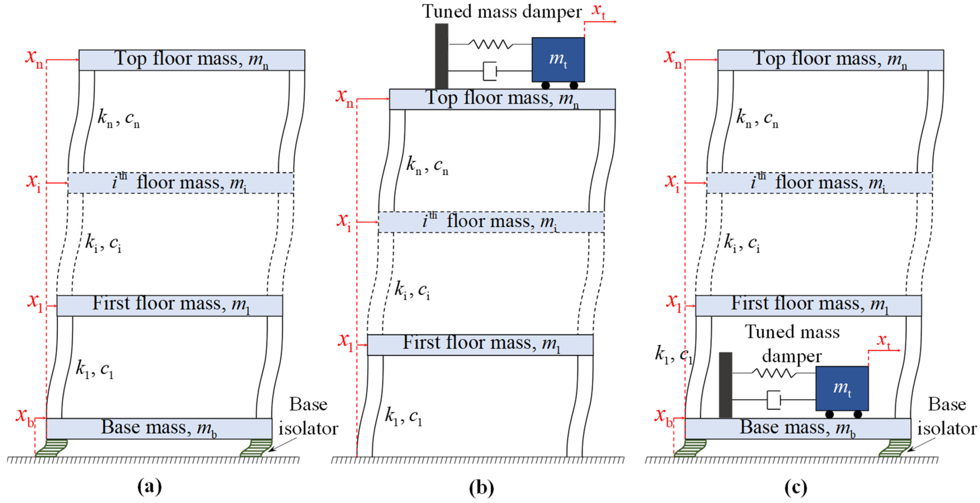
2. Hybrid Vibration Control System Comprising BIS and TMD

2.1. Base Isolation System (BIS)

Figure 1a shows a schematic diagram of a base-isolated building structure. The BISs are vibration control devices that essentially add a flexible layer between the substructure and the superstructure. Due to the high flexibility of the BIS as compared to the primary structure, the time period of the base-isolated structure is lengthened. This phenomenon significantly reduces the acceleration and drift demands on the base-isolated structure as compared to the fixed-base structure, under seismic excitations. In fact, the BISs shift the natural frequency of structure away from the dominant excitation frequencies of the earthquake ground excitations. Therefore, during any event of an earthquake, although the ground underneath the base-isolated structure vibrates, the superstructure remains isolated from the ground vibration. Moreover, the BIS changes the fundamental mode of vibration of the structure, i.e., it is converted from the cantilever mode, where the building experiences significant inter-story drifts and story shear forces, to rigid (isolation) mode, where the response (deformation) is concentrated at the isolation level and the superstructure experiences minimal inter-story drifts and shear forces. Since most of the input energy is dissipated or absorbed by the isolation system itself, the damping characteristics of the isolation system play a significant role in the performance of the BIS. Hence, in some cases providing additional damping mechanisms becomes important in reduction of the excessive displacement response experienced by the base isolators.
The BISs are primarily categorized into three broad groups: the elastomeric isolation systems, the sliding-type isolation systems, and the rolling-type isolation systems. The primary component of the elastomeric isolation systems is rubber, which adds flexibility to the base-isolated structure. In sliding-type isolation systems, the superstructure and substructure are completely decoupled, generally by using steel plates at their interface which could slide against each other. Here, the energy from the seismic excitations is dissipated at the isolation level through the friction between the two steel plates. In rolling-type isolation systems, rollers are inserted between the superstructure and substructure so that the energy dissipation takes place in rolling friction [65,66].
Now, amongst elastomeric isolation systems, SREIs or laminated rubber bearings are most popular, which are constructed by stacking alternate layers of steel shims and rubber layers with two outer steel plates, wherein all the different elements are fixedly attached. The rubber layers are responsible for providing the flexibility to the isolator in the horizontal direction, and the steel shims provide the high vertical stiffness to the SREIs. Moreover, the steel shims divide the rubber pad into layers, which prevent the bulging of the rubber under the large vertical loads from the structure. The external steel plates are utilized to attach the isolators to the superstructure and substructure by bolted connections.
Lead rubber bearings (LRBs) are another type of elastomeric isolation devices, where a cylindrical lead core, centrally located in the vertical direction, is added to the SREIs. The lead core provides initial rigidity to the isolator, which ensures a stiff connection under the weaker seismic excitations, and under stronger excitations, the lead core yields, thus making the isolator flexible in the horizontal direction. The yielding of the lead core also dissipates significant energy, which reduces the bearing displacements under strong earthquake excitations. The recrystallization of the lead core later helps in regaining the bilinear force–deformation properties of the isolator, useful in subsequent earthquake events. In addition to these conventional elastomeric bearings, the FREIs are emerging elastomeric isolation systems, which are lightweight and more flexible in nature. A detailed review of the development and implementation of FREIs is presented in the previous section.
Pure friction isolation devices are the simplest form of sliding-type isolation systems which rely on the sliding between two steel plates attached to the superstructure and substructure. However, pure friction devices are unable to generate sufficient restoring forces to minimize the residual displacements of the superstructure. Therefore, friction pendulum systems were invented wherein a curved surface is utilized for construction of the sliding devices. This curved surface helps the structure to recenter itself after experiencing large sliding displacements, thus avoiding residual displacements of the superstructure. Friction pendulum systems are innovative sliding-based devices that combine both the sliding mechanism of isolators and the concept of pendulum-type response in one device. Further, resilient-friction base isolators are another type of sliding isolators, which are composed of concentric layers of Teflon-coated plates, with a central rubber core. These devices utilize the benefits of both the sliding isolation devices and the elastomeric isolation devices. Shahabi et al. [67] have presented a comprehensive review of the various types of isolation devices based on their working mechanisms. In this study, the UFREIs are utilized for constituting the highly flexible BIS in the hybrid vibration control system.

2.2. Tuned Mass Damper (TMD)

Figure 1b shows a schematic diagram of a structure equipped with a TMD on its top floor. The TMD is a vibration control device that is essentially an additional mass attached to the structure by means of some stiffness and damping devices. The basic working principle of the TMD is to dissipate most of the incoming energy through the vibration of the secondary mass attached to the structure, thus reducing the vibration of the primary structure under dynamic excitations. The main features of a TMD are its tuning ratio, damping ratio, and mass ratio. The tuning ratio of a TMD is defined as the ratio of the natural frequency of the TMD to the natural frequency of the primary structure. It is an important property of the TMD, and it dominates the performance of the TMD under dynamic excitations. Ideally, the TMD is tuned to the fundamental frequency of the structure. It is to be noted that TMDs demonstrate the phenomenon of frequency splitting, i.e., it splits the tuned frequency of the primary structure into two other frequencies around the tuned frequency. This is achieved by addition of the TMD degree-of-freedom to the structure, and it shifts the resonating condition away from the fundamental frequency of the structure. Further, the damping ratio of the TMD has an important role in its functioning. A TMD with no damping results in the reduction of the structural response at the tuned frequency. However, it creates two other frequencies where large vibration response is possible through resonance. Therefore, the damping ratio of the TMD should be chosen optimally such that the trade-off between the performance at the primary structure’s resonance condition and the performance at all other frequencies are appropriately considered. Further, higher damping ratios reduce the stroke length of the TMD mass, which enhances the functionality of the TMD-controlled structure. Mass ratio of the TMD is the ratio of mass of the TMD to the mass of the primary structure. Higher mass ratios of TMD generally result in better control performance up to certain mass ratio levels, after which there is minimal effect of any increase in the TMD mass. Having said that, heavy TMD mass also requires the primary structure to be designed such that it can carry the higher loads induced by the TMD, thus increasing the overall costs. Therefore, the optimization of these design parameters of the TMD are advisable to obtain the best performance of the TMD-controlled structure.
The TMDs are installed in various structures worldwide for mitigation of dynamic loads caused by earthquake or wind excitations [68]. The specific configuration of the TMD depends on the availability of space and resources at the site of interest. Translational TMD is the simplest form of the TMD in which a mass block is connected to the structure by the means of a spring and a damping element. The mass rests on some bearings that allow the free motion of the TMD in the horizontal direction. The bearings should ideally be frictionless, otherwise the effect of the bearing friction needs to be considered in the restoring force exerted by the TMD. Further, pendulum TMDs are one of the most common forms of TMDs, especially implemented in tall structures subjected to wind-imparted loads. In pendulum TMDs, the stiffness is provided through pendulum action on the mass, and the damping is provided through additional damping elements. Pendulum TMDs also have an aesthetic appeal in addition to their response control capabilities. Apart from these basic configurations, TMDs could be installed in various other forms, such as mass resting on rubber pads or a pendulum ring TMD, where the TMD force is transmitted to the primary structure using a shell and stiffener arrangement. A detailed account of the various types of TMDs is provided in several books [69,70]. In the present study, the translation TMD configuration is utilized for reducing the excessive displacements occurring in the base isolation level of the structure.

2.3. Hybrid Vibration Control System

In this study, a hybrid vibration control device is utilized that is composed of a combination of BIS and TMD. Figure 1c shows a schematic diagram of a structure equipped with such a hybrid vibration control system. In this type of hybrid vibration control systems, the advantages of both, the BIS and the TMD, are utilized. As already discussed, BISs are efficient vibration control devices for structures under earthquake excitations; however, excessive displacements could occur at the isolation level of the base-isolated structure under strong earthquakes, which negatively influences the serviceability of the structure (refer to Section 1). Therefore, a TMD is attached to the base mass of the base-isolated structure, and the TMD is tuned to the natural frequency of the base-isolated structure. The TMD reduces the excessive vibration of the structure at the isolator level. Therefore, in the hybrid-controlled structure, the BIS reduces the inter-story drifts and shear forces of the primary structure, and the TMD reduces the excessive displacement at the isolator level, making the structure safer and serviceable. Hybrid vibration control devices are especially necessary to achieve supreme performance levels in the controlled structure under severe dynamic excitations. In this study, the hybrid vibration control system with BIS and TMD is utilized to maintain operational conditions inside hospital buildings during and after strong earthquakes under the MCE scenario. The detailed formulations of the equations of motion of the hybrid-controlled structure are explained in the subsequent section.

3. Modeling of the UFREI-Isolated Hospital Building with TMD

3.1. Modeling of the Dwarka Hospital Building

In the present study, seismic performance of an existing hospital building situated in Dwarka, New Delhi, India, is investigated. The considered building is part of a large health infrastructure project, which has a total site area of 60,000 m2. The hospital consists of seven blocks that are interconnected using separation joints. The actual hospital building is base-isolated using lead rubber bearings (LRBs); however, here the performance of the UFREI-based isolation system is tested for the seismic isolation of one particular ward block of this hospital.
Figure 2 shows the plan of a typical floor of the ward block of the considered hospital building in Dwarka, also mentioning the details of the structural members [23]. Since the current study only deals with one ward block of the hospital, henceforth in this article, this specific building is referred to as the Dwarka Hospital building. The Dwarka Hospital building is an eight-story reinforced concrete (RC) structure with two additional basement stories. The isolators are placed at the ground level, and the required moat width is maintained around the ground floor level for the proper functioning of the base isolators. The first two stories of the superstructure have a height of 4.05 m, the top story has a height of 3.85 m, and all the remaining stories are of 3.9 m height each. The building is almost rectangular in plan with a small setback in one corner. The exact details of the various structural members of the building including their placement in plan are shown in Figure 2. The 28-day characteristic compressive strength of concrete of the beams and slabs is 25 MPa and of the columns and shear walls is 30 MPa.
The interior of the Dwarka Hospital building is partitioned with fly-ash brick walls of 100 mm width, and there is a 75 mm thick floor finish on all the floors except the roof; the floor finish goes up to 200 mm in the roof. The imposed load on each floor of the hospital building is assumed as 2 kN/m2 according to the IS 875 (Part 2): 1987 [71]; 25% of this is considered to be acting on the structure during the event of any earthquake excitation. All this information is utilized in modeling the structure as an idealized multi-degree of freedom (MDOF) shear building model with its masses lumped at each floor level. The governing equations of motion of the MDOF shear building model under seismic excitations are expressed as:
M X ¨ ( t ) + C X ˙ ( t ) + K X ( t ) = M r X ¨ g ( t ) ,
where M , C , and K are the mass, damping, and stiffness matrices of the MDOF system, respectively. Utilizing the various structural and architectural details of the Dwarka Hospital building, the mass and stiffness matrices are evaluated, and the corresponding fundamental time period of the MDOF structure is found to be 0.3714 s in the x-direction. Further, the damping matrix is evaluated by assuming Rayleigh damping, wherein the first two modes of vibration are proportionally damped with a damping ratio of 2%. A structural damping ratio of 2% is considered because the superstructure is not expected to experience any substantial damage such that it could dissipate significant seismic energy during an earthquake event [72]. In Equation (1), X ( t ) , X ˙ ( t ) , and X ¨ ( t ) denote the structural displacement, velocity, and acceleration responses, respectively, with respect to the ground. Further, r = 1 , 1 , , 1 T is the influence coefficient vector and X ¨ g ( t ) represents the seismic ground acceleration applied as a base excitation to the structure.

3.2. Modeling and Design of the UFREI-Based Isolation System

In this study, it is intended to utilize a highly flexible isolation system such that the reduced dynamic response of the Dwarka Hospital building will never be intolerable to the inhabitants, even during the earthquake excitation [73]. In order to achieve response reductions of such magnitude, UFREIs are utilized for the seismic isolation of the Dwarka Hospital building. The nonlinear force–deformation behavior of the UFREIs is modeled by Banerjee and Matsagar [17] utilizing the trilinear hysteretic model (THM). In [17], it is observed that the force–deformation behavior of the UFREI can be represented with the help of three distinct stiffnesses at different levels of horizontal displacements. The behavior of the THM is predominantly governed by the amount of rollover displacement induced in the UFREI with respect to the total side length of the isolator. Figure 3 demonstrates the efficacy of the THM in modeling the nonlinear force–deformation behavior of the UFREI. Also, Figure 3 provides various properties of the normalized THM which could be utilized in the design of an UFREI-based isolation system under any site-specific scenario. From Figure 3, the three linear stiffnesses of the normalized THM are obtained as:
K 1 N = f 01 u 01 , K 2 N = f 02 f 01 u 02 u 01 , and   K 3 N = 0
where f 01 , f 02 , u 01 , and u 02 are the two yield forces and their corresponding yield displacements in the THM. Now, for a certain normalized design displacement of the isolator, D N , the effective stiffness of the isolator based on equivalent linearization is obtained as:
K eff N = f 01 u 01 ,       D N u 01 ; f 01 + K 2 N ( D N u 01 ) D N , u 01 < D N u 02 ; f 02 D N ,         u 02 < D N 0.6 a .
Here, the maximum permissible design displacement of the isolator is restricted to 0.6a, to ensure the stability of the UFREI, where a is the side length of the isolator in the direction of loading. With this, an UFREI of any design isolation period could be modeled with the THM using the effective stiffness given by Equation (3). The systematic step-by-step design procedure of an UFREI using this method is provided by Banerjee and Matsagar [17], thus, not reproduced herein.
In the present study, the Dwarka Hospital building is isolated in the x-direction (refer to Figure 2) with a design isolation time period of 6 s. The reason for adopting such highly flexible isolation time period is to restrict the structural acceleration values under certain limits where the structural vibration is never intolerable to the occupants and acceleration-sensitive secondary systems and equipment. In the design methodology proposed by Banerjee and Matsagar [17], the three input parameters required for the design of the UFREI are the design effective stiffness of the isolator, the design displacement under the site-specific earthquake scenario, and the vertical load on the isolator. Here, the design effective stiffness is evaluated directly from the considered isolation time period, i.e., 6 s. Initially, the design displacement of the isolator is assumed as the maximum displacement of a single-degree-of-freedom (SDOF) system subjected to site-specific earthquake scenarios, where the time period of the SDOF system is the required isolation time period and the damping ratio is assumed to be 18% [17]. Later, the design displacement is updated based on the actual design results of the THM, and thereafter, several iterations of the design process are carried out until the convergence of the design displacement is attained. In the current study, eight site-specific ground motions under the MCE condition are selected, and the final design displacement of the UFREI-based isolation system is computed as 600 mm.
Now, for the considered eight-story hospital building, the total vertical load on the isolation system is obtained as 1.17 × 10 8 N. Literature suggests that the maximum vertical load carrying capacity of the UFREIs are much lesser than other conventional BISs [8,13,19]. Banerjee and Matsagar [17] have considered a vertical pressure of 1.2 MPa on the UFREIs in their proposed design methodology. Therefore, to support the present eight-story hospital building, the required surface area of the UFREIs based on the given vertical load will be impractical. Also, this will result in lower rollover deformations, which hinder the utilization of the flexible behavior of the isolator. Due to these reasons, previously conducted studies have only designed the UFREIs for low-rise structures, where the vertical load is relatively small. In order to cater to this problem and utilize the flexible UFREIs for the Dwarka Hospital building, free sliders—pure friction systems—are provided under each column of the structure to transfer the vertical load from the superstructure to the foundation. Free sliders are commonly manufactured from polytetrafluoroethylene (PTFE)-coated steel plates that can efficiently transfer the vertical load without providing any lateral restoring force to the structure under horizontal displacements [64].
Now, assuming all the aforementioned parameters, the design of the UFREI-based isolation system resulted in a combined isolation system containing 16 UFREIs and 33 free sliders. The specific geometric and material details of a single unit of the designed UFREI is presented in Figure 4 with the help of a schematic diagram of the isolator. Further, Figure 5 shows the exact placement of the various isolators under the ground floor level. It can be observed from Figure 5 that the free sliders are placed directly under each column and under the shear wall to transfer the load of the superstructure to the foundation efficiently. Also, the UFREIs are placed close to the columns leaving 600 mm gap from the free sliders to allow the rollover deformation of the UFREI without any obstruction. This specific arrangement of the UFREIs is selected so as to ensure that the center of the resistive forces from the isolators coincide with the center of stiffness of the structure, thus minimizing any torsional effects on the structure and the isolation system. Since the design vertical pressure on the isolators was 1.2 MPa, the vertical displacement of the actual UFREI corresponding to that pressure was evaluated based on its three-dimensional FE simulation in Abaqus/CAE 2020 (Simulia, Dassault Systems). It was observed that the maximum vertical displacement of the UFREI was close to 13.5 mm; therefore, the depth of the free sliders was designed as 560 mm to maintain sufficient vertical pressure on the UFREIs. The finer details of three-dimensional FE modeling and analysis of the UFREIs are discussed in Banerjee and Matsagar [14,17], thus, not repeated herein. In this study, the focus is primarily on the design and implementation of the UFREI-based isolation system; therefore, the behavior of a single UFREI is not elaborated to keep the content concise.
The detailed design of the UFREI-based isolation system is subsequently implemented in the MDOF shear building model. The equations of motion of the base-isolated Dwarka Hospital building is represented as:
M b X ¨ b ( t ) + C b X ˙ b ( t ) + K b X b ( t ) + F b = M b r b X ¨ g ( t ) ,
where M b , C b , and K b are the mass matrix, damping matrix, and the stiffness matrix of the base-isolated structure, respectively, and given as:
M b = diag ( m b , m 1 , m 2 , , m n ) ,
C b = 0 c 1 0 0 0 0 c 1 + c 2 c 2 0 0 0 c 2 c 2 + c 3 0 0 0 0 0 0 c n ,   and
K b = 0 k 1 0 0 0 0 k 1 + k 2 k 2 0 0 0 k 2 k 2 + k 3 0 0 0 0 0 0 k n .
Here, m i , c i , and k i represent the mass, damping, and stiffness of the ith floor of the MDOF structure; m b denotes the mass of the base floor. The responses of the base mass are defined with respect to the ground, and the responses of all the other floors are defined with respect to the response of the base mass. The vector, F b , represents the restoring force exerted by the UFREIs, which is based on the force–deformation behavior of the UFREIs described in Figure 3. In Equation (4), the restoring force from the isolator acts only in the first two degrees-of-freedom (DOFs), in the opposite phase. Further, the influence vector, r b , contains the value of unity in the first DOF and 1 + X ¨ b / X ¨ g elsewhere, to incorporate change in the frame of reference amongst the different DOFs. Here, the acceleration response of the base mass is denoted as X ¨ b . Utilizing this formulation, the response of the base-isolated structure is evaluated considering the THM for representing the force–deformation behavior of the UFREI.

3.3. Modeling and Design of the Tuned Mass Damper

The UFREI-based isolation system for the Dwarka Hospital building is designed for an isolation time period of 6 s; thus, based on the MCE scenario, its design displacement is obtained as 600 mm, which is significantly high. Such large displacements at the isolator level will be difficult to accommodate in real-life field conditions due to various practical challenges associated with it (refer to Section 1). Therefore, in the present study, the displacement response at the base isolation level of the structure is intended to be reduced by incorporating a TMD at the base floor of the isolated building. Hence, the mass ratio, tuning ratio, and damping ratio of the TMD needs to be designed for this specific base-isolated structure. Typically, it is observed that the performance of the TMD improves with the increase in its mass ratio. However, it is also not practically feasible to install excessively large masses at any particular location in the structure. Therefore, a TMD mass ratio of 10% is considered in the current study based on the installation practicality of the designed TMD. The TMD is designed to be perfectly tuned to the second stiffness of the UFREI-based isolation system (refer Figure 3 for K2N), i.e., the TMD time period is considered to be 5.673 s. This specific tuning frequency is considered because the response of the base-isolated structure is dominated by the frequency of the second stiffness of the THM. These parameters of the TMD have been decided based on previous scientific evidence on the improved performance of the TMDs [32,74]. It was found that the reductions in the base displacements of the structure are substantial with a TMD damping ratio of 10%. Also, slightly high damping ratio ensures lesser stroke length requirement of the TMD, which is important for its real-life implementation. Therefore, the TMD is equipped with a damper having damping ratio of 10%. With these parameters of the designed TMD, the maximum stroke length of the TMD under the considered site-specific ground motions is obtained as 1.235 m, which can be accommodated without posing any severe practical challenges. Therefore, the TMD is placed at the ground floor of the isolated Dwarka Hospital building as shown in Figure 6. As observed from Figure 6, the total mass of the TMD based on 10% mass ratio is divided into six blocks, otherwise a single block of such large mass would be difficult to install within the available story height. Therefore, the designed TMD is divided into six TMDs with identical properties, as shown in Figure 6. All the TMDs have available stroke lengths of 1.25 m, which is greater than their required stroke length. The reason for selecting these specific locations for the installation of the TMDs is to ensure that the center of the resistive forces from the TMDs act close to the center of stiffness of the structure. Since the TMDs are installed at the ground floor, which is designed to have large free spaces for the movement of the occupants, the space occupied by the TMD would not cause much hindrance to the functionality of the structure. Further, the large walls of the TMD mass block could be utilized to display important announcements as commonly observed in reception areas of hospital buildings. These considerations emphasize the viability of installation of the TMD to control the large base displacement of the isolated structure. The performance of the designed TMD in actual response reduction is discussed in the subsequent section.
Now, the specified design of the TMD is incorporated in the MDOF shear building model of the isolated Dwarka Hospital building by addition of a single DOF, which comprises the total TMD mass of the six TMDs installed. This is possible because all the TMDs are identical; thus, their individual responses are equal to the response of the single combined TMD. The equations of motion of the hybrid-controlled structure with the UFREI and the TMD can be represented as:
M h X ¨ h ( t ) + C h X ˙ h ( t ) + K h X h ( t ) + F h = M h r h X ¨ g ( t ) . ,
where M h , C h , and K h are the mass matrix, damping matrix, and the stiffness matrix, respectively, of the controlled structure with both UFREI and TMD and are given as:
M h = diag ( m b , m 1 , m 2 , , m n , m t ) ,
C h = 0 c 1 0 0 0 c t 0 c 1 + c 2 c 2 0 0 0 0 c 2 c 2 + c 3 0 0 0 0 0 0 0 0 c n 0 0 0 0 0 0 c t ,   and
K h = 0 k 1 0 0 0 k t 0 k 1 + k 2 k 2 0 0 0 0 k 2 k 2 + k 3 0 0 0 0 0 0 0 0 k n 0 0 0 0 0 0 k t .
Here, m t , c t , and k t denote the mass, damping coefficient, and the stiffness of the TMD, respectively. It should be noted here that the TMD properties in Equations (9)–(11) are the combined properties of all the TMDs, i.e., the summation of the individual TMD properties shown in Figure 6. Here, F h and r h simply have an additional DOF with the same values as the rest of the superstructure. Ultimately, Equation (8) is solved to evaluate the site-specific seismic response of the controlled structure with UFREI and TMD.

4. Numerical Study

The performance of the Dwarka Hospital building equipped with the UFREI-based isolation system and the TMD is now evaluated under a set of site-specific earthquake ground motions. Initially, eight recorded earthquake ground motions are selected with a wide variety of properties, including both near-fault and far-fault ground motions. The eight selected earthquake records are then scaled according to the site-specific earthquake scenario in New Delhi, India, considering the MCE condition. The target response spectrum is obtained from IS 1893 (Part 1): 2016 [75] for medium-type soil. The importance factor for the hospital building is considered as 1.5, and the response reduction factor is assumed to be 1 because the superstructure is not intended to experience any damage due to the earthquake excitation. Note that, as a conservative measure, ductile detailing of the RC structure is highly recommended as a best construction practice. Hence, some structural designers tend to assume a marginally higher response reduction factor, of say 1.1.
The design basis earthquake (DBE) conditioned response spectrum is multiplied by a factor of two to obtain the target spectrum for the MCE scenario. The response spectra of the selected earthquake records are scaled to match with the target spectrum using the software, SeismoMatch (Version 2022, Release 1) [76]. The details of the eight considered ground acceleration records are presented in Table 1. Figure 7 shows the (a) acceleration and (b) displacement response spectra of the scaled ground motion records according to the site-specific earthquake scenario. It is observed from Figure 7 that the scaled earthquake ground motions have closely matched with the target spectrum, thus ensuring the site-specific earthquake condition.
Now, the controlled Dwarka Hospital building installed with the UFREI and the TMD is subjected to the selected site-specific earthquake ground motions for its dynamic response evaluation. The response of all the various types of structural models, i.e., the uncontrolled structure, UFREI-isolated structure, and the hybrid-controlled structure are estimated by conducting nonlinear time-history analyses. The 4th-order Runge–Kutta method is used for the step-by-step integration of the equations of motion of the various structural systems. Figure 8 shows the absolute top-floor acceleration response of (a) the uncontrolled structure, (b) the UFREI-isolated structure, and (c) the hybrid-controlled structure. The time-history responses shown in Figure 8 are truncated for better clarity in the critical regions, i.e., the regions with higher accelerations. It is observed from Figure 8 that the acceleration response of the UFREI-isolated Dwarka Hospital building is almost negligible as compared to the uncontrolled (conventional fixed-base) building’s response. Under all the earthquake excitations, the peak top floor acceleration response has reduced by about 95% due to the provision of highly flexible UFREI-based isolation system. This is important because such flexible UFREI-based isolation system has been designed intentionally such that the inhabitants of the hospital building are not required to evacuate the building during the earthquake event. Thereby, the intent of seismic performance is operation level (continued functionality) than immediate occupancy level. Typically, ensuring such stringent vibration limits are not common in the seismic design of buildings; therefore, the exact limiting values of the acceleration response of a structure are not clearly defined under such scenarios. However, a few studies exist where the peak acceleration limits of structures due to wind-imparted loads are defined for various functional requirements [73,77]. Essentially, the various performance levels of structures under winds are demarcated as ‘not perceptible’, ‘perceptible’, ‘annoying’, ‘very annoying’, and ‘intolerable’ [73], on the basis of peak acceleration response of the structure. Since earthquake hazards are of much lower duration as compared to typical wind hazards, the objective here is to ensure at least structural accelerations under the ‘intolerable’ limit, i.e., below 15% of gravitational acceleration, g [73], which will in turn ensure that the inhabitants will never panic and be required to exit the building during the earthquake event. Moreover, the reduced story drifts experienced in such design ensure protection of the displacement-sensitive secondary systems, such as piping and supply lines (refer to Figure 10 for inter-story drift responses).
As seen from Figure 8, the peak acceleration responses of the UFREI-isolated structure and the UFREI-isolated structure with TMD are both substantially below the stated limiting value, which justifies the design of such flexible isolation systems. Figure 8 also reveals that the response of the UFREI-isolated structure and the hybrid (UFREI and TMD)-controlled structure are comparable to each other with minimal visible differences. This implies that the addition of the TMD to the isolated structure does not increase the acceleration response of the structure. In fact, it is seen from Figure 9 that the acceleration response of the structure actually decreases under most of the earthquakes due to the addition of the TMD to the UFREI-isolated structure. Such low levels of acceleration also ensure continued functionality of acceleration-sensitive machines and equipment contained within the building, which are common commodities in hospital buildings.
Figure 9 presents the peak acceleration responses of all the floors of the eight-story hospital building, when the building is (a) uncontrolled, (b) UFREI-isolated, and (c) hybrid-controlled using UFREI and TMD. It is observed that the peak acceleration response of the uncontrolled building at each floor has reduced significantly due to both the UFREI-based isolation system and the hybrid (UFREI and TMD) control system. Although the peak acceleration responses of all the floors have minimal variations using TMD with base isolator when compared to using only the base isolator, the hybrid (UFREI and TMD) control system has been effective in further reducing the responses of the base-isolated structure slightly under all the earthquakes, except EQ2 and EQ4 (Figure 9). This implies that apart from reducing the base displacement of the isolated Dwarka Hospital building, the TMD could also minimally reduce the acceleration response of the isolated superstructure, which is an added advantage in the installation of the TMD.
The performance of structures under seismic excitations are often measured with the help of peak inter-story drifts experienced by the structure. Therefore, Figure 10 shows the peak inter-story drift response of the (a) uncontrolled, (b) UFREI-isolated, and (c) hybrid (UFREI + TMD)-controlled Dwarka Hospital building, when subjected to the various site-specific earthquake excitations. Interestingly, it is observed that due to adoption of such stringent structural acceleration limit for the design of the BIS, the limit for serviceable condition based on the peak inter-story drift has automatically been taken into account. According to Galambos and Ellingwood [78], the maximum allowable inter-story drift for serviceable conditions in buildings is 0.1%. It is seen from Figure 10 that the controlled peak structural inter-story drifts are much lesser than 0.1% using both only the UFREI-based isolation system and the UFREI-based isolation system with TMD. Here too, differences between the response of the UFREI-isolated structure and the hybrid-controlled structure are rarely visible. Having said that, the performance of the hybrid (UFREI and TMD) control system is slightly better than that of the isolation system alone in most of the cases. Also, the reductions in the peak base shear of the Dwarka Hospital building are observed to be higher than 90% under all the site-specific earthquakes (results not included here) using both systems, (a) UFREI-based isolation system and (b) hybrid (UFREI and TMD) control system.
It is now established that the use of the TMD with the UFREI-based isolation system has not diminished the control performance of the isolation system by any means, rather it results in slightly improved superstructure response reductions. Nevertheless, the major necessity of the additional TMD in the UFREI-isolated structure is revealed through Figure 11. Figure 11 shows the bearing displacement time-history response of the (a) UFREI-isolated and (b) hybrid-controlled Dwarka Hospital buildings. It is observed from Figure 11 that the peak displacement of the UFREI-isolated structure at the base isolation level is reduced by 9% to by 27% due to the addition of the TMD at the base floor of the Dwarka Hospital building. Fascinatingly, the peak bearing displacement of the isolator is reduced from 598 mm to 438 mm, which implies that the TMD is effective in reducing the design displacement of the isolator by 160 mm without inducing a higher acceleration demand on the superstructure. Therefore, the addition of the TMD to the UFREI-isolated structure could effectively reduce the design displacement of the base isolation system by 27%. A reduction of such magnitude in the design bearing displacement is of prime importance as it will directly influence the required moat width around the base-isolated structure and also have a positive effect on the other serviceability conditions of the hospital building.
The results presented in this article are obtained considering the TMD to be tuned to the second stiffness of the isolation system since it dominates the seismic response of the UFREI-isolated structure. Having said that, in case the TMD is tuned to the effective stiffness of the UFREI-based isolation system, similar reductions in the bearing displacements of the isolated hospital building are observed (results not included here). The reason for this behavior is that the second stiffness of the isolator is quite close to the effective stiffness of the isolation system, as per expectation. Nevertheless, the reduction in the design displacement of the isolation system is more when the TMD is tuned to the second stiffness of the isolation system.
Figure 12 shows the force–deformation behavior of the UFREI-based isolation system under the various site-specific earthquakes, when the Dwarka Hospital building is (a) only base-isolated and (b) equipped with BIS and TMD. It is observed that the designed isolation system is effective in achieving the required structural performance because the UFREI-isolated Dwarka Hospital building has shown an effective isolation time period in the range of 4.4 s to 5.9 s under the various seismic excitations. Nevertheless, the UFREI-based isolation system did not experience large displacements under all the considered earthquakes, thus displaying a bilinear force–deformation behavior wherever the isolator displacement did not exceed the second yield displacement of the designed isolation system. Further, when the TMD is added to the UFREI-isolated Dwarka Hospital building, the isolator displacements have reduced significantly, which is also reflected in the force–deformation behavior of the UFREI-based isolations system. The modified effective time periods of the controlled structure have been obtained in the range of 4.22 s to 4.80 s under the various earthquakes, due to the addition of the TMD. Having said that, the reduction in the effective time period of the isolated structure does not translate into its structural dynamic response as observed from Figure 8, Figure 9 and Figure 10. This summarizes the effectiveness of the hybrid vibration control system using the UFREI-based isolation system and the TMD. Although the restoring force exerted by the flexible UFREI-based isolation system is lesser as compared to conventional isolation systems, it is found that the maximum residual displacement in the UFREI-isolated structure is within 5 mm (i.e., 0.83% of the maximum displacement, 598 mm), and the hybrid-controlled structure is within 19 mm (i.e., 4.35% of the maximum displacement, 438 mm), under the various site-specific earthquake excitations. Therefore, it could be concluded that the restoring forces exerted by the isolation system is enough to avoid any significant residual displacements in the base-isolated or the hybrid-controlled structure.

5. Conclusions

In this article, the design of a new hybrid vibration control system, comprising a UFREI-based flexible isolation system and TMD, is investigated for the response reduction of an existing hospital building. For ensuring operational condition in the base-isolated hospital building under strong earthquakes, its peak structural acceleration responses are restricted to certain limiting value such that the acceleration of the structure will always remain tolerable to the building inhabitants even during the earthquakes, which implies that the occupants will never panic and vacate the structure even during the earthquake. To incorporate such stringent performance criterion, a flexible UFREI-based isolation system is designed for the Dwarka Hospital building with an effective isolation period of 6 s. The design displacement of the UFREI-based isolation system is found to be 600 mm under the site-specific earthquake excitations in the MCE condition. Therefore, a TMD is installed at the base floor of the isolated structure to reduce the bearing displacement of the UFREI-isolated hospital building. The complete design of the hybrid (UFREI and TMD) control system for the Dwarka Hospital building is elaborated with special emphasis on the practical implementation of the proposed control system. Further, nonlinear time-history analysis is undertaken to obtain the response of the hybrid-controlled Dwarka Hospital building under an ensemble of site-specific earthquake ground motions. The major conclusions drawn from the research conducted are as follows.
  • It is possible to design highly flexible UFREI-based isolation systems for new and existing structures under certain site-specific conditions, with the help of the THM for representing its force–deformation behavior. For comparably taller structures, i.e., structures which exert larger vertical load on the isolation system, free sliders could be utilized to transfer the load from the superstructure to the substructure, where the UFREIs would only provide the restoring force to the structure.
  • A feasible solution for the installation of the TMD in the base floor of the hospital building is presented herein. In order to accommodate such large TMD mass in the UFREI-isolated Dwarka Hospital building, the single TMD mass is divided into six identical mass blocks and each of them are attached to the structure ensuring the same tuned frequency in all the TMDs. Also, the maximum stroke length required for the designed TMD system in the MCE scenario was found to be 1.235 m, which could be easily accommodated on site.
  • The design isolation time period of the UFREI-based isolation system is considered to be 6 s. This resulted in more than 90% reduction in the peak structural acceleration responses, peak base shear induced in the superstructure, and peak inter-story drifts in the superstructure, when the structure is base-isolated as compared to the uncontrolled structural responses. Reductions of this magnitude ensured that the structural vibration is always within the tolerable limits for the inhabitants, even during the earthquake excitation. This is extremely important to achieve operational condition in lifeline structures such as hospitals during the earthquake hazard.
  • The addition of the TMD to the UFREI-isolated Dwarka Hospital building has successfully reduced the peak bearing displacements of the isolated structure by 9% to by 27%, under the various site-specific earthquakes. The maximum displacement of the structure at the isolation level was reduced to 438 mm from 598 mm. This is highly beneficial as it avoids the various practical and serviceability issues involved with large bearing displacements of flexible isolation systems.
  • Importantly, the large reductions in the bearing displacement of the UFREI-isolated Dwarka Hospital building using the hybrid (UFREI and TMD) control systems did not compromise with the performance of the base-isolated structure. The structural responses of the hybrid (UFREI and TMD)-controlled Dwarka Hospital building are comparable to that of the UFREI-isolated building. In fact, the control performance of the hybrid-controlled building is even better than the UFREI-isolated building under most of the site-specific seismic excitations.

Author Contributions

Conceptualization, V.M.; Methodology, S.B. and V.M.; Software, S.B.; Validation, S.B.; Formal analysis, S.B.; Investigation, S.B. and V.M.; Resources, V.M.; Writing—original draft, S.B.; Writing—review & editing, S.B. and V.M.; Visualization, S.B. and V.M.; Supervision, V.M.; Project administration, V.M.; Funding acquisition, V.M. All authors have read and agreed to the published version of the manuscript.

Funding

This research was funded by Coalition for Disaster Resilient Infrastructure: Fellowship Application Number 210117472. Nevertheless, the opinions expressed and findings reported in this document are those of the authors only and not of the funding agency.

Data Availability Statement

Any additional data supporting the findings of this study are available from the corresponding author upon reasonable request.

Acknowledgments

The authors gratefully acknowledge the Prime Minister’s Research Fellows (PMRF) Scheme of Government of India and the Amiya Basu Research Award in Civil Engineering for supporting this doctoral research study in Indian Institute of Technology (IIT) Delhi.

Conflicts of Interest

The authors declare no conflict of interest.

References

  1. Kelly, J.M. Aseismic base isolation: Review and bibliography. Soil Dyn. Earthq. Eng. 1986, 5, 202–216. [Google Scholar] [CrossRef]
  2. Naeim, F.; Kelly, J.M. Design of Seismic Isolated Structures: From Theory to Practice; John Wiley and Sons, Inc.: Hoboken, NJ, USA, 1999. [Google Scholar]
  3. Matsagar, V.A.; Jangid, R.S. Base isolation for seismic retrofitting of structures. Pract. Period. Struct. Des. Constr. 2008, 13, 175–185. [Google Scholar] [CrossRef]
  4. Kelly, J.M. Analysis of fiber-reinforced elastomeric isolators. J. Seismol. Earth-Quake Eng. 1999, 2, 19–34. [Google Scholar]
  5. Tsai, H.-C.; Kelly, J.M. Stiffness analysis of fiber-reinforced rectangular seismic isolators. J. Eng. Mech. 2002, 128, 462–470. [Google Scholar] [CrossRef]
  6. Toopchi-Nezhad, H.; Tait, M.J.; Drysdale, R.G. Bonded versus unbonded strip fiber reinforced elastomeric isolators: Finite element analysis. Compos. Struct. 2011, 93, 850–859. [Google Scholar] [CrossRef]
  7. Osgooei, P.M.; Tait, M.J.; Konstantinidis, D. Finite element analysis of unbonded square fiber-reinforced elastomeric isolators (FREIs) under lateral loading in different directions. Compos. Struct. 2014, 113, 164–173. [Google Scholar] [CrossRef]
  8. Das, A.; Dutta, A.; Deb, S.K. Performance of fiber-reinforced elastomeric base isolators under cyclic excitation. Struct. Control Health Monit. 2015, 22, 197–220. [Google Scholar] [CrossRef]
  9. Van Engelen, N.C.; Tait, M.J.; Konstantinidis, D. Model of the shear behavior of unbonded fiber-reinforced elastomeric isolators. J. Struct. Eng. 2015, 141, 4014169. [Google Scholar] [CrossRef]
  10. Van Engelen, N.C.; Tait, M.J.; Konstantinidis, D. Development of design code oriented formulas for elastomeric bearings including bulk compressibility and reinforcement extensibility. J. Eng. Mech. 2016, 142, 4016024. [Google Scholar] [CrossRef]
  11. Ehsani, B.; Toopchi-Nezhad, H. Systematic design of unbonded fiber reinforced elastomeric isolators. Eng. Struct. 2017, 132, 383–398. [Google Scholar] [CrossRef]
  12. Ngo, T.V.; Dutta, A.; Deb, S.K. Evaluation of horizontal stiffness of fibre-reinforced elastomeric isolators. Earthq. Eng. Struct. Dyn. 2017, 46, 1747–1767. [Google Scholar] [CrossRef]
  13. Ngo, T.V.; Deb, S.K.; Dutta, A. Effect of horizontal loading direction on performance of prototype square unbonded fibre reinforced elastomeric isolator. Struct. Control Health Monit. 2018, 25, e2112. [Google Scholar] [CrossRef]
  14. Banerjee, S.; Matsagar, V.A. Dynamic behavior of unbonded fiber-reinforced elastomeric isolators. In Proceedings of the 12th National Conference in Earthquake Engineering, Earthquake Engineering Research Institute (EERI), Salt Lake City, UT, USA, 27 June–1 July 2022 ; Available online: https://www.eeri.org/what-we-offer/digital-library/?lid=12723 (accessed on 3 July 2023).
  15. Cilento, F.; Losanno, D.; Piga, L. An experimental study on a novel reclaimed rubber compound for fiber-reinforced seismic isolators. Structures 2022, 45, 9–22. [Google Scholar] [CrossRef]
  16. De Domenico, D.; Losanno, D.; Vaiana, N. Experimental tests and numerical modeling of full-scale unbonded fiber reinforced elastomeric isolators (UFREIs) under bidirectional excitation. Eng. Struct. 2023, 274, 115118. [Google Scholar] [CrossRef]
  17. Banerjee, S.; Matsagar, V.A. A trilinear hysteretic model and design procedure for unbonded fiber-reinforced elastomeric isolators. J. Struct. Eng. ASCE, 2023; under review. [Google Scholar]
  18. Van Engelen, N.C. Fiber-reinforced elastomeric isolators: A review. Soil Dyn. Earthq. Eng. 2019, 125, 105621. [Google Scholar] [CrossRef]
  19. Toopchi-Nezhad, H.; Tait, M.J.; Drysdale, R.G. Lateral response evaluation of fiber-reinforced neoprene seismic isolators utilized in an unbonded application. J. Struct. Eng. 2008, 134, 1627–1637. [Google Scholar] [CrossRef]
  20. Das, A.; Deb, S.K.; Dutta, A. Shake table testing of un-reinforced brick masonry building test model isolated by U-FREI. Earthq. Eng. Struct. Dyn. 2016, 45, 253–272. [Google Scholar] [CrossRef]
  21. Thuyet, V.N.; Deb, S.K.; Dutta, A. Mitigation of seismic vulnerability of prototype low-rise masonry building using U-FREIs. J. Perform. Constr. Facil. 2018, 32, 4017136. [Google Scholar] [CrossRef]
  22. Ariga, T.; Kanno, Y.; Takewaki, I. Resonant behaviour of base-isolated high-rise buildings under long-period ground motions. Struct. Des. Tall Spec. Build. 2006, 15, 325–338. [Google Scholar] [CrossRef]
  23. Banerjee, S.; Matsagar, V.A. Earthquake response control of hospital building using unbonded fibre-reinforced elastomeric isolators” in Coalition for Disaster Resilient Infrastructure (CDRI) 2022 conference proceedings. Sustain. Resilient Infrastruct. 2023, 8, 85–92. [Google Scholar] [CrossRef]
  24. Jangid, R.S.; Kelly, J.M. Base isolation for near-fault motions. Earthq. Eng. Struct. Dyn. 2001, 30, 691–707. [Google Scholar] [CrossRef]
  25. Engle, T.; Mahmoud, H.; Chulahwat, A. Hybrid tuned mass damper and isolation floor slab system optimized for vibration control. J. Earthq. Eng. 2015, 19, 1197–1221. [Google Scholar] [CrossRef]
  26. Zelleke, D.H.; Elias, S.; Matsagar, V.A.; Jain, A.K. Supplemental dampers in base-isolated buildings to mitigate large isolator displacement under earthquake excitations. Bull. N. Z. Soc. Earthq. Eng. 2015, 48, 100–117. [Google Scholar] [CrossRef] [Green Version]
  27. Rayegani, A.; Nouri, G. Application of smart dampers for prevention of seismic pounding in isolated structures subjected to near-fault earthquakes. J. Earthq. Eng. 2020, 26, 4069–4084. [Google Scholar] [CrossRef]
  28. Rayegani, A.; Nouri, G. Seismic collapse probability and life cycle cost assessment of isolated structures subjected to pounding with smart hybrid isolation system using a modified fuzzy based controller. Structures 2022, 44, 30–41. [Google Scholar] [CrossRef]
  29. Matsagar, V.A.; Jangid, R. Seismic response of base-isolated structures during impact with adjacent structures. Eng. Struct. 2003, 25, 1311–1323. [Google Scholar] [CrossRef]
  30. Panda, J.; Chakraborty, S.; Ray-Chaudhuri, S. Development and performance evaluation of a robust suboptimal H∞-based proportional-integral controller-observer system with target tracking for better control of seismic responses. Struct. Control Health Monit. 2022, 29, e3084. [Google Scholar] [CrossRef]
  31. Rahmani, B.; Ziaiefar, A.; Hashemi, S. Output feedback-based adaptive fuzzy sliding mode control for seismic response reduction of base-isolated buildings. ISA Trans. 2022, 126, 94–108. [Google Scholar] [CrossRef] [PubMed]
  32. Elias, S.; Matsagar, V. Research developments in vibration control of structures using passive tuned mass dampers. Annu. Rev. Control 2017, 44, 129–156. [Google Scholar] [CrossRef]
  33. Warburton, G.B. Optimum absorber parameters for various combinations of response and excitation parameters. Earthq. Eng. Struct. Dyn. 1982, 10, 381–401. [Google Scholar] [CrossRef]
  34. Tsai, H.-C.; Lin, G.-C. Optimum tuned-mass dampers for minimizing steady-state response of support-excited and damped systems. Earthq. Eng. Struct. Dyn. 1993, 22, 957–973. [Google Scholar] [CrossRef]
  35. Sadek, F.; Mohraz, B.; Taylor, A.W.; Chung, R.M. A method of estimating the parameters of tuned mass dampers for seismic applications. Earthq. Eng. Struct. Dyn. 1997, 26, 617–635. [Google Scholar] [CrossRef]
  36. Hoang, N.; Fujino, Y.; Warnitchai, P. Optimal tuned mass damper for seismic applications and practical design formulas. Eng. Struct. 2008, 30, 707–715. [Google Scholar] [CrossRef]
  37. Elias, S.; Matsagar, V. Optimum tuned mass damper for wind and earthquake response control of high-rise building. Adv. Struct. Eng. 2015, 2, 1475–1487. [Google Scholar] [CrossRef]
  38. Bekdaş, G.; Nigdeli, S.M.; Yang, X.-S. A novel bat algorithm based optimum tuning of mass dampers for improving the seismic safety of structures. Eng. Struct. 2018, 159, 89–98. [Google Scholar] [CrossRef]
  39. Banerjee, S.; Ghosh, A. Optimal design of nonlinear TMD with Bingham-type damping for base-excited structures. J. Struct. Integr. Maint. 2020, 5, 211–222. [Google Scholar] [CrossRef]
  40. Banerjee, S.; Ghosh, A. Optimal design of tuned mass damper for base-excited structures. IOP Conf. Ser. Mater. Sci. Eng. 2020, 936, 12016. [Google Scholar] [CrossRef]
  41. Banerjee, S.; Ghosh, A.D.; Matsagar, V.A. Optimum design of nonlinear tuned mass damper for dynamic response control under earthquake and wind excitations. Struct. Control Health Monit. 2022, 29, e2960. [Google Scholar] [CrossRef]
  42. Sladek, J.R.; Klingner, R.E. Effect of tuned-mass dampers on seismic response. J. Struct. Eng. 1983, 109, 2004–2009. [Google Scholar] [CrossRef]
  43. Kwok, K.C.S.; Samali, B. Performance of tuned mass dampers under wind loads. Eng. Struct. 1995, 17, 655–667. [Google Scholar] [CrossRef]
  44. Murudi, M.M.; Mane, S.M. Seismic effectiveness of tuned mass damper (TMD) for different ground motion parameters. In Proceedings of the 13th World Conference on Earthquake Engineering, Vancouver, BC, Canada, 1–4 August 2004. [Google Scholar]
  45. Elias, S.; Matsagar, V. Wind response control of tall buildings with a tuned mass damper. J. Build. Eng. 2018, 15, 51–60. [Google Scholar] [CrossRef]
  46. Elias, S.; Matsagar, V.; Datta, T.K. Along-wind response control of chimneys with distributed multiple tuned mass dampers. Struct. Control Health Monit. 2019, 26, e2275. [Google Scholar] [CrossRef] [Green Version]
  47. Yang, J.N.; Danielians, A.; Liu, S.C.; Yang, M.J.N.; Member, A.S. Aseismic Hybrid Control Systems for Building Structures. J. Eng. Mech. 1991, 117, 836–853. [Google Scholar] [CrossRef]
  48. Tsai, H.-C. The effect of tuned-mass dampers on the seismic response of base-isolated structures. Int. J. Solids Struct. 1995, 32, 1195–1210. [Google Scholar] [CrossRef]
  49. Xiang, P.; Nishitani, A. Optimum design for more effective tuned mass damper system and its application to base-isolated buildings. Struct. Control Health Monit. 2014, 21, 98–114. [Google Scholar] [CrossRef]
  50. Naderpour, H.; Naji, N.; Burkacki, D.; Jankowski, R. Seismic response of high-rise buildings equipped with base isolation and non-traditional tuned mass dampers. Appl. Sci. 2019, 9, 1201. [Google Scholar] [CrossRef] [Green Version]
  51. Hashimoto, T.; Fujita, K.; Tsuji, M.; Takewaki, I. Innovative base-isolated building with large mass-ratio TMD at basement for greater earthquake resilience. Future Cities Environ. 2015, 1, 1–19. [Google Scholar] [CrossRef]
  52. De Domenico, D.; Ricciardi, G. Earthquake-resilient design of base isolated buildings with TMD at basement: Application to a case study. Soil Dyn. Earthq. Eng. 2018, 113, 503–521. [Google Scholar] [CrossRef]
  53. Stanikzai, M.H.; Elias, S.; Matsagar, V.A.; Jain, A.K. Seismic response control of base-isolated buildings using multiple tuned mass dampers. Struct. Des. Tall Spec. Build. 2019, 28, e1576. [Google Scholar] [CrossRef]
  54. Stanikzai, M.H.; Elias, S.; Matsagar, V.A.; Jain, A.K. Seismic response control of base-isolated buildings using tuned mass damper. Aust. J. Struct. Eng. 2020, 21, 310–321. [Google Scholar] [CrossRef]
  55. Morales, C.A. A new approach to inertial damper design to control base displacement in isolated buildings. J. Vib. Control 2021, 28, 3539–3549. [Google Scholar] [CrossRef]
  56. De Domenico, D.; Ricciardi, G. An enhanced base isolation system equipped with optimal tuned mass damper interter (TMDI). Earthq. Eng. Struct. Dyn. 2018, 47, 1169–1192. [Google Scholar] [CrossRef]
  57. Jangid, R.S. Optimum tuned inerter damper for base-isolated structures. J. Vib. Eng. Technol. 2021, 9, 1483–1497. [Google Scholar] [CrossRef]
  58. Nyangi, P.; Ye, K. Optimal design of dual isolated structure with supplemental tuned inerter damper based on performance requirements. Soil Dyn. Earthq. Eng. 2021, 149, 106830. [Google Scholar] [CrossRef]
  59. Pietrosanti, D.; De Angelis, M.; Giaralis, A. Experimental seismic performance assessment and numerical modelling of nonlinear inerter vibration absorber (IVA)-equipped base isolated structures tested on shaking table. Earthq. Eng. Struct. Dyn. 2021, 50, 2732–2753. [Google Scholar] [CrossRef]
  60. Huang, X.; Hu, Z.; Liu, Y.; Nie, L. Study on seismic performance of TID-LRB hybrid control system under multi-level earthquakes. Buildings 2022, 12, 1465. [Google Scholar] [CrossRef]
  61. Zelleke, D.H.; Matsagar, V.A. Hybrid control of smart base-isolated structures under multi-hazard scenarios. In Proceedings of the 7th European Conference on Structural Control, Warsaw, Poland, 10–13 July 2022. [Google Scholar]
  62. Stanikzai, M.H.; Elias, S.; Chae, Y. Recent advances in hybrid vibration-control systems. Pract. Period. Struct. Des. Constr. 2022, 27, 3122003. [Google Scholar] [CrossRef]
  63. Ferraioli, M.; Avossa, A.M. Base isolation seismic retrofit of a hospital building in Italy. J. Civ. Eng. Arch. 2012, 6, 308. [Google Scholar] [CrossRef] [Green Version]
  64. Ferraioli, M.; Mandara, A. Base isolation for seismic retrofitting of a multiple building structure: Design, construction, and assessment. Math. Probl. Eng. 2017, 2017, 4645834. [Google Scholar] [CrossRef] [Green Version]
  65. Rawat, A.; Ummer, N.; Matsagar, V. Performance of bi-directional elliptical rolling rods for base isolation of buildings under near-fault earthquakes. Adv. Struct. Eng. 2018, 21, 675–693. [Google Scholar] [CrossRef]
  66. Rawat, A.; Matsagar, V. Seismic analysis of liquid storage tank using oblate spheroid base isolation system based on rolling friction. Int. J. Non-Linear Mech. 2022, 147, 104186. [Google Scholar] [CrossRef]
  67. Shahabi, A.B.; Ahari, G.Z.; Barghian, M. Base isolation systems—A state of the art review according to their mechanism. J. Rehabil. Civ. Eng. 2020, 8, 37–61. [Google Scholar] [CrossRef]
  68. Soong, T.T.; Dargush, G.F. Passive Energy Dissipation Systems in Structural Engineering; John Wiley and Sons, Inc.: Hoboken, NJ, USA, 1997. [Google Scholar]
  69. Li, A. Vibration Control for Building Structures: Theory and Applications; Springer International Publishing: Berlin/Heidelberg, Germany, 2020. [Google Scholar]
  70. Madhekar, S.; Matsagar, V. Passive Vibration Control of Structures; CRC Press: Boca Raton, FL, USA, 2022. [Google Scholar] [CrossRef]
  71. IS 875 (Part 2): 1987; Design Loads (Other Than Earthquake) for Buildings and Structures—Code of Practice: Part 2 Imposed Loads. Bureau of Indian Standards: New Delhi, India, 1987.
  72. Chopra, A.K. Dynamics of Structures: Theory and Applications to Earthquake Engineering; Prentice Hall of India: New Delhi, India, 2006. [Google Scholar]
  73. Griffis, L.G. Serviceability Limit States under Wind Load; American Institute of Steel Construction: Chicago, IL, USA, 1993. [Google Scholar]
  74. Jangid, R.S. Optimum multiple tuned mass dampers for base-excited undamped system. Earthq. Eng. Struct. Dyn. 1999, 28, 1041–1049. [Google Scholar] [CrossRef]
  75. IS 1893 (Part 1): 2016; Criteria for Earthquake Resistant Design of Structures—Code of Practice: Part 1 General Provisions and Buildings. Bureau of Indian Standards: New Delhi, India, 2016.
  76. SeimoMatch. SeimoMatch, Version 2022, Release 1. Computer Software. Available online: https://seismosoft.com/products/seismomatch/ (accessed on 12 August 2022).
  77. Boggs, D. Acceleration indexes for human comfort in tall buildings—Peak or RMS? Counc. Tall Build. Urban Habitat Res. Pap. 1997, 13, 1–21. [Google Scholar]
  78. Galambos, T.V.; Ellingwood, B. Serviceability limit states: Deflection. J. Struct. Eng. 1986, 112, 67–84. [Google Scholar] [CrossRef]
Figure 1. Schematic diagrams of multi-story structures with (a) base isolation system (BIS), (b) tuned mass damper (TMD), and (c) hybrid vibration control system comprising BIS and TMD.
Buildings 13 01724 g001
Figure 2. Floor plan and structural details of Dwarka Hospital building [23].
Buildings 13 01724 g002
Figure 3. Trilinear hysteretic model (THM) for representing force–deformation behavior of an UFREI [17].
Buildings 13 01724 g003
Figure 4. Properties of a single UFREI for the UFREI-based isolation system in the Dwarka Hospital building.
Buildings 13 01724 g004
Figure 5. Layout of the UFREI-based isolation system in the Dwarka Hospital building.
Buildings 13 01724 g005
Figure 6. Placement of TMD on the ground floor of the base-isolated Dwarka Hospital building.
Buildings 13 01724 g006
Figure 7. (a) Acceleration and (b) displacement response spectra of the scaled ground motion records according to the site-specific earthquake scenario.
Buildings 13 01724 g007
Figure 8. Top-floor absolute acceleration responses (truncated) of the (a) uncontrolled, (b) UFREI-isolated, and (c) hybrid (UFREI + TMD)-controlled Dwarka Hospital building.
Buildings 13 01724 g008
Figure 9. Peak values of the floor absolute acceleration responses of the (a) uncontrolled, (b) UFREI-isolated, and (c) hybrid (UFREI + TMD)-controlled Dwarka Hospital building.
Buildings 13 01724 g009
Figure 10. Peak inter-story drift responses of the (a) uncontrolled, (b) UFREI-isolated, and (c) hybrid (UFREI + TMD)-controlled Dwarka Hospital building.
Buildings 13 01724 g010
Figure 11. Bearing displacement responses of the (a) UFREI-isolated and (b) hybrid (UFREI + TMD)-controlled Dwarka Hospital building.
Buildings 13 01724 g011
Figure 12. Force–deformation behavior of the (a) UFREI-isolated and (b) hybrid (UFREI + TMD)-controlled Dwarka Hospital building.
Buildings 13 01724 g012
Table 1. Details of the considered site-specific earthquake excitations.
NotationEarthquake NameYearType of Earthquake RecordRecording
Station
ComponentOriginal PGA (g)Scaled PGA (g)Duration (s)
EQ1Kobe1995Far faultJMANS0.820.49150.0
EQ2Northridge1994Far faultSylmar Converter Station3600.830.4660.0
EQ3San Fernando1971Far faultPacoima DamS74W1.050.4541.7
EQ4Uttarkashi1991Far faultUttarkashiN15W0.240.4239.9
EQ5Landers1992Near faultLucerne ValleyParallel0.650.5360.0
EQ6Northridge1992Near faultNewhallParallel0.800.4749.3
EQ7Northridge1992Near faultSylmarNormal0.730.5160.0
EQ8Northridge1992Near faultSylmarParallel0.590.4160.0
Disclaimer/Publisher’s Note: The statements, opinions and data contained in all publications are solely those of the individual author(s) and contributor(s) and not of MDPI and/or the editor(s). MDPI and/or the editor(s) disclaim responsibility for any injury to people or property resulting from any ideas, methods, instructions or products referred to in the content.

