

Experimental and Numerical Study of UHPFRC Continuous Deep Beams with Openings


Structural Engineering Department, Faculty of Engineering, Mansoura University, Mansoura 35516, Egypt
*
Author to whom correspondence should be addressed.
Buildings 2023, 13(7), 1723; https://doi.org/10.3390/buildings13071723
Submission received: 13 June 2023
/
Revised: 27 June 2023
/
Accepted: 4 July 2023
/
Published: 6 July 2023
(This article belongs to the Special Issue Advanced Concrete Structures: Structural Behaviors and Design Methods)
Abstract
:To study the performance of UHPFRC continuous deep beams with openings, experimental and numerical investigations have been carried out. The test program included seven continuous deep beams with openings, in addition to one similar solid beam. The variables were the ratio of transverse reinforcement and the position, height, and width of the opening. The results showed that the failure mode of UHPFRC two-span continuous deep beams depends mainly on the position and size of the opening in the shear span. The shear failure occurs in the diagonal strut between the support and the applied force through the opening edges. The maximum spacing between stirrups (sv,max) of ACI 318-2019 was not suitable for UHPFRC. Providing stirrups with spacing 129% greater than sv,max of ACI 318-2019 had a slight effect on the failure load. Web openings of 20% of beam height reduced the failure load by 31.6% to 43.0% compared with a similar solid beam. For specimens with the same opening height and position, increasing the width of the opening by about 75% more than that of a similar beam reduced the failure load by about 27.8%. The proposed 3-D numerical model successfully predicted the failure load and performance of UHPFRC continuous deep beams.
1. Introduction
The use of ultra high-performance fiber reinforced concrete (UHPFRC) has become popular in a great number of structures, such as long span bridges and tall buildings [1,2,3]. It has a high compressive strength greater than 150 MPa [4] and also has high durability, which extends the service life [5,6,7,8,9,10,11,12,13,14]. In 2013, the French Association of Civil Engineers (AFGC-2013) published the revised edition of the recommendations for the design of UHPFRC structures [15]. Recommendations for the design of UHPFRC structures have been also reported in Japan (JSCE) [16] and Korea (KCI) [17]. Continuous deep beams are used as transfer girders in many different structures. The Egyptian Code of Practice (ECP-203-2020) [18] defines a continuous deep beam as a beam with an effective span to depth ratio less than or equal to 2.50. The definitions of continuous deep beams in Eurocode 2 (EC-2) [19] or in the ACI 318-2019 building code [20] are considerably different. During the past five decades, many researchers have studied the shear behavior of R/C continuous deep beams [21,22,23,24,25,26,27,28,29,30]. Makki et al. [30] presented a paper reviewing the behavior of continuous deep beams. They concluded that continuous deep beams resist the applied loads by flexure and shear together. The part of beam resistance caused by flexure depends on the a/d ratio, as well as the main and web reinforcement ratios. For beams with a very small a/d ratio, flexural cracking may not appear. In many new buildings, openings in the web of deep beams are provided for essential services and greatly affect the behavior of these beams.
Numerous experimental investigations have studied the capacity of simple UHPFRC solid beams [31,32,33,34,35,36,37,38,39,40,41,42,43,44]. Solhmirzaei et al. [39] collected a database of 360 reported UHPFRC simply supported beams with different parameters. They predicted the failure mode and the failure load of these beams using a data-driven machine learning framework. Very few experimental tests were published on the performance of simply supported UHPFRC beams with openings [45,46,47,48].
Experimental investigations or numerical modeling of UHPFRC continuous beams with and without openings have not been reported until now. For this paper, experimental and numerical investigations to study the shear performance of UHPFRC two-span continuous deep beams with openings and reinforced with minimum web reinforcement were conducted. The main studied variables were the position and size of the openings and the transverse reinforcement ratio of the beams. A 3-D numerical model was proposed to predict the performance of UHPFRC continuous beams.
2. Experimental Work
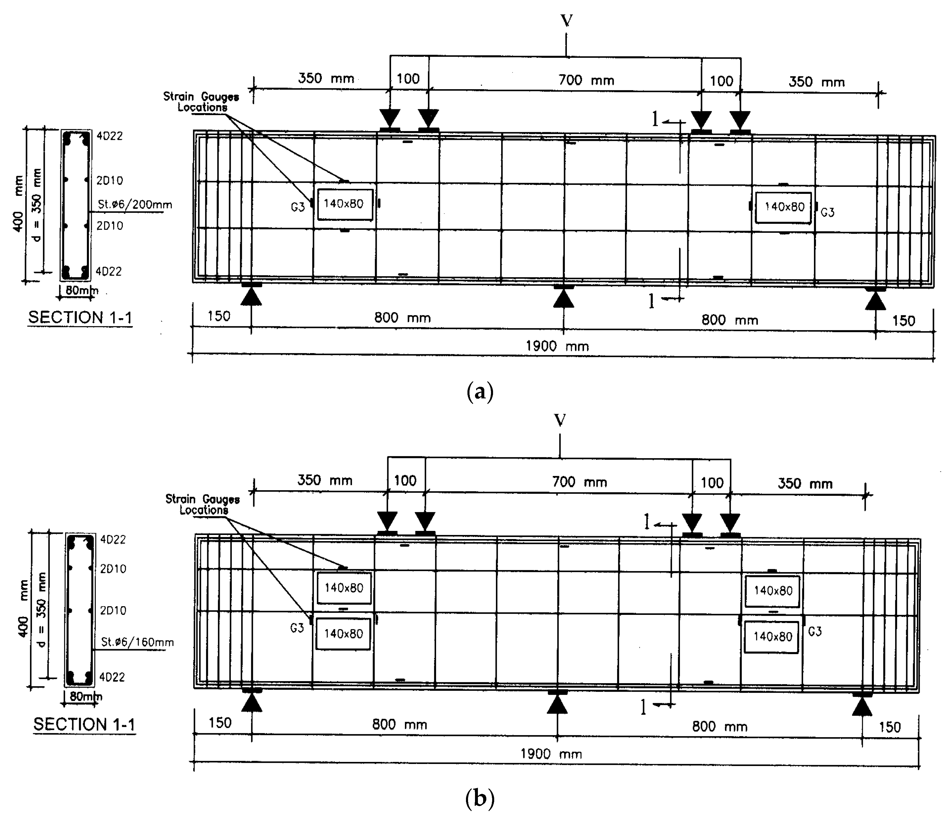
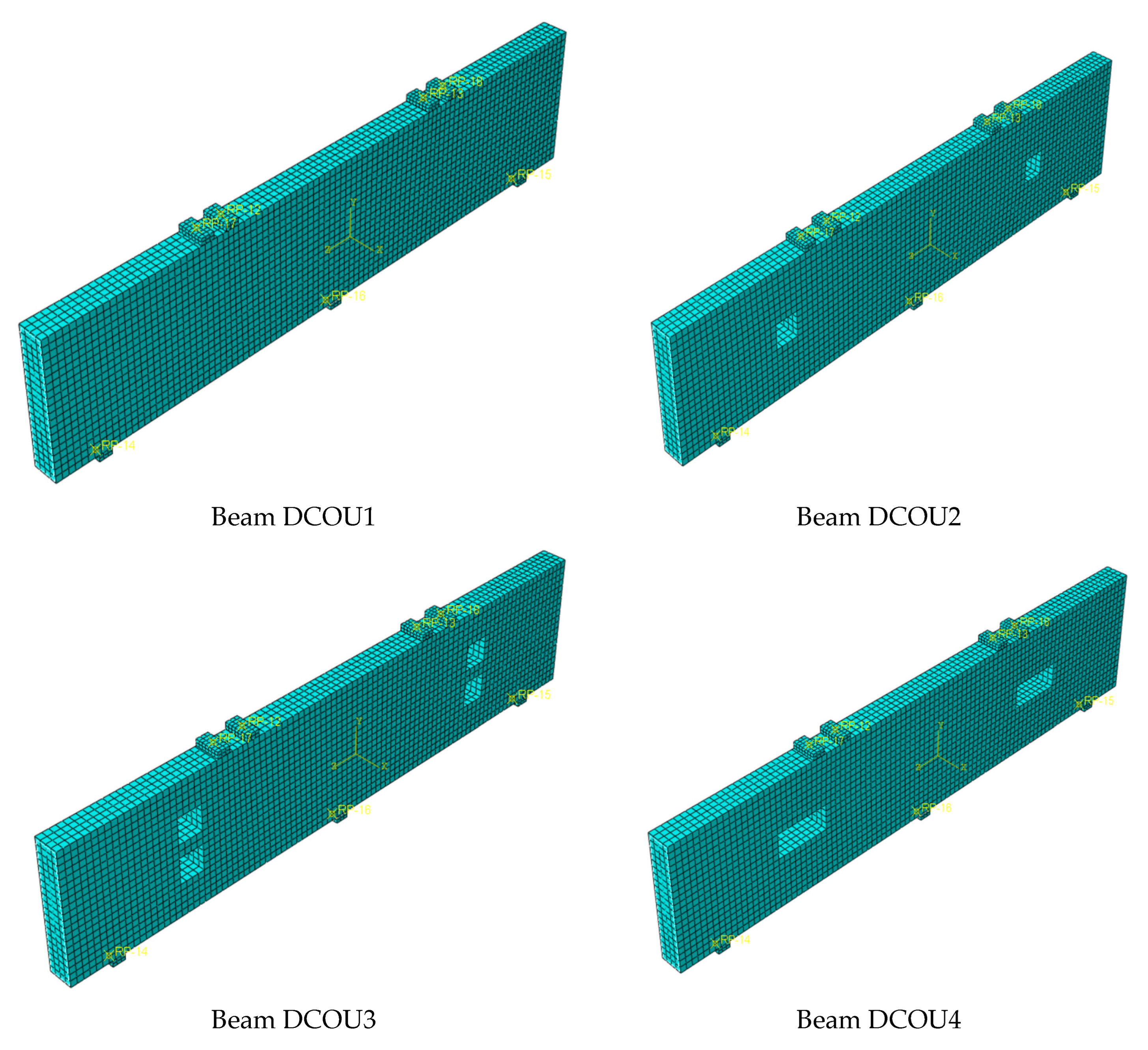
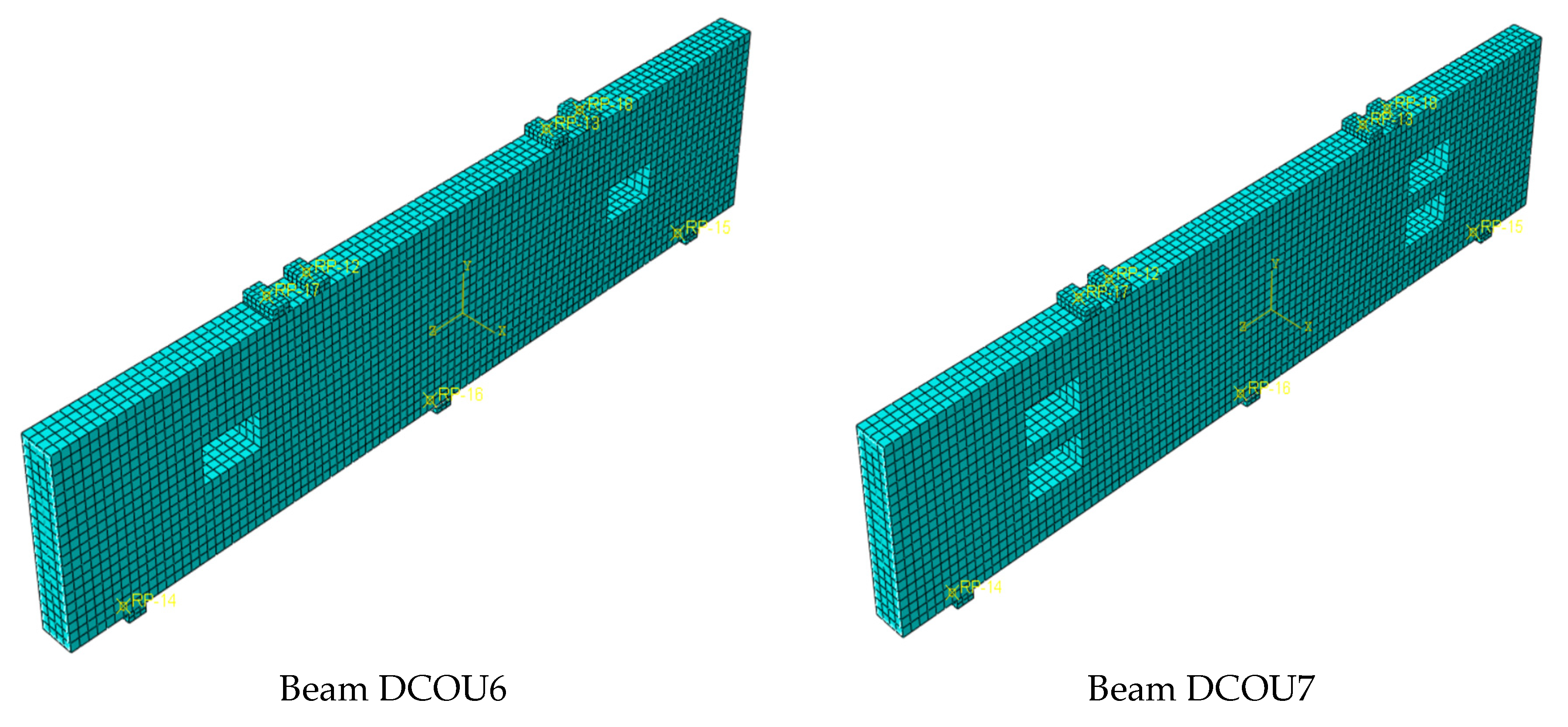
Seven UHPFRC two-span beam specimens with openings and one reference solid beam were included in the test program. All the beams had a width of 80 mm and a total height of 400 mm. The specimens were tested with the same span to depth ratio (le/d = 2.29) and the same ratio (a/d = 1.0). The bottom and top reinforcement of the specimens comprised four bars of diameter 22 mm (ρt = 5.43%) and had a fy of 426.3 MPa. The specimen notation contained four parts: the first part D refers to deep beam, C refers to continuous beam, O refers to opening, and U refers to UHPFRC. Detailed information on the tested specimens is given in Table 1. The continuous beams were reinforced with skin reinforcement (2D10 mm bars on each side), which covers the minimum required by ACI 318 [20], EC-2 [19], and ECP 203 [18]. Figure 1a shows the details of the reinforcement of specimens, with one opening in each exterior span. A little modification to the positions of the horizontal web bars was made to facilitate placing the second web opening without cutting these bars (Figure 1b).
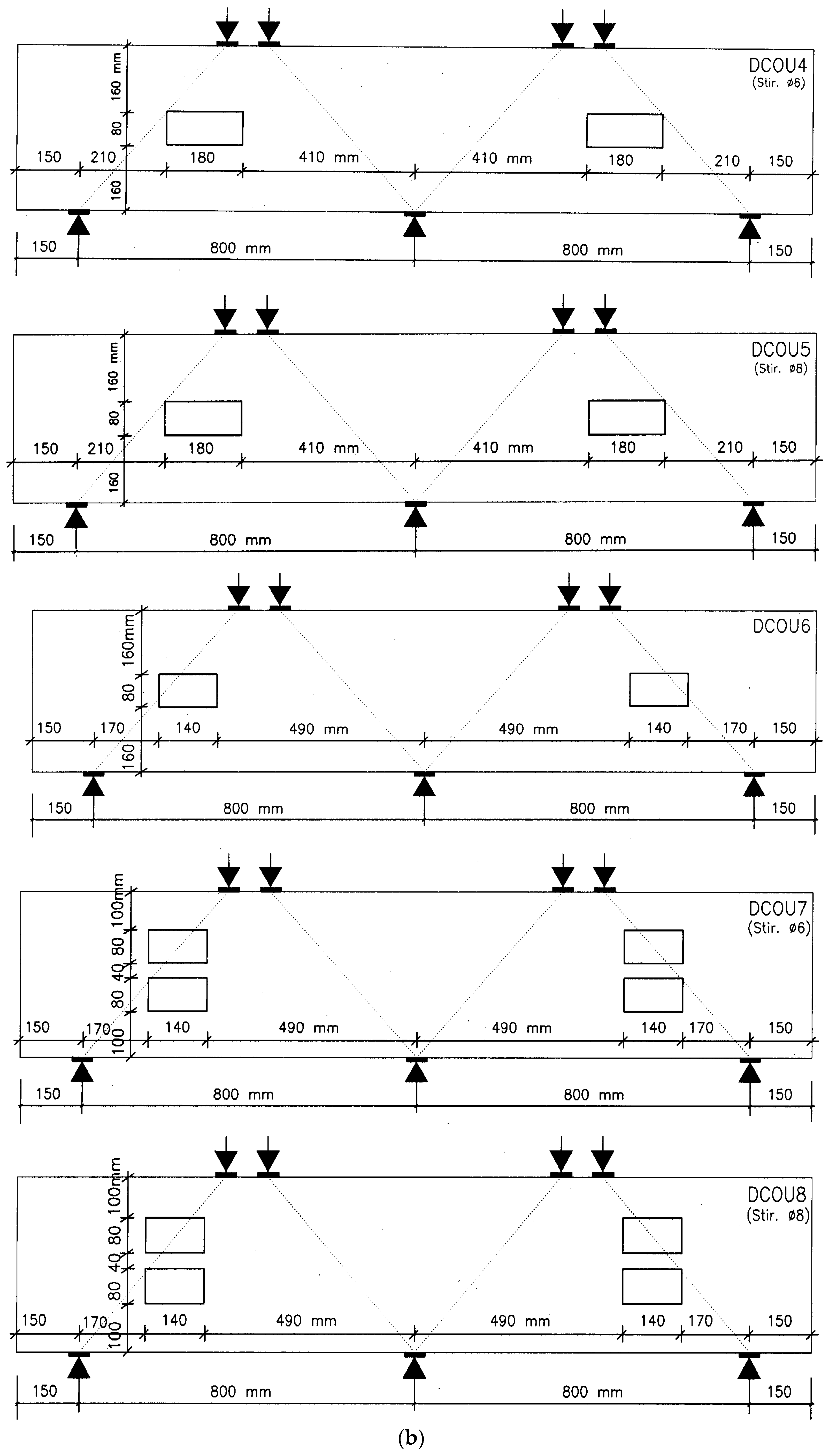
The ratio of stirrups ρv%, the position, width, and height of openings were the studied parameters, as given in Table 1. Stirrups with diameters of 6 mm or 8 mm were used, with fy = 397.2 and 312.7 MPa, respectively. The details of the stirrups are given in Table 2, with the minimum required by the codes. The area of stirrups Av covers Av,min, as adopted by the codes. The stirrups spacing sv was less than or equal to the maximum spacing sv,max of ECP-203-2020. The provided sv of DCOU1, DCOU2, DCOU3, DCOU6, DCOU7, and DCOU8 satisfied the minimum required by EC-2, except beams DCOU4 and DCOU5. The provided sv of all the tested continuous beams with openings was greatly higher than the sv,max adopted by ACI 318-2019. It should be noted that, according to this code, the vertical web reinforcement should be provided such that sv does not exceed the lesser of d/5 or 300 mm, where d is the effective depth of the beam. Table 2 shows that the provided sv for beams DCOU2 and DCOU3 was 43% more than the sv,max of ACI 318, while the provided sv for beams DCOU4 and DCOU5 was 186% more than the sv,max of ACI 318. The provided sv for beams DCOU6, DCOU7, and DCOU8 were 129% more than the sv,max of ACI 318. The size and position of openings in UHPFRC two-span continuous beams are shown in Figure 2. The openings were placed in the exterior shear span, so as to interrupt the load flow between the external support and the point of applied force. The width and place of the openings were changed according to the spacing between the stirrups. The height of one opening is 80 mm (20% of beam height). This means that making two identical openings in the same section causes a 40% reduction in total height.
3. UHPFRC Mix Materials
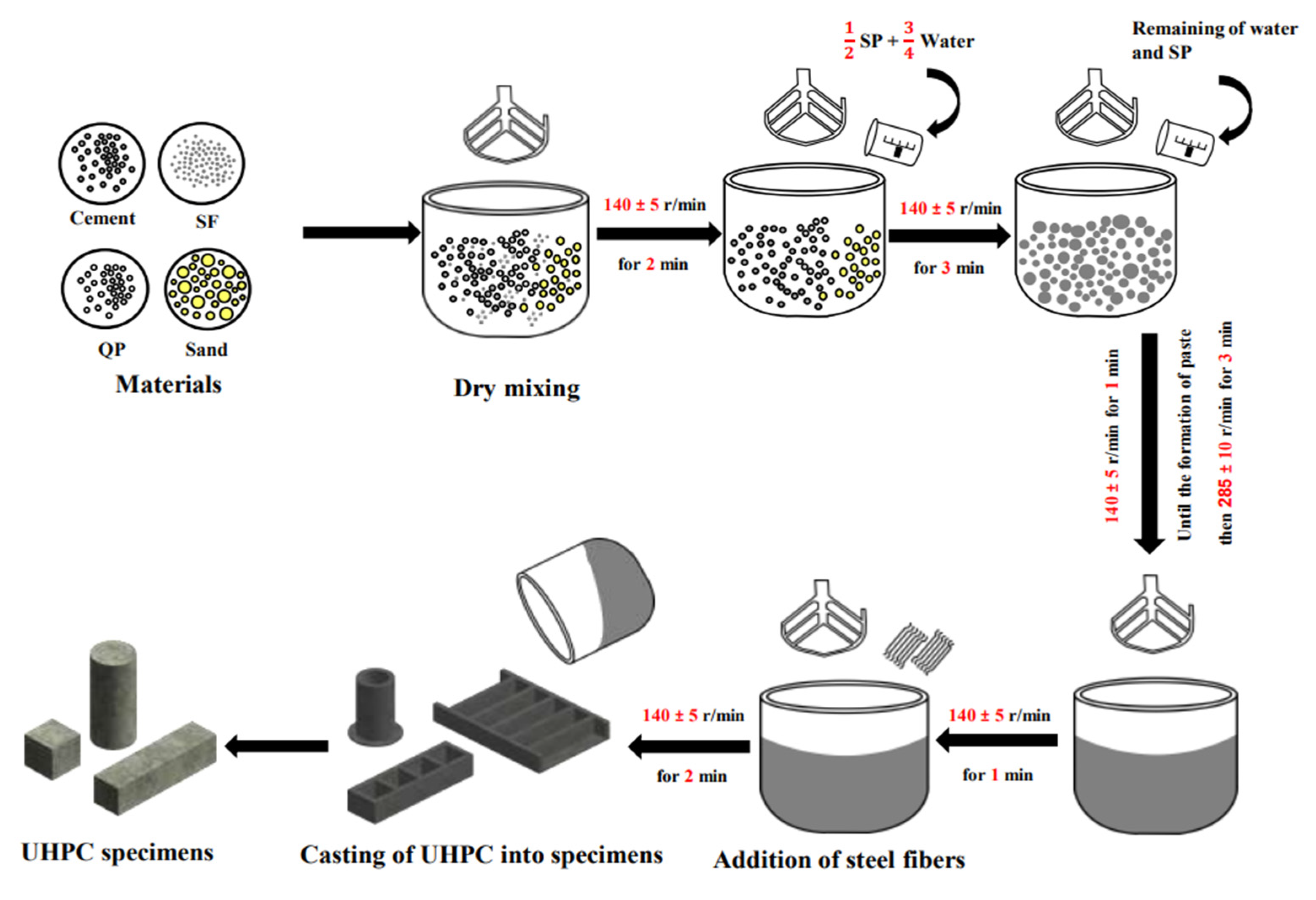
The UHPFRC mix proportions by weight per 1.0 m3 are given in Table 3. Portland cement grade 52.5 N, according to EN197-1 [49], with a fineness of 345 m2/kg, was utilized. Natural sand was used as fine aggregate, which possessed a specific gravity and maximum particle size of 2.65 and 4 mm, respectively. Crushed quartz powder with a mean diameter of about 20 µm and silica fume with a diameter of 1.0 µm to 0.1 µm and a specific surface area of 19,000 m2/kg were used. A new generation of high range water reducers was used [50]. The volume fraction of steel fibers of 1.5% was used in the UHPFRC mix. End-hooked steel fiber with a diameter of 0.2 mm and a length of 13 mm was used. The measured yield strength of steel fibers is equal to 552 MPa and the maximum tensile strength is 828 MPa. UHPC continuous beams were fabricated using a similar method as described in a previous study [10]. Mixing procedures are shown in Figure 3. Concrete specimens were cured within the first 24 h at room temperature (21 ± 2 °C), and then moist cured after demolding until the test ages. The cube concrete compressive strength fcu, based on 50 × 50 × 50 mm cubes, and the cylinder concrete compressive strength fc’, based on the 50 × 100 mm cylinder of the UHPFRC mix, were 143.5 MPa and 132.5 Mpa, respectively. The splitting cylinder tensile strength fsp, based on a 50 × 100 mm cylinder, and the flexural strength fr, based on 40 × 40 × 160 mm prisms, were 10.5 MPa and 30.5 MPa, respectively. Table 4 summarizes the mechanical properties of the UHPC mixtures. Tests were carried out according to ASTM standards [51,52,53,54].
4. Test Setup
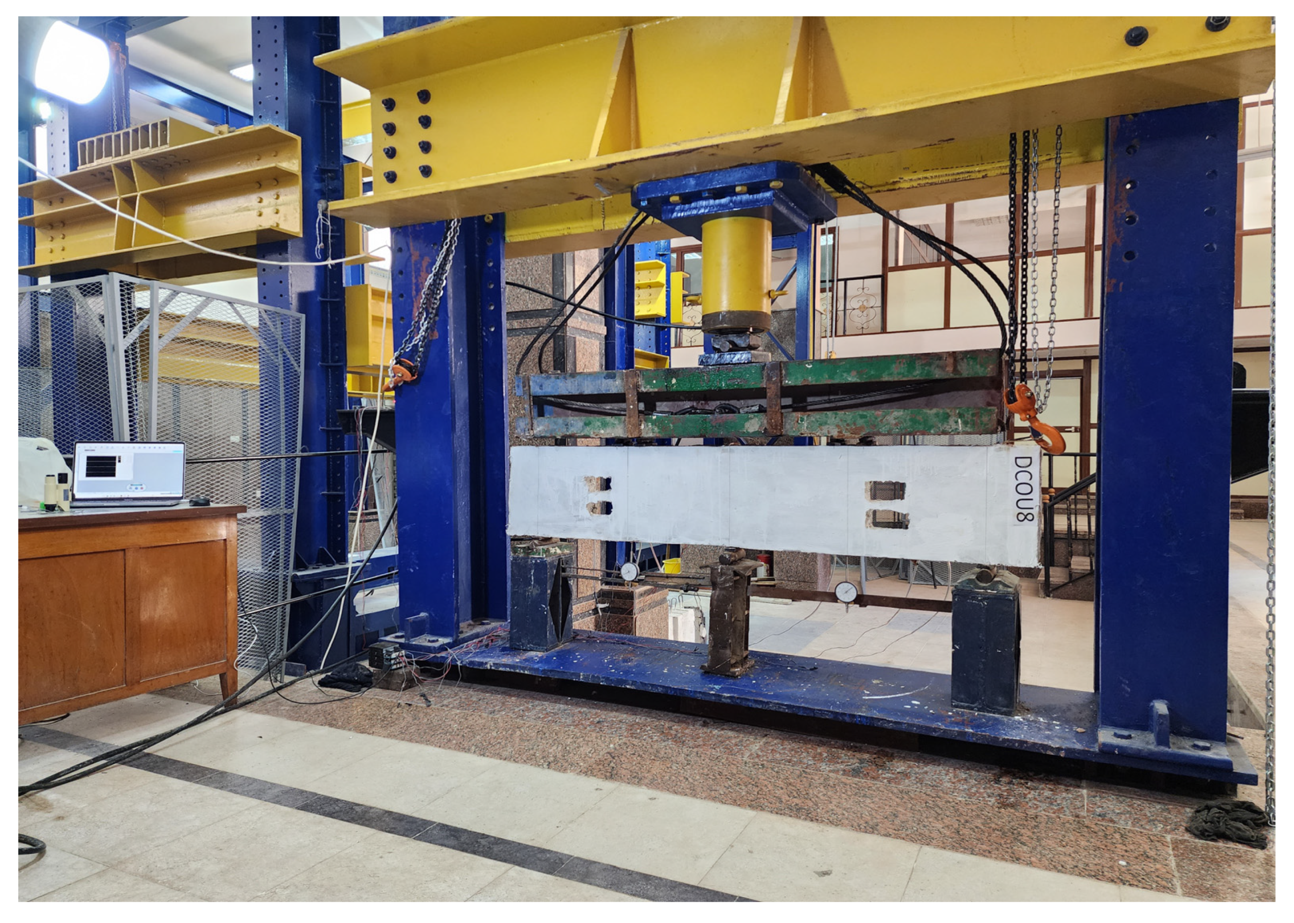
The two-span continuous specimens were tested in the loading frame of the concrete laboratory at the Faculty of Engineering, El-Mansoura University, with a total capacity of 2000 kN. The load was applied to the beams through a force-controlled jack, with a loading rate of 20 kN/min. In order to get four-point loads and three support reactions, special arrangements were made, as shown in the photograph in Figure 4. Steel plates of the same size (40 × 80 mm) and thickness (20 mm) were provided at the load points and at the supports. Each specimen was sufficiently instrumented to measure the mid-span deflection and the strains in the longitudinal bars and the stirrups. Electrical strain gauges were bonded to the stirrups, longitudinal bars, and skin bars at some critical points, as shown in Figure 1. Electric resistance 120 ohms Epoxy-based strain gauges with lengths of 15 mm and 20 mm were used. The mid-span displacements were measured using dial gauges with an accuracy of 0.01 mm. The widths of cracks were determined using a crack detection microscope (accuracy = 0.02 mm), and the propagations of cracks were marked on the surface of each deep beam.
5. Results
5.1. Failure Modes
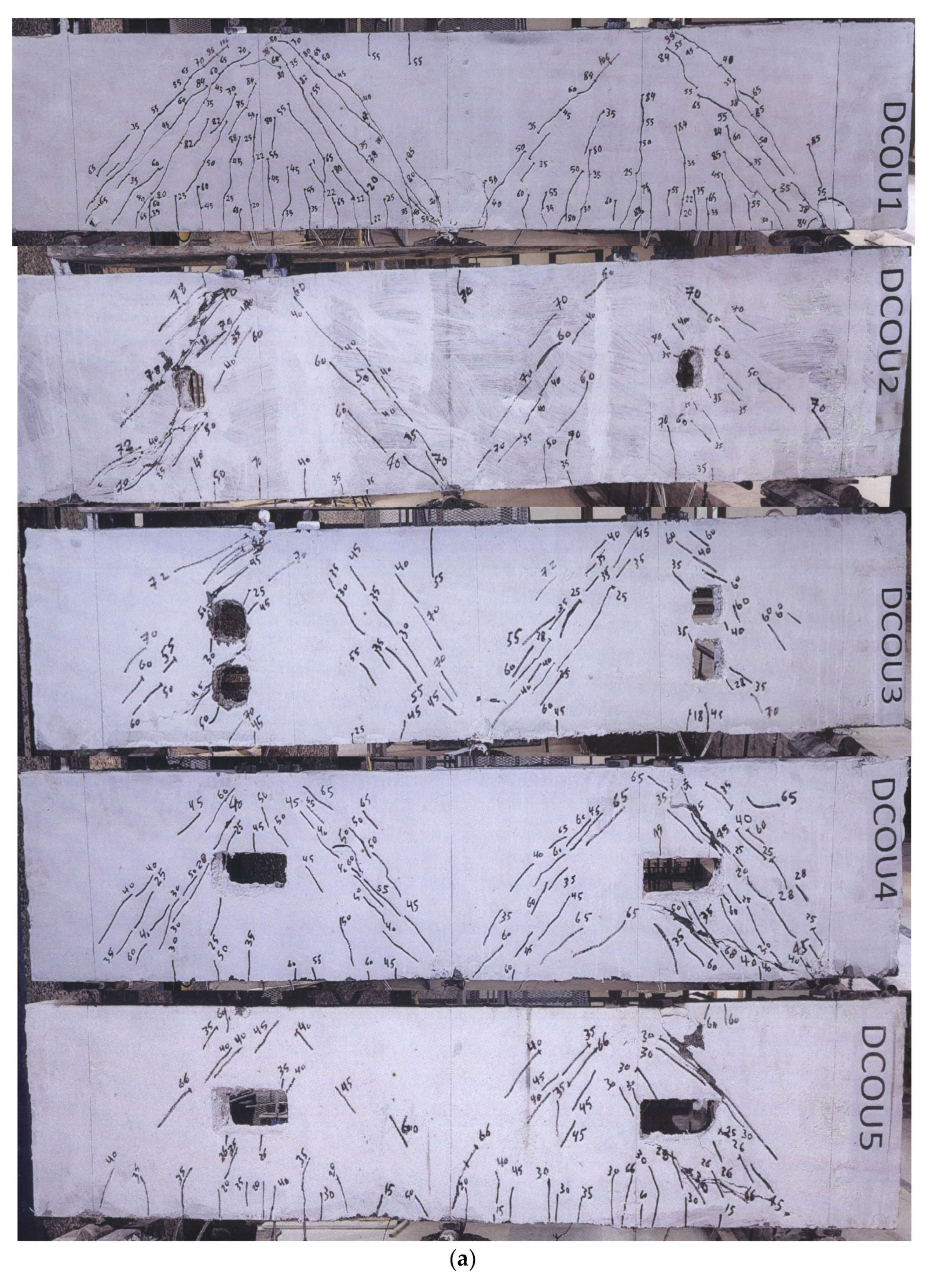
For the tested UHPFRC continuous beams, the first mid-span flexural crack approximately took place at the same time in the two spans. For a solid deep beam, the first shear crack is initiated at the mid-depth of the intermediate shear span. As the load increased, shear cracks developed in the zones between the load points and the supports. The width and length of these cracks increased with increasing the applied load. Just before failure, the cracks became wider. The first diagonal crack of DCOU1 was observed at a load of 31.0% of the failure load. The cracking patterns of inclined cracks were symmetrical for the two spans of the beam and gave the appearance of a tied-arch system, as shown in the photograph of DCOU1 in Figure 5a. At failure, the web reinforcement was yielding, and shear compression took place by concrete crushing at the diagonal strut through the major shear crack between the load and the support.
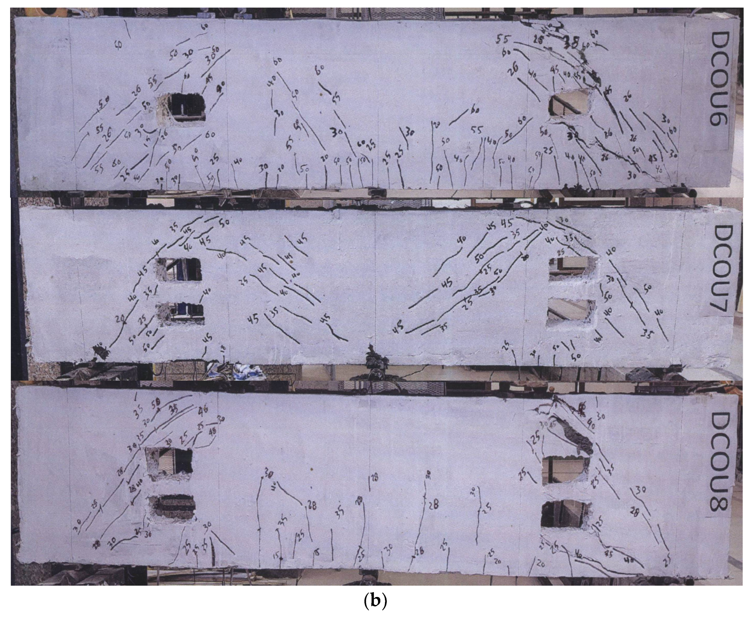
For the tested beams with openings, the diagonal crack developed at the top or bottom corner of the openings and was shorter than that of the solid beam (see the photographs in Figure 5). The loads of the first shear crack and the first flexural crack are given in Table 5. The average load of the initial shear crack of specimens with openings is 38.3% of the failure load. With the load increase, new cracks developed at the edges and corners of the openings. At an exterior shear span and around the openings, the width of cracks that occurred between the load (or the support) and the corners of the opening increased faster than the cracks that developed between the load plates and the intermediate support. A brittle failure mechanism took place very quickly, due to the diagonal shear fracture of the concrete diagonal compression strut passing through the opening at one of the exterior shear spans. At failure, two major shear cracks occurred: the first took place between the applied load and the upper inner corner of the opening, and the second was between the lower corner of the opening and the support. At failure, two blocks formed: one attached to the external support and the other attached to the central support (Figure 5). The stirrups arrangements did not have a noticeable influence on the mode of failure, since it occurred in the diagonal compression struts passing through the opening edges.
5.2. Ultimate Loads
The existence of openings in the exterior shear span of UHPFRC two-span continuous beams considerably reduced the ultimate capacity of the tested beams compared to similar solid beams, as shown in Table 5. The experimental total cracking loads (Vcrs and Vcrf) and total ultimate loads (Vu,EXP), as well as the ratio (Vcrs/Vu,EXP) of continuous specimens with and without web openings, are shown in Table 5. The average ratio (Vcrs/Vu,EXP) for continuous specimens with web openings was about 24.0% higher than the solid beam. The ultimate load Vu,EXP of DCOU2 (opening width = 80 mm) was equal to 68.4% of that of beam DCOU1 without opening. The recorded Vu,EXP of DCOU4 (opening width = 180) and DCOU6 (opening width = 140 mm) were equal to 59.7% and 57.0% of those of DCOU1, respectively. This showed that web openings of 20% height placed in the exterior shear span reduced the failure load of UHPFRC two-spans continuous deep beams by 31.6% to 43.0% compared with the reference beam. This showed that the reduction in the recorded ultimate load of the tested beams depends mainly on the width and location of the opening. Figure 2 shows the locations of openings on UHPFRC two-span continuous beams. The pass between the support and the applied load cuts a wider part of the openings of beam DCOU6 than that of beam DCOU4. The reduction of Vu,EXP increased with an increase in the height of the opening to 40%. The recorded Vu,EXP for beams DCOU3 and DCOU7 were equal to 63.2% and 45.6% of the solid beam, respectively. An opening of the height of 40% reduced Vu,EXP by 36.8% to 54.4% compared with the solid beam. It can be noted that Vu,EXP of beam DCOU3 (opening height = 40%) was only 92.3% of that of beam DCOU2 (opening height = 20%), while Vu,EXP of beam DCOU7 was 80.0% of that of beam DCOU6. Also, increasing the opening width reduced the Vu,EXP of the UHPFRC deep beams (Table 5). Comparing specimens with an opening height of 20% showed that Vu,EXP of DCOU4 was smaller than DCOU2 by 12.8%, while the Vu,EXP of DCOU6 was 16.7% smaller than DCOU2. Comparing beams with an opening height of 40% showed that the recorded Vu,EXP of beam DCOU7 was smaller than DCOU3 by 27.8%. This indicated that, for the tested specimens with openings of the same height, increasing the width of the opening from the two sides of the load pass increased the reduction of Vu,EXP.
Table 5 shows the effect of the provided transverse reinforcement ratio ρv% on Vu,EXP. For beam DCOU5 with a ρv equal to 0.63% (dv = 8 mm and sv = 200 mm, which is 186% more than sv,max of ACI 318-2019), the recorded ultimate load was slightly more than that of DSOU4 with ρv = 0.35% (dv = 6 mm) by about 1.5%, while the Vu,EXP of beam DCOU8 with a ρv equal to 0.79% (dv = 8 mm and sv = 160 mm, which is 129% more than sv,max of ACI 318-2019) was less than that of beam DCOU7 (with ρv = 0.44%) by about 1.9%. This indicated that, for continuous beams with similar openings, providing stirrups with a spacing of 129% more than sv,max adopted by ACI 318-2019 had a small effect on Vu,EXP. Increasing ρv% by 80% slightly increased (or decreased) the Vu,EXP of continuous deep beams, since the failure of these beams with openings was independent of the transverse reinforcement, and usually took place in the diagonal compression strut between the support and the applied force passing through the opening edges. For beams with openings with different heights and/or widths, increasing ρv% did not enhance the failure load, since the height and width of the opening are the main parameters controlling the shear performance of continuous specimens. This is indicated by the comparison between the recorded shear failure loads of beam DCOU8 (ρv = 0.79%) and DCOU6 (ρv = 0.44%).
5.3. Cracking Loads
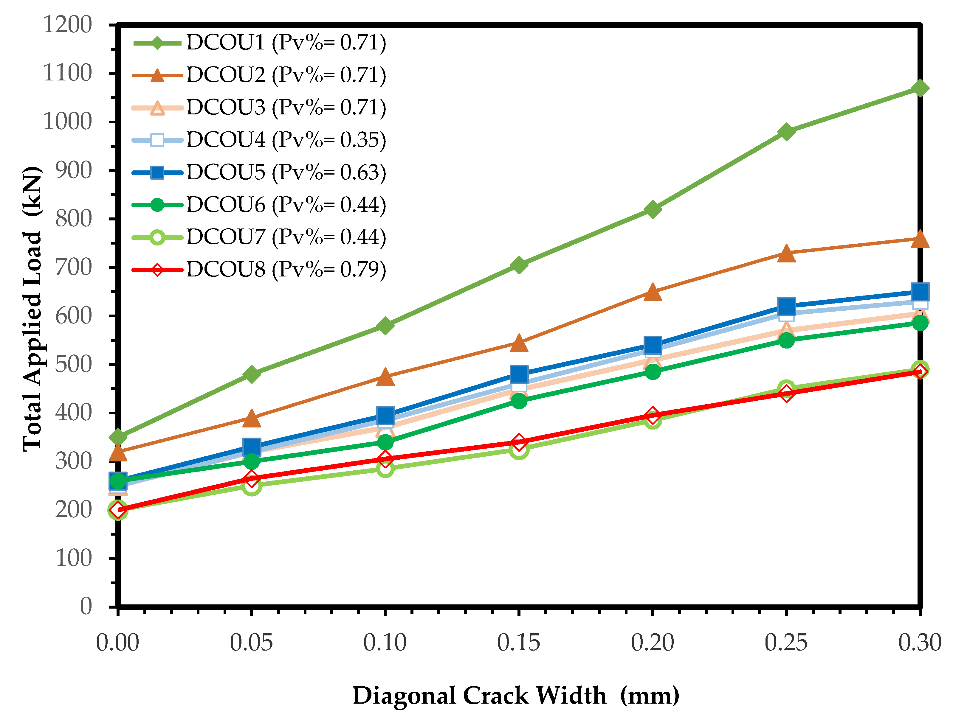
The total applied load versus the width of the recorded shear crack width for the continuous beam specimens is given in Figure 6. For beams with openings, the diagonal shear cracks were initiated earlier in the reference beam, as shown in Table 5. These cracks developed gradually with increasing loads. The recorded first cracking load Vcrs of beams DCOU2, DSOU4, and DCOU6 (having one opening) were 97.4%, 71.4%, and 74.3% of that of the solid beam, respectively. By increasing the opening height, Vcrs were considerably reduced. For beams DCOU3 and DCOU7, the recorded Vcrs were 71.4% and 57.1% of the solid beam, respectively. Increasing the opening width for the same opening height also reduced the recorded first diagonal load. For beam DCOU4 (with an opening width of 180 mm), the recorded Vcrs was 78.1% of that of beam DCOU2 (opening width = 80 mm), and the Vcrs of DCOU6 (opening width = 160 mm) was 81.3% of that of beam DCOU2. Increasing the transverse reinforcement ratio slightly enhanced the first cracking load and slightly reduced the width of these cracks in the tested specimens with the same opening size. Figure 5 shows that the development of the diagonal crack in beam DCOU4 (sv = 200 mm and ρv = 0.35%) was slightly faster than that of beam DCOU5 (with sv = 200 mm and ρv = 0.63%). The development of the diagonal crack in beam DCOU7 (sv = 160 mm and ρv = 0.44%) was also slightly faster than that of beam DCOU8 (with sv = 160 mm and ρv = 0.79%).
5.4. Load-Displacement Relationships
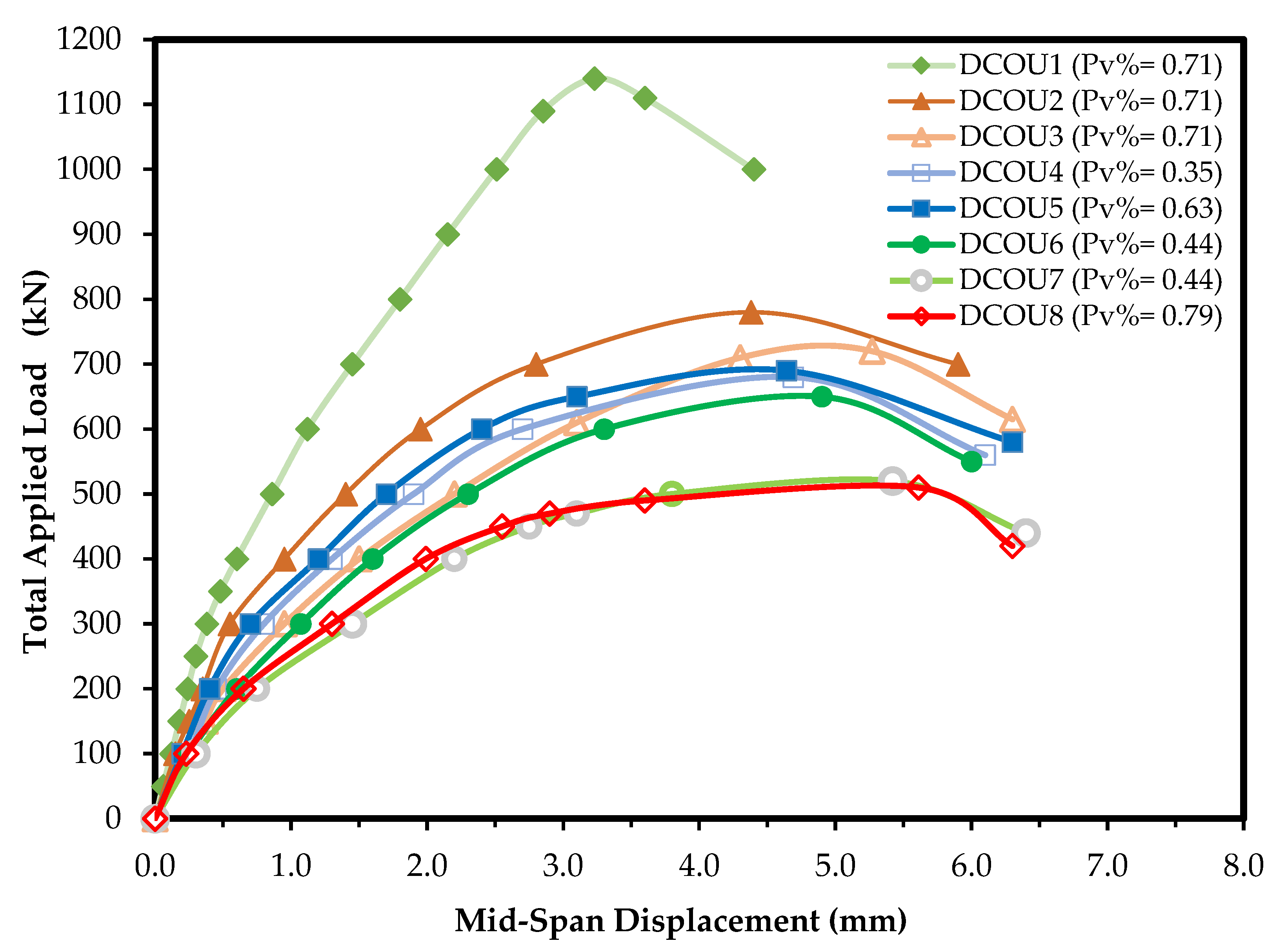
A plot of the total load applied by the jack versus the mid-span displacement for UHPFRC two-span continuous beams is shown in Figure 7. All displacement curves are for the failed span. The behavior of the beams was elastic in the first stages of loading. After increasing the applied load, beams with web openings produced displacements greater than those of the solid beam. Beam DCOU2, having the smallest web opening, showed the nearest load-displacement curve to the solid beam. For openings with the same width, height, and position, increasing the transverse reinforcement slightly enhanced the stiffness of the beams. Beam DCOU5 with ρv = 0.63% was slightly stiffer than beam DCOU4 with the same web opening, but with lower ρv = 0.35. Beam DCOU8 with ρv = 0.79% had approximately the same stiffness as beam DCOU7 with the same web opening and ρv = 57% of that of beam DCOU7. For the same opening width and same stirrups, increasing the opening height considerably reduced the overall stiffness of the specimens. The tested deep beam DSOU3 (opening height = 40% beam height) had a much lower stiffness than that of beam DSOU2 (opening height = 20% beam height). The same results were obtained from the comparison between beams DCOU6 and DCOU7. This indicated that increasing the width of the opening symmetrically around the load line considerably reduced the stiffness of the tested two-span UHPFRC continuous beams. For specimens with the same transverse reinforcement and opening height, beam DCOU8, with an opening width of 140 mm, had a stiffness much smaller than beam DCOU3 (width of opening 80 mm).
5.5. Strains Relationships
The strains of longitudinal bars in the mid span and over the central support were in tension with small values and approximately constant at each increment of load increase. After the initiation of flexural cracks at the middle of each span, the strains increased at the lower bars. The photographs in Figure 5 show that the tested continuous beams had failed in shear compression before the longitudinal bars reached the yield point. The development of shear cracks did not influence the recorded strains in these bars. Changing the opening size and position had a slight effect on the measured longitudinal steel strains.
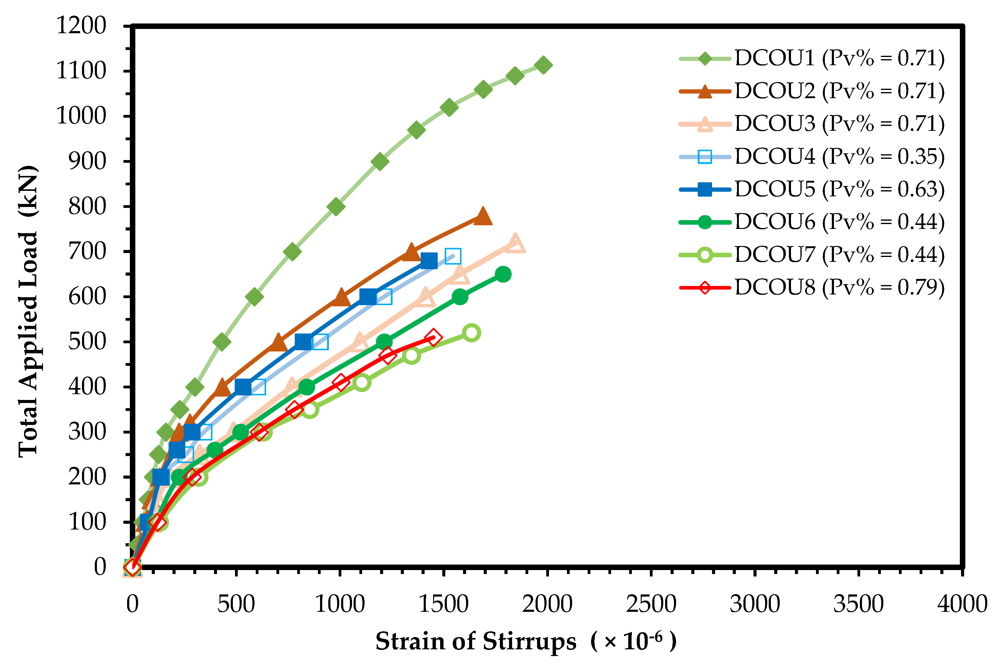
The recorded strain readings in the legs of the stirrup just beside the opening at the exterior support (gauge G3 in Figure 1) are given in Figure 8, versus the applied total load (Vu,EXP). Before the first diagonal crack, the strains in the stirrups were very slight, and a considerable increase happened after the initiation of this crack. Comparing the strains recorded in the stirrups showed that increasing the ratio of stirrups (by increasing dv and/or reducing sv) for the same web openings reduced the strains at the same shear force. The recorded strains in beam DCOU5 (with ρv = 0.63%) were smaller than those in beam DCOU4 (with ρv = 0.35%). The strains in the stirrups of beam DCOU1 without web openings reached the yield strain just before shear compression failure (yielding strain of stirrups with 6 mm diameter = 1980 × 10−6). The stirrups of the tested specimens with openings did not yield, as shown in Figure 7, since the failure took place early in the diagonal compression strut passing through the web opening in one of the exterior shear spans (yielding strain of stirrups with 8 mm diameter = 1560 × 10−6). The existence of web openings increased the recorded stirrup strains in comparison to the reference solid beam. The increase in height of the opening increased considerably the strains in the legs of the stirrups (the strain readings of DCOU3 and DCOU2 and the strain readings of DCOU7 and DCOU6). A comparison between beams DSOU4 and DSOU2 showed that increasing the opening width increased the recorded stirrups strains at the same applied load.
6. Numerical Modeling for UHPFRC Two-Span Continuous Deep Beams
6.1. Proposed Model
A 3-D numerical model using the computer program ABAQUS [55] is proposed and used to predict the performance of two-span beam specimens with openings. This code included nonlinear constitutive models for concrete and reinforcing bars. A 3-D solid element C3D8R with eight nodes modeled the concrete. This concrete element can be cracked in tension and crushed in compression. It is defined by eight nodes with three degrees of freedom at each node. This program used the concrete damage plasticity model (CDP) to simulate the concrete’s behavior with degradation under both compression and tension. The CDP model assumes that the two main failure mechanisms of concrete are compressive crushing and tensile cracking. Two damage parameters are used to identify the degradation of elastic stiffness. These parameters can take values from zero to one (zero for undamaged material and one for fully damaged material). Five plasticity parameters of CDP are defined in the Drucker–Prager plastic flow function and the yield function. These parameters are the dilation angle ψ, the eccentricity, the ratio of biaxial compressive strength to uniaxial compressive strength (σbo/σco), the viscosity parameter, and the ratio of the second stress invariant on the tensile meridian to that of the compressive meridian Kc. A dilation angle of 30° was used in the model of the studied specimens. The eccentricity of 0.10, which is a default of the ABAQUS code, and a value of the ratio (σbo/σco) of 1.16 were used. The viscosity parameter was assumed to be 0.0001 and a value of (2/3) for the Kc parameter was adopted. The stress–strain relationships for UHPFRC in compression and tension adopted by Al-Kabasi et al. [56] were used in the proposed model. In this study, the maximum direct tensile strength of UHPFRC was taken to be equal to 8.0 MPa, as recommended in the previous design guidelines for UHPC [15,16,17]. The Poisson’s ratio of UHPFRC was taken to be equal to 0.2. For UHPFRC in this study, the elasticity modulus was estimated using a simple expression (Ec = 3737 fcu0.5 MPa) [38]. The experimental cube compressive strength fcu is equal to 143.5 MPa and the calculated value of Ec is equal to 44,770 MPa.
The beam reinforcement of the studied specimens was treated as embedded 3-D truss element (T3D2) smeared inside the solid element. This bar element is a linear two-node displacement element that uses linear displacement interpolation and has constant stress. The contact between the steel plates and the concrete (at the loading points and at the supports) was simulated as tie contact. Rigid body interactions were applied. The boundary conditions for the tested beam specimens were simulated in the numerical model. Two exterior roller supports (with u2 = 0.0 but u1 and u3 ≠ 0.0) and one intermediate hinged support (with u1 = u2 = u3 = 0.0) were considered for the continuous beams. Detailed information about elements and models can be found in the manual of the ABAQUS code [55]. It should be noted that the accuracy of the numerical results of the ABAQUS code when applied to UHPFRC simply supported beams were ensured in many previous numerical investigations [56,57,58,59].
Each continuous specimen can be meshed according to details of reinforcement, position, and size of openings. The finite element meshing of two-span continuous beams is shown in Figure 9. A mesh element of concrete with a size of 20 × 20 × 20 mm was used for the specimens. In this study, the reinforcing steel is modeled as an elastic-perfectly plastic material, the reinforcement modulus of elasticity Es is assumed to be 2 × 10⁵ MPa, and the Poisson’s ratio is taken as 0.30. The bond between rebars and concrete is assumed to be perfect.
6.2. Validation of Numerical Results
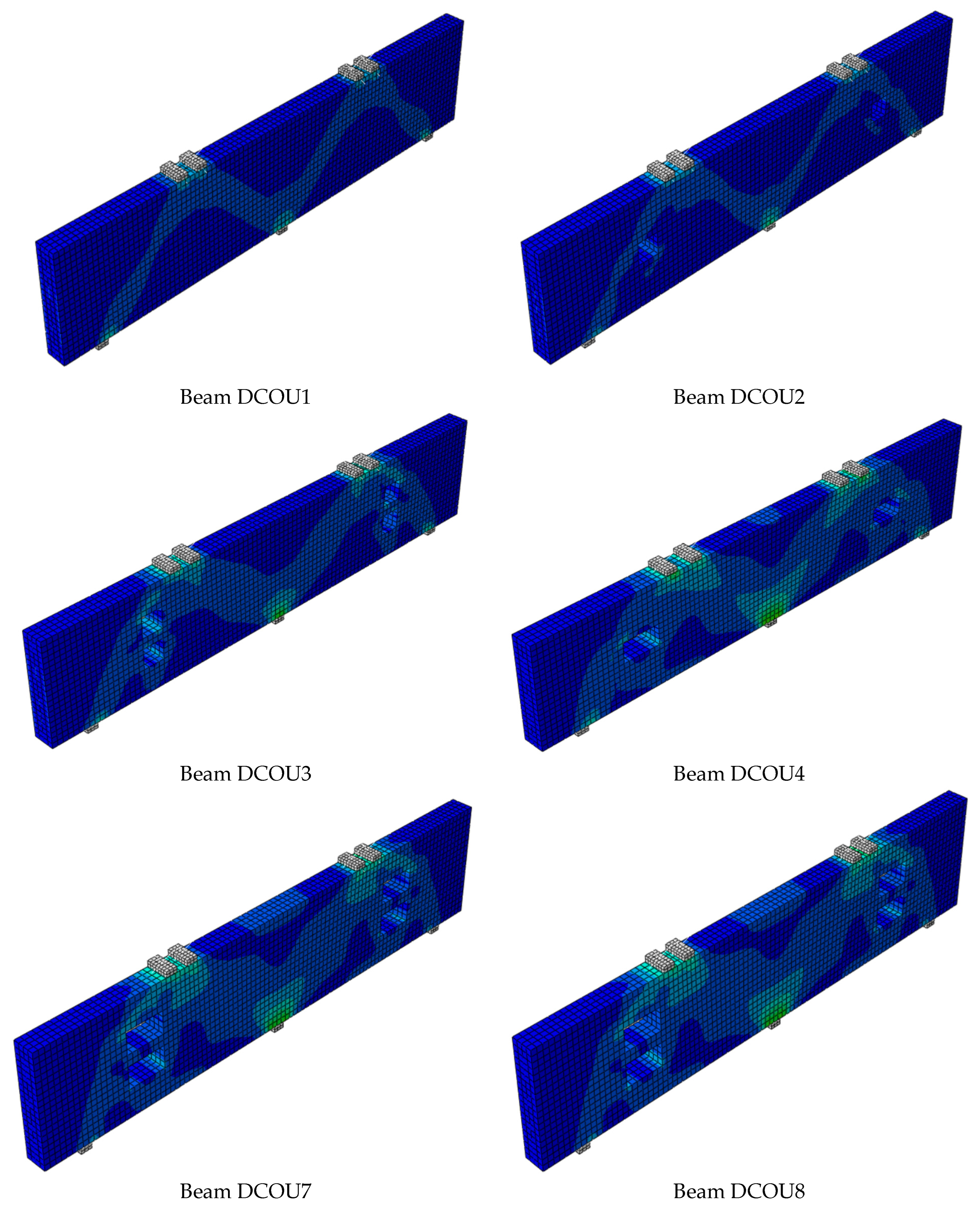
In Table 6, The mode of failure of the tested two-span continuous beams using the proposed numerical model is compared with the experimental failure modes. The comparison shows similar failure modes. Figure 10 shows the shapes of the stress distribution just before the shear failure of the continuous beams predicted from the numerical model. A comparison between Figure 10 and the photographs in Figure 5a,b shows that the predicted failure modes and the stress distribution of the tested specimens are greatly similar to the results of the experimental tests. The opening size and location controlled the effectiveness of the diagonal compression struts between the load and the exterior supports. Increasing the opening size (width and/or height) considerably reduced the width of the diagonal strut, and consequently reduced the failure load. This shows that the proposed numerical model can successfully predict the stress distribution and modes of failure for UHPFRC continuous beams.
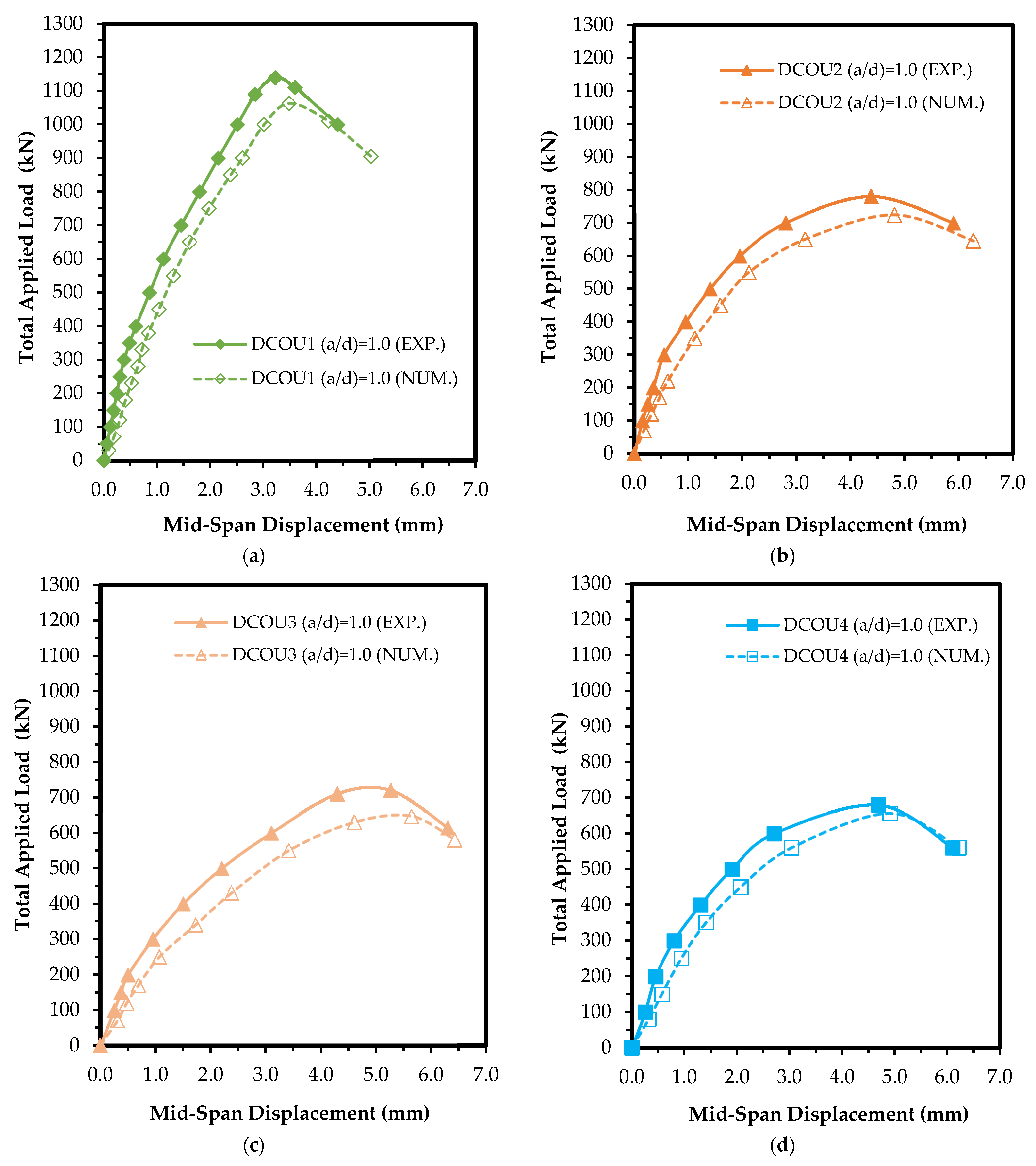
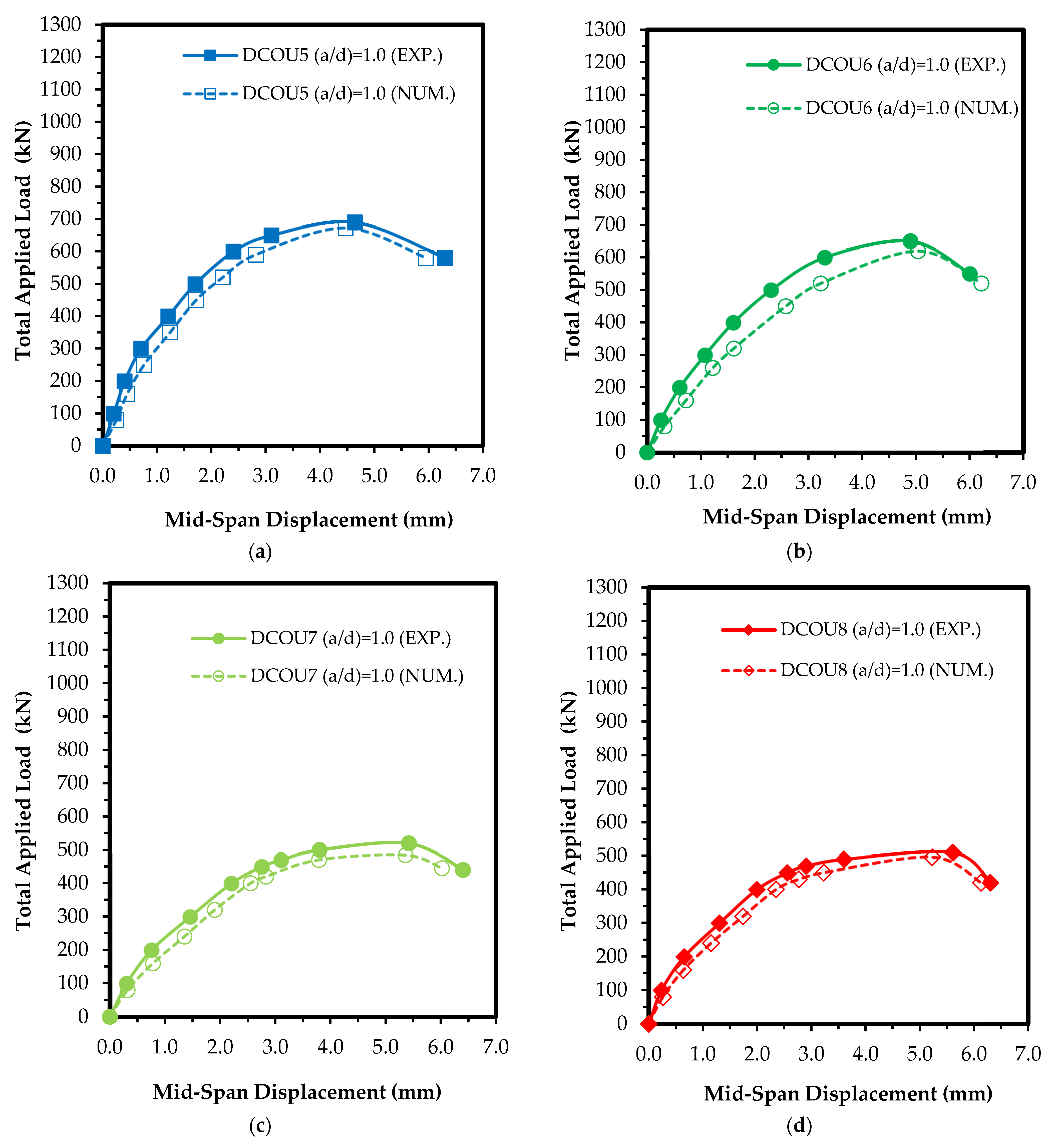
Table 6 shows a contrast between the failure load Vu,EXP and that estimated from the numerical model Vu,NUM. The average of (Vu,EXP/Vu,NUM) for two-span continuous beam specimens with openings is 1.058 (without DCOU1), and the coefficient of variation is equal to 2.77. This indicates that the numerical model gives reliable estimates of the failure load of two-span continuous beam specimens with openings. The predicted and the experimental mid-span displacements are given in Table 6. The average of (Δu,EXP/Δu,NUM) of the specimens with openings is equal to 0.985, with a coefficient of variation equal to 5.47. The experimental and predicted curves of mid-span displacements for the continuous beams are also compared in Figure 11 and Figure 12. These figures show that reasonable concurrence has been achieved between numerical and experimental results. The results showed that this model provides a good tool for predicting the capacity and deformations of two-span continuous UHPFRC beams with and without openings.
7. Conclusions
This experimental and numerical investigation was carried out to study the performance of UHPFRC two-span continuous beams. Eight continuous deep beam specimens were tested in shear. The stirrups spacing sv of all the tested specimens was (43% to 186%) more than the maximum spacing svmax of ACI 318-2019. The following can be concluded:
- The failure mode of UHPFRC two-span continuous beams with openings in the exterior shear span depends essentially on the position, height, and width of the opening. The failure takes place in the diagonal strut at the load line passing through the upper opening edge or/and the support and the lower opening edge.
- The maximum spacing between stirrups sv,max of ACI 318-2019 for normal reinforced concrete was not suitable for UHPFRC. For specimens with the same opening width, height, and position, providing stirrups with a spacing 129% greater than the maximum required by ACI 318 code had no considerable effect on the first shear cracking load or failure load.
- Web openings with a height of 20% of the beam height placed in the exterior shear span reduced the failure shear load of two-span continuous beam specimens by a ratio between 31.6% and 43.0% compared with the similar beam without opening.
- Openings with a height of 40% of the beam height reduced the failure load of continuous UHPFRC specimens by 36.8% to 54.4% when compared with a similar beam without an opening.
- Increasing the opening width by about 75% more than that of a similar UHPFRC continuous beam with the same opening height and position reduced the first crack load and failure load by 20.0% and 27.8%, respectively.
- Openings in the exterior shear span of continuous UHPFRC beam specimens considerably increased the deflections, strains in the stirrups, and diagonal cracks width.
- The proposed 3-D numerical model successfully predicted the shear strength and performance of UHPFRC two-span continuous beams with and without openings in the exterior shear span. It gives an ultimate load of about 94% of the experimental one.
Author Contributions
Conceptualization, A.M.Y. and A.M.T.; methodology, A.M.T. and M.S.A.-E.; software, A.M.Y. and M.S.A.-E.; validation, A.M.Y., A.M.T. and M.S.A.-E.; formal analysis, A.M.Y. and M.S.A.-E.; investigation, M.S.A.-E.; resources, M.S.A.-E.; data curation, A.M.Y. and A.M.T.; writing—original draft preparation, M.S.A.-E.; writing—review and editing, A.M.Y. and A.M.T.; supervision, A.M.Y. and A.M.T. All authors have read and agreed to the published version of the manuscript.
Funding
This research received no external funding.
Data Availability Statement
Data will be made available on request.
Conflicts of Interest
The authors declare no conflict of interest.
References
- Benjamin, A.G.; Marshall, D. Cylinder or Cube: Strength Testing of 80 to 200 MPa (11.6 to 29 Ksi) Ultra-High-Performance Fiber-Reinforced Concrete. ACI Mater. J. 2008, 105, 603–609. [Google Scholar]
- Strategic Development Council. Ultra High-Performance Concrete (UHPC): What It Is, Its History, and Why We Care; Strategic Development Council: Chicago, IL, USA, 2011; pp. 7–20. [Google Scholar]
- Wille, K.; Naaman, A.E.; Parra-Montesions, G.J. Ultra-High-Performance Concrete with Compressive Strength Exceeding 150 MPa (22 ksi), A simpler Way. ACI Mater. J. 2011, 108, 46–54. [Google Scholar]
- ACI Committee 363. Ultra High-Performance Concrete, A State-of-the-Art Report for the Bridge Community; Publication No. FHWA-HRT-13-060; United States Federal Highway Administration, Office of Infrastructure Research and Development: Washington, DC, USA, 2013; pp. 13–44.
- Yoo, D.Y.; Yoon, Y.S.A. Review on Structural Behavior, Design and Application of Ultra-High-Performance Fiber-reinforced Concrete. Int. J. Concr. Struct. Mater. 2016, 10, 125–142. [Google Scholar] [CrossRef] [Green Version]
- Tahwia, A.M. Performance of Ultra-High-Performance Fiber Reinforced Concrete at High Temperature. Int. J. Eng. Innov. Technol. IJEIT 2017, 6, 1–7. [Google Scholar]
- Tahwia, A.M.; Elgendy, G.M.; Amin, M. Durability and Microstructure of Eco-Efficient Ultra-High-Performance Concrete. Constr. Build. Mater. 2021, 303, 124491. [Google Scholar] [CrossRef]
- Tahwia, A.M.; Elgendy, G.M.; Amin, M. Mechanical Properties of Affordable and Sustainable Ultra-High-Performance Concrete. Case Stud. Constr. Mater. 2022, 16, e01069. [Google Scholar] [CrossRef]
- Tahwia, A.M.; Abd Ellatief, M.; Heneigel, A.M.; Abd Elrahman, M. Characteristics of eco-friendly ultra-high performance geopolymer concrete incorporating waste materials. Ceram. Int. 2022, 48, 19662–19674. [Google Scholar] [CrossRef]
- Tahwia, A.M.; Essam, A.; Tayeh, B.A.; Abd Elrahman, M. Enhancing Sustainability of Ultra-High Performance Concrete Utilizing High-Volume Waste Glass Powder. Case Stud. Constr. Mater. 2022, 17, e01648. [Google Scholar] [CrossRef]
- Akeed, M.H.; Qaidi, S.; Faraj, R.H.; Mohammed, A.S.; Emad, W.; Tayeh, B.A.; Azevedo, A.R. Ultra High-Performance Fiber-Reinforced Concrete. Part I: Developments, Principles, Raw Materials. Case Stud. Constr. Mater. 2022, 17, e01290. [Google Scholar] [CrossRef]
- Akeed, M.H.; Qaidi, S.; Faraj, R.H.; Mohammed, A.S.; Emad, W.; Tayeh, B.A.; Azevedo, A.R. Ultra-High-Performance Fiber-Reinforced Concrete. Part IV: Durability Properties, Cost Assessment, Applications, and Challenges. Case Stud. Constr. Mater. 2022, 17, e01271. [Google Scholar] [CrossRef]
- Tahwia, A.M.; Hamido, M.A.; Elemam, W.E. Using Mixture Design method for Developing and Optimizing Eco-Friendly Ultra-High Performance Concrete Characteristics. Case Stud. Constr. Mater. 2023, 18, e01807. [Google Scholar] [CrossRef]
- Abdellatief, M.; AL-Tam, S.M.; Elemam, W.E.; Alanazi, H.; Elgendy, G.M.; Tahwia, A.M. Development of Ultra-High-Performance Concrete with Low Environmental Impact Integrated with Metakaolin and Industrial Wastes. Case Stud. Constr. Mater. 2023, 18, e01724. [Google Scholar] [CrossRef]
- Association Francaise du Genil Civil (AFGC). Ultra High-Performance Fiber Reinforced Concrete; French Association of Civil Engineering: Paris, France, 2013. [Google Scholar]
- Korea Concrete Institute. Design Recommendations for Ultra High-Performance Concrete (K-UHPC), KCI-M-12-003; Korea Concrete Institute: Seoul, Republic of Korea, 2012. [Google Scholar]
- Japan Society of Civil Engineers (JSCE). Recommendations for design and construction of ultra high-strength fiber reinforced concrete structures. In Concrete Engineering Series; Japan Society of Civil Engineers: Tokyo, Japan, 2008. [Google Scholar]
- ECP 203-2020; Egyptian Code for Design and Construction of Reinforced Concrete Structures. Ministry of Housing, Utilities and Urban Communities: Cairo, Egypt, 2017.
- Eurocode 2; Design of Concrete Structures, Part 1–6: General Rules and Rules for Buildings. European Committee for Standardization: Brussels, Belgium, 2006; p. 253.
- ACI 318-19; ACI Committee 318, Building Code Requirements for Reinforced Concrete and Commentary. American Concrete Institute: Farmington Hills, MI, USA, 2019.
- Ashour, A.F. Tests of Reinforced Concrete Continuous Deep Beams. ACI Struct. J. 1997, 94, 3–12. [Google Scholar]
- Subedi, N.K. Reinforced Concrete Two-Span Continuous Deep Beams. Proc. Inst. Civ. Eng. Struct. Build. J. 1998, 128, 12–25. [Google Scholar] [CrossRef] [Green Version]
- Ashour, A.F.; Rishi, G. Tests of Reinforced Concrete Continuous Deep Beams with Web Openings. ACI Struct. J. 2000, 97, 418–426. [Google Scholar]
- Abdel Hafez, M.A. Nonlinear Analysis and Behavior of Reinforced Concrete Continuous Deep Beams under Concentrated Static Loads. Master’s Thesis, Structural Engineering, Faculty of Engineering, Cairo University, Cairo, Egypt, 2000. [Google Scholar]
- Yousef, A.M.; El-Metwaaly, S.E.; Hashem, M.F.; El-Mansy, A.M. Behavior of Reinforced HSC Continuous Deep Beams with Openings. Sci. Bull. Fac. Eng. Ain Shams Univ. 2005, 40, 1–20. [Google Scholar]
- Yang, K.H.; Ashour, A.F. Effectiveness of Web Reinforcement around Openings in Continuous Concrete Deep Beams. ACI Struct. J. 2008, 105, 414–424. [Google Scholar]
- Beshara, F.B.; Shaaban, I.G.; Mustafa, T.S. Behavior and analysis of reinforced concrete continuous deep beams. In Proceedings of the 12th Arab Structural Engineering Conference, Tripoli, Libya, 16–18 December 2013; Civil Engineering Department, Faculty of Engineering, University of Tripoli: Tripoli, Libya, 2012. Available online: https://www.researchgate.net/publication/29183277 (accessed on 12 June 2023).
- Rashwan, M.M.; Elsayed, A.A.; Abdallah, A.M.; Hassanean, M.A. Behavior of High Performance Continuous R. C. Deep Beams with Openings and Its Strengthening. J. Eng. Sci. Assiut Univ. Fac. Eng. 2014, 42, 1138–1162. [Google Scholar]
- Abdul-Razzaq, K.S.; Jalil, A.M. Behavior of reinforced concrete continuous deep beams-literature review. In Proceedings of the the Second Conference of Post Graduate Researches (CPGR’2017), Baghdad, Iraq, 4 October 2017; College of Engineering, Al-Nahrain Univ.: Baghdad, Iraq, 2017. [Google Scholar]
- Makki, O.M.; Al-Mutairee, H.M. Continuous deep beams behavior under static loads: A review study. In IOP Conference Series: Earth and Environmental Science; IOP Publishing: Atlanta, GA, USA, 2022. [Google Scholar]
- Voo, Y.; Poon, W.K.; Foster, S.J. Shear Strength of Steel Fiber-Reinforced Ultra High-Performance Concrete Beams without Stirrups. J. Struct. Eng. 2010, 136, 1393–1400. [Google Scholar] [CrossRef]
- Yang, I.H.; Joh, C.; Lee, J.W.; Kim, B.S. An Experimental Study on Shear Behavior of Steel Fiber-Reinforced Ultra High Performance concrete Beams. J. Korean Soc. Civ. Eng. 2012, 32, 55–64. [Google Scholar]
- Aziz, O.Q.; Ali, M.H. Shear Strength and Behavior of Ultra-High Performance Fiber Reinforced Concrete (UHPC) Deep Beams without Web Reinforcement. Int. J. Civ. Eng. IJCE 2013, 2, 85–96. [Google Scholar]
- Baby, F.; Marchand, P.; Toutlemonde, F. Shear Behavior of Ultra-High Performance Fiber-Reinforced Concrete Beams—I: Experimental investigation. J. Struct. Eng. ASCE 2014, 140, 04013111. [Google Scholar] [CrossRef]
- Baby, F.; Marchand, P.; Toutlemonde, F. Shear Behavior of Ultra-High Performance Fiber-Reinforced Concrete Beams—II: Analysis and design provisions. J. Struct. Eng. ASCE 2014, 140, 04013112. [Google Scholar] [CrossRef]
- Lim, W.-Y.; Hong, S.-G. Shear Test for Ultra-High Performance Fiber Reinforced concrete (UHPFRC) Beams with shear reinforcement. Int. J. Concr. Struct. Mater. 2016, 10, 177–188. [Google Scholar] [CrossRef] [Green Version]
- Yousef, A.M.; Tahwia, A.M.; Mareamy, N.A. Shear Behavior of Ultra–High Performance Fiber Reinforced Concrete Beams with Minimum Web Reinforcement. Int. J. Sci. Eng. Res. 2017, 9, 2000–2011. [Google Scholar]
- Yousef, A.M.; Tahwia, A.M.; Mareamy, N.A. Minimum Shear Reinforcement for Ultra-High-Performance Fiber Reinforced Concrete Deep Beams. J. Constr. Build. Mater. 2018, 184, 177–185. [Google Scholar] [CrossRef]
- Solhmirzaei, R.; Salehi, H.; Kodour, V.; Naser, M. Machine Learning Framework for Predicting Failure Mode and Shear Capacity of Ultra High Performance Concrete Beams. Eng. Struct. 2020, 224, 111221. [Google Scholar] [CrossRef]
- Bermudez, M.; Wen, K.; Hung, C. A Comparative Study on the Shear Behavior of UHPC Beams with Macro Hooked-End Steel Fibers and PVA Fibers. Materials 2022, 15, 1485. [Google Scholar] [CrossRef]
- Chen, B.; Zhou, J.; Zhang, D.; Su, J.; Nuti, C.; Senna, K. Experimental Study on Shear Performances of Ultra-High Performance Concrete Deep Beams. Structures 2022, 39, 310–322. [Google Scholar] [CrossRef]
- El-Helou, R.G.; Graybeal, B.A. Shear Behavior of Ultrahigh-Performance Concrete Pretensioned Bridge Girders. J. Struct. Eng. 2022, 148, 04022017. [Google Scholar] [CrossRef]
- Said, A.; Elsayed, M.; El-Azim, A.A.; Althoey, F.; Tayeh, B.A. Using Ultra-High Performance Fiber Reinforced Concrete In Improvement Shear Strength of Reinforced Concrete Beams. Case Stud. Constr. Mater. 2022, 16, e01009. [Google Scholar] [CrossRef]
- Abadel, A.; Abbas, H.; Almusallam, T.; Alshaikh, I.M.; Khawaji, M.; Alghamdi, H.; Salah, A.A. Experimental Study of Shear Behavior of CFRP Strengthened Ultra-High-Performance Fiber-Reinforced Concrete Deep Beams. Case Stud. Constr. Mater. 2022, 16, e01103. [Google Scholar] [CrossRef]
- Smarzewski, P. Analysis of Failure Mechanics in Hybrid Fibre-Reinforced High-Performance Concrete Deep Beams with and without Opening. Materials 2018, 12, 101. [Google Scholar] [CrossRef] [PubMed] [Green Version]
- Makki, R.F.; Jassem, A.T.; Jassem, H.A. Behavior of Reactive-Powder Concrete Deep Beams with CFRP-Strengthened Openings. Pract. Period. Struct. Des. Constr. 2019, 24, 04019016. [Google Scholar] [CrossRef]
- Elsayed, M.; Badawy, S.; Tayeh, B.A.; Elymany, M.; Salem, M.; ElGawady, M. Shear Behavior of Ultra-High Performance Concrete Beams with Openings. Structures 2022, 43, 546–558. [Google Scholar] [CrossRef]
- Al-Enezi, M.S.; Yousef, A.M.; Tahwia, A.M. Shear Capacity of UHPFRC Deep Beams with Web Openings. Case Stud. Constr. Mater. 2023, 18, e02105. [Google Scholar] [CrossRef]
- BS EN197-1/2011; Cement Composition, Specification and Conformity Criteria for Common Cements. BSI: London, UK, 2011.
- ASTM C 494/C494 M-19; Standard Specification for Chemical Admixtures for Concrete. ASTM International: West Conshohocken, PA, USA, 2019.
- BS EN 12390-3; Testing Hardened Concrete: Compressive Strength of Test Specimens. BSI: London, UK, 2009.
- ASTM C39/C39M; Test Method for Compressive Strength of Cylindrical Concrete Specimens. ASTM International: West Conshohocken, PA, USA, 2018.
- ASTM C496/C496M; Test Method for Splitting Tensile Strength of Cylindrical Concrete Specimens. ASTM International: West Conshohocken, PA, USA, 2017.
- ASTM C1609/C1609M; Test Method for Flexural Performance of Fiber Reinforced Concrete (Using Beam with Third-Point Loading). ASTM International: West Conshohocken, PA, USA, 2012.
- ABAQUS. Abaqus Analysis User’s Manual, Version 6.14; Dassault Systems, Corp.: Providence, RI, USA, 2016. [Google Scholar]
- Al-Kabasi, A.A.; Al-Wardi, A.S.; Qadir Bux alias Imran Latif, Q.B.; Nasrellah Hassan Ahmed, N.H. Numerical Simulation Study on Load Deflection and Strain Curve of UHPFRC Beams Under Static Load. Int. J. Adv. Sci. Technol. 2020, 29, 1360–1371. [Google Scholar]
- Shafieifar, M.; Farzad, M.; Azizinamini, A. Experimental and Numerical Study on Mechanical Properties of Ultra High Performance Concrete (UHPC). J. Constr. Build. Mater. 2017, 156, 402–411. [Google Scholar] [CrossRef]
- Singh, M.; Sheikh, A.; Ali, M.M.; Visintin, P.; Griffith, M. Experimental and Numerical Study of the Flexural Behaviour of Ultra-High Performance Fibre Reinforced Concrete Beams. J. Constr. Build. Mater. 2017, 138, 12–25. [Google Scholar] [CrossRef]
- Solhmirzaei, R.; Kodur, V. Modeling the Response of Ultra High Performance Fiber Reinforced Concrete Beams. Procedia Eng. 2017, 210, 211–219. [Google Scholar] [CrossRef]
Figure 1.
Reinforcement details. (a) Reinforcement of specimens with one opening; (b) reinforcement of specimens with two openings.
Figure 1.
Reinforcement details. (a) Reinforcement of specimens with one opening; (b) reinforcement of specimens with two openings.

Figure 2.
(a) Openings in beams DCOU1, DCOU2, and DCOU3. (b) Openings in beams DCOU5, DCOU6, DCOU7, and DCOU8.
Figure 2.
(a) Openings in beams DCOU1, DCOU2, and DCOU3. (b) Openings in beams DCOU5, DCOU6, DCOU7, and DCOU8.


Figure 3.
The mixing procedure for producing UHPFRC.

Figure 4.
Photograph of test setup for continuous specimens.

Figure 5.
(a) Photographs of the crack pattern of beams DCOU1, DCOU2, DCOU3, DCOU4, and DCOU5. (b) Photographs of crack pattern of beams DCOU6, DCOU7, and DCOU8.
Figure 5.
(a) Photographs of the crack pattern of beams DCOU1, DCOU2, DCOU3, DCOU4, and DCOU5. (b) Photographs of crack pattern of beams DCOU6, DCOU7, and DCOU8.


Figure 6.
Total load–diagonal crack width relationships.

Figure 7.
Total load–midspan displacement relationships.

Figure 8.
Total load–strains in stirrups of specimens (Note: yielding strain of stirrups with 6 mm diameter = 1980 × 10−6 and for stirrups with 8 mm diameter = 1560 × 10−6).
Figure 8.
Total load–strains in stirrups of specimens (Note: yielding strain of stirrups with 6 mm diameter = 1980 × 10−6 and for stirrups with 8 mm diameter = 1560 × 10−6).

Figure 9.
Meshing of beams using finite element model.


Figure 10.
Stress distribution just before failure of the tested beams using the proposed model.

Figure 11.
Comparison between numerical and experimental load–displacement curves for beams (a) DCOU1, (b) DCOU2, (c) DCOU3, and (d) DCOU4.
Figure 11.
Comparison between numerical and experimental load–displacement curves for beams (a) DCOU1, (b) DCOU2, (c) DCOU3, and (d) DCOU4.

Figure 12.
Comparison between numerical and experimental load–deflection curves for beams (a) DCOU5, (b) DCOU6, (c) DCOU7, and (d) DCOU8.
Figure 12.
Comparison between numerical and experimental load–deflection curves for beams (a) DCOU5, (b) DCOU6, (c) DCOU7, and (d) DCOU8.


Table 1.
Details of tested two-span continuous UHPFRC deep beams with openings under shear.
| Beam | fcu MPa | fc’ Mpa | Opening Size mm × mm | Number of Openings | a/d | Longitudinal Bars | Stirrups | |||
|---|---|---|---|---|---|---|---|---|---|---|
| Lower | Upper | sv mm | dv mm | ρv =Av/b sv (%) | ||||||
| DCOU1 | 143.5 | 132.5 | Solid | - | 1.0 | 4D22 | 4D22 | 100 | 6 | 0.708 |
| DCOU2 | 143.5 | 132.5 | 80 × 80 | 1 | 1.0 | 4D22 | 4D22 | 100 | 6 | 0.708 |
| DCOU3 | 143.5 | 132.5 | 80 × 80 | 2 | 1.0 | 4D22 | 4D22 | 100 | 6 | 0.708 |
| DCOU4 | 143.5 | 132.5 | 180 × 80 | 1 | 1.0 | 4D22 | 4D22 | 200 | 6 | 0.354 |
| DCOU5 | 143.5 | 132.5 | 180 × 80 | 1 | 1.0 | 4D22 | 4D22 | 200 | 8 | 0.629 |
| DCOU6 | 143.5 | 132.5 | 140 × 80 | 1 | 1.0 | 4D22 | 4D22 | 160 | 6 | 0.442 |
| DCOU7 | 143.5 | 132.5 | 140 × 80 | 2 | 1.0 | 4D22 | 4D22 | 160 | 6 | 0.442 |
| DCOU8 | 143.5 | 132.5 | 140 × 80 | 2 | 1.0 | 4D22 | 4D22 | 160 | 8 | 0.786 |
Table 2.
Provided stirrups for tested UHPFRC beams compared with the limits of international codes.
| Beam | a/d Ratio | Provided Stirrups | Codes Requirements | |||||||
|---|---|---|---|---|---|---|---|---|---|---|
| ACI 318 | EC-2 | ECP 203 | ||||||||
| sv mm | dv mm | Av mm2 | sv,max mm | Av,min mm2 | sv,max mm | Av,min mm2 | sv,max mm | Av,min mm2 | ||
| DCOU1 | 1.0 | 100 | 6 | 56.6 | 70 | 20 | 160 | 32 | 200 | 24.0 |
| DCOU2 | 1.0 | 100 | 6 | 56.6 | 70 | 20 | 160 | 32 | 200 | 24.0 |
| DCOU3 | 1.0 | 100 | 6 | 56.6 | 70 | 20 | 160 | 32 | 200 | 24.0 |
| DCOU4 | 1.0 | 200 | 6 | 56.6 | 70 | 40 | 160 | 32 | 200 | 48.0 |
| DCOU5 | 1.0 | 200 | 8 | 100.6 | 70 | 40 | 160 | 32 | 200 | 48.0 |
| DCOU6 | 1.0 | 160 | 6 | 56.6 | 70 | 32 | 160 | 32 | 200 | 38.4 |
| DCOU7 | 1.0 | 160 | 6 | 56.6 | 70 | 32 | 160 | 32 | 200 | 38.4 |
| DCOU8 | 1.0 | 160 | 8 | 100.6 | 70 | 32 | 160 | 32 | 200 | 38.4 |
Table 3.
Proportions of UHPC mix (kg/m3).
| Cement | Silica Fume | Sand | Quartz Powder | Water | Superplasticizer | Steel Fibers |
|---|---|---|---|---|---|---|
| 900 | 225 | 775 | 270 | 168 | 36 | 117 |
Table 4.
UHPC mechanical properties.
| Mix ID | fcu (MPa) | fc’ (MPa) | fsp (MPa) | fr (MPa) |
|---|---|---|---|---|
| UHPC | 143.50 | 132.50 | 10.50 | 30.50 |
Table 5.
Results of the tests.
| Beam | a/d | Total Experimental Cracking Load | Total Experimental Ultimate Load Vu,EXP (kN) | Failure Mode | ||
|---|---|---|---|---|---|---|
| Shear Vcrs (kN) | Flexure Vcrf (kN) | |||||
| DCOU1 | 1.0 | 350 | 200 | 1140 | 0.31 | Diagonal Shear Failure |
| DCOU2 | 1.0 | 320 | 250 | 780 | 0.41 | Opening Shear Failure |
| DCOU3 | 1.0 | 250 | 180 | 720 | 0.35 | Opening Shear Failure |
| DCOU4 | 1.0 | 250 | 250 | 680 | 0.37 | Opening Shear Failure |
| DCOU5 | 1.0 | 260 | 150 | 690 | 0.38 | Opening Shear Failure |
| DCOU6 | 1.0 | 260 | 200 | 650 | 0.40 | Opening Shear Failure |
| DCOU7 | 1.0 | 200 | 180 | 520 | 0.38 | Opening Shear Failure |
| DCOU8 | 1.0 | 200 | 150 | 510 | 0.39 | Opening Shear Failure |
Table 6.
Comparison between experimental and numerical results.
| Beam | a/d | Total Load at Failure | Mid-Span Displacement at Failure | Mode of Failure | |||||
|---|---|---|---|---|---|---|---|---|---|
| Vu,EXP (kN) | Vu,NUM (kN) | Δu,EXP (mm) | Δu,NUM (mm) | Experimental | Numerical | ||||
| DCOU1 | 1.0 | 1140 | 1063 | 1.072 | 3.23 | 3.49 | 0.926 | Diagonal Shear | Diagonal Shear |
| DCOU2 | 1.0 | 780 | 724 | 1.077 | 4.38 | 4.81 | 0.911 | Shear at opening | Shear at opening |
| DCOU3 | 1.0 | 720 | 647 | 1.113 | 5.27 | 5.65 | 0.933 | Shear at opening | Shear at opening |
| DCOU4 | 1.0 | 680 | 656 | 1.037 | 4.69 | 4.91 | 0.955 | Shear at opening | Shear at opening |
| DCOU5 | 1.0 | 690 | 672 | 1.027 | 4.64 | 4.47 | 1.038 | Shear at opening | Shear at opening |
| DCOU6 | 1.0 | 650 | 619 | 1.050 | 4.90 | 5.04 | 0.972 | Shear at opening | Shear at opening |
| DCOU7 | 1.0 | 520 | 484 | 1.074 | 5.42 | 5.36 | 1.011 | Shear at opening | Shear at opening |
| DCOU8 | 1.0 | 510 | 496 | 1.028 | 5.61 | 5.23 | 1.072 | Shear at opening | Shear at opening |
Disclaimer/Publisher’s Note: The statements, opinions and data contained in all publications are solely those of the individual author(s) and contributor(s) and not of MDPI and/or the editor(s). MDPI and/or the editor(s) disclaim responsibility for any injury to people or property resulting from any ideas, methods, instructions or products referred to in the content. |
© 2023 by the authors. Licensee MDPI, Basel, Switzerland. This article is an open access article distributed under the terms and conditions of the Creative Commons Attribution (CC BY) license (https://creativecommons.org/licenses/by/4.0/).
Share and Cite
MDPI and ACS Style
Yousef, A.M.; Tahwia, A.M.; Al-Enezi, M.S. Experimental and Numerical Study of UHPFRC Continuous Deep Beams with Openings. Buildings 2023, 13, 1723. https://doi.org/10.3390/buildings13071723
AMA Style
Yousef AM, Tahwia AM, Al-Enezi MS. Experimental and Numerical Study of UHPFRC Continuous Deep Beams with Openings. Buildings. 2023; 13(7):1723. https://doi.org/10.3390/buildings13071723
Chicago/Turabian StyleYousef, Ahmed M., Ahmed M. Tahwia, and Meshal S. Al-Enezi. 2023. "Experimental and Numerical Study of UHPFRC Continuous Deep Beams with Openings" Buildings 13, no. 7: 1723. https://doi.org/10.3390/buildings13071723
Note that from the first issue of 2016, this journal uses article numbers instead of page numbers. See further details here.