

Effect of Expanded Body Diameter on the Soil Surrounding a Pile Based on the Half-Face Pile Model Test of Undisturbed Soil


1
School of Transportation Science and Engineering, Jilin Jianzhu University, Changchun 130118, China
2
School of Civil Engineering, Jilin Jianzhu University, Changchun 130118, China
*
Author to whom correspondence should be addressed.
Buildings 2023, 13(4), 951; https://doi.org/10.3390/buildings13040951
Submission received: 8 February 2023
/
Revised: 17 March 2023
/
Accepted: 31 March 2023
/
Published: 3 April 2023
(This article belongs to the Collection Innovation of Materials and Technologies in Civil Construction)
Abstract
:The effect of expanded body diameter on the displacement field of soil surrounding a pile under different vertical loads was investigated using the half-face pile model test of undisturbed soil. Digital image correlation technology was used to record the displacement characteristics of soil around the pile in real time. The displacement and failure characteristics of the soil around the pile were analyzed. The results show that with an increased load, the soil below the expanded body is compressed, and the soil at both ends will slip, leading to the continuous development of cracks. In a horizontal direction, the soil surrounding the pile first moves close to the pile and then tends to stabilize or move away from the pile. The horizontal and vertical displacement of the soil decreases as the distance from the pile increases. The main area of influence on the soil is below the expanded body, in which the increased diameter of the expanded body results in a gradual increase in the area of influence. Furthermore, all of the load-settlement curves show a slow decline and the bearing capacity increases with the increased diameter of the expanded body. Therefore, the research in this paper can provide an experimental method for the study of soil displacement around drill-expanded concrete piles.
1. Introduction
The bearing role of a pile and soil is fully realized by setting branches at different parts of the pile body in a variable section pile. Due to the influence of the branch, the stress condition of the pile body changes. Compared with an equal section pile, a variable section pile can improve a pile’s load-bearing capacity, reduce the amount of reinforcement and concrete, reduce the discharge of mud, save resources and protect the environment [1]. Common variable section piles include H-piles, tapered piles, Y-shaped piles, closed-open-ended pipe piles, belled piles, X-section cast-in-place concrete piles (XCC piles), variable cross-section thread piles, expanded concrete piles and others [2,3,4,5,6,7,8,9,10]. Previous researchers have studied the mechanical properties of such piles and achieved fruitful results. Ren et al. [11] demonstrated that bearing capacity can be effectively improved by using a Y-shaped pile. Zhou et al. [12] found that the pilling force and lateral load-bearing capacity of root pile were much greater than that of straight pile, and the lateral friction resistance of top pile decreased with a significant increase of root resistance. Notably, a general analytical solution of a two-dimensional laterally loaded noncircular section pile soil system based on the complex variable elasticity theory was proposed by Zhou et al. [13]. Zhou [14] also developed a simplified theoretical model that captures the non-uniform deformation effect of XCC piles. Liu et al. [15] proposed that, under the same cross-sectional area, the ultimate axial resistance of a circular pile was 45% lower than that of an XCC pile. Shabanpour [16] used a geotechnical centrifuge test to find that the bearing capacity of tapered piles was superior to that of uniform cross-section piles.
Due to the differences in the pile structure of a drilled concrete pile compared with traditional cylindrical piles, the pile’s bearing capacity can be greatly improved. In other words, while providing the same bearing capacity, drilling and reaming concrete piles can save more construction materials, thus reducing the cost of the project. Railways, bridges, high-rise buildings and other projects are involved in pile foundation engineering, and it is widely used in soft soil areas and ocean engineering [17,18]. Buckling behavior in piles is rare, but may occur in slender piles embedded in soft soil. Under a vertical load, the concrete pile can obtain higher bearing capacity, but also faces the risk of buckling behavior, resulting in pile instability [19,20,21,22]. Qian et al. [23,24,25] discussed the influence of pile stiffness, expanded body diameter, expanded body slope angle and the position of the expanded body disc on the bearing capacity of the pile and the soil damage. Xu et al. [26] carried out an indoor sand half-surface model pile loading test, and analyzed the distribution characteristics of soil displacement field under load.
In recent years, digital image correlation (DIC) technology is well known in geotechnical engineering [27,28,29]. Tovar-Valencia et al. [30] performed tensile load tests on model piles with different surface roughness by using the DIC technique and they found that the shaft resistance and the displacements in the soil near the pile increased with the increased shaft roughness. Kong et al. [31] used DIC technology to conduct an experiment on the internal deformation caused by the movement of piles in transparent sand under inclined pulling load. Xu et al. [32] used digital image technology to study the soil displacement field distribution around a concrete pile and its development rule under a vertical load. Doreau Malioche [33] obtained valuable micro-scale information about the interface between sand and pile through digital image analysis and X-ray CT. However, most current research focuses on the combined application of transparent soil and DIC technology [34,35,36].
This paper explores the influence of concrete piles with different expanded diameters on the soil surrounding the pile under a vertical load. The distribution and variation law of the soil displacement field surrounding the pile were studied by combining DIC technology and the undisturbed soil half-surface pile model test, with the diameter of the expanded body as the variable. The research in this paper can provide an experimental method for the study of soil displacement around drill-expanded concrete piles.
2. Materials and Methods
2.1. Soil
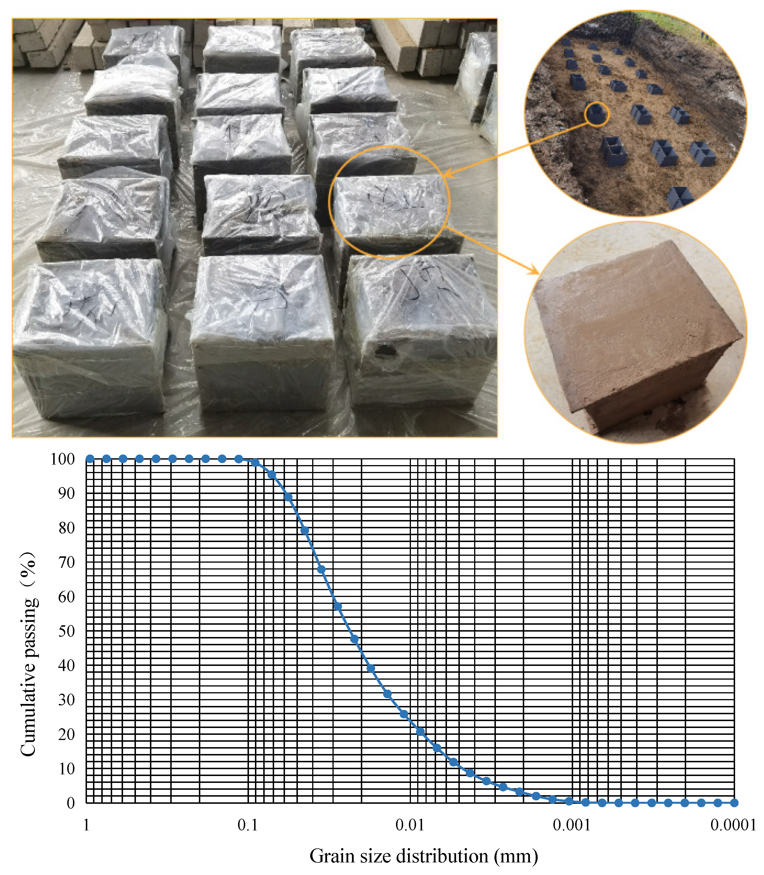
During the test, the soil was taken from a building foundation pit in the south of Changchun City, China. The soil samples were collected using a special soil sampler. The size of the soil sample was 350 mm in height, 300 mm in width and 280 mm in depth. The soil sample extraction process was as follows [28]: first, the soil sampler was placed on the flat surface of the foundation pit; second, a hydraulic equipment was used to press the soil sampler into the foundation pit so that the soil sampler was filled with soil; then, the soil sampler was dug out by an excavator; finally, the soil sample box was wrapped in plastic film to prevent moisture evaporation (as shown in Figure 1). Figure 1 shows the undisturbed soil retrieved from the site and its grain size distribution curve. The soil was low liquid limit clay. As shown in Table 1, the cohesion and internal friction angle of the soil were obtained by triaxial shear test.
2.2. Model Pile
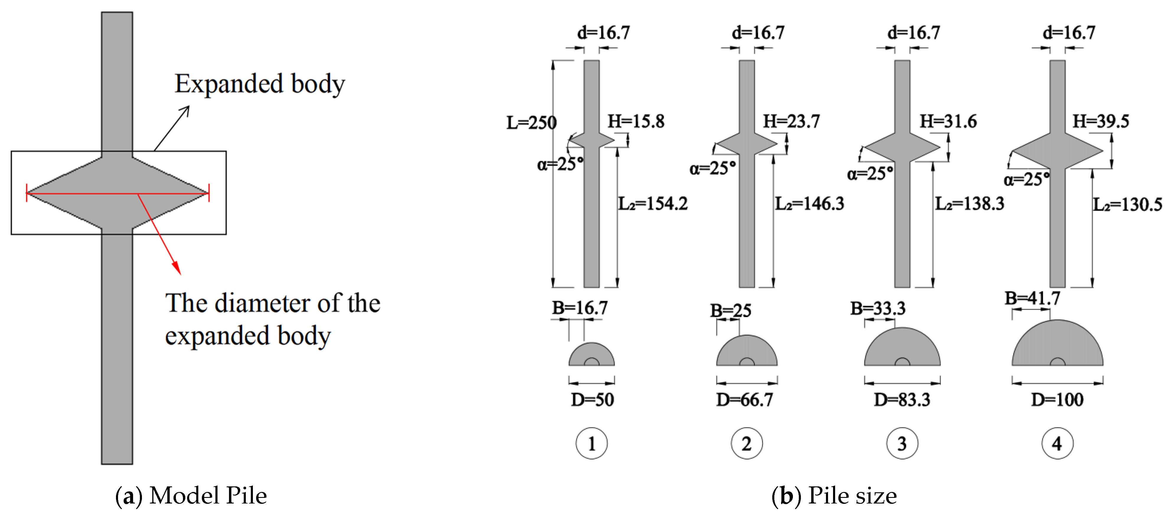
The model pile used in this paper is a steel half-section model pile with a length of 250 mm, a main diameter of 16.7 mm and an expanded body slope angle of 25°. Different diameters of the expanded body were also selected. The sizing diagram is shown in Figure 2, and the parameters of the model pile are shown in Table 2.
2.3. Test Method
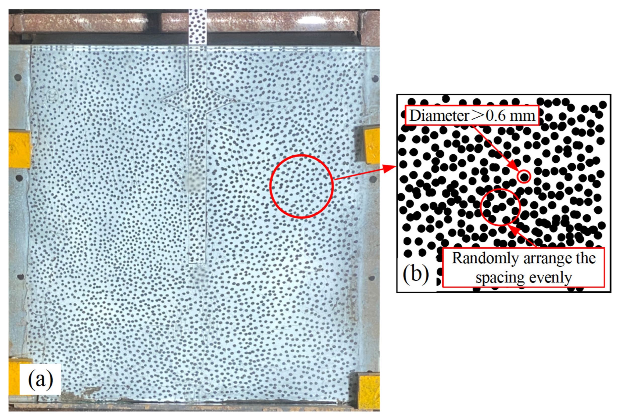
After the surface of the soil was treated flat, the model steel pile was placed in the soil sample. Due to the soil particles being yellow, small soil particles were not apparent. The soil surface was sprayed with white paint to achieve the subsequent digital image processing. After the white paint dried slightly, black speckles with a diameter above 0.6 mm were drawn on the white painted surface as shown in Figure 3. The shooting area in this test was about 300 mm × 300 mm. After the observation surface was fixed with a glass plate, the soil sample box was placed on the loading platform to wait for loading.
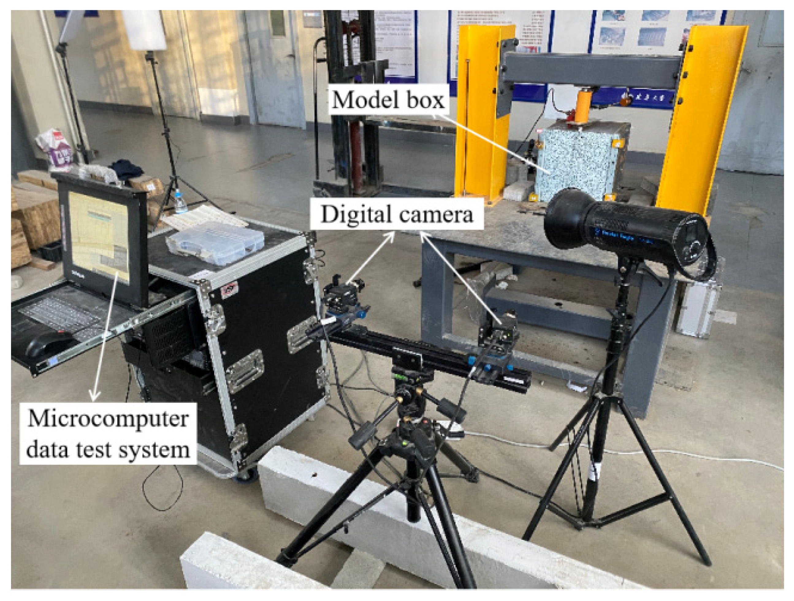
Figure 4 indicates the instruments adopted in the testing, including the loading system and image-collecting systems. The loading system comprised a load platform, reaction rack, ZY bolt tension meter, digital dial indicator (measuring range, 0–50.8 mm), etc. The image-collecting systems utilized were VIC-3D measuring systems supplied by Correlated Solution, which were composed of VIC-3D measuring heads, camera lights and microcomputer test systems. LED-2000 photography lights were arranged in front of the acquisition surface to obtain uniform lighting. During the test, the load value was recorded once for every 0.2 mm settlement of the pile body, and the photography rate is 1 photo/250 ms.
3. Results and Analysis
3.1. Failure Characteristics of Soil around the Pile
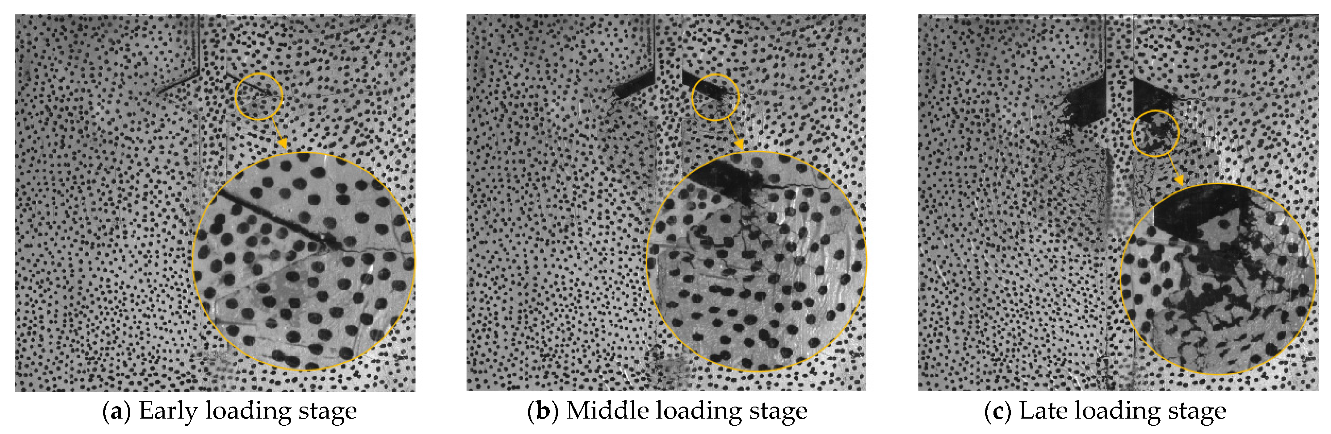
The failure characteristics of the soil surrounding the pile under a load are shown in Figure 5. Taking No. 2 pile as an example, the process is divided into three parts: the early, middle and late loading stages.
Early loading stage (0–0.5 kN): When the load is applied slowly, the soil beneath the expanded body and the pile ends are compressed. Due to the small load, only tiny gaps are generated above the expanded body, as shown in Figure 5a.
Middle loading stage (0.5–1.1 kN): The soil on both sides of the expanded body produces horizontal tension cracks with the increasing load. Subsequently, the radiation range of the tension cracks gradually increases with the increased load and extends along the vertical direction of the lower surface phase of the expanded body. The soil at both ends of the expanded body produces slip, leading to the continuous development of tension cracks. Furthermore, at both ends of the expanded body, a slip line is generated in the direction of about 45° from the main pile, as shown in Figure 5b.
Late loading stage (1.1 kN to the end): This stage is characterized by the soil being punctured, and the soil surrounding the pile cannot provide a stabilized bearing action. As the load continues to increase, many tension cracks appear above the expanded body, and the soil falls off, as shown in Figure 5c. The appearance and development of tension cracks around the expanded body could reduce the restraint of soil around the expanded body and this leads to a reduction in load-bearing capacity of surrounding soil [37].
3.2. Displacement Distribution Characteristics of Soil Surrounding the Pile
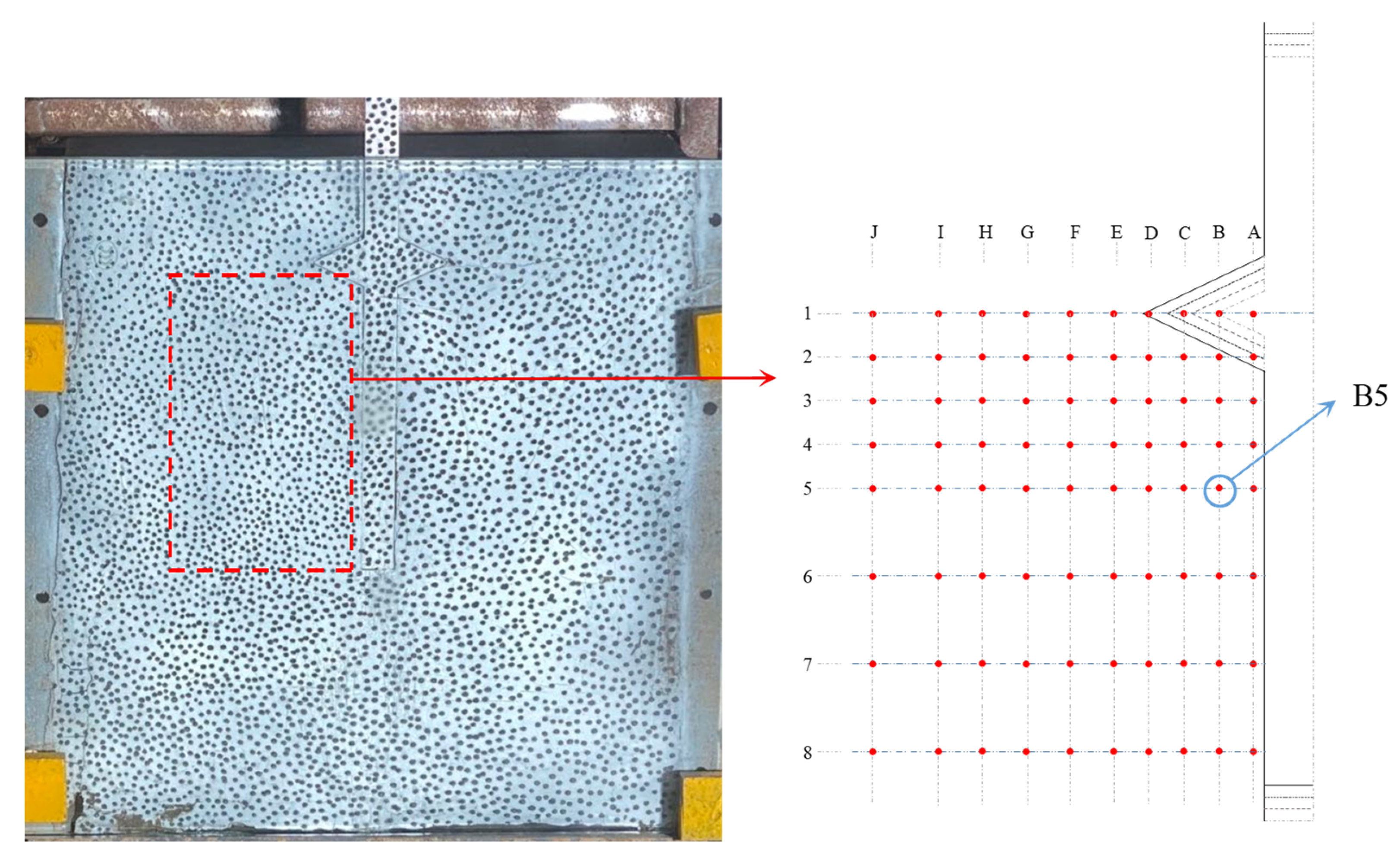
A high-definition digital camera dynamically monitored soil displacement during the loading process. The displacement data of the soil at various positions were extracted using DIC technology. Additionally, the displacement distribution law of the soil surrounding the pile under the load was analyzed. The specific data point distribution is shown in Figure 6. A combination of letters and numbers marks the data points. For example, the B5 point represents the data point in column B (axis B) and the fifth row (row 5). The test assumes that the horizontal displacement to the right and the vertical displacement upwards are positive. As the displacement trend of soil surrounding each pile is similar, this part takes No. 2 pile as an example to analyze.
3.2.1. Displacement Analysis of Soil in the Same Buried Depth
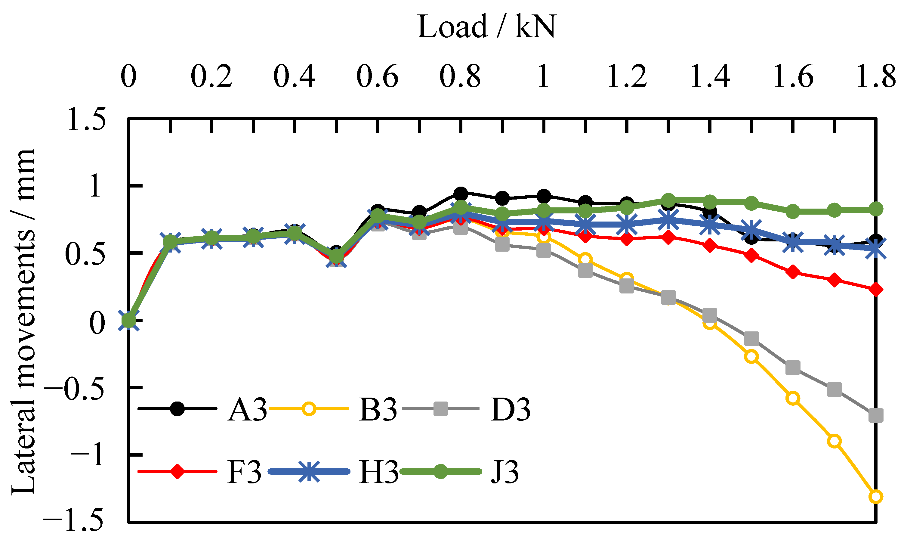
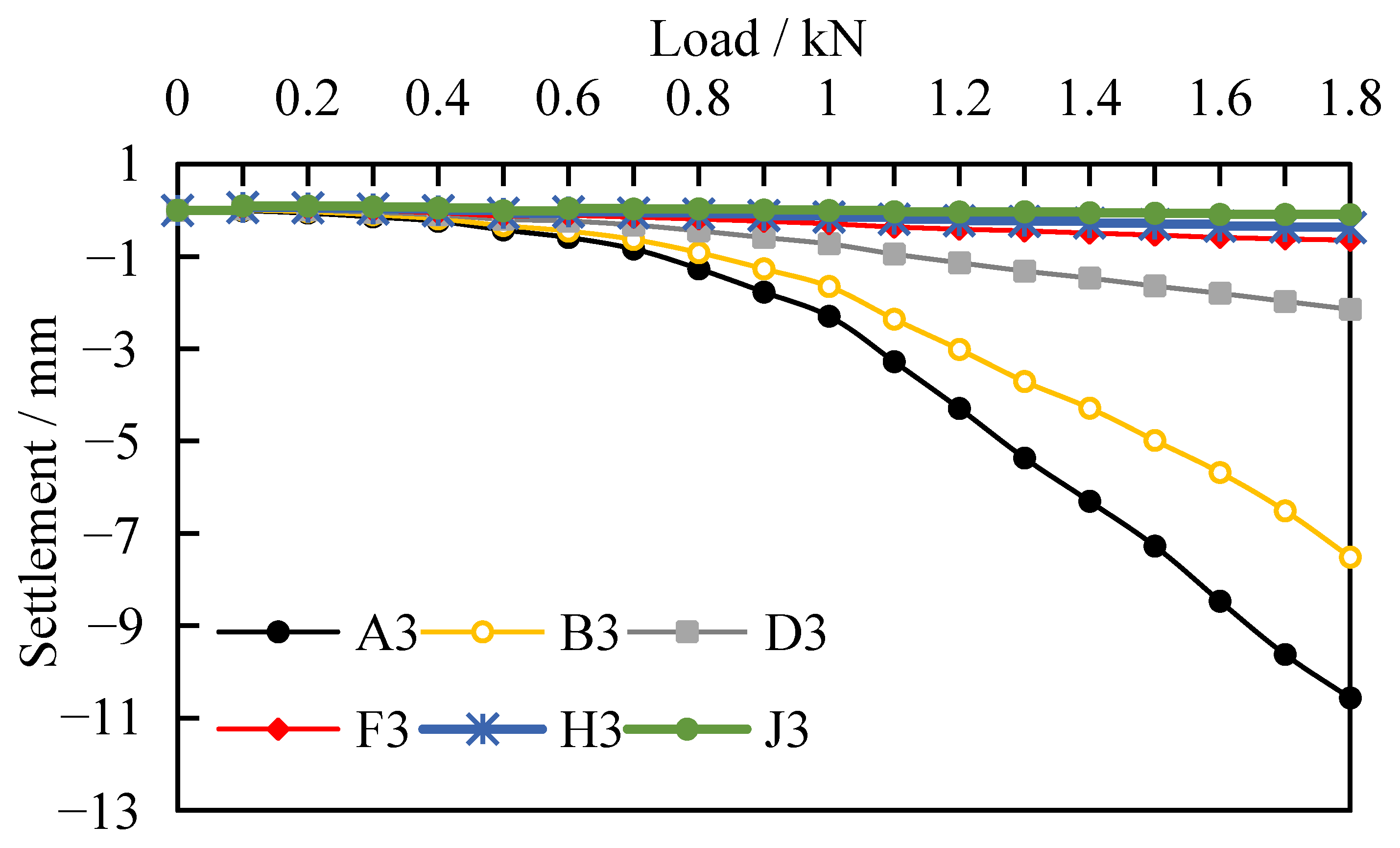
Through DIC technology, the displacement of each point in the same buried depth around the pile under a load was obtained. Figure 7 and Figure 8 are the horizontal and vertical displacement of each point on the third row around No. 2 pile.
As can be seen from Figure 7, the soil in the same buried depth moves horizontally toward the pile body in the initial loading stage, which is likely due to the soil mass below the expanded body being compressed under the load in the initial loading stage. In the middle and late loading periods, the soil near the expanded body generates a horizontal displacement away from the pile body under the load (such as B3, D3, and F3). With the increased load, the horizontal displacement gradually increases, while the horizontal displacement at all points far away from the expanded body (H3 and J3) shows little change. As seen in Figure 8, with the increasing load, the downward displacement of the soil tends to increase as a whole. The farther the soil is from the expanded body, the smaller the vertical displacement. When the load reaches 1.3 kN, the vertical displacement of the soil in A3, B3, D3 and F3 (the four points are, respectively, under the expanded body next to the pile body, below the expanded body, outside the diameter expanded body and far away from the pile) have large differences, which are −5.4, −3.7, −1.1 and −0.45 mm, respectively. This indicates that the influence range of the soil surrounding the pile is mainly below the expanded body.
3.2.2. Displacement Analysis of Soil in Different Buried Depths around the Pile
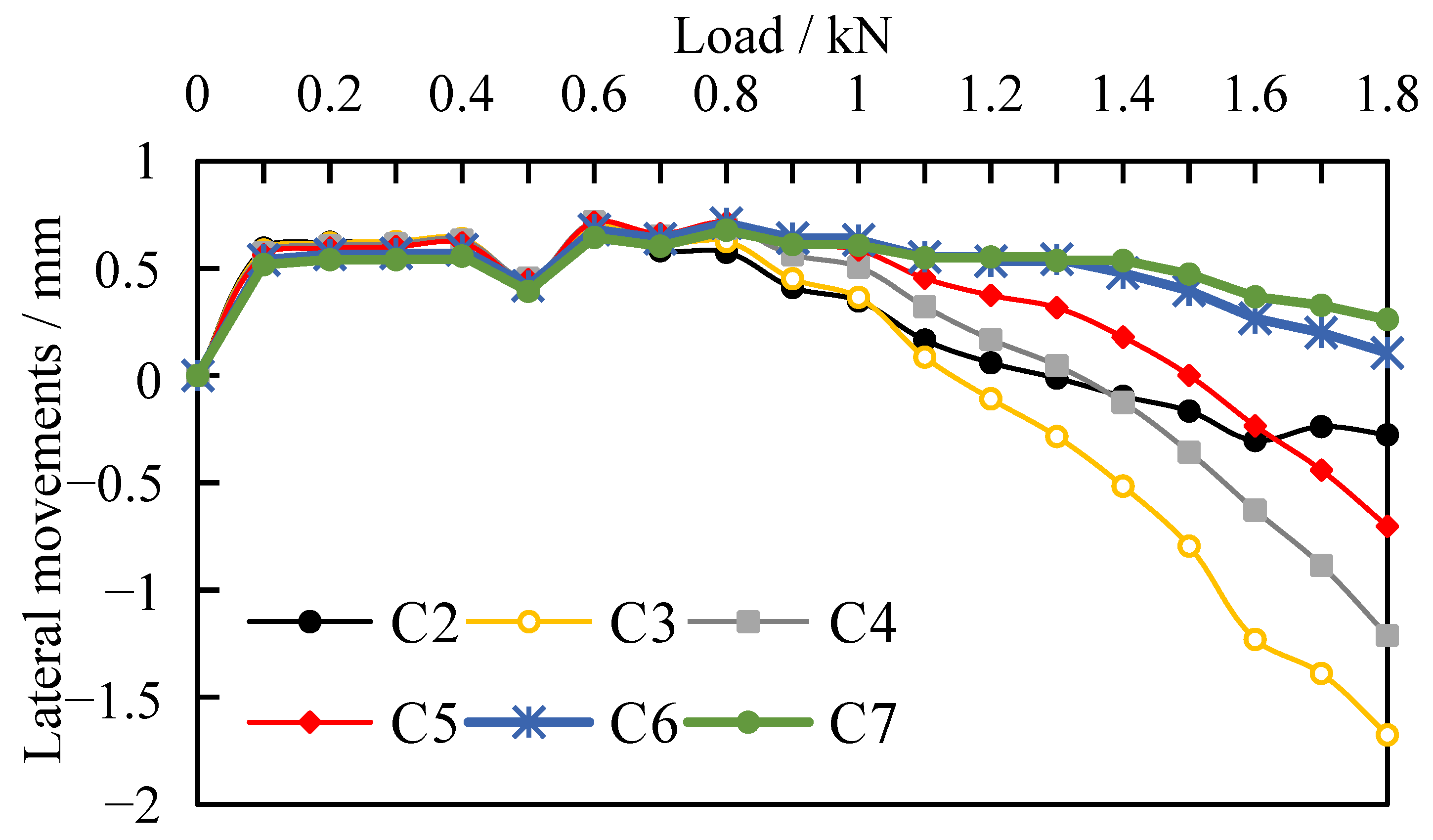
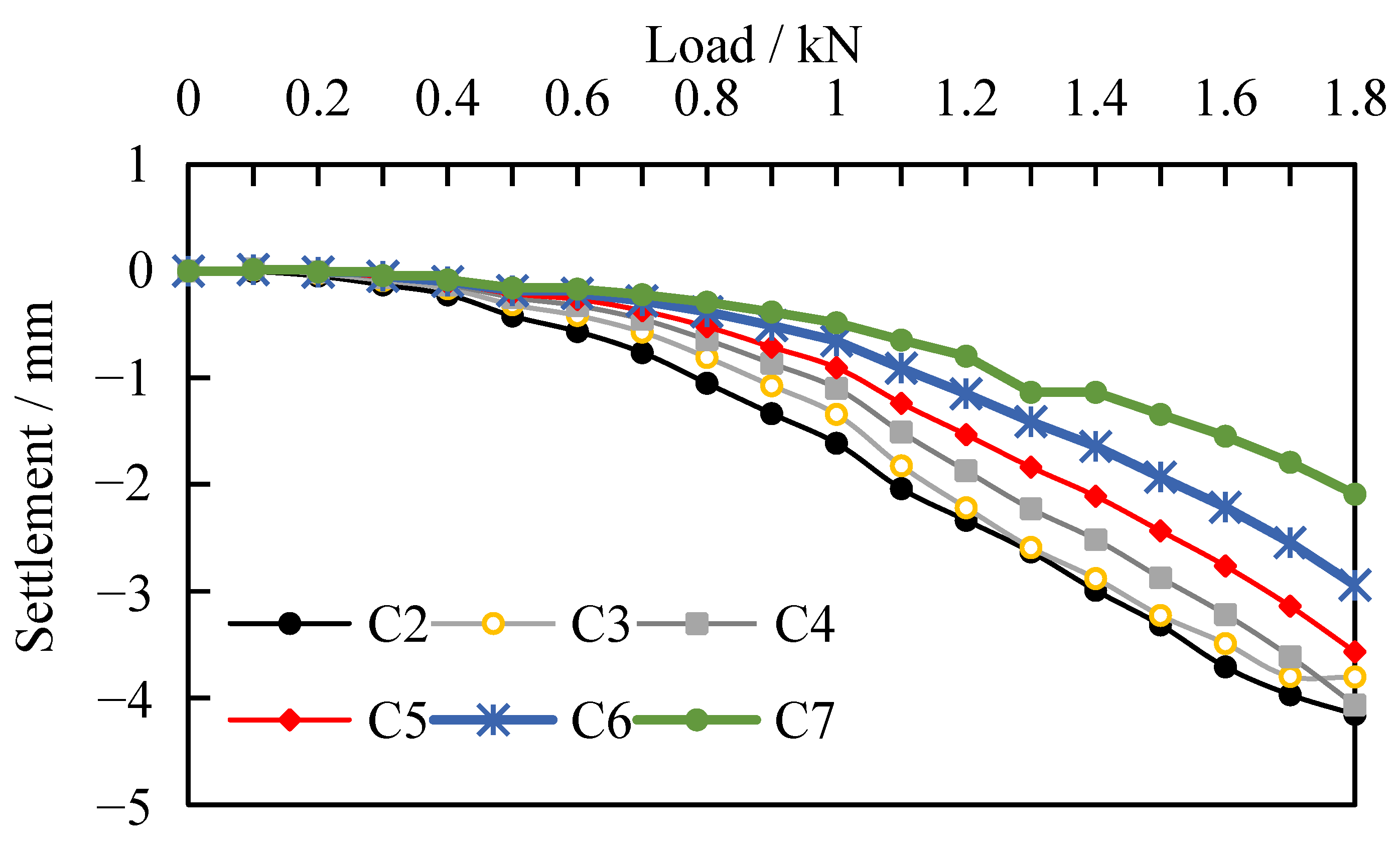
The displacement of each point at different buried depths next to the pile under the load was obtained. The horizontal displacement of each point on the axis C is illustrated in Figure 9, and the vertical displacement of each point on the axis C is illustrated in Figure 10.
As shown in Figure 9, the overall trend of the horizontal displacement at all points of axis C is that the horizontal displacement first moves toward the pile. With increasing burial depth, the horizontal displacement of the soil around the pile reached its maximum (C3 and C4) at a certain distance below the expanded body, showing a “C” shaped distribution [22]. As shown in Figure 10, with the increased load, the vertical displacement generated by each point in different buried depths increases linearly. Still, the increased rate is different at different buried depths. The deeper the buried depth, the smaller the increased displacement rate, indicating that the impact of the load is relatively small. The lateral movements are small but may have an impact on the overall pile behavior if there are adjacent single piles nearby, such as piles in a group, which is more practical and important [38].
3.3. Distribution Characteristics of Displacement Field of Compressed Location
With the increased pile top displacement, the soil surrounding the pile will be displaced accordingly. The downward extrusion of the expanded body will produce a compression zone, the range of which is directly related to the diameter of the expanded body [22].
3.3.1. Distribution Characteristics of the Horizontal Displacement Field
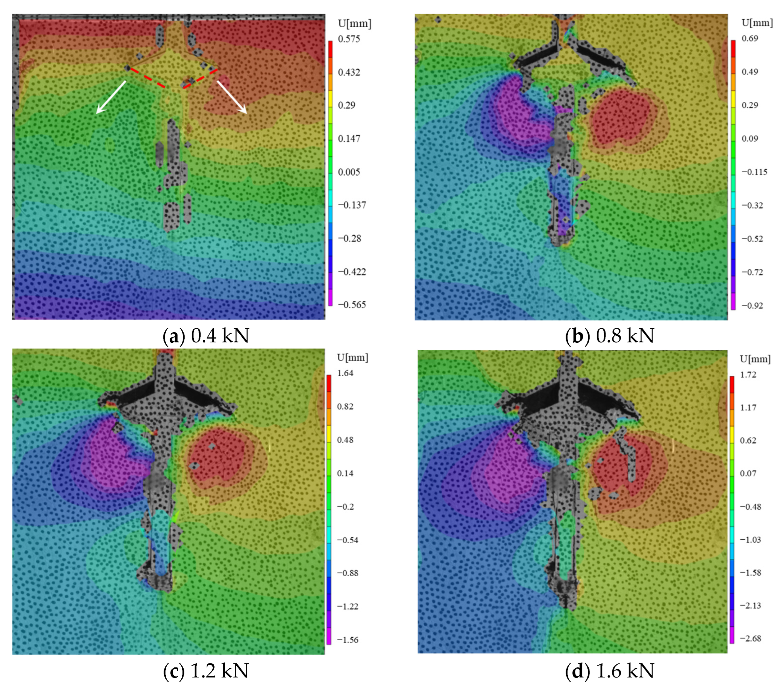
Taking No. 3 pile as an example, the horizontal displacement cloud of the soil surrounding the pile was obtained with the loads of 0.4, 0.8, 1.2 and 1.6 kN, respectively, which is shown in Figure 11. In Figure 11, the positive and negative numbers in the legend represent the movement direction of the soil (the positive number means the soil moves to the right). The vertical center line is manually selected, and there may be errors during the process, which may lead to the difference in the movement data of the soil on the left and right sides.
As shown in Figure 11, the primary horizontal distribution influence area of the soil surrounding the pile under a load is concentrated under the expanded body and on both sides of the main pile. With an increased load, the range develops toward the normal direction of the surface under the expanded body (white arrow direction in Figure 11a). The change in the process is not only the further expansion of the range but also, with the increased load, the displacement of the soil increases.
3.3.2. Vertical Displacement Distribution Characteristics
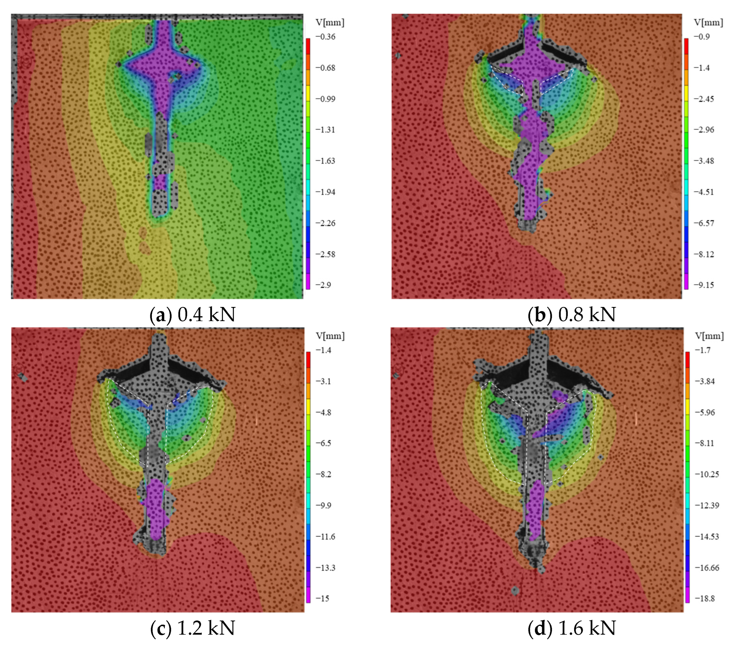
Figure 12 illustrates the vertical displacement cloud of the soil surrounding the pile (No. 3) with the loads of 0.4, 0.8, 1.2 and 1.6 kN, respectively. As shown in Figure 12, the pile will be settled under the load, and the area adjacent to the expanded body and on both sides of the main pile is the main influence range. Unlike the horizontal displacement, with increasing load, the range has no obvious outward expansion in the horizontal direction, and the whole area slowly develops downward along the main pile.
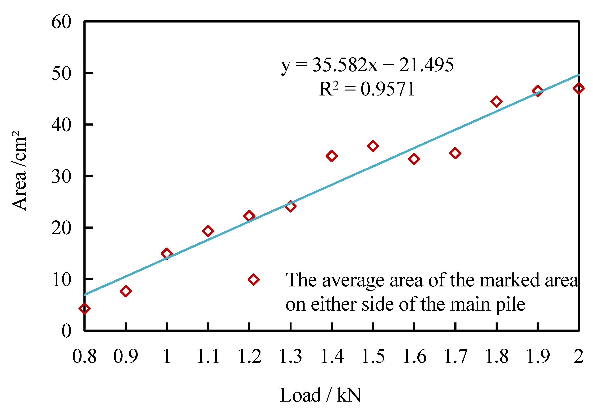
As the load increases, the boundary range under the expanded body in Figure 12 does not increase significantly. However, the displacement increases gradually under different loads. The soil next to the pile with a displacement of more than 6 mm is marked to analyze the influence of the loads on the soil. For example, the settlement range of the soil in Figure 12b is about 6–9 mm, Figure 12c is about 6–15 mm and Figure 12d is about 6–18 mm. The marked area with a load of 0.8–2 kN is processed by CAD 2021, and the area obtained after the average value is added from left to right is shown in Figure 13. As seen in Figure 13, the vertical displacement of soil on both sides of the pile, which is above 6 mm, increases linearly with the increased load.
3.4. Relationship between Compression Region Range and Diameter of the Expanded Body
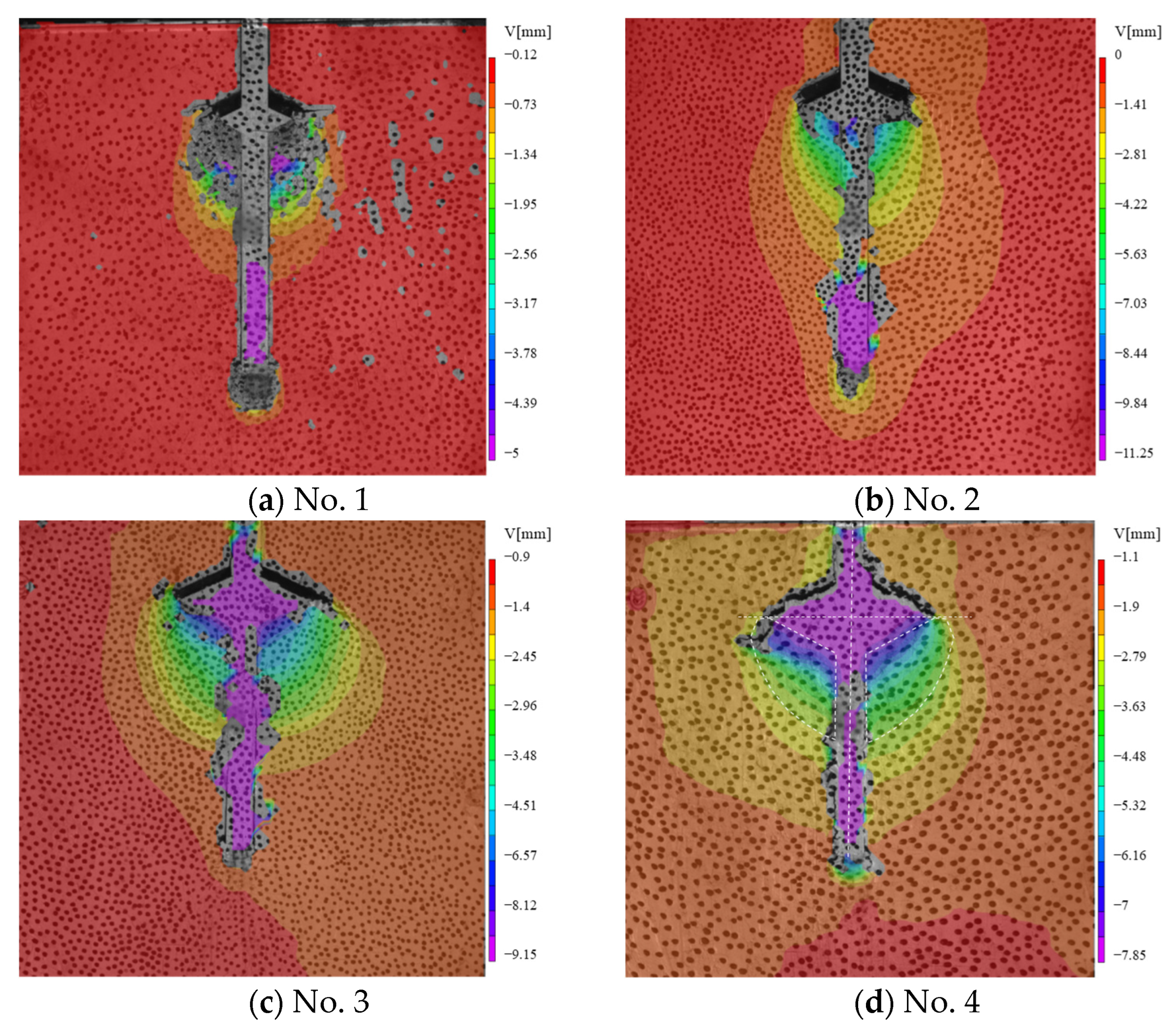
Figure 14 shows the vertical displacement of the soil surrounding the piles (No. 1 to No. 4) when the load is 0.8 kN.
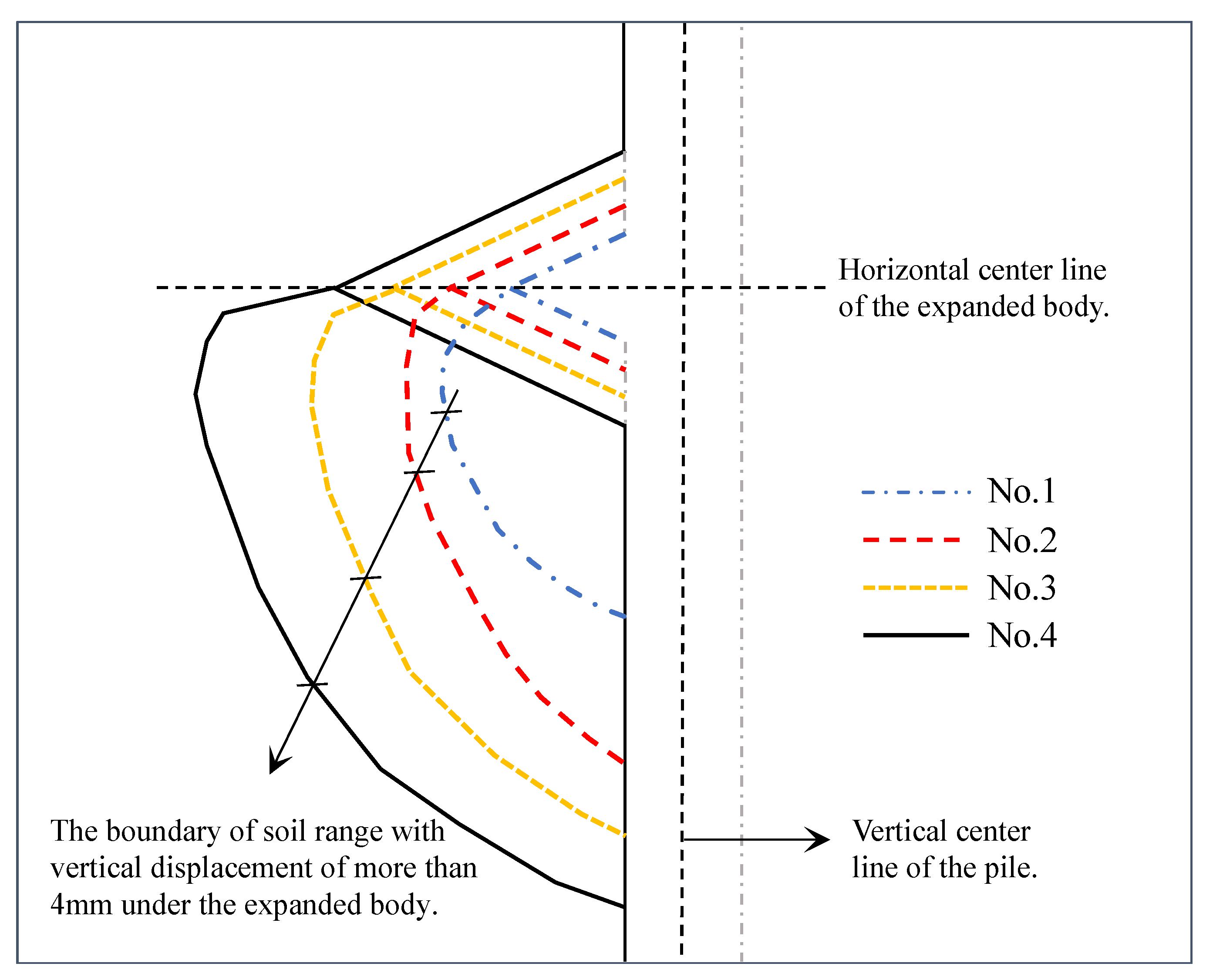
It is shown in Figure 14 that when the load is 0.8 kN, a void is created due to the separation between the expanded body and the upper soil, and the height of the void decreases with the increasing diameter of the expanded body. In Figure 14a, the soil below the expanded body was crushed (including the soil at the bottom), and the main influence area under the expanded body was elliptical. It can be seen from No. 2 to No. 4 pile (Figure 14b,c) that with the increasing diameter of the expanded body, the main influence range develops. The range of a vertical displacement of more than 4 mm is generated under the expanded body. Additionally, the influence range is defined (white mark in Figure 14d) to discuss the influence of the expanded body diameter on the soil next to the pile, as shown in Figure 15.
According to Figure 15, under a load of 0.8 kN, the extrusion soil (vertical displacement above 4 mm) under the expanded body of No.1 to No.4 piles is a half “heart” shape in the unilateral range. The main influence range on the soil is under the expanded body. With an increased load, the influence range of soil gradually expands along the main pile. Under the same load, with the increased diameter of the expanded body, the main influence range also increases.
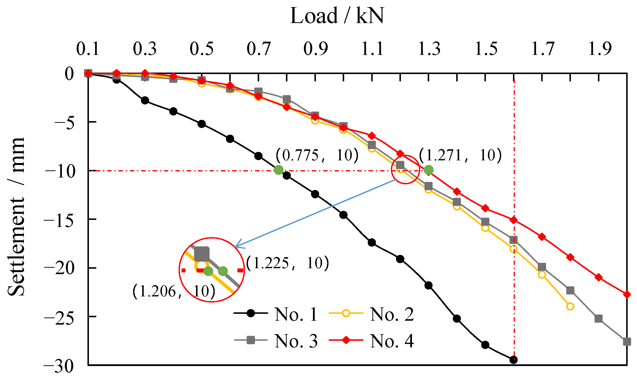
3.5. Relationship between Load and Displacement
Figure 16 shows the load–displacement curves of No. 1, 2, 3 and 4. The vertical displacement of pile tops of each model gradually increases with increasing load. The overall change trend of No. 2, No. 3 and No. 4 piles is similar. During initial loading, the displacement changes with load in a small range, and the slope of the curve is relatively gentle. When the load is increased to 0.7 kN, the slope of the curve becomes steeper. Under the same load (1.6 kN), the order of pile top displacement is No. 1 > No. 2 > No. 3 > No. 4. At the same displacement (10 mm), the bearing capacity of No.1 pile is 0.775 kN, No. 2 pile is 1.206 kN (55.6% higher than No. 1 pile), No. 3 pile is 1.225 kN (58.1% higher than No. 1 pile) and No. 4 pile is 1.271 kN (64% higher than that of No.1 pile). Therefore, increasing the expanded body’s diameter can improve the single pile’s bearing capacity. However, when it exceeds a certain range, the improvement effect is not obvious (such as in No. 2, No. 3 and No. 4 piles).
4. Conclusions
The characteristics of soil displacement distribution surrounding a pile was investigated using indoor model tests. The following conclusions were drawn:
- (1)
- The horizontal displacement of soil at different positions next to the pile has the same trend under the load; the soil first approaches the pile and then deviates from the pile due to the continuous pressure of the expanded body. The vertical displacement of soil next to the pile increases with the increased load. However, it decreases with increased buried depth and distance from the pile;
- (2)
- Under the action of load, the soil on both sides of the expanded body develops horizontal cracks, and the radiation range of the cracks gradually increases with the increased load. There is a region under the expanded body that greatly influences the displacement of the soil surrounding the pile. Notably, the region increases with the increased diameter of the expanded body;
- (3)
- The settlement of the pile mainly affects the soil below the expanded body and on both sides of the main pile. The horizontal influence range mainly develops along the normal direction of the lower surface of the expanded body, and the vertical influence range develops along the main pile. The influence area of the soil surrounding the pile is determined by the different diameters of the expanded body, which is proportional to the diameter of the expanded body;
- (4)
- The bearing capacity of a drill-expanded concrete pile increases with the diameter of expanded body but tends to be stable after reaching a specific value. Therefore, pile spacing, construction factors, economic indicators and other factors should be considered for comprehensive selection in the project.
Author Contributions
Formal analysis, C.Q.; investigation, L.X. and C.Q.; data curation, L.N. and X.D.; writing—original draft preparation, C.Q. and L.X.; writing—review and editing, L.X. and L.N.; supervision, L.X. All authors have read and agreed to the published version of the manuscript.
Funding
This work was supported by the National Natural Science Foundation of China (No. 52008185) and Jilin Provincial Science and Technology Department (No. 20220203063SF).
Data Availability Statement
The data used to support the findings of this study are included in the article.
Conflicts of Interest
The authors declare that they have no conflicts of interest regarding the publication of this paper.
References
- Lv, Y.R.; Liu, H.L.; Ding, X.M.; Kong, G.Q. Field tests on bearing characteristics of X-Section pile composite foundation. J. Perform. Constr. Fac. 2012, 26, 180–189. [Google Scholar] [CrossRef]
- Yang, J.; Tham, L.G.; Lee, P.K.; Yu, F. Observed performance of long steel h-piles jacked into sandy soils. J. Geotech. Geoenviron. 2006, 132, 24–35. [Google Scholar] [CrossRef] [Green Version]
- Naggar, M.H.E.; Sakr, M. Evaluation of axial performance of tapered piles from centrifuge tests. Can. Geotech. J. 2000, 37, 1295–1308. [Google Scholar] [CrossRef]
- Fattah, M.Y.; Al-Soudani, W.H.S. Bearing capacity of closed and open ended pipe piles installed in loose sand with emphasis on soil plug. Indian J. Mar. Sci. 2016, 45, 703–724. [Google Scholar]
- Honda, T.; Hirai, Y.; Sato, E. Uplift capacity of belled and multi-belled piles in dense sand. Soils Found. 2011, 51, 483–496. [Google Scholar] [CrossRef] [Green Version]
- Wang, Z.Q.; Liu, H.L.; Zhang, M.X.; Yuan, J.; Yong, J. Full scale model tests on vertical bearing characteristics of cast-inplace X-section pile. Chin. J. Geotech. Eng. 2010, 36, 903–907. [Google Scholar]
- Ren, L.W.; Guo, W.D.; Yang, Q.W. Analysis on bearing performance of Y-shaped piles under compressive and tensile loading. Proc. Inst. Civ. Eng.-Geotech. Eng. 2020, 173, 58–69. [Google Scholar] [CrossRef]
- Zhou, Y.; Xiao, S.G.; Xu, J.; Hu, Y.Y. Model test on vertical bearing capacity of variable cross-section thread piles. Rock Soil Mech. 2017, 38, 747–783. [Google Scholar]
- Qian, Y.M.; Zhang, J.Y.; Wang, R.Z.; Tian, W. Experimental Study on Effect of plate and plate end forms on pull-out failure of concrete expanded plate pile applied in ocean engineering. J. Costal Res. 2021, 111, 93–100. [Google Scholar] [CrossRef]
- Dieu, T.B. Prediction of Pullout Behavior of Belled Piles through Various Machine Learning Modelling Techniques. J. Sens. 2019, 19, 3678. [Google Scholar]
- Ren, L.W.; Yang, Q.W.; Kong, G.Q.; Dun, Z.L.; Wang, X.Y. Model tests on Y-Shaped piles under compressive and lateral loading in saturated sand. Geofluids 2021, 2021, 6978602. [Google Scholar] [CrossRef]
- Zhou, J.; Huang, X.; Zhang, J.; Wei, L.; Yuan, J. Experimental investigation of the uplift and lateral bearing capacity of root piles. Soil Mech. Found. Eng. 2021, 57, 473–479. [Google Scholar] [CrossRef]
- Zhou, H.; Yuan, J.R.; Liu, H.L. A general analytical solution for lateral soil response of non-circular cross-sectional pile segmen. Appl. Math. Model. 2019, 71, 601–631. [Google Scholar] [CrossRef]
- Zhou, H. Complex variable solution for boundary value problem with X-shaped cavity in plane elasticity and its application. Appl. Math. Mech. 2017, 38, 1329–1346. [Google Scholar] [CrossRef]
- Liu, F.; Yi, J.T.; Dong, J.J.; Zhou, H. Numerical modelling of the long-term effects of XCC piling in fine-grained soil. Geomech. Eng. 2021, 26, 27–40. [Google Scholar]
- Shabanpour, A.; Ghazavi, M. Centrifuge tests on axially loaded tapered piles with different cross-sections under compressive and tensile loading. Can. Geotech. J. 2022, 59, 1205–1214. [Google Scholar] [CrossRef]
- Fang, T.; Huang, M.; Tang, K. Cross-section piles in transparent soil under different dimensional conditions subjected to vertical load: An experimental study. Arab. J. Geosci. 2020, 13, 1133. [Google Scholar] [CrossRef]
- Qi, C.G.; Liu, G.B.; Wang, Y.; Deng, Y.B. Theoretical study on setup of expanded-base pile considering cavity contraction. J. Cent. South Univ. 2015, 22, 4355–4365. [Google Scholar] [CrossRef]
- Fenu, L. Buckling Analysis of Piles in Multi-Layered Soils. J. Appl. Sci. 2021, 11, 10624. [Google Scholar] [CrossRef]
- Michele, P.A.; Lorella, M. Analysis of the Behaviour of Very Slender Piles: Focus on the Ultimate Load. J. Int. J. Civ. Eng. 2021, 19, 145–153. [Google Scholar]
- Alshawabkeh, Y.M. Lateral buckling capacity of steel H-piles supporting integral abutment bridges (IABs). J. Struct. 2023, 50, 896–907. [Google Scholar] [CrossRef]
- Zhang, Q.Q.; Chen, Z.G.; Li, J.L.; Liu, S.W. Pressure-cast-in-situ pile with spray-expanded frustum: Construction equipment and process. J. Constr. Eng. Manag. 2021, 146, 06021002. [Google Scholar] [CrossRef]
- Qian, Y.M.; Zhou, T.T.; Tian, W. Anti-overturning bearing capacity of rigid and flexible concrete expanded piles subjected to horizontal load. Adv. Civ. Eng. 2020, 2020, 4901069. [Google Scholar] [CrossRef]
- Qian, Y.M.; Liu, J.L.; Wang, R.Z.; Jin, Y.J. Experimental study on influence of disc position on soil failure state of expanded pile under horizontal force in oceanographic engineering. J. Coast. Res. 2020, 108, 274–282. [Google Scholar] [CrossRef]
- Qian, Y.M.; Liu, H.B.; Yin, X.S.; Jin, Y.J. Computer analysis of influence of moisture content of the fine-silty sand for the CEP pile applied for oceanographic engineering under vertical tensile. J. Coast. Res. 2019, 94, 362–366. [Google Scholar] [CrossRef]
- Xu, L.N.; Deng, H.Y.; Zheng, J.J.; Qian, Y.M.; Niu, L. Experimental study on influence of diameter of expanded body on soil around drilled-expanded concrete pile. J. Hunan Univ. (Nat. Sci.) 2022, 49, 222–234. [Google Scholar]
- Qi, C.G.; Iskander, M.; Omidvar, M. Soil deformations during casing jacking and extraction of expanded-shoe piles, using model tests. Geotech. Geol. Eng. 2017, 35, 809–826. [Google Scholar] [CrossRef]
- Sato, T.; Onda, K.; Otani, J. Development of a new loading test apparatus for microfocus X-ray CT and its application to the investigation of soil behavior surrounding driven open-section piles. Soil Found. 2018, 58, 776–785. [Google Scholar] [CrossRef]
- Arshad, M.I.; Tehrani, F.S.; Prezzi, M.; Salgado, R. Experimental study of cone penetration in silica sand using digital image correlation. Géotechnique 2014, 64, 551–569. [Google Scholar] [CrossRef]
- Tovar-Valencia, R.D.; Galvis-Castro, A.; Salgado, R.; Prezzi, M. Effect of surface roughness on the shaft resistance of displacement model piles in sand. J. Geotech. Geoenviron. 2018, 144, 04017120. [Google Scholar] [CrossRef]
- Kong, G.Q.; Cao, Z.H.; Zhou, H.; Sun, X.J. Analysis of piles under oblique pullout load using transparent-soil models. Geotech. Test J. 2015, 38, 725–738. [Google Scholar] [CrossRef]
- Xu, L.N.; Deng, H.Y.; Niu, L.; Qian, Y.M.; Song, D.H. Study on soil displacement fields around the expanded body of drill-expanded concrete piles based on DIC technique. Appl. Sci. 2021, 11, 9097. [Google Scholar] [CrossRef]
- Doreau-Malioche, J. Characterising processes at sand-pile interface using digital image analysis and X-ray CT. Geotech. Lett. 2019, 9, 1–9. [Google Scholar] [CrossRef]
- Yuan, B.X. Experimental study of displacement field of layered soils surrounding laterally loaded pile based on Transparent Soil. J. Soils Sediments 2021, 21, 3072–3083. [Google Scholar] [CrossRef]
- Yuan, B.X. Investigation of 3D deformation of transparent soil around a laterally loaded pile based on a hydraulic gradient model test. J. Build. Eng. 2020, 28, 1010124. [Google Scholar] [CrossRef]
- Yuan, B.X. Full 3D displacement measuring system for 3D displacement field of soil around a laterally loaded pile in transparent soil. Int. J. Geomech. 2019, 19, 04019028. [Google Scholar] [CrossRef]
- Leung, C.F.; Ong, D.E.; Chow, Y.K. Pile Behavior Due to Excavation-Induced Soil Movement in Clay. II: Collapsed Wall. J. Geotech. Geoenviron. Eng. 2006, 132, 45–53. [Google Scholar] [CrossRef]
- Ong, D.E.; Leung, C.F.; Chow, Y. Piles subject to excavation-induced soil movement in clay. In Proceedings of the 13th European Conference on Soil Mechanics and Geotechnical Engineering, Prague, Czech Republic, 25–28 August 2003. [Google Scholar]
Figure 1.
Undisturbed soil retrieved from the site and its grain size distribution curve.

Figure 2.
Schematic diagram of the model pile size (Unit: mm).

Figure 3.
Photo of soil collection surface: (a) soil surface with speckles; (b) enlarged speckle diagram.
Figure 3.
Photo of soil collection surface: (a) soil surface with speckles; (b) enlarged speckle diagram.

Figure 4.
Test instrument.

Figure 5.
Failure process of soil surrounding the pile.

Figure 6.
Distribution of data points.

Figure 7.
Horizontal displacement of each point on Axis 3 (No. 2 pile).

Figure 8.
Vertical displacement of each point on Axis 3 (No. 2 pile).

Figure 9.
The horizontal displacement of each point on the C-axis.

Figure 10.
The vertical displacement of each point on the C-axis.

Figure 11.
Horizontal displacement cloud image.

Figure 12.
Vertical displacement cloud image.

Figure 13.
The average area of marked areas on both sides of the pile under different loads.

Figure 14.
The vertical displacement of soil surrounding the pile (load: 0.8 kN).

Figure 15.
Schematic diagram of the range of vertical displacement above 4 mm around the pile with different expanded diameters.
Figure 15.
Schematic diagram of the range of vertical displacement above 4 mm around the pile with different expanded diameters.

Figure 16.
Load–displacement curve.


Table 1.
Basic parameters of undisturbed soil.
| Density (g/cm3) | Moisture Content (%) | Liquid Limit (%) | Plastic Limit (%) | Cohesion (kPa) | Angle of Internal Friction (°) | Elastic Modulus (MPa) |
|---|---|---|---|---|---|---|
| 1.9 | 23.6 | 38.7 | 22.7 | 21.1 | 14.5 | 6.1 |
Table 2.
The parameters of the model pile.
| Parameters | 1 | 2 | 3 | 4 |
|---|---|---|---|---|
| Diameter of the expanded body, D (mm) | 50 | 66.7 | 83.3 | 100 |
| Height of the expanded body, H (mm) | 15.8 | 23.7 | 31.6 | 39.5 |
| Slope angle of the expanded body, α (°) | 25 | 25 | 25 | 25 |
| Length of overhang, B (mm) | 16.7 | 25 | 33.3 | 41.7 |
| The length of straight pile under the expanded body, L2 (mm) | 154.2 | 146.3 | 138.3 | 130.5 |
Disclaimer/Publisher’s Note: The statements, opinions and data contained in all publications are solely those of the individual author(s) and contributor(s) and not of MDPI and/or the editor(s). MDPI and/or the editor(s) disclaim responsibility for any injury to people or property resulting from any ideas, methods, instructions or products referred to in the content. |
© 2023 by the authors. Licensee MDPI, Basel, Switzerland. This article is an open access article distributed under the terms and conditions of the Creative Commons Attribution (CC BY) license (https://creativecommons.org/licenses/by/4.0/).
Share and Cite
MDPI and ACS Style
Xu, L.; Qi, C.; Niu, L.; Ding, X. Effect of Expanded Body Diameter on the Soil Surrounding a Pile Based on the Half-Face Pile Model Test of Undisturbed Soil. Buildings 2023, 13, 951. https://doi.org/10.3390/buildings13040951
AMA Style
Xu L, Qi C, Niu L, Ding X. Effect of Expanded Body Diameter on the Soil Surrounding a Pile Based on the Half-Face Pile Model Test of Undisturbed Soil. Buildings. 2023; 13(4):951. https://doi.org/10.3390/buildings13040951
Chicago/Turabian StyleXu, Lina, Chenhui Qi, Lei Niu, and Xu Ding. 2023. "Effect of Expanded Body Diameter on the Soil Surrounding a Pile Based on the Half-Face Pile Model Test of Undisturbed Soil" Buildings 13, no. 4: 951. https://doi.org/10.3390/buildings13040951
Note that from the first issue of 2016, this journal uses article numbers instead of page numbers. See further details here.