
In Situ Concrete Bridge Strengthening Using Ductile Activated NSMR CFRP System


Department of Built Environment, University of Aalborg, 9220 Aalborg, Denmark
*
Author to whom correspondence should be addressed.
Buildings 2022, 12(12), 2244; https://doi.org/10.3390/buildings12122244
Submission received: 25 November 2022
/
Revised: 9 December 2022
/
Accepted: 12 December 2022
/
Published: 16 December 2022
(This article belongs to the Special Issue Advanced Composite Materials for Structure Strengthening and Resilience Improving)
Abstract
:Novel and complex structural solutions are often challenging to introduce in the building industry since they may provide unconventional and less verified behavior combined with several novel and unique failure modes. A desired safety level may be difficult to verify due to the lack of knowledge related to failure modes and their variation. This study introduces a method that may provide a first step toward addressing such challenges. Five laboratory tests were done on a novel ductile response-controlled anchor system used for prestressed CFRP NSMR strengthening. These results were used as a basis for further implementation in a pilot project where an in situ cast concrete bridge was strengthened with the developed system. A particular focus was dedicated to the capability of the designed system response to provide a consistent load/deformation curve, yielding threshold, and yielding regime. The novel system enabled response tailoring to the specific pilot project. Installation and prestressing procedure worked as desired, where losses in the fully prestressed system, after three weeks, were approximately 0.2 to 1.6 kN (0.2–1.3 mm). In situ proof loading of all strengthening systems (20 anchor systems) was done to eliminate any possible failure modes below the proof-loading level. It was performed with no signs of distress.
1. Introduction
Carbon fiber reinforced polymers (CFRP) used as near surface mounted reinforcement (NSMR) have been used as a mean to strengthen structures for several decades [1,2,3,4,5,6,7,8,9,10]. CFRP has excellent corrosion resistance, a weight that is 20% of steel, and tensile strength, which is approximately five times higher than for steel reinforcement. The material thus seems excellent for exterior structural reinforcing of existing concrete structures. Epoxy agents are typically used for the adhesive bond between the concrete structure to be strengthened and the CFRP; this may result in utilization from 0.6–0.9 of the ultimate CFRP rupture strain [11]. The reduced utilization is dedicated to premature failure modes which initiate in the concrete, such as intermediate crack (IC) de-bonding [12,13,14,15,16,17] and concrete cover separation [9,18,19]. To utilize the material further, pre-stressed CFRP plates, sheet, and wrap systems were used and researched during recent decades [20,21,22,23,24,25]. However, only a few systems are commercially available, and effective pre-stressed NSMR CFRP strengthening systems seems non-existent. Some reasons for the relatively limited use may be due to challenges related to the anchoring of the anisotropic and brittle material, as well as reluctance toward fiber reinforced polymer (FRP) creep rupture [26,27,28]. CFRP has been shown to be the most robust FRP material against creep rupture, whereas other materials such as Glass-FRP, Aramid-FRP, and Basalt-FRP seem more susceptible in this regard [29]. One of the keys to providing a cost-efficient system may be a well-defined and controlled pre-stressing of CFRP materials in combination with an efficient mounting procedure.
During the last decade, mechanical anchoring and pre-stressing of NSMR CFRP materials has been researched to address some of the presented challenges [30,31,32,33]. The mechanical anchorage is an essential and complex element of the CFRP strengthening system, since it has to account for the anisotropic and brittle properties of the CFRP material [34,35,36,37,38,39]. Some of the most well-known premature brittle failure modes of mechanical anchor systems are CFRP crushing, power and soft slip, cutting of fibers, and bending of fibers [40]. The highest tensile utilization of the CFRP is typically experienced at fiber failure and power slip. It is often seen that only small changes in the controlled stress transfer in the anchor can cause a change of failure mode. As also seen from conventional CFRP strengthening systems, novel pre-stressed CFRP strengthening solutions present an increased number of potentially new failure modes, and when strengthening concrete structures, these must be added to the known failure modes of such structures. This is a typical side effect when developing novel structural systems, where multiple new failure modes may initiate under laboratory and in situ conditions. The outcome is thus an increase of complexity in the capacity analysis, as well as in the safety level assessment.
In the study of [41], where concrete T-section beams were strengthened with an earlier version of the novel CFRP NSMR strengthening system applied in this paper, significant utilization of the CFRP material was achieved with tensile capacities up to 3300 MPa (εfu ≈ 0.02). However, open discussions are still ongoing regarding an acceptable failure strain magnitude, failure modes, and related failure warning. Because of the CFRP material’s reduced ductility compared to steel, which is even more amplified when inducing a pre-stressing strain, it seemed desirable to develop a CFRP strengthening system that can provide a high ductility threshold combined with complete response control. The experimental studies on T-section beams were supported through numerical studies [42].
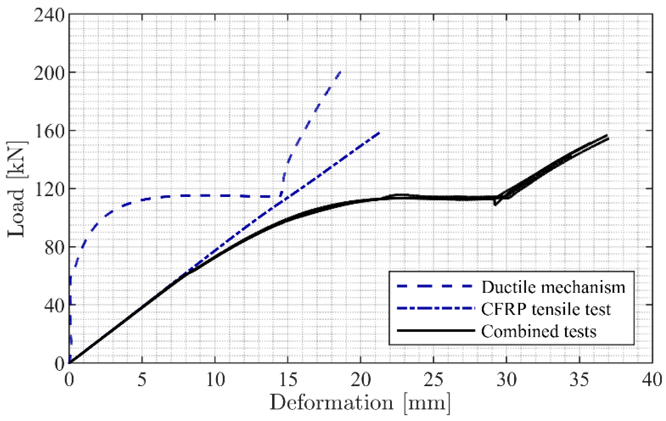
To reduce the number of failure modes and to enable increased control of the anchor behavior, a ductile response-controlled enclosure wedge (EW) CFRP anchor system was developed [43]. Ductility was introduced by coupling the anchor with a component (the ductile mechanism) which has a tailored ductile behavior. Figure 1 shows the separate response curves of the CFRP anchor and the ductile mechanism, along with the curves of a series of combined tests (EW CFRP anchor and ductile mechanism). The ductile unit (mechanism) enables control of the CFRP anchor and thus the strengthening system response. In addition, it can be tailored to provide a desired response combined with a significant ductility fitting to the existing structure.
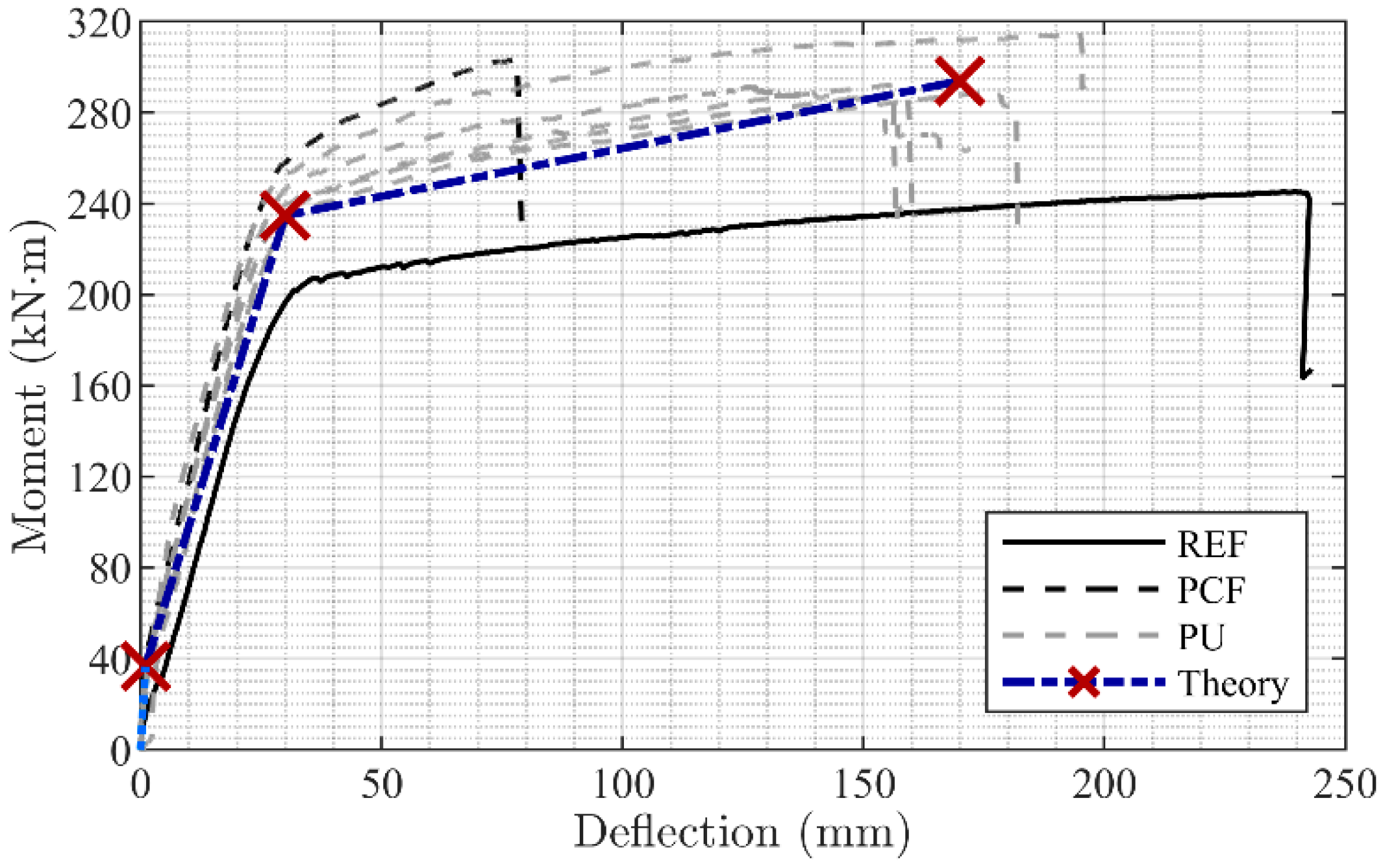
The effectiveness of the system for strengthening purposes was demonstrated through strengthening of concrete T-section beams [44,45]. It is seen from Figure 2 that the system seemed to work as desired, and that significant ductility was gained. “REF” represents the un-strengthened concrete beam with full ductile behavior. “PCF” represents a beam strengthened with the CFRP anchor system bonded with epoxy resin and not including the ductile mechanism; this beam shows increased capacity but reduced ductility. “PU” represents beams strengthened with the ductile response-controlled EW CFRP anchor system and bonded, as NSMR, with a flexible adhesive. It is seen that these beams exhibit ductile behavior near to the un-strengthened reference beam. In addition, the critical failure mode was also shown to be concrete crushing, not system failure, thus preventing additional novel failure modes from occurring.
The basic reliability requirements for such a novel strengthening system are generally that the resistance/load-bearing capacity should not be smaller than the relevant load effect with a probability of failure corresponding to the reliability level required by the design codes and that the failure mode should be ductile thus providing a failure with warning. If the Design Value Format method is used as the basis for the partial factors, then the reliability requirement can be established by only considering the resistance [46]. If several failure modes may be triggered, then the reliability requirements should be satisfied for all of these. However, ensuring this requirement requires evaluation of all unique failure modes of a novel structural element or joint to be mounted in situ and may thus be very costly. In addition, it may often be uncertain if a failure mode is governing when applied to a real structure with additional failure modes unless the response is very controlled.
Scope and Research Questions
This paper provides research concerning a novel ductile response-controlled NSMR CFRP strengthening system. The system was tested as an assembled and complete anchor system under laboratory conditions and was finally applied for strengthening of an in situ bridge. The laboratory test procedure was combined with a probabilistic analysis to provide a safety assessment, which is rarely seen in such studies. In this regard, reliability relates to the load-bearing capacity and obtaining a ductile failure mode (with warning), which is the main objective. The study also includes a probabilistic model for use with the laboratory tests and in situ proof-loading of anchors to verify that a sufficient reliability level is present, concerning the load-bearing capacity. The requirement that a ductile failure mode is obtained is in this paper demonstrated by laboratory tests. A reliability-based assessment may thus be performed by system reliability modeling, which will be presented in more detail in a forthcoming paper. Consequently, the reliability assessment in this paper is based on the reliability principles in the Eurocodes, especially EN1990, Annex C and D [46], ISO 2394 [47], and the JCSS Probabilistic Model Code [48]. With a basis in the ductile behavior, it is hypothesized that:
- The developed ductile strengthening system is applicable for fast and efficient in situ installation.
- Laboratory testing of the assembled and complete CFRP anchorage system will provide high accuracy and thus a low safety factor due to a consistent response and yielding thresholds.
- Proof loading can be used to validate that all other ultimate failure modes from a theoretical safety assessment can be disregarded.
It is thus the aim to answer the following research questions:
- Does the novel activated CFRP system provide a controlled response with warning and consistent yielding thresholds?
- Can the obtained yielding threshold be used as a capacity threshold?
- Can laboratory testing ensure results that provide a basis for validating the required reliability level?
- How can an in situ proof-loading procedure support further validation of the system resistance and reliability?
2. Bridge Pilot Project
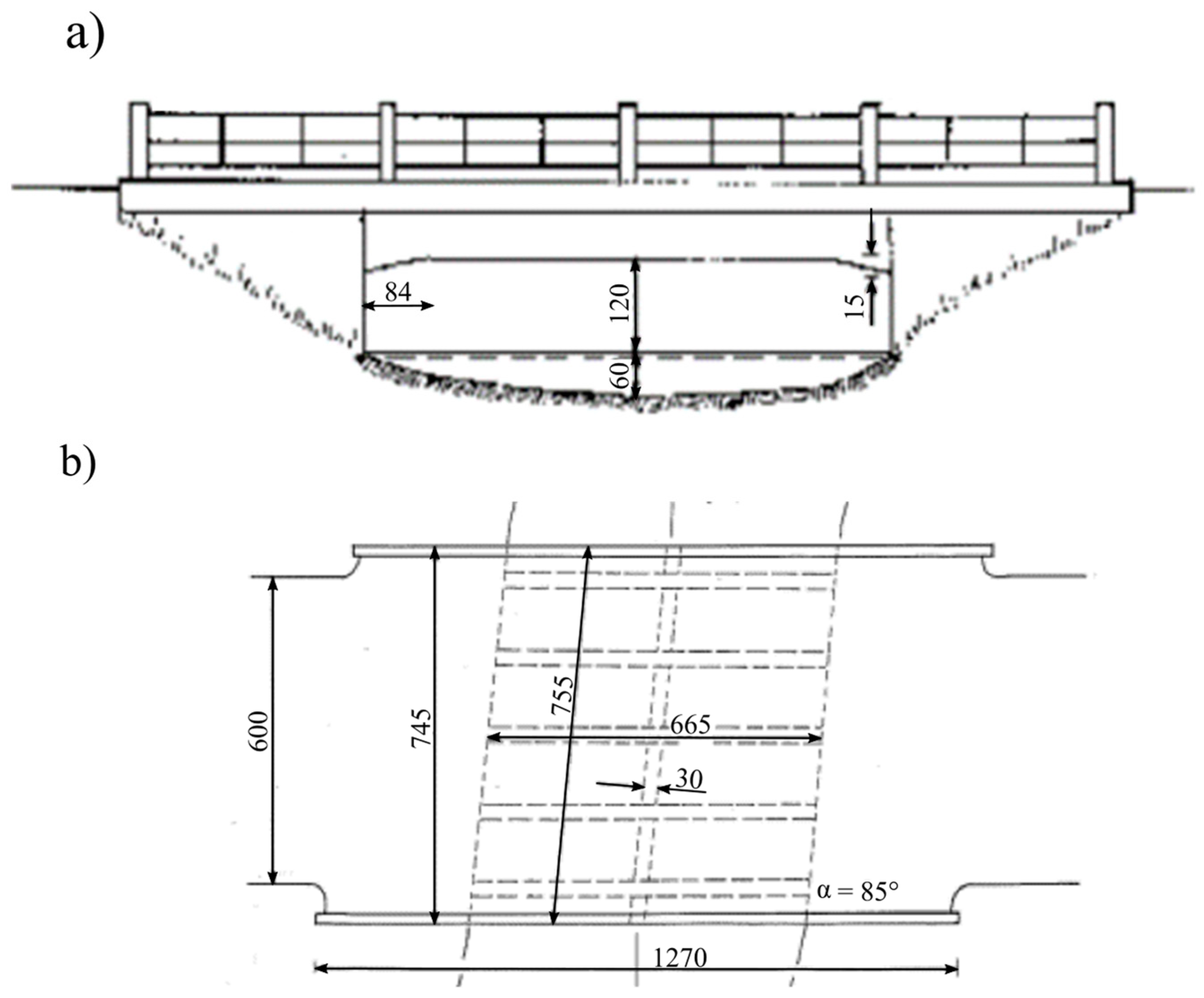
The specific configuration of the CFRP strengthening system presented in this paper was designed to strengthen a bridge in Jutland, Denmark. The bridge is depicted in Figure 3, where Figure 3a,b show a side view and a plane view, respectively. In addition, Figure 4 shows a section cut of the bridge.
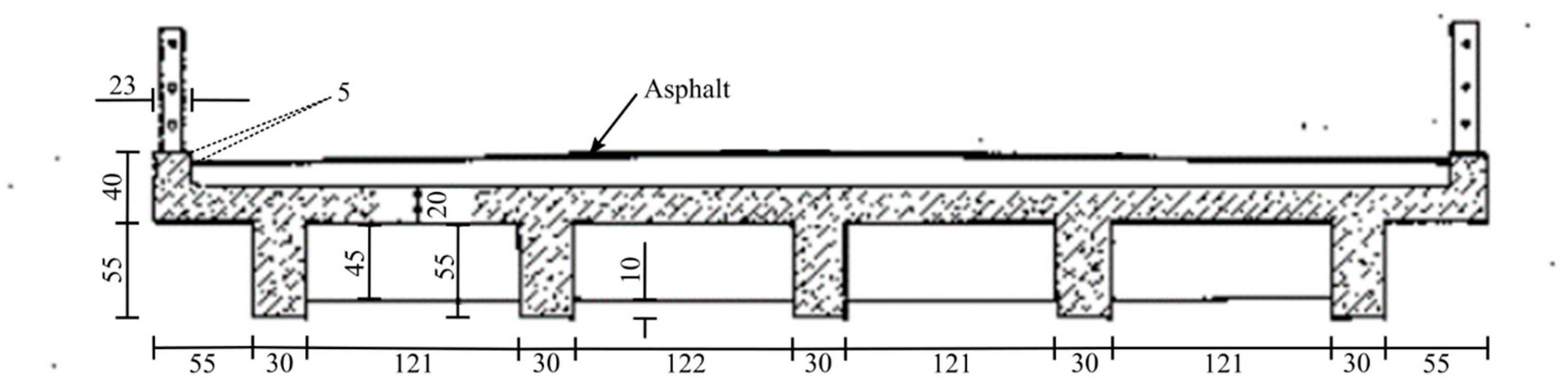
The bridge was constructed as an in situ cast concrete bridge and consisted of one transverse beam and five longitudinal beams that were cast together with the bridge deck plate. The web height of the centrally placed transverse beam was 45 cm, whereas the five longitudinal beams had a height of 55 cm with a horizontal and vertical edge chamfer distance at the ends of approximately 80 cm and 15 cm, respectively. The centrally placed transverse beam height of 45 cm thus leaves 10 cm distance to the bottom face of the longitudinal beams.
The concrete was reported to have a characteristic compression strength of 22.5 MPa. The deformed reinforcement bars had a characteristic yielding strength of 225 MPa and were placed at the beam section bottom in two horizontal rows of five, with a diameter of 20 mm, see Figure 5. Stirrup reinforcement (ø10 mm) with identical yielding strength was placed at a distance of approximately 250 mm throughout the beam length. The bridge classification was Class 20 (20-tonne vehicle) for standard passages and Class 50 (50-tonne vehicle) for conditional passage (type 3), with axle configurations according to the Danish bridge classification system [49,50]. The strengthening aimed to upgrade the bridge capacity to withstand a standard passage Class 50 vehicle and a conditional passage type 3—Class 100 vehicle.
Positioning of the Pre-Stressed Ductile CFRP NSMR System
When designing an anchor block, edge and mutual distances of the adhesively bonded concrete steel anchors are often the dimensioning factor. In addition, adhesively bonded threaded bar concrete anchors have to be mounted in holes drilled between the existing steel reinforcement.
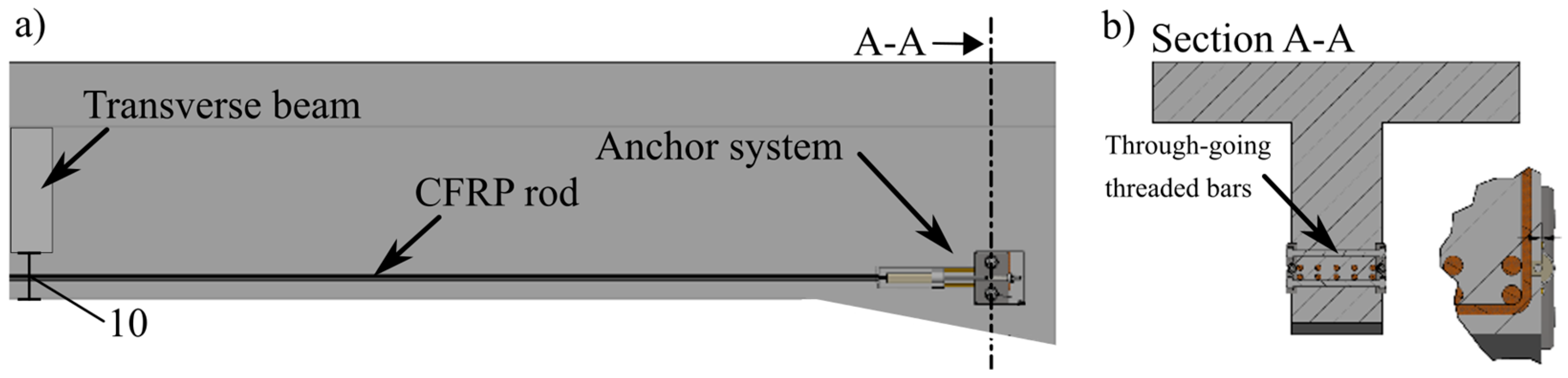
For these reasons, it was impossible to place two strengthening systems on the bottom surface of the longitudinal beams of the case study bridge. However, the chamfered area at the ends of the longitudinal beams provided a potential basis for anchor placing into the concrete web side-cover. A drawing of the CFRP strengthening solution is seen in Figure 5a for this location. The anchor systems were placed on each side of the beams and clamped together by going through adhesively bonded threaded bars, Figure 5b.
In addition, this solution allowed the anchored CFRP ø8 mm rod to be glued into a groove in the concrete web-side cover. The free area underneath the transverse beam of 100 mm enabled the CFRP rod to pass the transverse beam and thus be placed in the entire length of the longitudinal concrete beams.
3. CFRP Strengthening System and Mounting Preparation
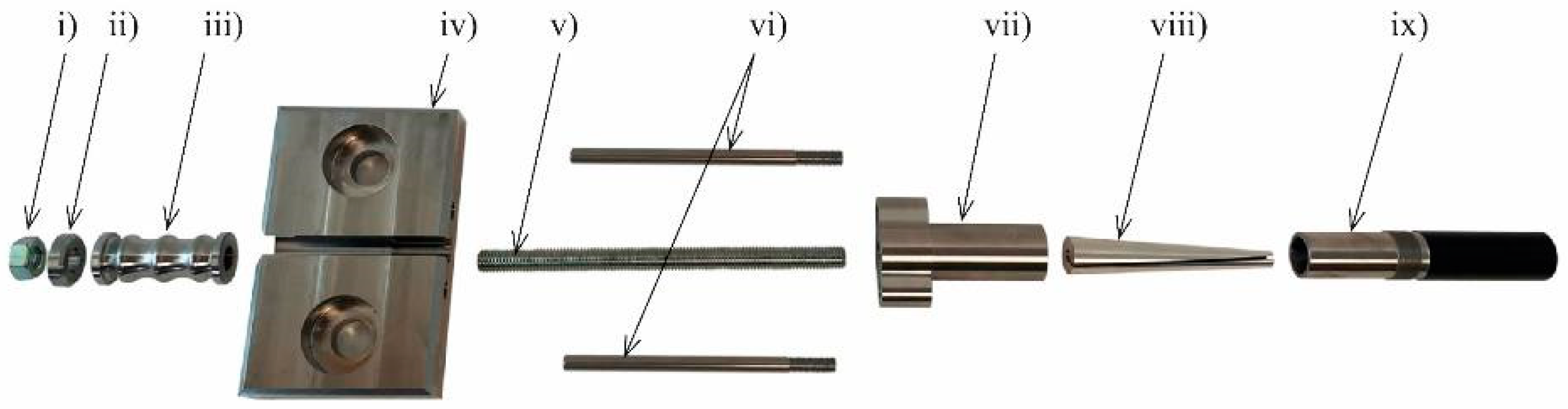
The components of the CFRP anchor system are depicted in Figure 6: (i) nut, (ii) steering washer, (iii) ductile mechanism, (iv) anchor block, (v) threaded bar, (vi) counteracting torque pin, (vii) coupler, (viii) aluminum wedge, (ix) threaded barrel. Table 1 presents the related material properties. The in situ assembling procedure of the CFRP anchors is described in Figure 7.
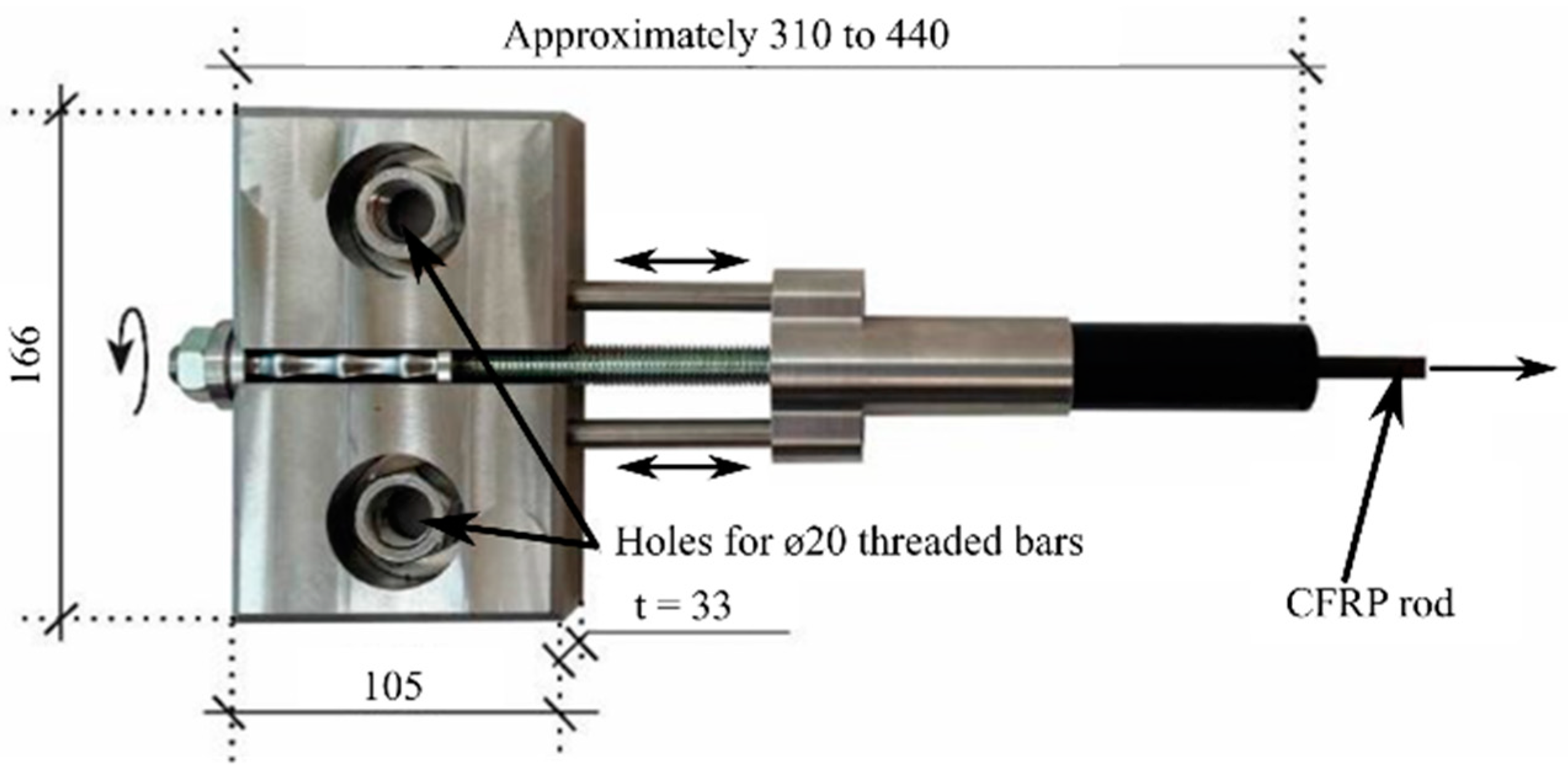
The assembled parts in Figure 7d were mounted through the anchor block (iv), ductile mechanism (iii), and steering washer (ii). Pre-stressing was done by applying torque to the nut (i) mounted on the threaded bar with the steering washer (ii) applied, see Figure 8.
The counteracting torque pins (vi) prevent critical rotation in the barrel (ix), which could potentially cause premature failure of the CFRP rod. The pins are screwed into the coupler “ears” and can slide into the anchor block. Consequently, an undisturbed direct tension of the CFRP rod was deemed possible when pre-stressing was applied through the nut at the back of the anchor system.
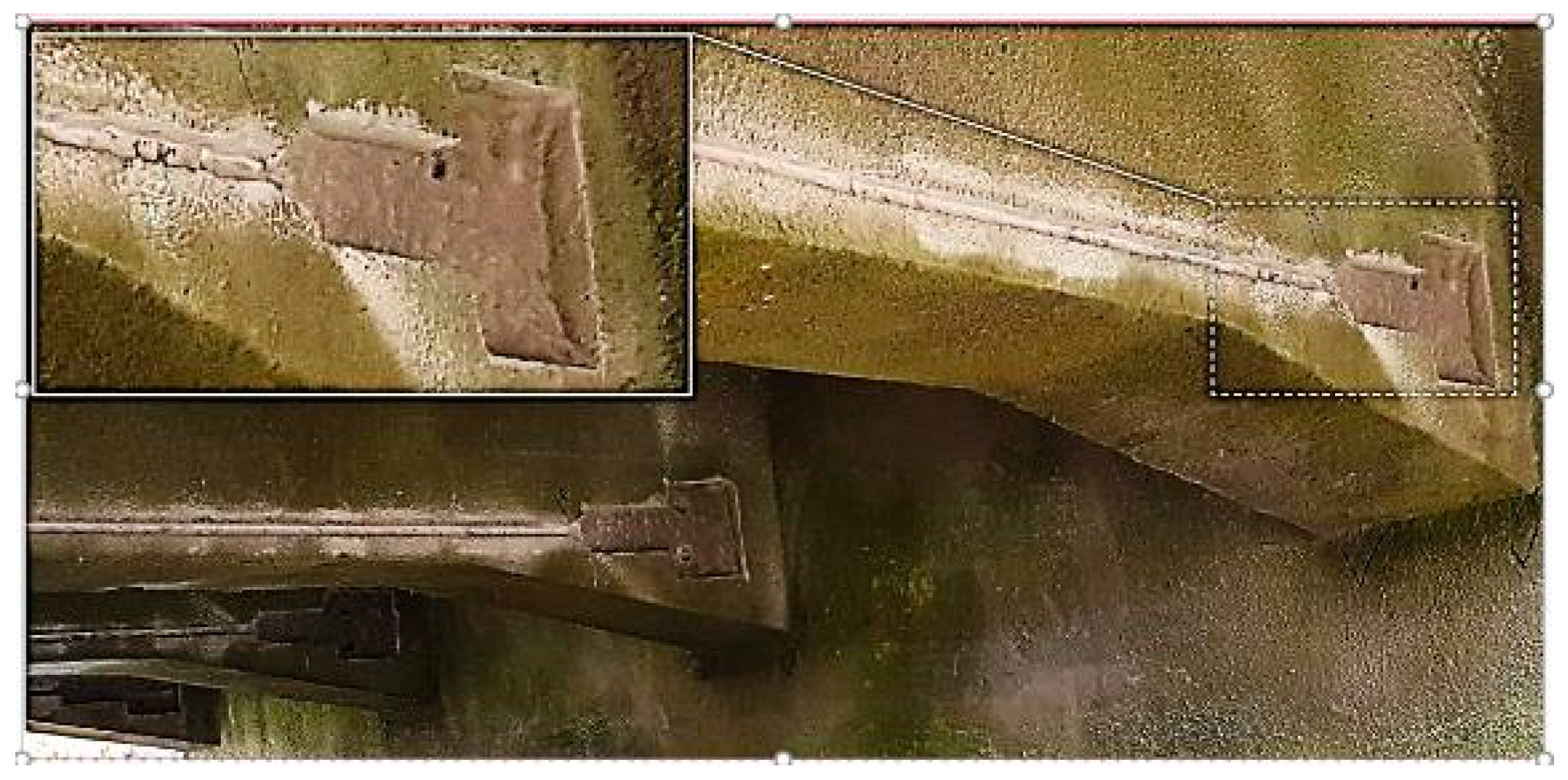
The dimension of the anchor block was designed to fit the structural geometry and reinforcement of the case study bridge. Figure 9 shows the cut-out area and groove in the planned location of Figure 5, in which the anchor block was mounted and the CFRP rod placed, respectively. The depth of the groove ensured that the 8 mm CFRP rod could be covered by the applied flexible adhesive throughout the beam length. The adhesive connected the otherwise free CFRP rod to the structure. The properties of the elastic adhesive are depicted in Table 2.
After the grooves were cut, holes were drilled through the beam web for the 20 mm threaded bars used for the anchor block mounting. The threaded bars were adhesively bonded to the concrete and were used to clamp the anchor block to the beam web at each side of the beam, see Figure 10.
4. Testing of CFRP Anchor System
Before the assembled anchor system could be mounted on the structure, it had to undergo evaluations that ensured the desired response and, at the same time, provided a sufficient safety level. It was hypothesized that the designed yielding threshold provided a consistent failure mode initiation which ensures that unique ultimate failure mode resistances above this threshold can be disregarded, with sufficient reliability. This was deemed a sound approach if combined with in situ proof-loading of the system. Proof-loading of the system eliminates doubts concerning undesirable failure modes that may occur below the proof-load level.
4.1. Positioning of the Pre-Stressed Ductile CFRP NSMR System
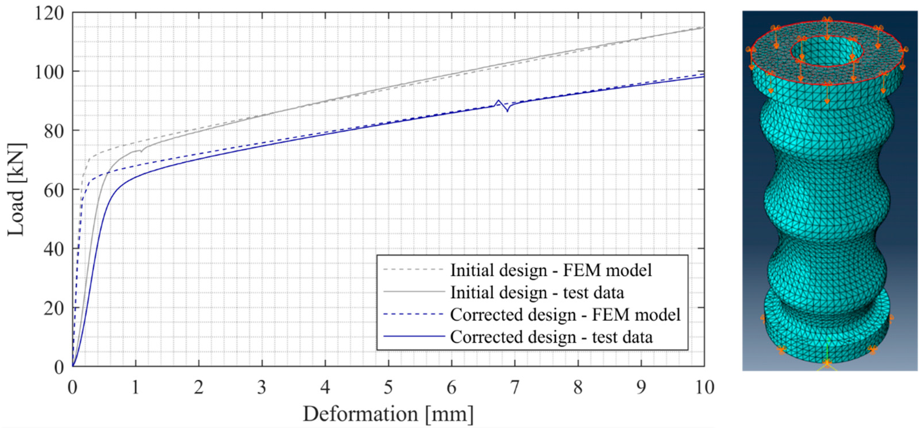
The ductile mechanism is what defines the yielding threshold of the system, and thus, this had to be designed to provide a consistent yield strength. The yielding threshold would then function as the system design yield resistance. The desired yielding threshold, assigned in the project, for each anchor was 50 kN (as ULS design resistance). The initial design and verification of the ductile mechanism response were thus performed to comply with this demand. The initial test results are shown in Figure 11, along with the finite element (FE) simulation. It is seen that there is a slight discrepancy between the stiffness in the linear elastic regime, which is due to the test setup and machine stiffness. The commercial program ABAQUS [51] was used for the finite element evaluation, where 3D stress, quadratic (geometric order), and tetrahedron mesh were used to simulate the first part of the ductile mechanism response curve and, thus, the yielding threshold magnitude. A young’s modulus of 200 GPa and Poisson’s ratio of 0.3 was used as input to the analysis. Linear regression was used for the yielding regime, where yield stresses of 400 MPa and 2000 MPa were used in conjunction with plastic strains of 0 and 1, respectively. Similar yielding thresholds were obtained when comparing the two tested ductile mechanisms with theoretical simulations in Figure 11. Approximately 70 kN was obtained in the first evaluation, but due to the inclined yielding regime, this was subsequently reduced to approximately 60 kN to enable extended ductile behavior until ultimate system failure occurred.
4.2. Anchor System Testing
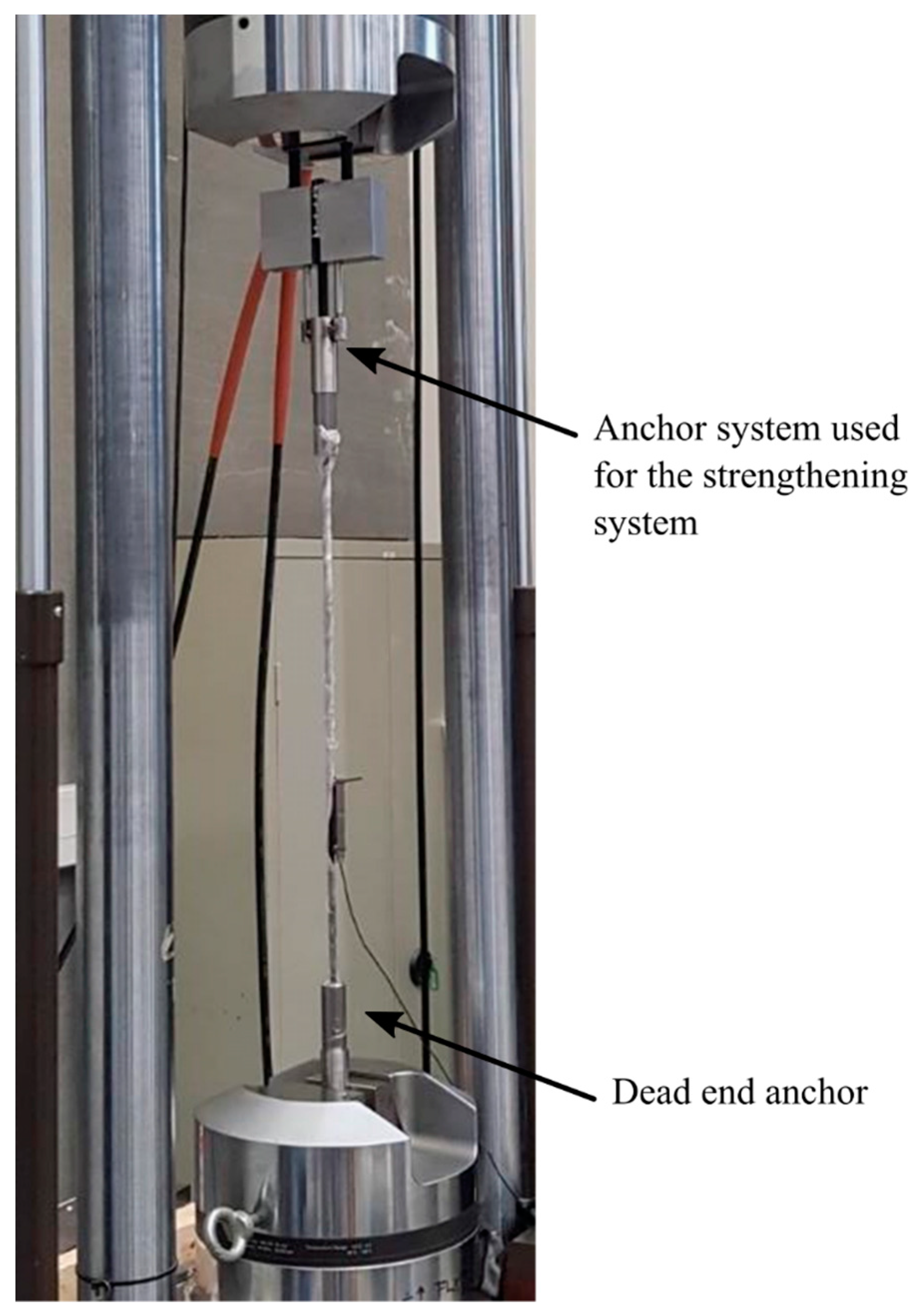
Figure 12 shows the anchor system test specimen used for the pre-stressed strengthening approach, mounted in the MTS 810 material test machine. A 1 m ø8 CFRP rod test specimen was anchored by the system in the top jaw and a dead-end anchor in the bottom jaw. A deformation-controlled load rate of 2 mm/min was used for the test procedure.
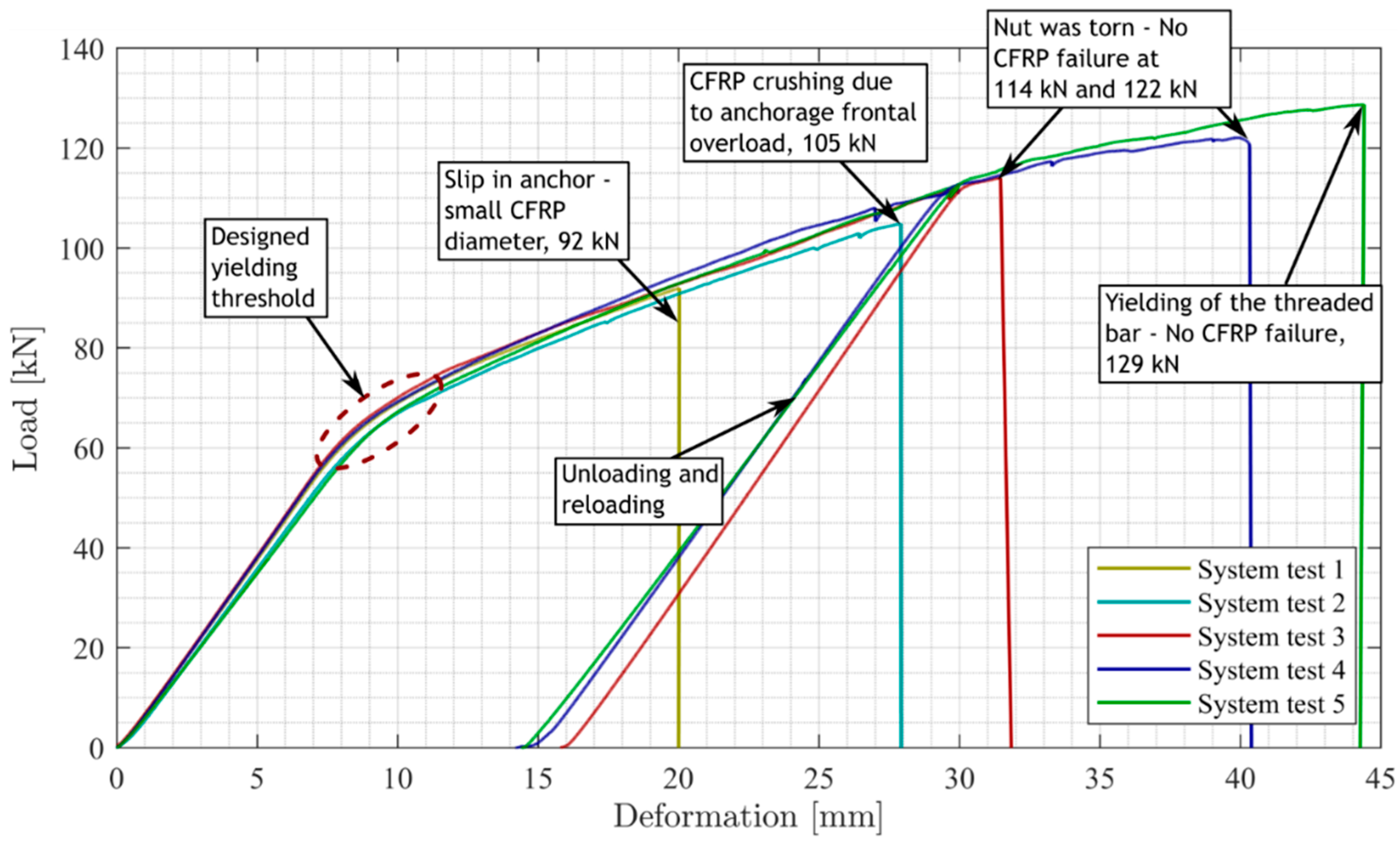
Five system tests were performed on the anchor system. The response curves of these tests are seen in Figure 13, including a breakdown of the respective failure modes. It is seen that all ultimate failure mods, except the designed yielding threshold, are brittle. System tests 1 and 2 were CFRP anchor-related failure modes. It should be noted that the slip failure of system test 1 at 92 kN was due to the use of the lowest diameter of the produced CFRP rod batches (approximately 7.85 mm), which was deemed to provide a lower bound ultimate CFRP anchor capacity value. The failure of system test 2 at 105 kN was a frontal overload crushing of the CFRP rod. The remaining failures occurred at higher capacities in the nut and threaded components of the anchor system, which were designed with minimal dimensions for optimal design. The three tests that reached 30 mm deformation were unloaded and afterwards reloaded until failure occurred. The curves from loading and reloading are combined at the load termination point in the first cycle and yield initiation point of the second cycle (system tests 3, 4, and 5).
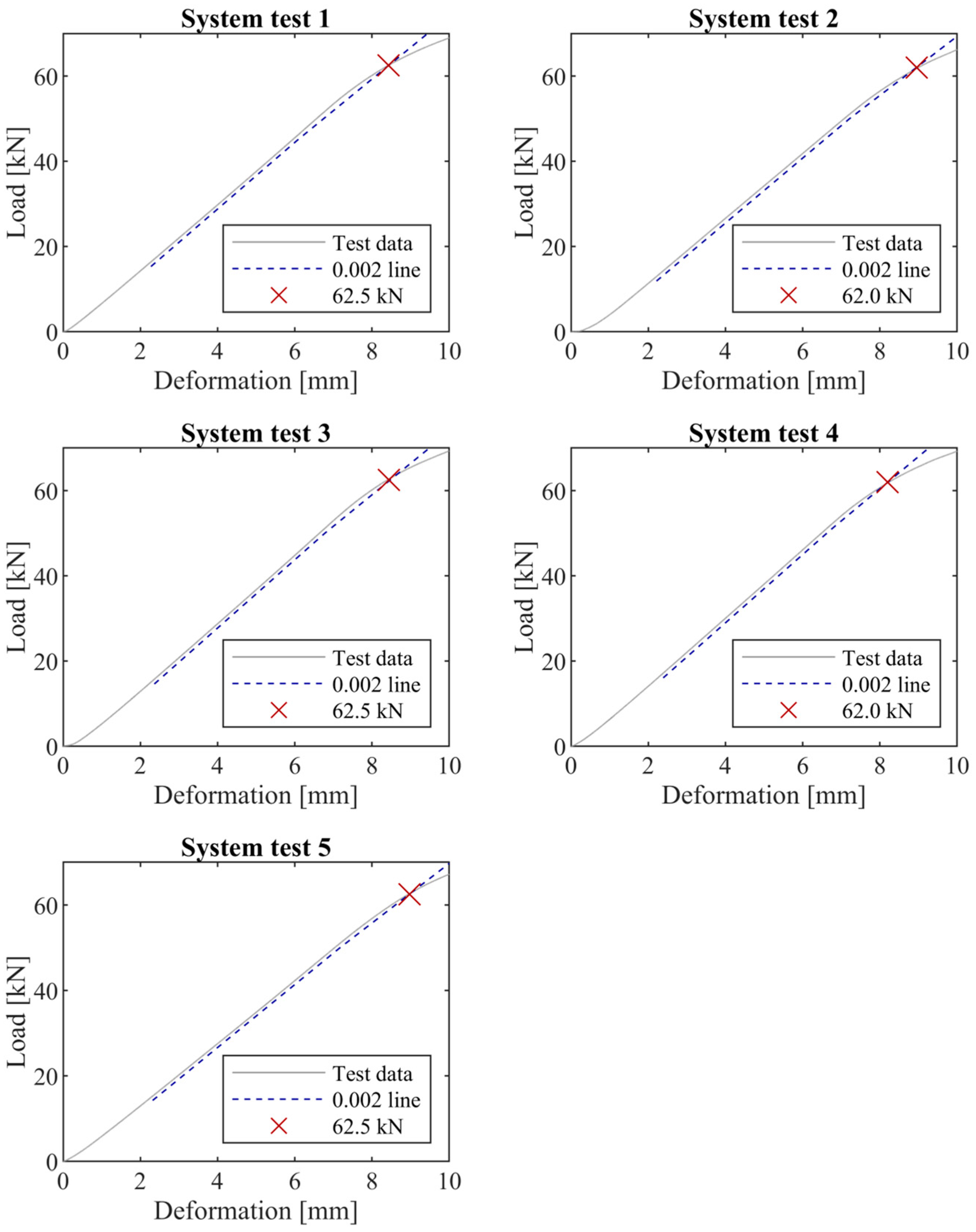
The tests provide an example of several deviating ultimate failure modes, which also may occur in any strengthening system or joint, including brittle and ductile behavior. The response curves are, however, almost identical until each of the respective ultimate failures occurs. As such, the response curves include a linear regime, a yielding threshold, and an inclined yielding regime that terminates when the failure load of a component is reached. Thus, the ductile mechanism seems to control the behavior well, with minor deviations between the curves and a pronounced yielding regime in all tests. In addition, the controlled system behavior of the tests correlates well when translating the linear regime of each test to the design “yielding” threshold using a yield strain of 0.002, which corresponds to a translation of 0.14 mm. The test curves and yielding translation line are depicted in Figure 14, where the intersection between the lines provides the yielding thresholds. The yield thresholds show only minor variation, and the results serve as input for determining the design yield threshold.
4.3. Design Yield Resistance
To the authors’ best knowledge, a novel approach (apart from presenting the novel system) is to perform a system-related evaluation of the characteristic and design strength values, which is an extension of the component-based provisions in EN1990:2002 Annex D [46]. Such a system-based approach is used for other materials and structural components within the application area for the Eurocodes, but not for anchor systems as considered in this paper. The evaluation of the values is based on the Design Value Format method with parameters in EN1990:2002 Annex D, see Tables 2 and 4 in [46]. In the following analysis, characteristic values are defined as 5% quantiles, and design values were obtained using the Design Value Format method with a target 50-year reliability index equal to 3.8 and a sensitivity factor equal to 0.8. Subsequently, the characteristic and design value are determined assuming no prior knowledge (unknown coefficient of variation), including statistical uncertainty due to a limited number of tests. The characteristic resistance value is obtained by assuming a lognormal distribution of the resistance:
where:
- is the expected value of log of test results;
- is the standard deviation of log of test results;
- n is the number of data;
- are the data from tests;
- is a factor used to obtain the characteristic value with being the p = 0.05 quantile of the Student-t distribution with n − 1 degrees of freedom.
The design value is obtained from:
where:
- is a factor based on the recommended lifetime reliability index = 3.8 and a sensitivity factor 0.8 implying an exceedance probability = 0.0012, with being the standard Normal distribution function.
The partial material factor is calculated from:
Probabilistic results based on the five tests are seen in Table 3.
Following the Eurocode recommendations, the design value in the table provides confidence in the system response and may ensure sufficient safety. However, it can be probabilistically argued that the ultimate failure modes (Figure 13), which occur above the yielding threshold, could provide a lower realization of the resistance. This could theoretically be realized through a potential large scatter (standard deviation) of one or multiple failure modes. Still, it is seen from the tests that the obtained ultimate capacities for each of these failure modes seem significantly larger than the determined ULS design yield resistance of 60.3 kN. As such, even with a significant standard deviation of these failure modes, the probability of obtaining a lower resistance value is small. This small probability of getting a lower resistance is, however, one of the most challenging aspects when introducing novel systems with many potential failure modes. The issue thus deserves significant attention, not only for novel systems but also for existing construction parts and joints, where similar realizations may be obtained. For the presented case, it still needs to be verified probabilistically that there is a low or no probability that an ultimate capacity value will be lower than the lower boundary provided through the designed and tested yield resistance threshold. This cannot be verified through the current methods. A detailed probabilistic modeling and safety verification of this hypothesis will be investigated further in a follow-up paper. A more direct approach was applied in the presented research pilot project to verify further that no systems with lower resistance arise when applying these. This approach relates to the installation procedure, which includes proof loading of each system used in this project, thus verifying the resistance. It should, however, be noted that this procedure was for detailed investigations of the novel system and is thus unique to the particular project.
5. Mounting, Prestressing, and Verification
Following the experimental testing of the anchor system, the system could be mounted on the case-study bridge, as shown in Figure 10, where the pre-stressing procedure was performed in two phases. The described proof loading, Phase 1, consisted of a step-wise pre-stressing to the desired proof-loading magnitude. Phase 2 related to the time-dependent effects, where the system was unloaded after three weeks and pre-stressed again to evaluate and account for potential pre-stress losses.
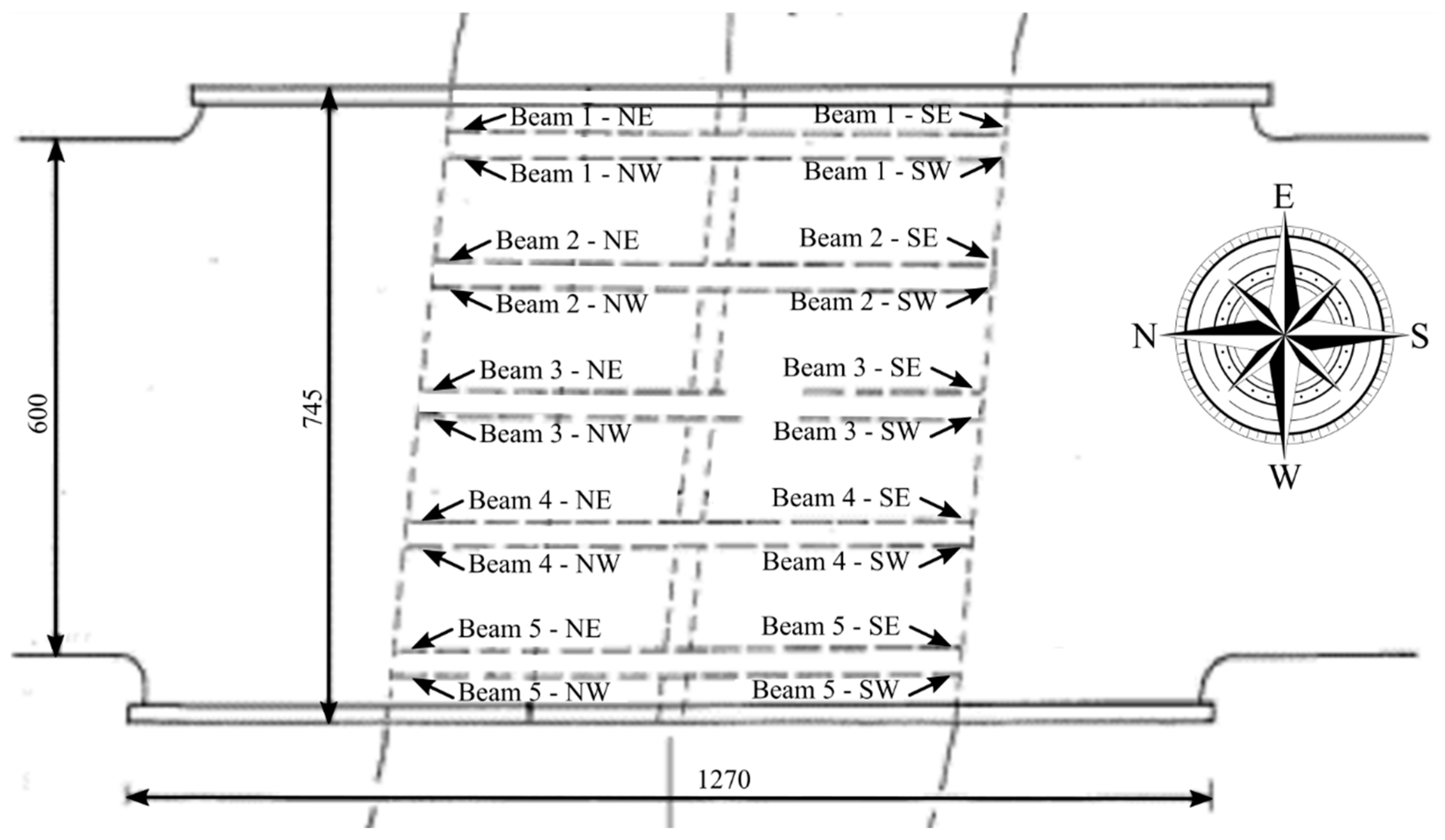
5.1. Pre-Stressing, Phase 1
Figure 15 shows the numbering of the beams on which the anchors were step-wise pre-stressed to 10 kN, 25 kN, and 55 kN in the beam sequence; 3, 2, 4, 1, and 5. The pre-stressing level (proof loading level) of 55 kN was chosen in relation to the required design value of 50 kN and the ULS design resistance estimated to 60.3 kN. As such, the proof-loading eliminates any possible failures lower than 55 kN, and thus significantly reduces the risk of an undesired brittle failure without warning. It should be noted that the reliability assessment of the proof load level depends on the level of knowledge on the resistance, and since the resistance of the strengthening system can be modeled with relatively small uncertainty, the selected proof load level was considered sufficient. Pre-stressing at each step was finalized for all anchors before the next phase was initiated.
Table 4 depicts the actual pre-stressing magnitudes of the proof-loadings, με/(kN), measured by a strain gauge of type HBM 6/350VE LY41 mounted on each CFRP rod. An ø8 mm CFRP rod and an elastic modulus of 160 GPa were used as background for the reference values in each loading step of 1250 με (10 kN), 3150 με (25 kN), and 6875 με (55 kN). After three hours, the tensile levels were measured again to evaluate the system seating, ε3 (kN3). It was seen that the strain values were acceptable after three hours, where only an insignificant reduction was seen. Accordingly, the achieved pre-stressing values fulfilled the request of 50 kN ULS design resistance. No additional post-tensioning was thus needed to adjust tensioning magnitudes. After the values were approved, the strain gauge wires were disconnected and later reconnected for phase 2, which was initiated after three weeks.
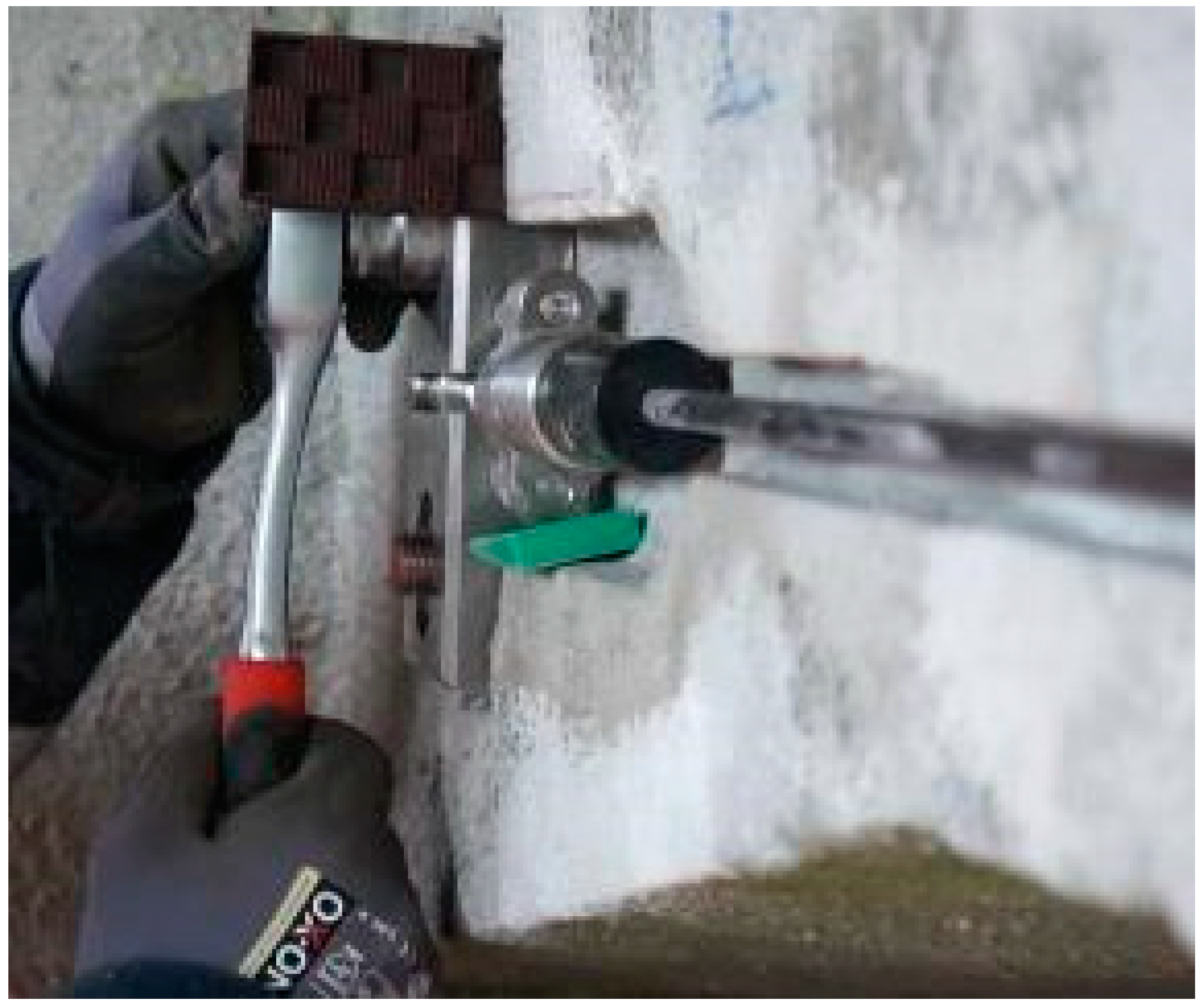
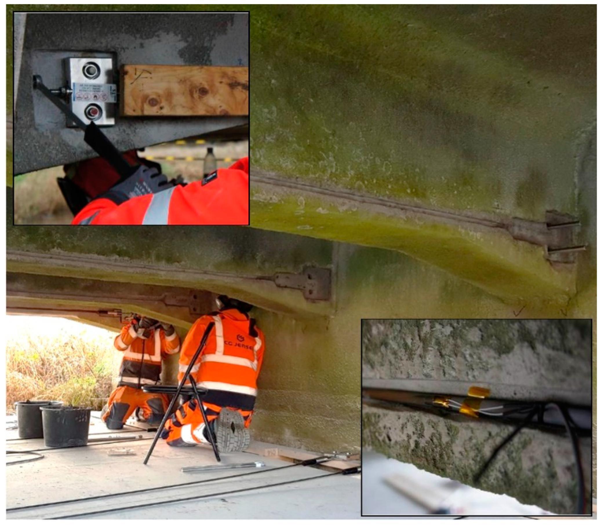
Figure 16 depicts the site installation of the strengthening system where pre-stressing was performed with a single-head wrench, applying torque to the system nut.
The pre-stressing procedure worked as intended up to the desired pre-stressing levels at which no damage was identified for the full strengthening systems and associated anchor locations. Proof-loading by pre-stressing to 55 kN furthermore demonstrated the desired resistance for all 20 unique anchor systems and ensured that no failure modes were initiated at lower load levels. The CFRP rod of the strengthening system was left unbonded until the initiation of phase 2.
5.2. Pre-Stressing, Phase 2
The second phase was initiated after three weeks, where acquisition was performed after re-connecting the strain gauge wires. In this phase, the system was unloaded and pre-stressed again to 55 kN using identical loading steps as for phase 1. The unloading was done to account for possible relaxation effects of the unbonded strengthening system.
Table 5 depicts the initial three-hour strain value of phase 1 (με3) compared to the measured value after three weeks (μεw). It is seen that the pre-stressing magnitudes are reduced by values ranging from approximately 0.2 to 1.6 kN, corresponding to a full system deformation of 0.2–1.3 mm, respectively (using a strengthening system length of 6500 mm).
The values depicted in Table 4. describe the full system behavior. Separating these values between the anchor systems, a deformation ranging from 0.1–0.8 mm was thus obtained. Table 6 shows the final pre-stressing magnitudes approximately at the desired 55 kN (1094 MPa).
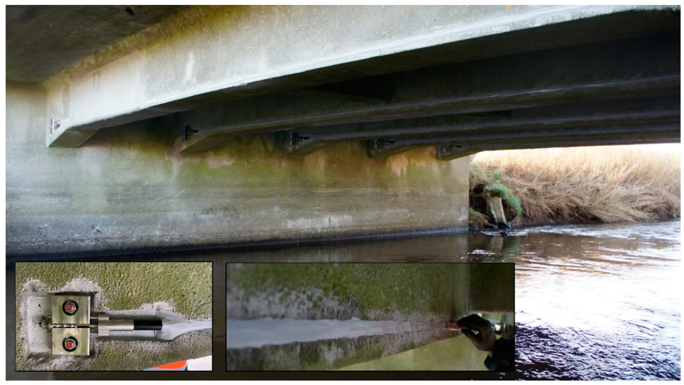
After verifying the desired pre-stressing magnitudes, adhesive bonding of the CFRP rod was done by using the flexible adhesive in pre-cut grooves. Figure 17 shows the final result of the applied strengthening with the adhesive applied into the groove, thus bonding it to the structure along the beam length and how it terminates at the anchor system location.
6. Conclusions
The paper presents research that demonstrates the response of a novel response-controlled pre-stressing anchor system used for CFRP NSMR strengthening. An initial assessment of an in situ pre-cast concrete bridge was performed to provide a basis for the most desirable anchor system placement. Five anchor systems were tested in the laboratory to verify the anchor system’s controlled response and consistency with a special focus on the designed yielding threshold and yielding regime. The ultimate capacities occurred at significantly higher magnitudes than the yielding threshold for all tests. A concern was, however, that a large standard deviation of a unique ultimate failure mode could lead to a realization of a lower resistance value than the yielding threshold. The probabilistic anchor system assessment based on laboratory tests in combination with in situ proof loading was deemed a sound approach to disregard the probability of obtaining the hypothesized lower value realization. Based on the research hypotheses and questions, the following conclusions can be drawn:
- The laboratory test showed excellent consistency when comparing the load/deformation curves of the anchor system.
- The response can be tailored, primarily controlled by the ductile mechanism.
- Controlled yielding was obtained for all anchor systems tested in the laboratory, thus ensuring a low-yielding threshold safety factor (γR = 1.02).
- The ULS design (yielding threshold) resistance of 60.3 kN fulfilled the required demand for the ULS design resistance of 50 kN, required from the presented unique pilot project.
- In situ proof loading of the strengthening systems (20 anchor systems) showed no signs of distress.
- Proof loading ensured that variations in the unique ultimate failure modes of the mounted anchor systems did not compromise the desired resistance (yielding threshold).
- A good basis is provided for upcoming systems, which can resist significantly higher tailored load magnitudes combined with a desired response.
- A more detailed probabilistic verification seems necessary to ensure that the yielding threshold provides a minimum capacity level not compromised by ultimate capacity variations and to avoid proof-loading entirely.
- The developed NSMR CFRP pre-stressed strengthening system worked as desired and ensured fast mounting and effective controlled prestressing
- After three weeks, acceptable prestress losses ranging from approximately 0.2 to 1.6 kN were observed, corresponding to a full strengthening system (including anchors) and a deformation of 0.2–1.3 mm, respectively.
- The applied strengthening resulted in a bridge class upgrading from standard passage class 20 to class 50 and conditional passage (type 3) class 50 to class 100, as required.
It is thus seen that the ductile response controlled strengthening system works as desired, but a probabilistic assessment may provide uncertainty in relation to the reliability and probability of failure. It is still an open question as to whether laboratory testing for such systems verifies all possible failure modes and whether these are representative if forced to occur. From an economical perspective, such evaluations can cause a significant burden to a research project. In situ proof loading can ensure validation of a system, but such a procedure would often be considered an undesirable and cumbersome process. In addition, proof loading does not verify that the yielding regime will be activated. The designed ductile unit response may solve this challenge since it can be constructed to meet a desired capacity demand and response.
Author Contributions
Conceptualization, J.W.S.; methodology, J.W.S. and J.D.S.; software, J.W.S., J.D.S. and C.O.C.; validation, J.W.S. and J.D.S.; formal analysis, J.W.S. and J.D.S.; investigation, J.W.S.; resources, J.W.S.; data curation, J.W.S. and J.D.S.; writing—original draft preparation, J.W.S.; writing—review and editing, J.W.S., J.D.S. and C.O.C.; visualization, J.W.S. and C.O.C.; supervision, J.W.S. and J.D.S.; project administration, J.W.S.; funding acquisition, J.W.S. All authors have read and agreed to the published version of the manuscript.
Funding
The funding source do not wish to be revealed as stated in this section.
Data Availability Statement
All data and information needed for the evaluations discussed are provided in the paper.
Acknowledgments
A sincere gratitude is addressed to S&P Clever Reinforcement Company AG and Business Manager Morten Frost Kamphøvener from S&P Reinforcement Nordic for supporting the presented pilot project and ongoing research at Aalborg University (AAU). Thank you very much to Vejen municipality and COWI A/S, for giving us the opportunity to initiate and carry out the pilot project. Additionally, a great appreciation is dedicated to craftsmen from CG Jensen and technical staff from AAU, for their professionalism and excellent work.
Conflicts of Interest
The authors declare no conflict of interest.
References
- El-Hacha, R.; Rizkalla, S.H. Near-Surface-Mounted Fiber-Reinforced Polymer Reinforcements for Flexural Strengthening of Concrete Structures. ACI Struct. J. 2004, 101, 717–726. [Google Scholar]
- Mohamed Ali, M.S.; Oehlers, D.J.; Griffith, M.C.; Seracino, R. Interfacial Stress Transfer of near Surface-Mounted FRP-to-Concrete Joints. Eng. Struct. 2008, 30, 1861–1868. [Google Scholar] [CrossRef]
- Rashid, R.; Oehlers, D.J.; Seracino, R. IC Debonding of FRP NSM and EB Retrofitted Concrete: Plate and Cover Interaction Tests. J. Compos. Constr. 2008, 12, 160–167. [Google Scholar] [CrossRef]
- Seracino, R.; Jones, N.M.; Ali, M.S.; Page, M.W.; Oehlers, D.J. Bond Strength of Near-Surface Mounted FRP Strip-to-Concrete Joints. J. Compos. Constr. 2007, 11, 401–409. [Google Scholar] [CrossRef]
- Sena-Cruz, J.M.; Barros, J.A.O.; Coelho, M.R.F.; Silva, L.F.F.T. Efficiency of Different Techniques in Flexural Strengthening of RC Beams under Monotonic and Fatigue Loading. Constr. Build. Mater. 2012, 29, 175–182. [Google Scholar] [CrossRef] [Green Version]
- Al-Mahmoud, F.; Castel, A.; Franois, R. Failure Modes and Failure Mechanisms of RC Members Strengthened by NSM CFRP Composites—Analysis of Pull-out Failure Mode. Compos. Part B Eng. 2012, 43, 1893–1901. [Google Scholar] [CrossRef]
- Schmidt, J.W.; Krabbe, J.; Sørensen, N.O.; Hertz, K.D.; Goltermann, P.; Sas, G. CFRP Strengthening of RC Beams Using a Ductile Anchorage System. In Proceedings of the 8th International Conference on Fibre-Reinforced Polymer (FRP) Composites in Civil Engineering, CICE 2016, Hong Kong, China, 14–16 December 2016. [Google Scholar]
- Schmidt, J.W.; Hertz, K.D.; Goltermann, P. NSMR Strengthening of Short RC Beams Using Activated Anchorage. In Proceedings of the 9th International Conference on Fibre-Reinforced Polymer (FRP) Composites in Civil Engineering, CICE 2018, Paris, France, 17–19 July 2018. [Google Scholar]
- Sabau, C.; Popescu, C.; Sas, G.; Schmidt, J.W.; Blanksvärd, T.; Täljsten, B. Strengthening of RC Beams Using Bottom and Side NSM Reinforcement. Compos. Part B Eng. 2018, 149, 82–91. [Google Scholar] [CrossRef] [Green Version]
- Nordin, H.; Täljsten, B. Concrete Beams Strengthened with Prestressed Near Surface Mounted CFRP. J. Compos. Constr. 2006, 10, 60–68. [Google Scholar] [CrossRef]
- American Concrete Institute. ACI 440.2R-17: Guide for the Design and Construction of Externally Bonded FRP Systems for Strengthening Concrete Structures; American Concrete Institute: Indianapolis, IN, USA, 2017; ISBN 9781945487590. [Google Scholar]
- Täljsten, B. Strengthening of Beams by Plate Bonding. J. Mater. Civ. Eng. 1997, 9, 206–212. [Google Scholar] [CrossRef]
- Triantafillou, T.C.; Antonopoulos, C.P. Design of Concrete Flexural Members Strengthened in Shear with FRP. J. Compos. Constr. 2000, 4, 198–205. [Google Scholar] [CrossRef]
- Smith, S.T.; Gravina, R.J. Modeling Debonding Failure in FRP Flexurally Strengthened RC Members Using a Local Deformation Model. J. Compos. Constr. 2007, 11, 184–191. [Google Scholar] [CrossRef]
- Teng, J.G.; Smith, S.T.; Yao, J.; Chen, J.F. Intermediate Crack-Induced Debonding in RC Beams and Slabs. Constr. Build. Mater. 2003, 17, 447–462. [Google Scholar] [CrossRef]
- Said, H.; Wu, Z. Evaluating and Proposing Models of Predicting IC Debonding Failure. J. Compos. Constr. 2008, 12, 284–299. [Google Scholar] [CrossRef]
- Tworzewski, P.; Alexy, J.K.; Barnes, R.W. Intermediate Crack Debonding of Externally Bonded FRP Reinforcement—Comparison of Methods. Materials 2022, 15, 7390. [Google Scholar]
- Gao, B.; Leung, C.K.Y.; Kim, J.K. Prediction of Concrete Cover Separation Failure for RC Beams Strengthened with CFRP Strips. Eng. Struct. 2005, 27, 177–189. [Google Scholar] [CrossRef]
- Corden, G.; Ibell, T.; Darby, A. Concrete Cover Separation Failure in Near-Surface Mounted CFRP Strengthened Concrete Structures. Struct. Eng. 2008, 86, 19–21. [Google Scholar]
- Wight, R.G.; Green, M.F.; Erki, M.-A. Prestressed FRP Sheets for Poststrengthening Reinforced Concrete Beams. J. Compos. Constr. 2001, 5, 214–220. [Google Scholar] [CrossRef]
- Diab, H.; Wu, Z.; Iwashita, K. Short and Long-Term Bond Performance of Prestressed FRP Sheet Anchorages. Eng. Struct. 2009, 31, 1241–1249. [Google Scholar] [CrossRef]
- Yang, D.S.; Park, S.K.; Neale, K.W. Flexural Behaviour of Reinforced Concrete Beams Strengthened with Prestressed Carbon Composites. Compos. Struct. 2009, 88, 497–508. [Google Scholar] [CrossRef]
- Chen, C.; Chen, J.; Zhou, Y.; Sui, L.; Hu, B. Design of Ductile H-Anchorage for Strengthening Reinforced Concrete Beams with Prestressed FRP. Constr. Build. Mater. 2021, 307, 124883. [Google Scholar] [CrossRef]
- D’Amato, M.; Laterza, M.; Casamassima, V.M. Seismic Performance Evaluation of a Multi-Span Existing Masonry Arch Bridge. Open Civ. Eng. J. 2018, 11, 1191–1207. [Google Scholar] [CrossRef]
- Modena, C.; Tecchio, G.; Pellegrino, C.; da Porto, F.; Donà, M.; Zampieri, P.; Zanini, M.A. Reinforced Concrete and Masonry Arch Bridges in Seismic Areas: Typical Deficiencies and Retrofitting Strategies. Struct. Infrastruct. Eng. 2015, 11, 415–442. [Google Scholar] [CrossRef]
- American Concrete Institute. ACI 440.4R-04: Guide for Prestressing Concrete Structures with FRP Tendons; American Concrete Institute: Farmington Hills, MA, USA, 2004. [Google Scholar]
- Nanni, A. North American Design Guidelines for Concrete Reinforcement and Strengthening Using FRP: Principles, Applications and Unresolved Issues. Constr. Build. Mater. 2003, 17, 439–446. [Google Scholar] [CrossRef]
- Jiang, Z.; Fang, Z.; Fang, C.; Li, Q.; Wang, Z. Experimental Investigation on High-Temperature Creep Behavior of Carbon Fiber Reinforced Polymer Cable. Compos. Struct. 2022, 291, 115533. [Google Scholar] [CrossRef]
- Schmidt, J.W.; Bennitz, A.; Täljsten, B.; Goltermann, P.; Pedersen, H. Mechanical Anchorage of FRP Tendons—A Literature Review. Constr. Build. Mater. 2012, 32, 110–121. [Google Scholar] [CrossRef]
- Bennitz, A.; Grip, N.; Schmidt, J.W. Thick-Walled Cylinder Theory Applied on a Conical Wedge Anchorage. Meccanica 2011, 46, 959–977. [Google Scholar] [CrossRef] [Green Version]
- Hansen, C.S.; Schmidt, J.W.; Stang, H. Transversely Compressed Bonded Joints. Compos. Part B Eng. 2012, 43, 691–701. [Google Scholar] [CrossRef]
- Schmidt, J.W.; Bennitz, A.; Täljsten, B.; Pedersen, H. Development of Mechanical Anchor for CFRP Tendons Using Integrated Sleeve. J. Compos. Constr. 2010, 14, 397–405. [Google Scholar] [CrossRef]
- Grelle, S.V.; Sneed, L.H. Review of Anchorage Systems for Externally Bonded FRP Laminates. Int. J. Concr. Struct. Mater. 2013, 7, 17–33. [Google Scholar] [CrossRef] [Green Version]
- Cuntze, R.G.; Freund, A. The Predictive Capability of Failure Mode Concept-Based Strength Criteria for Multidirectional Laminates. Compos. Sci. Technol. 2004, 64, 343–377. [Google Scholar] [CrossRef]
- Schmidt, J.W. External Strengthening of Building Structures with Prestressed CFRP; Technical University of Denmark: Lyngby, Denmark, 2011. [Google Scholar]
- Bennitz, A.; Schmidt, J.W.; Täljsten, B. Failure Modes of Prestressed CFRP Rods in a Wedge Anchored Set-Up. In Proceedings of the Advanced Composites in Construction 2009, ACIC 2009—Proceedings of the 4th International Conference, Toronto, ON, Canada, 16–17 July 2009. [Google Scholar]
- Piątek, B.; Siwowski, T. Experimental Study on Flexural Behaviour of Reinforced Concrete Beams Strengthened with Passive and Active CFRP Strips Using a Novel Anchorage System. Arch. Civ. Mech. Eng. 2022, 22, 1–17. [Google Scholar] [CrossRef]
- Heydarinouri, H.; Motavalli, M.; Nussbaumer, A.; Ghafoori, E. Development of a Mechanical Wedge–Barrel Anchor for CFRP Rods: Static and Fatigue Behaviors. J. Compos. Constr. 2021, 25, 04021015. [Google Scholar] [CrossRef]
- Heydarinouri, H.; Vidovic, A.; Nussbaumer, A.; Ghafoori, E. FE Analysis and Experimental Validation of Mechanical Wedge–Barrel Anchors for CFRP Rods. Compos. Struct. 2021, 275, 114509. [Google Scholar] [CrossRef]
- Schmidt, J.W.; Smith, S.T.; Täljsten, B.; Bennitz, A.; Goltermann, P.; Pedersen, H. Numerical Simulation and Experimental Validation of an Integrated Sleeve-Wedge Anchorage for CFRP Rods. J. Compos. Constr. 2011, 15, 284–292. [Google Scholar] [CrossRef]
- Schmidt, J.W.; Christensen, C.O.; Goltermann, P.; Hertz, K.D. Shared CFRP Activation Anchoring Method Applied to NSMR Strengthening of RC Beams. Compos. Struct. 2019, 230, 111487. [Google Scholar] [CrossRef]
- Schmidt, J.W.; Sena-Cruz, J.; Goltermann, P.; Christensen, C.O. Experimental and Numerical Studies on the Shared Activation Anchoring of NSMR CFRP Applied to RC Beams. In Proceedings of the APFIS 2019 Proceedings—7th Asia-Pacific Conference on FRP in Structures, Gold Coast, Australia, 10–13 December 2019. [Google Scholar]
- Schmidt, J.W.; Christensen, C.O.; Goltermann, P. Ductile Response Controlled EW CFRP Anchor System. Compos. Part B Eng. 2020, 201, 108371. [Google Scholar] [CrossRef]
- Schmidt, J.W.; Christensen, C.O.; Goltermann, P.; Sena-Cruz, J. Activated Ductile CFRP NSMR Strengthening. Materials 2021, 14, 2821. [Google Scholar] [CrossRef]
- Schmidt, J.W.; Christensen, C.O.; Goltermann, P.; Sena-Cruz, J. Activated CFRP NSMR Ductile Strengthening System. In RILEM Bookseries; Springer: Berlin/Heidelberg, Germany, 2022; Volume 34, pp. 349–361. [Google Scholar]
- EN 1990; Eurocode: Basis of Structural Design. European Committee for Standardization: Bruxelles, Belgium, 2002.
- ISO 2394; General Principles on Reliability for Structures: International Standard ISO; Bind 2394. International Organization for Standardization: Geneva, Zwitserland, 2015.
- Joint Committee on Structural Safety. Probabilistic Model Code; Joint Committee on Structural Safety: Deift, The Netherlands, 2002. [Google Scholar]
- Vejdirektoratet (The Danish Road Directorate). Vejledning Til Belastnings- Og Beregningsgrundlag; Vejdirektoratet (The Danish Road Directorate): Hedehusene, Denmark, 2010. [Google Scholar]
- Vejdirektoratet (The Danish Road Directorate). DS/EN 1991-2 DK NA:2017, Annex A: Lastmodeller for Klassificering Og Bæreevnevurdering (Models of Special Vehicles for Road Bridges); Vejdirektoratet (The Danish Road Directorate): Hedehusene, Denmark, 2017. [Google Scholar]
- ABAQUS, Version Abaqus/CAE; Dassault Systèmes Simulia Corp: Johnston, RI, USA, 2021.
Figure 1.
Increased ductility in the combined system response [43].
Figure 1.
Increased ductility in the combined system response [43].

Figure 2.
Strengthening effect of using the ductile CFRP strengthening system [44].
Figure 2.
Strengthening effect of using the ductile CFRP strengthening system [44].

Figure 3.
Bridge (a) side view and (b) plan view (all measures in cm).

Figure 4.
Section view drawing and reinforcement location and type (all measurements in cm).

Figure 5.
Side view (a) and section view (b) of the planned strengthening method (measures in cm).

Figure 6.
Anchor system parts.

Figure 7.
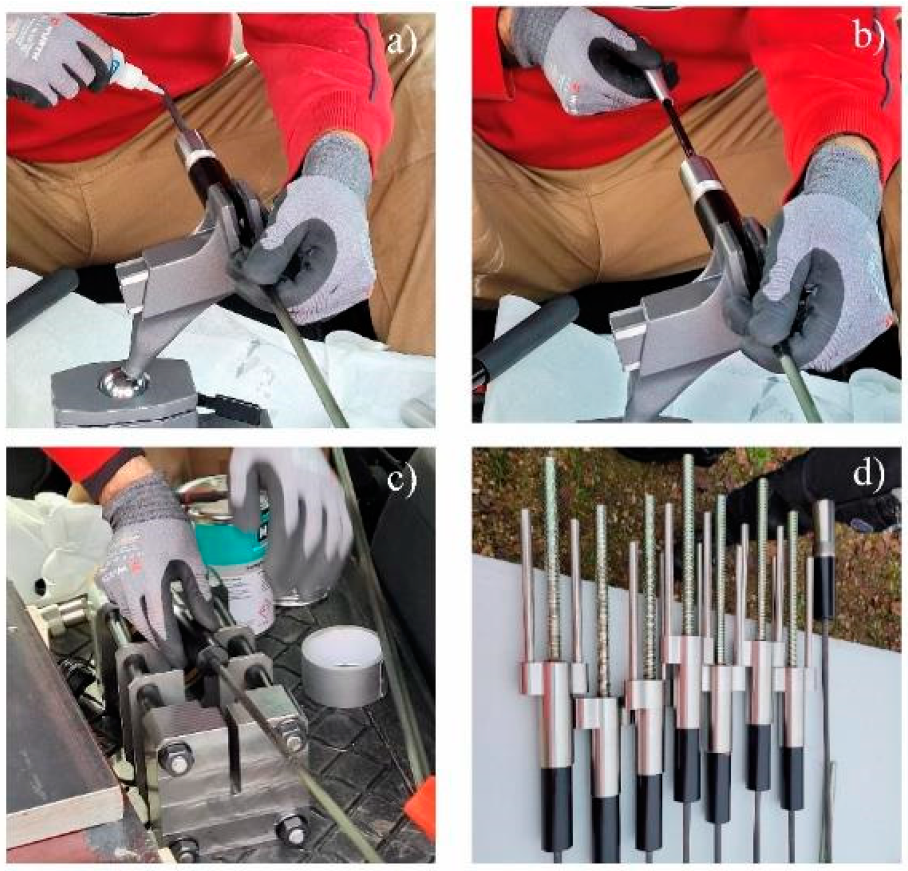
Assembling of the CFRP anchors. Photographs by the authors. (a) Grinding the CFRP surface and lubricating the surface with thin, liquid, and fast-curing glue. (b) Mounting of the wedge (viii) on the 8 mm CFRP rod in the lubricated area, which is then assembled with the barrel (ix). (c) Pre-setting of the wedge into the barrel using approximately 120 kN. (d) The coupler with inner threads (vii) was assembled with the threaded bar (v) as well as the end-threaded counteracting torque pins (vi) and screwed onto the threaded barrel (ix). Photographs by S&P.
Figure 7.
Assembling of the CFRP anchors. Photographs by the authors. (a) Grinding the CFRP surface and lubricating the surface with thin, liquid, and fast-curing glue. (b) Mounting of the wedge (viii) on the 8 mm CFRP rod in the lubricated area, which is then assembled with the barrel (ix). (c) Pre-setting of the wedge into the barrel using approximately 120 kN. (d) The coupler with inner threads (vii) was assembled with the threaded bar (v) as well as the end-threaded counteracting torque pins (vi) and screwed onto the threaded barrel (ix). Photographs by S&P.

Figure 8.
Pre-stressing applied by torque to the end nut on the assembled CFRP anchor system.

Figure 9.
Cut grooves used for the strengthening system mounting. Photograph by S&P.

Figure 10.
Installation of the through going threaded bars. Photograph by S&P.

Figure 11.
FE-simulation of the ductile unit.

Figure 12.
Tension test performed on the anchor system. Photograph by the authors.

Figure 13.
Load deformation test curves.

Figure 14.
Translation of the linear regime (0.14 mm) and identification of the yielding threshold.

Figure 15.
Beam numbering used for the pre-stressing procedure.

Figure 16.
Site installation of the throughgoing threaded bar and pre-stressing of the system. Photograph by S&P.
Figure 16.
Site installation of the throughgoing threaded bar and pre-stressing of the system. Photograph by S&P.

Figure 17.
The final result of the applied strengthening. Photograph by S&P.


Table 1.
Material properties of the anchor system.
| Parameter | Value [MPa] |
|---|---|
| Recommended ult. Stress of the CFRP rod | 2200 1 |
| E-modulus CFRP tendon, Ecf | 160.000–170.000 1 |
| Stainless steel yield/tension strength of the anchor block parts, fy/fu | 235/700 1 |
| Steel yield/tension strength of the barrel, fy/fu | 235/340 1 |
| Aluminum (6082-T6, EN 573-3) yield/tension strength | 260/310 1 |
| Steel yield/tension strength of the threaded activation bar, fy,bar/fu,bar | 900/1000 1 |
1 Data provided by the manufacturer.
Table 2.
Properties of the flexible adhesive.
| Parameter | Values |
|---|---|
| Hardness | 60, Shore A (ISO 868) 1 |
| Failure stress | 3.0 N/mm2 (ISO 37) 1 |
| E-modulus | 3.0 MPa 1 |
| Extension at failure | 200% (ISO 37) 1 |
| Elasticity | +/−20% 1 |
| Curing | 2 mm/day (Environment dependent) 1 |
1 Data provided by manufacturer.
Table 3.
Probabilistic results, including design resistance and partial factor.
| Mean | COV | Characteristic Resistance, | ULS Design Resistance, (Rd,n) | Partial Factor, (γR) |
|---|---|---|---|---|
| 62.3 kN | 0.01 | 61.7 kN ( = 2.34) | 60.3 kN ( = 7.48) | 1.02 |
Table 4.
Measured pre-stressing values during Phase 1, measured in microstrain with kilonewtons in parenthesis. In the final pre-stressing level, initial values are given along with measurements after three hours.
Table 4.
Measured pre-stressing values during Phase 1, measured in microstrain with kilonewtons in parenthesis. In the final pre-stressing level, initial values are given along with measurements after three hours.
| Location | 10 kN, Measures με/(kN) | 25 kN, Measures με/(kN) | 55 kN, Measures με/με3; (kN/kN3) | |
|---|---|---|---|---|
| Beam 1 | Ø (A) | 1269 (10.2) | 3189 (25.6) | 6867/6785; (55.2/54.6) |
| V (B) | 1185 (9.5) | 3196 (25.7) | 6852/6743; (55.1/54.2) | |
| Beam 2 | Ø (A) | 1211 (9.7) | 3102 (24.9) | 6877/6821; (55.3/54.9) |
| V (B) | 1187 (9.5) | 3069 (24.7) | 6841/6696; (55.0/53.9) | |
| Beam 3 | Ø (A) | 1281 (10.3) | 3161 (25.4) | 6870/6762; (55.3/54.4) |
| V (B) | 1248 (10.0) | 3200 (25.7) | 6882/6795; (55.3/54.6) | |
| Beam 4 | Ø (A) | 1226 (9.9) | 3091 (24.9) | 6877/6780; (55.3/54.5) |
| V (B) | 1215 (9.8) | 3142 (25.3) | 6883/6804; (55.4/54.7) | |
| Beam 5 | Ø (A) | 1354 (10.9) | 3116 (25.1) | 6847/6748; (55.1/54.3) |
| V (B) | 1278 (10.3) | 3141 (25.3) | 6844/6780; (55.0/54.5) |
Table 5.
Initial three-hour strain value of phase 1 (με3) compared to measured value after three weeks.
Table 5.
Initial three-hour strain value of phase 1 (με3) compared to measured value after three weeks.
| Location | 55kN, Measures με3/μεw (kN3/kNw) | Difference με3-μεw/(kN3-kNw) | |
|---|---|---|---|
| Beam 1 | Ø (A) | 6785/6666 (54.6/53.6) | 119/(1.0) |
| V (B) | 6743/6582 (54.2/52.9) | 161/(1.3) | |
| Beam 2 | Ø (A) | 6821/6758 (54.9/54.3) | 63/(0.5) |
| V (B) | 6696/6545 (53.9/52.6) | 151/(1.2) | |
| Beam 3 | Ø (A) | 6762/6568 (54.4/52.8) | 194/(1.6) |
| V (B) | 6795/6627 (54.6/53.3) | 168/(1.4) | |
| Beam 4 | Ø (A) | 6780/6630 (54.5/53.3) | 150/(1.2) |
| V (B) | 6804/6749 (54.7/54.3) | 55/(0.4) | |
| Beam 5 | Ø (A) | 6748/6648 (54.3/53.5) | 100/(0.8) |
| V (B) | 6780/6750 (54.5/54.3) | 30/(0.2) |
Table 6.
Final pre-stressing magnitudes just before adhesive bonding.
| Location | 55kN, Measures με3/μεw (kN3/kNw) | |
|---|---|---|
| Beam 1 | Ø (A) | 6899/55.5/1104 |
| V (B) | 6938/55.8/1110 | |
| Beam 2 | Ø (A) | 6861/55.2/1098 |
| V (B) | 6869/55.2/1099 | |
| Beam 3 | Ø (A) | 6846/55.1/1095 |
| V (B) | 6963/55.9/1114 | |
| Beam 4 | Ø (A) | 6938/55.8/1110 |
| V (B) | 6888/55.4/1102 | |
| Beam 5 | Ø (A) | 6863/55.2/1098 |
| V (B) | 6924/55.7/1108 |
Publisher’s Note: MDPI stays neutral with regard to jurisdictional claims in published maps and institutional affiliations. |
© 2022 by the authors. Licensee MDPI, Basel, Switzerland. This article is an open access article distributed under the terms and conditions of the Creative Commons Attribution (CC BY) license (https://creativecommons.org/licenses/by/4.0/).
Share and Cite
MDPI and ACS Style
Schmidt, J.W.; Sørensen, J.D.; Christensen, C.O. In Situ Concrete Bridge Strengthening Using Ductile Activated NSMR CFRP System. Buildings 2022, 12, 2244. https://doi.org/10.3390/buildings12122244
AMA Style
Schmidt JW, Sørensen JD, Christensen CO. In Situ Concrete Bridge Strengthening Using Ductile Activated NSMR CFRP System. Buildings. 2022; 12(12):2244. https://doi.org/10.3390/buildings12122244
Chicago/Turabian StyleSchmidt, Jacob Wittrup, John Dalsgaard Sørensen, and Christian Overgaard Christensen. 2022. "In Situ Concrete Bridge Strengthening Using Ductile Activated NSMR CFRP System" Buildings 12, no. 12: 2244. https://doi.org/10.3390/buildings12122244
Note that from the first issue of 2016, this journal uses article numbers instead of page numbers. See further details here.