
Experimental and Numerical Study on Steel Fiber Concrete under Blast Loading
1
School of Civil Engineering, Hunan University, Changsha 410082, China
2
Civil Engineering Inspection and Test Limited Company of Hunan University, Changsha 410082, China
*
Author to whom correspondence should be addressed.
Buildings 2022, 12(12), 2119; https://doi.org/10.3390/buildings12122119
Submission received: 8 November 2022
/
Revised: 25 November 2022
/
Accepted: 28 November 2022
/
Published: 2 December 2022
(This article belongs to the Collection Advanced Concrete Materials in Construction)
Abstract
:In this paper, 30 SFRC (Steel Fiber Reinforced Concrete) spindle specimens with different steel fiber contents were subjected to static loading tests and blast wave loading tests on spindle specimens with different steel fiber contents using a self-developed planar blast wave loading device (a new type of patent recognized by the State Intellectual Property Rights). The dynamic response, impact performance and damage mode of Steel Fiber Reinforced Concrete under blast loading were investigated. The experimental results show that with the increase of steel fiber content (within 2%), the strength of the Steel Fiber Reinforced Concrete increases slightly. The flatter the falling section of the stress-strain curve, the better the energy absorption effect. With the increase of explosive equivalent(24 g RDX and 36 g RDX), the more obvious the strain rate effect, the greater the increase of peak stress, and the SFRC with 2% steel fiber content has the best energy absorption effect. Furthermore, the dynamic response of SFRC spindle specimens was numerically simulated using the improved K&C material model with LS-DYNA explicit finite element dynamic analysis software. The results verify the validity and reliability of the improved K&C material model.
1. Introduction
As the world’s population continues to grow and the desire for scarce resources increases, the risk of large-scale, high-precision, high-powered warfare continues to rise! The power of unmanned aerial devices for precise positioning poses a serious challenge to protective engineering in warfare. The optimization of blast-resistant protective engineering for warfare purposes has received much attention. With the accelerating pace of industrial development, SFRC has gained the attention of scholars and experts in the fields of construction (bridge engineering, airport and port engineering), defense and military as well as academic research because of its high crack resistance, good elongation, excellent energy dissipation and energy absorption, and good impact resistance [1,2,3].
Many scholars have added different fibers to concrete for reinforcement. They usually include glass fibers [4,5], organic fibers [6,7], carbon fibers [8,9,10], synthetic fibers [11] and steel fibers [12,13,14,15,16], etc. And some scholars have conducted experimental and numerical simulations to compare glass/epoxy composite glass panels [17]. Zhao [18] and Zhang [19] proposed several different types of composite shields that can improve explosion resistance while maintaining light weight, and experimental and theoretical analyses were carried out. Steel fiber is one of the most preferred materials due to its wide availability and relative cheapness and better engineering economic value. Some studies have shown that the compressive strength as well as the modulus of elasticity of concrete is less affected by the steel fiber content, but it greatly enhances the performance of concrete after cracking with good resistance to blast local dislodgement [20,21,22].
As early as the 1940s, scholars from various countries, represented by the US and the USSR, successively mixed steel fiber of different shapes and proportions into plain concrete and studied its crack resistance and wear resistance. In the later part of the last century, in Asia, Europe and the United States, SFRC has been used in airport projects and highway pavement projects [22,23,24]. SFRC exhibited greater strength in direct tensile experiments [25], and scholars from various countries have further investigated the effect of different types of steel fibers and different contents on SFRC beams [26,27,28]. Yang [29] et al. conducted compression and splitting tensile tests on steel fiber concrete slabs and investigated the dynamic response and damage modes of concrete slabs by explosion tests. At present, research on steel fiber high performance concrete under low and medium strain rate loading has been fruitful [30,31,32].Yehya et al. [33] used ABAQUS to model and validate the experimental results for several beams under blast conditions; Jacques E et al. [34] studied lapped reinforced concrete beams at high strain rates. Li et al. [35] further used two-dimensional finite element individuals to predict the blast response of the beam and compared it with the test. While research on Steel Fiber Reinforced Concrete under blast impact is limited in terms of data and experiments, and, due to the lack of design guidelines, there is a lack of in-depth understanding of the basic characteristics of Steel Fiber Reinforced Concrete under blast impact. The intrinsic structure of Steel Fiber Reinforced Concrete at high strain rates is also not well developed. Due to the difficulty of controlled blast testing, scholars have remained at the stage of single experimental studies or numerical simulations [36], lacking specific comparative analyses for verification.
In this paper, an electro-hydraulic servo testing machine was used to carry out uniaxial compressive static load tests. The planar blast wave loading system exploded SFRC spindle specimens with strength C40 and steel fiber content (Vf) of 0, 0.5%, 1%, 1.5% and 2% at the blast load. The dynamic response, impact properties and damage characteristics were systematically investigated using a combination of experimental analysis and ANSYS/LS-DYNA numerical simulations [37] based on a modified K&C material model [38,39,40]. The mechanical characteristic curves and damage characteristics were obtained experimentally. This paper is to provide valuable research methods and data for the application of SFRC blast-resistant structures in academic research fields and engineering fields, and also provide a basis for the further research.
2. Experimental Study
2.1. Specimen Preparation
2.1.1. Experimental Raw Materials
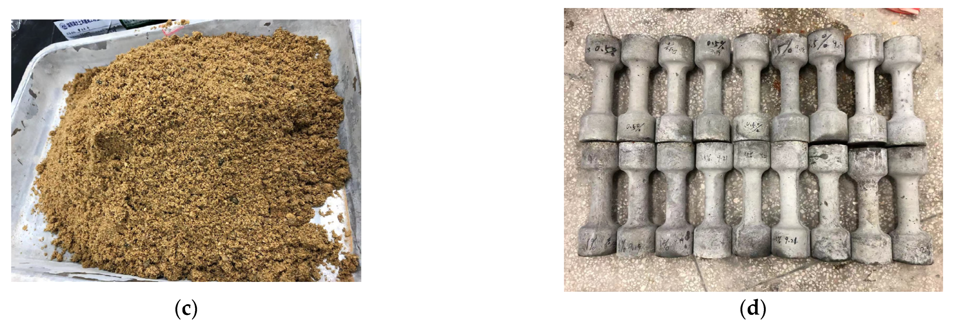
Cement. P-I 42.5 bulk cement; water. Natural tap water; fine aggregate: river sand, dry apparent density of 2580 kg/m3, maximum particle size of 5 mm, coarse aggregate using crushed stone, bulk density of 1480 kg/m3, maximum particle size of 10 mm, copper-plated straight steel fiber, yield strength of 780 MPa, density of 7750 kg/m3, diameter of 0.20 mm, length of about 12 mm. The specimens used in the test were spindle-shaped, manually mixed, compacted by vibrating table, and demolded after 24 h. After demolding, the specimens were immediately put into a standard maintenance room at 20 °C ± 3 °C and 95% or more humidity. See Figure 1 for specific materials used.
2.1.2. SFRC Mix Ratio
Table 1 shows the mix ratios of the materials used.
2.2. Quasi-Static Experimental Device and Principle
Electro-hydraulic servo testing machine: servo system is automatic control system which use a mechanical position or angle as the control range. In the electro-hydraulic servo pressure testing machine, the servo control system is used to control the piston movement of the loading cylinder position and movement speed. Electro-hydraulic servo test system can complete the conventional single-axis compression test, three-axis compression test, etc. In the quasi-static uniaxial compression test, three specimens of different steel fiber content were used in each group. The uniaxial compression test allows the compressive strength and the damage pattern of the SFRC specimens to be obtained directly, using an electro-hydraulic servo tester to obtain the time course of the pressure on the SFRC axis.
2.3. Plane Blast Wave Experimental Device and Principle
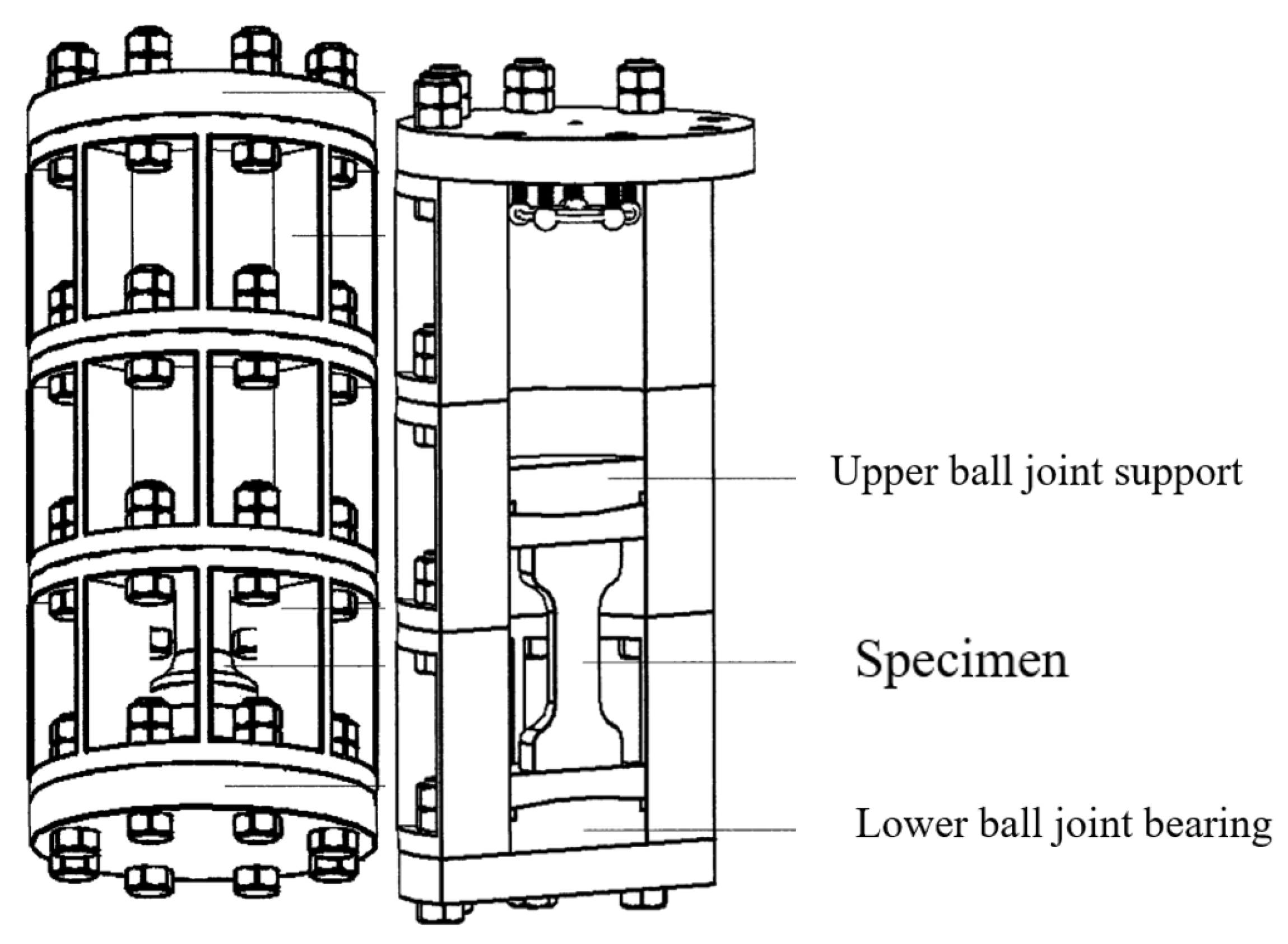
A self-developed planar blast wave loading device [41] (a new type of patent recognized by the State Intellectual Property Rights) as shown in Figure 2, was used to perform blast shock wave loading tests on the experimentally designed spindle specimens. The principle is: to perform multi-point simultaneous detonation through tandem detonation simultaneously detonating reticulated detonating cord; to obtain a plane blast wave conditioned by a wave guide tube; and after a certain distance through the impact plate (upper ball hinge) on the specimen loading which can achieve uniform symmetric loading effect, and fully and truly reflect the actual application of the specimen by high-speed impact loading in the high strain rate state, thus, can effectively test the damage characteristics and mechanical properties of concrete materials under high strain rate loading.
The advantage of this is that it overcomes the limitations on specimen size and length in the Hopkinson experiment [42] favoured by most authors. In SHPB (Split Hopkinson Pressure Bar), one-dimensional stress waves are used to cause concrete to be damaged under high strain rate conditions. If the diameter of the rod is too large, the spatial transmission characteristics of the waves cause different fluctuation characteristics at the interface of the input rod, which can lead to uneven stresses being applied to the concrete specimens.
2.4. Experimental Data Acquisition
The piezoelectric transducer gauge is mounted on the bottom cover of the axial explosion chamber. Experimental setup with INV3062T2 dynamic strain data acquisition instrument, INV1861A strain conditioner and COINV DASP V11 software system. Blast/shock loads are characterized by the short duration of the load action, which is the significant changes in kinematic parameters (displacement, velocity, acceleration) on short time scales measured in milliseconds (ms), microseconds (us) or even nanoseconds (ns). Under such dynamic loading conditions, the micro-elements of the medium are in a dynamic process that changes rapidly with time, and this data acquisition system is capable of.
Under such dynamic loading conditions, the micro-elements of the medium are rapidly changing and the data acquisition system INV3062T2 can acquire a wide range of physical signals such as noise, shock, strain, pressure and voltage under distributed, multi-point, long-range or wirelessly transmitted vibration conditions. The acquisition frequency is up to 51.2 kHz and, together with the DASP software, forms a high-performance data acquisition and signal processing system with more than 100 advanced technologies.
The INV1861A portable 8-channel strain conditioner with power conversion, bridge voltage supply, signal amplification, low-pass filtering, pre-balance, program control and voltage output provides a qualified voltage signal for subsequent analysis and recording equipment. It can be widely used to detect foundation subsidence, soil pressure and stress, strain, load and displacement of large engineering structures on railways, roads and bridges.
The DASP platform is made up of a dynamic test section and signal analysis software, which includes dozens of test and analysis modules, including signal oscilloscope acquisition, signal generation and DA output, and basic signal analysis. Different platforms contain different combinations of modules, which are divided into three main approaches during the sampling process. The oscilloscope acquisition part of the signal can be sampled continuously in large volume, with triple-think sampling (i.e., sampling, oscilloscope and spectrum analysis at the same time, oscilloscope acquisition and analysis at the same time); the instrument system flow for dynamic measurements is shown in Figure 3.
3. Experimental Results and Analysis
3.1. Quasi-Static Experimental Results
The basic mechanical parameters of Steel Fiber Reinforced Concrete and plain concrete (Vf = 0%) were obtained by uniaxial compression test as shown in Table 2.
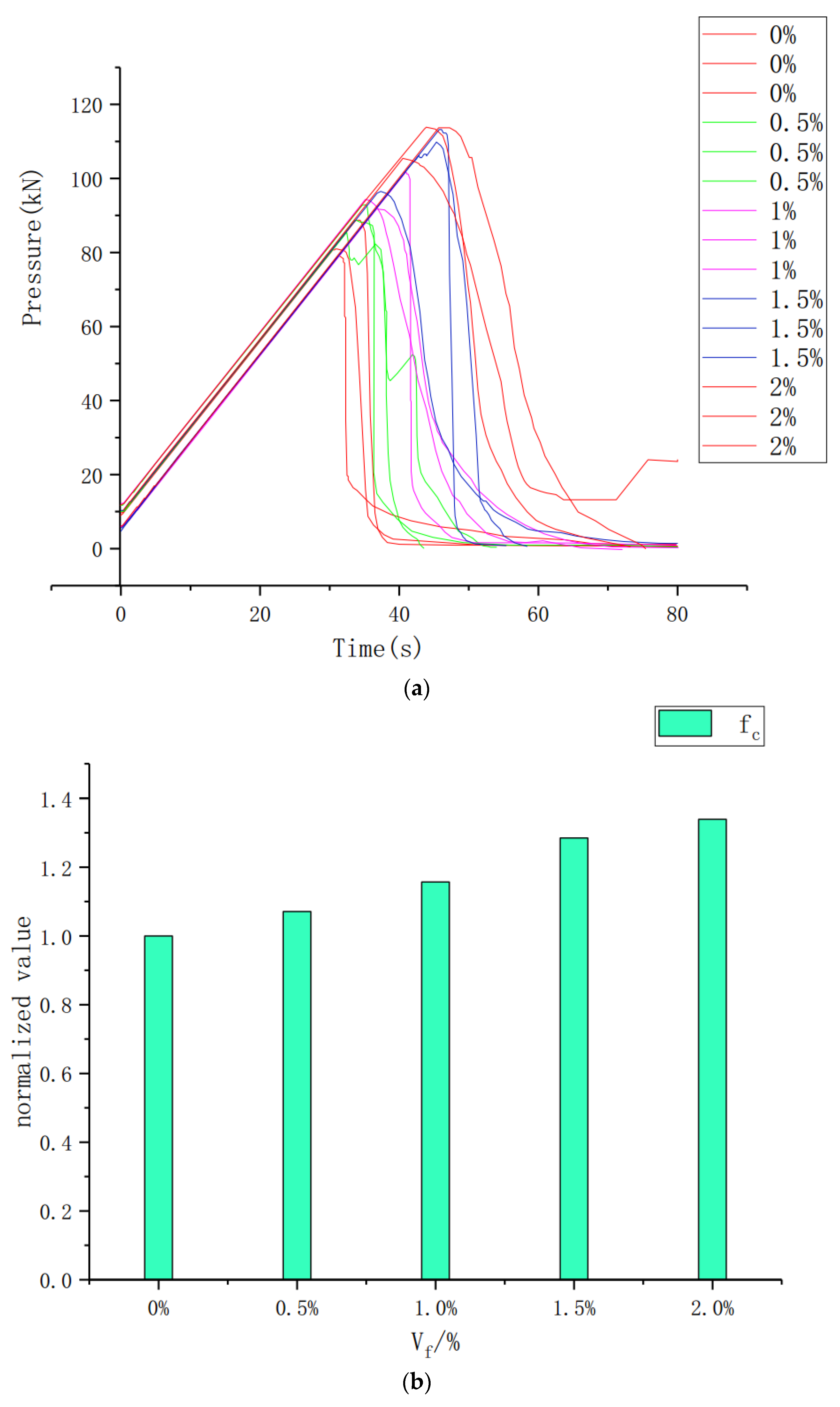
After testing, the static compressive strengths of SFRC with steel fiber content of 0%, 0.5%, 1%, 1.5%, and 2% are: 42.24 MPa, 45.26 MPa, 48.87 MPa, 54.27 MPa, 56.54 MPa, respectively. The value of the specimen is slightly larger than the strength of C40 concrete in the current specification. The uniaxial compressive pressure time-history curve of the spindle specimen with different steel fiber content is shown in Figure 4 and the relationship between the dimensionless parameter value fc and the steel fiber content as shown in Figure 4, where fc represents the ratio of static compressive strength of different steel fiber content to 0% steel fiber content.
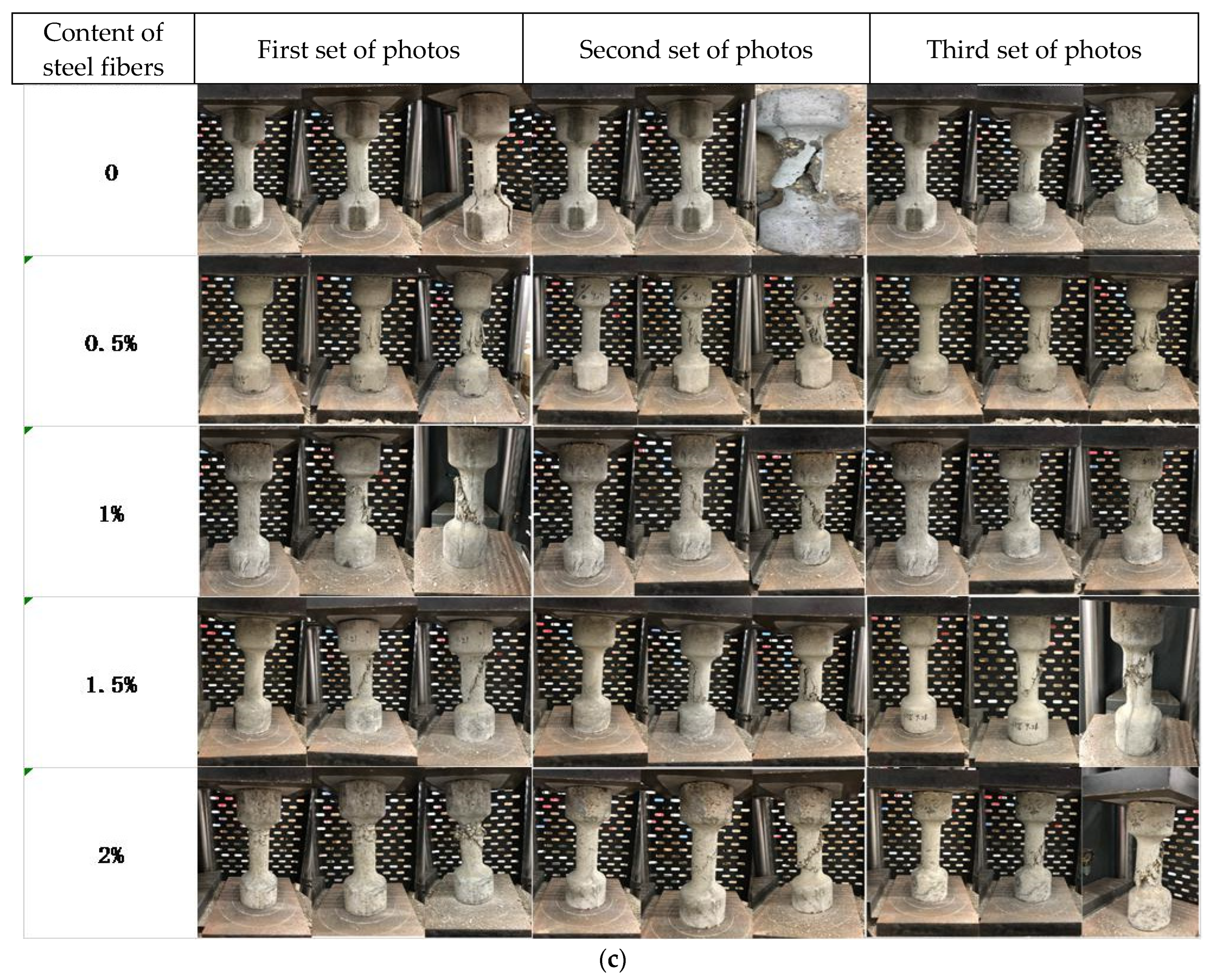
During the static load experiment, first install the specimen into the loading system, start the oil pump to load the specimen, set the loading speed to 0.3 MPa/s (2.355 kN/s); When the specimen loses its strength, the loading is terminated; the loading table is cleaned, and the next set of specimens are loaded. After the specimen is fixed for preloading, the pressure of the specimen reaches its peak value and the specimen loses its strength completely. The fracture process and crack development of the lower specimen; the photo of the quasi-static test results is shown in Figure 4.
3.2. Explosion Plane Wave Experiment
3.2.1. Sensor Development
In the study of the supporting facilities for the plane blast wave loading device, a pressure sensor for use with the plane blast wave loading device was studied. The sensor uses the principle of metal pressure contraction deformation to estimate the cross-sectional area required for the mechanical behavior of Q235 steel by combining the static compressive strength of the spindle under quasi-static experiments with a dynamic enhancement factor. First, the transducer was made according to the design drawing (see Figure 5a), and the surface of the specimen was polished, cleaned, and positioned. Then, a wire grid model BFH1K-3BB (see Figure 5b) was attached to the abdomen of the transducer, and the grid was arranged horizontally and vertically at 90 degrees. The sensor was calibrated by the pressure tester several times during the experiment (see Figure 5c) until the sensor stress-strain relationship was stable, forming a one-to-one data sheet for later data analysis. The physical sensor is shown in Figure 5d below.
3.2.2. Plane Blast Wave Experiment
The key to this experimental loading is that the plane blast wave loading device is loaded with different explosive equivalents and detonated synchronously with detonators, and the wave guide tube forms one-dimensional stress waves with different high strain rates. The experiments were conducted with 24 g and 36 g of black gold (RDX) explosives, respectively, and the pressure time profiles were measured by a dynamic strain acquisition system. The objectives of the experimental study were: (1) To study the data of 12 sets of SFRC spindle specimens with different steel fiber contents with constant explosive equivalents, and to investigate the effects of steel fiber contents on the impact resistance, blast resistance, ductility of stress peak and stress-strain drop section curves, and energy absorption performance of SFRC. (2) The explosive equivalents were varied on the basis of 6 groups of specimens with the same steel fiber content, respectively. Study the strain rate effect, stress peak, impact and blast resistance, energy dissipation and energy absorption of SFRC under different high-speed strain rate loading; the test site pictures are shown in Figure 6.
3.3. Explosion Plane Wave Experimental Results
The experimental simulation results to calculate the plane explosion wave experimental explosive equivalent, the experimental explosive used for the black gold (RDX), its power is about 1.5 times the TNT; experimental testing, in 24 g, 36 g black gold conditions, the steel fiber content of 0%, 0.5%, 1%, 1.5%, 2% of the plane explosion wave load peak pressure is shown in Table 3; pressure time curve is shown in Figure 7.
After testing, the SFRC compressive strengths of 24 g of black gold (RDX) detonated by detonator with steel fiber contents of 0%, 0.5%, 1%, 1.5%, 2%, respectively, are as follows: The compressive strength of SFRC was 69.99 MPa, 76.39 MPa, 83.68 MPa, 89.48 MPa, 97.83 MPa, and 36 g of black gold (RDX).The compressive strengths of SFRC with steel fiber content of 0%, 0.5%, 1%, 1.5%, and 2% under the action of 36 g of black sorghum (RDX) were 111.38 MPa, 120.34 MPa, 127.19 MPa, 127.19 Mpa, 128.73 MPa, and 139.41 MPa respectively. The dynamic strengthening factors are shown in Figure 8.
4. Numerical Simulation of the Blast Resistance of Steel Fiber Reinforced Concrete
4.1. LS-DYNA Geometric Model
The validity and reliability of the improved failure strength surface parameter model, damage model, and compressive dynamical enhancement factor model are simulated for the Steel Fiber Reinforced Concrete spindle specimens under blast load. The numerical simulations are as follows: spindle body specimens with steel fibers of 0%, 0.5%, 1%, 1.5%, and 2%, respectively, are placed in a planar blast wave loading device with symmetric restraints applied on their symmetry surfaces. The explosive and SFRC plates were discretized using SOLID164 unit with a discretization element size of 2 mm and a single-point Gaussian integral Lagrangian algorithm. The SFRC spindle specimens are coupled with *EOS_TABULATED_COMPACTION equation of state using a modified K&C material model.
In this study, the 1/4 computational model for the SFRC spindle explosion experiment is shown in Figure 9, using the keyword (*BOUNDARY_SPC_SET) on the symmetry surface of the model to apply surface constraints, using SOLID164 solid unit for rigid mat, SFRC spindle specimen for unit discretization, size 2 mm, using a single-point Gaussian integral Lagrangian algorithm, single-point integration of the display unit can be well applied to the explosion event caused by large deformation, material failure and contact and other high-precision nonlinear problems.
4.2. Introduction to LS-DYNA Algorithm
Finite unit method, finite volume method and finite difference method have been developed for medium unit. In engineering, for discontinuous media such as concrete and fractured rocks, the algorithms developed discrete element method, finite block method, and numerical manifold method. At this stage, the methods used for analysis using coordinate systems are mainly arbitrary Lagrangian method, Eulerian method (ALE) and coupled Lagrangian and Eulerian methods (CLE), as well as the smooth mass dynamics method (SPH), which has been widely used in the field of explosion analysis in recent years. The above methods allow simpler implementation of complex intrinsic behavior and more accurate material damage calculations for materials under explosive loading.
4.3. K&C Material Model for Dynamic Damage of LS-DYNA Concrete
K&C material model [43,44,45,46,47,48]: the establishment of: Malvar et al. extracted independent failure yield surfaces based on the Pseudo-Tensor model (*MAT_16), modified the cut-off pressure values, established three fixed failure strength surfaces, modified the shear modulus and defined the relationship between the triaxial tensile to compressive ratio and pressure.
Yin, Huawei [49] et al. improved the Malvar model. They improved the model with three fixed failure strength surfaces, modified the damage mechanism, which into the SFRC’s dynamic enhancement factor model. Due to the dynamic generation of the original K&C material model since, the strength surface parameters of ordinary concrete were used. In the improved model, the strength surface parameters applicable to high-strength, highly energy-absorbing concrete such as SFRC were used based on 96 sets of SFRC triaxial compression experimental data, and this measure greatly improved the ability of the model to express the toughness, ductility, and energy absorption of high-strength, highly energy-absorbing concrete such as SFRC. The ability to express the mechanical behavior of the strain-softening section is improved.
4.3.1. Improvement of Maximum Strength Surface Parameters
Malvar defined three independent failure strength surfaces using compression meridians with a maximum strength surface Δσm, an initial yield strength surface Δσy, and the residual strength surface Δσr
where: ai, aiy, aif (i = 0,1,2), a set of parameters obtained from the triaxial compression test of concrete; hydrostatic pressure p = (σ1 + σ2 + σ3)/3, where σ1, σ2, σ3 are the 1st, 2nd, and 3rd principal stresses, respectively; failure strength surface deflection stress:
It was found that the volume fraction of steel fibers has a large effect on the triaxial compression strength of SFRC. Therefore, based on the original maximum strength surface, Yin [49] et al. used the least two-layer method to establish a new parametric model of the maximum strength surface based on a large amount of experimental data.
The maximum strength surface parameters a0, a1, and a2 of SFRC are given in the following equation
4.3.2. Modified Damage Mechanisms
The addition of steel fibers changes the damage evolution mechanism of the original concrete. In order to better express the excellent ductility, toughness and high energy absorption capacity of SFRC, to improve the defect of too fast damage evolution of the original model, and to accurately express the process of damage evolution due to plastic shear strain and plastic volume strain, the damage evolution function is modified as follows.
where α is the constant of the control strain hardening section, αc and αd are the constants of control the strain softening section, and λm is the peak effective plastic strain, λ is the effective plastic strain.
4.3.3. Calibration of Damage Parameters
The effective plastic strain accumulation function in the K&C material model is as follows [50]:
where: is the effective plastic strain increment; is the strain rate enhancement factor; is the uniaxial tensile strength; b1 and b2 are the mechanical behaviors involved in controlling the uniaxial compression and tensile softening sections, respectively.
4.3.4. Improved SFRC Dynamic Enhancement Factor Model
In this study, based on the CEB-FIP [50] compressive dynamic strengthening factor model, the SFRC compressive dynamic strengthening factor (CDIF) model was improved by introducing the fiber volume fraction factor and modifying the transition strain rate, and conducting least-squares linear regression analysis for 122 experimental data sets. (CDIF) model with the following functional relationship equation.
where: is the transition strain rate, ; is the steel fiber volume fraction factor
is the model of improved SFRC tensile dynamic enhancement factor (TDIF) is the reference strain rate. The relationship equation is as follows.
where: is the dynamic tensile strength, is the static tensile strength, the reference strain rate ; ; is the current strain rate, ; .
4.3.5. TNT Explosive Model
The TNT explosive is modeled as a high-energy explosive material model (*MAT_HIGH_EXPLOSIVE_BURN) with the *EOS_JWL equation of state. The material parameters of the explosives are shown in Table 4.
In the table: is the mass density, is the explosion velocity, is the Chapman-Jouget pressure. The JWL equation of state defines the pressure as:
where: p is the pressure generated by explosive products; A, B, R1, R2, ω are status parameters; V is the specific volume; E0 is the energy density. The values of the equation of state parameters for TNT explosives are shown in Table 5.
4.3.6. Material Model for Steel Fiber Concrete
The process of compression and even damage under the action of high strain rates such as explosive loads is very complex, the use of a reasonable and reliable material model is essential, the general material model is mostly applicable to the experiments or low speed or ordinary concrete, in the explosive load and other high strain rates by the action of the SFRC material models are few and far between, this paper uses the original K&C material model to improve the maximum strength surface, initial strength surface, residual strength surface and other parameter values, damage evolution function, damage scale factor, DIF model; can better predict the dynamic response of SFRC and other high-strength concrete components, and capture the mechanical behavior of the SFRC spindle to receive the whole process of blast shock wave penetration; improved K&C material The main parameters of the model are shown in Table 6 and Table 7.
In the table: ρ is the mass density of steel fiber reinforced concrete, fC is the uniaxial compressive strength, ft is the uniaxial tensile strength, lw is the local crack width, v is the Poisson’s ratio, b1 is the compression damage parameter, b2 is the tensile strength Damage parameters, b1 is the volume damage parameter, a0, a1, a2 are the maximum strength surface parameters, a0y, a1y, a2y are the initial strength surface parameters, a1f, a2f are the residual strength surface parameters.
4.3.7. Air Material Model
In the simulation, the air domain material model of the blast chamber in the waveguide in the simulation uses *MAT_NULL, coupling *EOS_LINEAR_POLYNOMIAL equation of state. This equation of state is used to define a fluid material model such as air, and requires input parameters including: density, modulus of elasticity, Poisson’s ratio, pressure cutoff (less than 0.0), dynamic viscosity coefficient, relative volume for dilatational erosion process (ignored by 0), and relative volume for compressive erosion process (ignored by 0). The coefficients C0 to C6 of the equation of state, the initial internal energy and initial relative volume, and the air material model parameters are shown in Table 8 below.
4.3.8. The Simulation Results of SRRC Spindle Body by Explosion Shock Wave
The peak stresses (Fm) of the spindle specimens under different explosive equivalent (D0) conditions are shown in Table 9 below.
Due to the low controllability of the explosion test, through multiple numerical simulations, the explosive equivalent required for the specimen to yield under the explosion load was gradually approached, and after several adjustments, the steel fiber content was 0 under the action of 31.99 g and 47.99 g TNT, respectively. 0%, 0.5%, 1%, 1.5%, 2% SFRC energy time history curve, stress time history curve, (as shown in Figure 10), the numerical simulation of SFRC specimen under plane blast wave loading.
5. Results and Discussion
Through the collation of experimental data; through the quasi-static experimental, numerical simulation results of comparative analysis, steel fiber concrete has a significant strain rate effect. This phenomenon can be explained by the fact that the main cause of concrete damage is the appearance and development of cracks. As the blast impact velocity increases, the number of cracks increases and the appearance of cracks requires a large amount of energy. Due to the extremely short duration of the blast impact load, the crack expansion rate is much smaller than the stress expansion rate. The concrete does not have enough time to accumulate energy, so the energy can only be absorbed by increasing the stress. This leads to an increase in dynamic strength as the strain rate increases.
Through the quasi-static experiments in Table 2 and Figure 4, the research results show that under static loading, the mechanical properties of SFRC with the content of steel fibers are characterized: with the increase of fiber content, the compressive strength of SFRC increases, and the steel fiber content is 2% is about 33% higher than the steel fiber content of 0%.And this finding proves the study of Semsi et al. [40].
Combined with Table 2 and Table 3 and Figure 4 and Figure 7, the experiments were conducted under quasi-static loading, as well as explosive equivalent of 24 g RDX (approximately equal to 31.99 g TNT), 36 g RDX (approximately equal to 47.99 g TNT), and comparative analysis by plane blast wave loading; the results showed that the SFRC strain rate effect was obvious, and the dynamic enhancement factor under the blast load of 24 g RDX loading increased with The results showed that the SFRC strain rate effect was obvious, and the dynamic enhancement factor was stable from 0% to 2.0% with the steel fiber content of 24 g RDX loading at about 1.6. With the increase of explosive equivalent, the DIF value of SFRC increased with the increase of explosive equivalent (loading rate) from 0% to 2.0% and stabilized at about 2.4 with the steel fiber content at 36 g RDX.
Through a comprehensive analysis of the plane blast wave experimental data and LS-DYNA numerical analysis of the two data results, under the blast load, due to the blast impact time is very short, SFRC has more crack formation, so the steel fiber doping for the blast impact performance, and with the increasing amount of steel fiber doping, blast impact resistance enhanced; stress-strain curve in the Stress softening section (falling section) is more gentle, showing that SFRC has better toughness, ductility and more excellent energy absorption properties.
By analyzing the data from the blast side (sensor No. 1) and the support side (sensor No. 2) of the specimen in the plane blast wave experiment (shown in Figure 7), the data showed that the blast shock wave propagated in the specimen at a speed of about 0.02 ms; the stress peak on the support side of the specimen was reduced by about 10% compared with the blast side.
The experiments were conducted using a modified K&C material model and a comprehensive comparison between the experimental data of plane blast wave and the numerical analysis data of LS-DYNA. The experiments verify the validity of the numerical simulation results and further show that the improved K&C material model has better applicability, effectiveness and high reduction in the simulation of steel fiber concrete. In contrast to the prediction model proposed by Monjee K et al. [51], the use of conventional software simulation has better applicability and generality.
Obviously, we need to conduct more experimental studies on steel fiber concrete blast resistance test research in order to establish a large database for more in-depth quantitative analysis. Secondly, a large amount of experimental data is needed to calibrate the material parameter model. In the existing material model, there are still places such as damping, incomplete parameters, etc. The study of a complete set of material intrinsic model will help the research.
6. Conclusions
The purpose of the experiment was to investigate the effect of steel fiber volume fraction and blast loading rate on dynamic properties under blast loading. The research and finite element analysis of this experiment are reviewed. In this paper, SFRC specimens with different conditions were studied by using a planar blast wave device loading and LS-DYNA software simulation for comparative analysis, they were: five groups with different steel fiber contents (0%, 0.5%, 1.0%, 1.5% and 2.0% volume fraction) and different explosive equivalents (24 g RDX and 36 g RDX). In this paper, the mechanical properties of SFRC were analyzed in detail under different steel fiber content conditions and different explosive equivalent loading, and the strain rate effect and impact properties of SFRC were explained, and the following conclusions were drawn:
- (1)
- With the increase of explosive equivalent (increase of strain rate), the dynamic peak stress and corresponding strain as well as dynamic modulus of elasticity of steel fiber concrete are increased, and the strain rate effect is obvious
- (2)
- Under the same conditions of steel fiber content, as the explosive equivalent (blast loading rate) increases, the strain rate effect is obvious, the peak stress is significantly increased, and the energy absorption effect is better. For example, 2% steel fiber concrete at 36 g RDX increased the peak pressure by 42% compared to 24 g, while also absorbing more energy.
- (3)
- Under the same conditions of explosive equivalent (blast loading rate), with the increase in steel fiber content, the compressive strength of steel fiber concrete has a small increase (15% increase in 2% steel fiber concrete compared to 0% at 36 g RDX). At the same time, the splash phenomenon is effectively reduced and anti-blast performance significantly improved.
- (4)
- The dynamic response of SFRC spindle specimens loaded by planar blast wave device was simulated by LS-DYNA software, The damage pattern of the specimen is basically the same as the simulation results; meanwhile, the error of the simulated peak pressure and the actual pressure are within 5%. It can show that the improved K&C material model can accurately represent the dynamic response of SFRC subjected to blast loading.
Author Contributions
Conceptualization, H.Y. and Y.O.; methodology, H.Y.; software, Y.O.; validation, H.Y. and Y.O.; formal analysis, H.Y.; investigation, Y.O.; resources, H.Y.; data curation, H.Y.; writing—original draft preparation, Y.O.; writing—review and editing, H.Y.; visualization, Y.O.; supervision, Y.O.; project administration, H.Y.; funding acquisition, H.Y. All authors have read and agreed to the published version of the manuscript.
Funding
This research received no external funding.
Institutional Review Board Statement
Not applicable.
Informed Consent Statement
Not applicable.
Data Availability Statement
Not applicable.
Acknowledgments
The authors acknowledge the support from the School of Civil Engineering, Hunan University and Civil Engineering Inspection and Test Limited Company of Hunan University.
Conflicts of Interest
The authors declare no conflict of interest.
References
- Aoude, H.; Dagenais, F.P.; Burrell, R.P.; Saatcioglu, M. Behavior of ultra-high-performance fiber reinforced concrete columns under blast loading. Int. J. Impact. Eng. 2015, 80, 185–202. [Google Scholar] [CrossRef]
- Lee, D.H.; Hwang, J.H.; Ju, H.; Kang, S.K. Application of direct tension force transfer model with modified fixed-angle softened-truss model to finite element analysis of steel fiber-reinforced, concrete members subjected to shear. Comput. Concr. 2014, 13, 49–70. [Google Scholar] [CrossRef]
- Rajanpur, A.G.; Tolba, A.; Contestabile, E. Blast loading response of reinforced concrete panels reinforced with externally bonded GFRP laminates. Compos. Part B 2007, 38, 535–546. [Google Scholar] [CrossRef]
- Keleştemur, O.; Yildiz, S.; Gökçer, B.; Arici, E. Statistical analysis for freeze–thaw resistance of cement mortars containing marble dust and glass fiber. Mater. Des. 2014, 60, 548–555. [Google Scholar] [CrossRef] [Green Version]
- Kizilkanat, A.B.; Kabay, N.; Akyüncü, V.; Chowdhury, S.; Akça, A.H. Mechanical properties and fracture behavior of basalt and glass fiber reinforced concrete: An experimental study. Constr. Build. Mater. 2015, 100, 218–224. [Google Scholar] [CrossRef]
- Zhu, H.-B.; Yan, M.-Z.; Wang, P.-M.; Li, C.; Cheng, Y.-J. Mechanical performance of concrete combined with a novel high strength organic fiber. Constr. Build. Mater. 2015, 78, 289–294. [Google Scholar] [CrossRef]
- Swift, D.G. The use of natural organic fibres in cement: Some structural considerations. Compos. Struct. 1981, 602–617. [Google Scholar] [CrossRef]
- Wen, S.; Chung, D. Strain-sensing characteristics of carbon fiber-reinforced cement. ACI. Mater. J. 2005, 102, 244. [Google Scholar]
- Chen, B.; Liu, J. Damage in carbon fiber-reinforced concrete, monitored by both electrical resistance measurement and acoustic emission analysis. Constr. Build. Mater. 2008, 22, 2196–2201. [Google Scholar] [CrossRef]
- Hogancamp, J.; Grasley, Z. The use of microfine cement to enhance the efficacy of carbon nanofibers with respect to drying shrinkage crack resistance of portland cement mortars. Cem. Concr. Compos. 2017, 83, 405–414. [Google Scholar] [CrossRef]
- Caggiano, A.; Gambarelli, S.; Martinelli, E.; Nisticò, N.; Pepe, M. Experimental characterization of the post-cracking response in hybrid steel/polypropylene fiber-reinforced concrete. Constr. Build. Mater. 2016, 125, 1035–1043. [Google Scholar] [CrossRef]
- Bilodeau, K.; Sauzeat, C.; Di Benedetto, H.; Olard, F.; Bonneau, D. Laboratory and in situ investigations of steel fiber-reinforced compacted concrete containing reclaimed asphalt pavement. In Proceedings of the Transportation Research Board 90th Annual Meeting, Washington, DC, USA, 23–27 January 2011. [Google Scholar]
- Deng, F.; Ding, X.; Chi, Y.; Xu, L.; Wang, L. The pull-out behavior of straight and hooked-end steel fiber from hybrid fiber reinforced cementitious composite: Experimental study and analytical modelling. Compos. Struct. 2018, 206, 693–712. [Google Scholar] [CrossRef]
- Niu, D.; Jiang, L.; Bai, M.; Miao, Y. Study of the performance of steel fiber reinforced concrete to water and salt freezing condition. Mater. Des. 2013, 44, 267–273. [Google Scholar] [CrossRef]
- Li, B.; Xu, L.; Chi, Y.; Huang, B.; Li, C. Experimental investigation on the stress-strain behavior of steel fiber reinforced concrete subjected to uniaxial cyclic compression. Constr. Build. Mater. 2017, 140, 109–118. [Google Scholar] [CrossRef]
- Birely, A.C.; Park, P.; McMahon, J.A.; Shi, X.; Rew, Y. Fiber Reinforced Concrete for Improved Performance of Transportation Infrastructure; Report FHWA/AZ-18-705; U.S. Department of Transportation: Washington, DC, USA, 2018.
- Gunaryo, K.; Heriana, H.; Sitompul, M.R.; Hadi, B.K.; Kuswoyo, A. Experimentation and numeri-cal modeling on the response of woven glass/epoxy composite plate under blast impact loading. Int. J. Mech. Mater Eng. 2020, 15, 4. [Google Scholar] [CrossRef]
- Zhao, Z.; Zhang, B.; Zhou, J.; Chen, H.; Wang, B.; Zhou, Y. Quasi-far-field blast responses of hierarchical orthogrid-stiffened sheet molding compound (SMC) protective door structures. J. Eng. Struct. 2018, 168, 431–446. [Google Scholar] [CrossRef]
- Bei, Z.; Hh, B.; Qiang, Z.B.; Hfa, C. Blast responses of pultruded GFRP fluted-core sandwich panels: Testing and analyzing. Polym. Test. 2019, 79, 106047. [Google Scholar] [CrossRef]
- Wang, H.; Chen, H.; Zhou, Y.; Peng, W.; Fan, H. Blast responses and damage evaluation of cfrp tubular arches. Constr. Build. mater. 2019, 196, 233–244. [Google Scholar] [CrossRef]
- Wang, P.; Jiang, M.R.; Zhou, J.N. Spalling in concrete arches subjected to shock wave and CFRP strengthening effect. Tunn. Undergr. Sp. Technol. 2018, 74, 10–19. [Google Scholar] [CrossRef]
- Liu, S.F.; Zhou, Y.Z.; Zheng, Q. Blast responses of concrete beams reinforced with steel-GFRP composite bars. Structures 2019, 22, 200–212. [Google Scholar] [CrossRef]
- Kang, S.T.; Lee, B.Y.; Kim, J.-K.; Kim, Y.Y. The effect of fiber distribution characteristics on the flexural strength of steel fiber-reinforced ultra-high strength concrete. Constr. Build. Mater. 2011, 25, 2450–2457. [Google Scholar] [CrossRef]
- Xie, Y.J.; Qiang, F.; Zheng, K.R.; Qiang, Y.; Hao, S. Dynamic mechanical properties of cement and asphalt mortar based on shpb test. Constr. Build. Mater. 2014, 70, 217–225. [Google Scholar] [CrossRef]
- Kwan, A.K.H.; Chu, S.H. Direct tension behaviour of steel fibre reinforced concrete measured by a new test method. Eng. Struct. 2018, 176, 324–336. [Google Scholar] [CrossRef]
- Guertin-Normoyle, C. Blast Performance of Ultra-high Performance Concrete Beams Tested under Shock-Tube Induced Loads. Master’s Thesis, University of Ottawa, Ottawa, ON, Canada, 2018. [Google Scholar] [CrossRef]
- Algassem, O. Parameters Affecting the Blast Performance of High Strength Fibre Reinforced Concrete Beams. Master’s Thesis, University of Ottawa, Ottawa, ON, Canada, 2016. [Google Scholar]
- Algassem, O.; Li, Y.; Aoude, H. Ability of steel fibers to enhance the shear and flexural behavior of high-strength concrete beams subjected to blast loads. Eng. Struct. 2019, 199, 109611. [Google Scholar] [CrossRef]
- Yang, D.; Zhang, B.; Liu, G. Experimental Study on Spall Resistance of Steel-Fiber Reinforced Concrete Slab Subjected to Explosion. Int. J. Concr. Struct. Mater. 2021, 15, 23. [Google Scholar] [CrossRef]
- Nataraja, M.C.; Nagaraj, T.S.; Basavaraja, S.B. Reproportioning of steel fiber reinforced concrete mixes and their impact resistance. Cem. Concr. Res. 2005, 35, 2350–2359. [Google Scholar] [CrossRef]
- Mao, L.; Barnett, S.; Begg, D.; Schleyer, G.; Wight, G. Numerical simulation of ultra high performance fiber reinforced concrete panel subjected to blast loading. Int. J. Impact Eng. 2014, 64, 91–100. [Google Scholar] [CrossRef] [Green Version]
- Wang, Z.L.; Liu, Y.S.; Shen, R.F. Stress–Strain relationship of steel fiber-reinforced concrete under dynamic compression. Constr. Build. Mater. 2008, 22, 811–819. [Google Scholar] [CrossRef]
- Temsah, Y.; Jahami, A.; Khatib, J.; Sonebi, M. Numerical analysis of a reinforced concrete beam under blast loading. Constr. Build. Mater. 2018, 149, 02063. [Google Scholar] [CrossRef]
- Jacques, E.; Saatcioglu, M. High-Strain-Rate Response of Reinforced Concrete Lap-Spliced Beams. J. Struct. Eng. 2020, 146, 04019165. [Google Scholar] [CrossRef]
- Li, Y.; Aoude, H. Influence of steel fibers on the static and blast response of beams built with high-strength concrete and high-strength reinforcement. Eng. Struct. 2020, 221, 111031. [Google Scholar] [CrossRef]
- Fang, Q.; Zhang, J.H. Three-dimensional modelling of steel fiber reinforced concrete material under intense dynamic loading. Constr. Build. Mater. 2013, 44, 118–132. [Google Scholar] [CrossRef]
- Ls-Dyna. LS-DYNA Keyword User’s Manual, version 971; Livermore Software Technology Corporation: Livermore, CA, USA, 2010. [Google Scholar]
- Liao, L.; Zhao, J.; Zhang, F.; Li, S.; Wang, Z. Experimental study on compressive properties of SFRC under high strain rate with different fiber content and aspect ratio. Constr. Build. Mater. Nat. Sci. 2020, 261, 33–42. (In Chinese) [Google Scholar] [CrossRef]
- Zhang, S.; Zhang, C.; Liao, L. Investigation on the relationship between the steel fiber distribution and the post-cracking behaviour of SFRC. Constr. Build. Mater. 2019, 200, 539–550. [Google Scholar] [CrossRef]
- Yazıcı, Ş.; İnan, G.; Tabak, V. Effect of aspect ratio and volume fraction of steel fiber on the mechanical properties of SFRC. Constr. Build. Mater. 2007, 21, 1250–1253. [Google Scholar] [CrossRef]
- Wei, Y.H.; Xi, D.J.; Ke, J. Plane Blast Wave Loading Test Device. China. Utility Model Patents. 201921355667.8, 12 May 2020. [Google Scholar]
- Lo, T.S.; Zhao, P.J.; Lu, G. Using the split Hopkinson pressure bar to investigate the dynamic behavior of SFRC. Magaz. Concr. Res. 2003, 55, 183–191. [Google Scholar] [CrossRef]
- Lok, T.S.; Zhao, P.J. Impact response of steel fiber-reinforced concrete using a split hopkinson pressure bar. J. Mater. Civ. Eng. 2004, 16, 54–59. [Google Scholar] [CrossRef]
- Balendran, R.V.; Zhou, F.P.; Nadeem, A.; Leung, A.Y.T. Influence of steel fibers on strength and ductility of normal and lightweight high strength concrete. Build. Environ. 2002, 37, 1361–1367. [Google Scholar] [CrossRef]
- Mohammadi, Y.; Carkon-Azad, R.; Singh, S.P.; Kaushik, S.K. Impact resistance of steel fibrous concrete containing fibers of mixed aspect ratio. Constr. Build. Mater. 2009, 23, 183–189. [Google Scholar] [CrossRef]
- Abrams, D.A. Effect of rate of application of load on the compressive strength of concrete. J. ASTM Intern. 1917, 172, 364–377. [Google Scholar]
- Bhargava, J.; Rehnstrom, A. Dynamic strength of polymer modified and fiberreinforced concretes. Cem. Concr. Res. 1997, 7, 199–208. [Google Scholar] [CrossRef]
- Malvar, L.J.; Crawford, J.E.; Wesevich, J.W. A plasticity concrete material model for DYNA3D. Int. J. Impact Eng. 1997, 19, 847–873. [Google Scholar] [CrossRef]
- Wei, Y.H.; Ke, J.; Liao, Z. K&C model of steel fiber reinforced concrete slabs under impact and explosion loads. Chin. J. High Press. Phys. 2020, 34, 1–11. [Google Scholar] [CrossRef]
- Guo, Z.H. Strength and Deformation of Concrete—Experimental Basis and Constitutive Relationships; Tsinghua University Press: Beijing, China, 1997. [Google Scholar]
- Almustafa, M.K.; Nehdi, M.L. Machine learning prediction of structural response of steel fiber-reinforced concrete beams subjected to far-field blast loading. Cem. Concr. Compos. 2022, 126, 104378. [Google Scholar] [CrossRef]
Figure 1.
Material picture: (a) stone (b) steel fiber (c) sand (d) SFRC specimen.


Figure 2.
Plane wave explosive test device diagram.

Figure 3.
Instrumental system diagram for dynamic measurement.

Figure 4.
Quasi-static experimental results: (a) SFRC basic mechanical parameters; (b) The relationship between the dimensionless parameters of SFRC and steel fiber content; (c) The damage process of SFRC with different steel fiber content under uniaxial compression.
Figure 4.
Quasi-static experimental results: (a) SFRC basic mechanical parameters; (b) The relationship between the dimensionless parameters of SFRC and steel fiber content; (c) The damage process of SFRC with different steel fiber content under uniaxial compression.


Figure 5.
Sensor development process. (a) Sensor size (b) Strain gauges (c) Commissioning of sensors (d) Physical sensor.
Figure 5.
Sensor development process. (a) Sensor size (b) Strain gauges (c) Commissioning of sensors (d) Physical sensor.

Figure 6.
Plane explosion wave experiment sited.

Figure 7.
Time history curve of plane explosive wave pressure: (a) 0%SFRC pressure time course curve under 24 g RDX; (b) 0%SFRC pressure time history curve under 36 g RDX; (c) 0.5%SFRC pressure time course curve under 24 g RDX; (d) 0.5%SFRC pressure time history curve under 36 g RDX; (e) 1%SFRC pressure time course curve under 24 g RDX; (f) 1%SFRC pressure time history curve under 36 g RDX; (g) 1.5%SFRC pressure time course curve under 24 g RDX; (h) 1.5%SFRC pressure time history curve under 36 g RDX; (i) 2%SFRC pressure time course curve under 24 g RDX; (j) 2%SFRC pressure time history curve under 36 g RDX.


Figure 8.
Dynamical enhancement factor.

Figure 9.
1/4 LS-DYNA calculation model.

Figure 10.
Simulation results of SFRC spindles under blast wave: (a) Energy time history curve (b) stress time history curve (c) Failure mode of 1.5% steel fiber reinforced concrete compared with simulation.
Figure 10.
Simulation results of SFRC spindles under blast wave: (a) Energy time history curve (b) stress time history curve (c) Failure mode of 1.5% steel fiber reinforced concrete compared with simulation.


Table 1.
SFRC mix proportion.
| Vf (%) | Cement (kg/m³) | River Sand (kg/m³) | Gravel (kg/m³) | Steel Fiber (kg/m³) | Water (kg/m³) |
|---|---|---|---|---|---|
| 0 | 571.43 | 1033.77 | 556.65 | 0 | 200 |
| 0.5 | 571.43 | 1025.09 | 551.97 | 39.335 | 200 |
| 1.0 | 571.43 | 1016.40 | 547.30 | 78.67 | 200 |
| 1.5 | 571.43 | 1007.74 | 542.63 | 118.005 | 200 |
| 2.0 | 571.43 | 999.06 | 537.95 | 157.4 | 200 |
Note: water-cement ratio—water/cement = 0.35.
Table 2.
Uniaxial compression test results of spindles with different steel fiber content.
| Vf (%) | Peak Pressure F (kN) | ||
|---|---|---|---|
| 0% | ① 79.06 | ② 80.94 | ③ 88.70 |
| 0.5% | ① 88.20 | ② 92.85 | ③ 85.45 |
| 1.0% | ① 101.63 | ② 94.35 | ③ 91.76 |
| 1.5% | ① 96.49 | ② 113.21 | ③ 109.85 |
| 2.0% | ① 113.82 | ② 105.41 | ③ 113.67 |
Table 3.
Experimental results of plane explosion wave of spindle specimens with different steel fiber content.
Table 3.
Experimental results of plane explosion wave of spindle specimens with different steel fiber content.
| The Content of Steel Fibers | Sensor | 24 g RDX | 36 g RDX |
|---|---|---|---|
| 0% | Sensor 1 | 137.3618 kN | 218.5890 kN |
| Sensor 2 | 122.3219 kN | 206.9213 kN | |
| 0.5% | Sensor 1 | 149.9283 kN | 236.1744 kN |
| Sensor 2 | 138.7203 kN | 216.0022 kN | |
| 1.0% | Sensor 1 | 164.2276 kN | 249.6245 kN |
| Sensor 2 | 148.8229 kN | 229.8580 kN | |
| 1.5% | Sensor 1 | 175.6098 kN | 252.6477 kN |
| Sensor 2 | 157.6046 kN | 232.7547 kN | |
| 2.0% | Sensor 1 | 192.0013 kN | 273.5909 kN |
| Sensor 2 | 170.7523 kN | 253.6979 kN |
Table 4.
Explosive material parameters.
| 1.63 | 0.693 | 27 |
Table 5.
TNT explosive equation of state parameter.
| A/GPa | B/GPa | R1 | R2 | ω | E0/GPa | V0 |
|---|---|---|---|---|---|---|
| 374 | 3.23 | 4.15 | 0.95 | 0.30 | 7 | 1.0 |
Table 6.
Main parameters of the improved K&C material model.
| ρ/(g·cm−3) | fc/MPa | ft/MPa | lw/mm | v | b1 |
|---|---|---|---|---|---|
| 2.60 | A | B | 24 | 0.19 | X |
| b2 | b3 | a0/MPa−1 | a1 | a2/MPa−1 | a0y/MPa |
| Y | Z | C | D | E | F |
| a1y | a2y/MPa−1 | a1f | a2f/MPa−1 | ||
| G | H | I | J |
Table 7.
Improved K&C material model parameters for steel fiber concrete.
| Parameter | A | B | C | D | E | F | G | H | I | J |
|---|---|---|---|---|---|---|---|---|---|---|
| 0.5% | 45.26 | 3.017 | 13.510 | 0.430 | 0.003 | 10.319 | 0.625 | 0.008 | 0.425 | 0.004 |
| 1% | 48.87 | 3.491 | 17.838 | 0.481 | 0.002 | 12.804 | 0.726 | 0.006 | 0.476 | 0.003 |
| 1.5% | 54.27 | 4.170 | 23.418 | 0.533 | 0.001 | 16.064 | 0.827 | 0.004 | 0.527 | 0.002 |
| 2% | 56.54 | 4.710 | 28.157 | 0.584 | 0.001 | 18.658 | 0.928 | 0.003 | 0.578 | 0.001 |
Table 8.
Air material model parameters.
| ρ/(g·cm−3) | C0/MPa | C1 | C2/GPa | C3/GPa |
|---|---|---|---|---|
| 1.29 × 10⁻⁶ | −0.1 | 0 | 0 | 0 |
| C4/GPa | C5/GPa | C6/GPa | V0 | |
| 40 | 40 | 0 | 1.0 |
Table 9.
Ls-dyna simulation results and experimental comparison of spindle specimens with different steel fiber content.
Table 9.
Ls-dyna simulation results and experimental comparison of spindle specimens with different steel fiber content.
| Explosive Equivalent (g) | Steel Fiber Vf (%) | Peak Stress on Top Surface Fm (MPa) | Peak Top Strain | Simulated Peak Pressure (kN) | Experimental Peak Pressure (kN) | Absolute Value of Peak Pressure Error |
|---|---|---|---|---|---|---|
| 31.99 | 0.5 | 58.60 | 0.37 | 144.25 | 149.93 | 3.7% |
| 1.0 | 69.81 | 0.36 | 171.85 | 164.22 | 4.6% | |
| 1.5 | 69.30 | 0.22 | 170.60 | 175.61 | 2.8% | |
| 2.0 | 75.41 | 0.25 | 185.64 | 192.00 | 3.3% | |
| 47.99 | 0.5 | 155.74 | 0.42 | 226.68 | 236.17 | 4.2% |
| 1.0 | 175.85 | 0.42 | 243.50 | 249.62 | 2.4% | |
| 1.5 | 187.03 | 0.44 | 258.98 | 252.64 | 2.5% | |
| 2.0 | 205.00 | 0.50 | 283.87 | 273.69 | 3.7% |
Publisher’s Note: MDPI stays neutral with regard to jurisdictional claims in published maps and institutional affiliations. |
© 2022 by the authors. Licensee MDPI, Basel, Switzerland. This article is an open access article distributed under the terms and conditions of the Creative Commons Attribution (CC BY) license (https://creativecommons.org/licenses/by/4.0/).
Share and Cite
MDPI and ACS Style
Yin, H.; Ouyang, Y. Experimental and Numerical Study on Steel Fiber Concrete under Blast Loading. Buildings 2022, 12, 2119. https://doi.org/10.3390/buildings12122119
AMA Style
Yin H, Ouyang Y. Experimental and Numerical Study on Steel Fiber Concrete under Blast Loading. Buildings. 2022; 12(12):2119. https://doi.org/10.3390/buildings12122119
Chicago/Turabian StyleYin, Huawei, and Yaoguo Ouyang. 2022. "Experimental and Numerical Study on Steel Fiber Concrete under Blast Loading" Buildings 12, no. 12: 2119. https://doi.org/10.3390/buildings12122119
Note that from the first issue of 2016, this journal uses article numbers instead of page numbers. See further details here.