Article

Iterative Finite Element Analysis of Concrete-Filled Steel Tube Columns Subjected to Axial Compression

by
Payam Sarir
1,*,
Huanjun Jiang
1,2,*,
Panagiotis G. Asteris
3,*,
Antonio Formisano
4 and
Danial Jahed Armaghani
5
1
College of Civil Engineering, Tongji University, Shanghai 200092, China
2
State Key Laboratory of Disaster Reduction in Civil Engineering, Tongji University, Shanghai 200092, China
3
Computational Mechanics Laboratory, School of Pedagogical and Technological Education, 14121 Heraklion, Greece
4
Department of Structures for Engineering and Architecture, School of Polytechnic and Basic Sciences, University of Naples “Federico II”, P.le V. Tecchio, 80125 Naples, Italy
5
Department of Urban Planning, Engineering Networks and Systems, Institute of Architecture and Construction, South Ural State University, 76 Lenin Prospect, Chelyabinsk 454080, Russia
*
Authors to whom correspondence should be addressed.
Buildings 2022, 12(12), 2071; https://doi.org/10.3390/buildings12122071
Submission received: 13 October 2022 / Revised: 11 November 2022 / Accepted: 18 November 2022 / Published: 25 November 2022
(This article belongs to the Special Issue Cement and Concrete Research)

Abstract

:
Since laboratory tests are usually costly, simulating methods using computers are always under the spotlight. This study performed a finite element analysis (FEA) using iterative solutions for simulating circular and square concrete-filled steel tube (CFST) columns infilled with high-strength concrete and reinforced with a cross-shaped plate (comprising two plates along the columns that divide the hollow columns into four equal sections) with and without opening. For this reason and for validation purposes, the columns had length of 900 mm, width/diameter of 150 mm and wall thickness of 3 mm. In this study, unlike in some other studies, the cross-shaped plate was assumed to be fixed at the top and the bottom of a column, and the columns were subjected to axial compression pointed in the center. The outcomes revealed that the cross-shaped plate could improve the axial strength of both circular and square CFST columns; however, the structural performance of the square CFST columns changed: local outward buckling was observed after inserting the cross-shaped plate. By inserting an opening on the cross-shaped plate, the bearing capacity of the circular CFST columns was further improved, while the square CFST columns experienced a decline in their ultimate bearing capacity compared with the corresponding models without the opening. The lateral deflection also improved for the circular CFST columns by adding the reinforcement. However, for the square CFST columns, while it initially improved, increasing the thickness of the cross-shaped plate inversely influenced the lateral deflection of the square CFST columns. The results were also compared with some available codes, and a good agreement was achieved with those outcomes.

1. Introduction

One of the most widely used types of composite columns in many construction projects is the concrete-filled steel tube (CFST) column, which is formed by a steel tube filled with a type of concrete. CFST columns might be also used in retrofitting projects for strengthening the structures in earthquake-prone zones. The CFST column has some specific structural characteristics, such as appropriate ductility, higher load-bearing capacity, and energy absorption capacity, that made it preferred among the other types of composite columns [1,2,3]. In a CFST column, from one side, the concrete provides lateral pressure for the steel tube, and the concrete core prevents the column’s inward buckling. From the other side, the steel tube prevents the spalling of concrete since it provides effective confinement. Therefore, these criteria of the CFST columns have resulted in using smaller columns in seismic areas but with appropriate capability and durability [4,5]. In addition, CFST columns, due to using specifically high-strength concrete inside them, have presented better fire resistance than the sole steel columns; the infilled concrete plays a remarkable role in the structural behaviour of CFST columns [6,7]. The recent improvements in concrete technology have led to generating high-performance concrete materials with superior characteristics compared with the normal concrete (NC), such as improved ductility, higher strength, and self-consolidating features. Using high-performance concrete, such as lightweight concrete (LWC) or self-consolidated concrete (SCC), can improve the ductility and strength of concrete-filled steel tube composite columns. Most previous studies have investigated applications of LWC inside the steel tubes and compared the achieved results with those of columns using NC [7,8].
A broad range of variables can impact load-bearing capacity and lateral deflection of a CFST column subjected to axial compression; however, it was found that the concrete confinement is one of the most effective factors in this regard [9,10,11,12,13,14]. Although there are several studies that investigated the circular and square concrete-filled steel tube columns under different conditions, they mainly focused on the normal parameters that affect the structural behaviour of circular and square CFST columns, such as length (L), diameter (D)/width (B), length to diameter/width, diameter/width to thickness ratio, slenderness, and so on. In some studies, circular CFST (CCFST) specimens were tested to assess the bonding strength between concrete and steel tube, the effective length, the slenderness ratio, and the age of concrete [15,16]. In other research, columns with various diameter to thickness (D/t) ratios, different steel and concrete strengths, and different effective lengths were analysed, and the findings were compared and validated [17,18]. In addition, there recently were several experimental and numerical studies dealing with the structural performance of square concrete-filled steel tube (SCFST) columns that evaluated their behaviour subjected to different loading conditions or with various structural parameters [19,20,21]. Furthermore, a researcher developed a model in which the axial stress of the core concrete was enhanced, and the ductility of the composite column increased due to the sufficient confinement [22]. In another study [23], circular CFST columns infilled with high-strength concrete were experimentally tested under full and partial axial compression. Based on the above investigations, the current study conducted computational analysis on both circular and square CFST columns using self-consolidated concrete (SCC) reinforced with a cross-shaped plate to enhance their bearing capacity and durability. The structural behaviour of these columns under axial compression was evaluated by finite element analysis (FEA).
There are a wide range of nonlinear methods of FEA for evaluating the structural performance of composite columns; however, a few researchers have applied the iterative solution, post buckling, or Riks analysis. In this study, to simulate the interaction between steel and concrete, the “Gap element” was introduced with its simulation details in ABAQUS software, which resembles more accurately the slip between materials by considering the difference in distance of two designated nodes.

2. Methodology

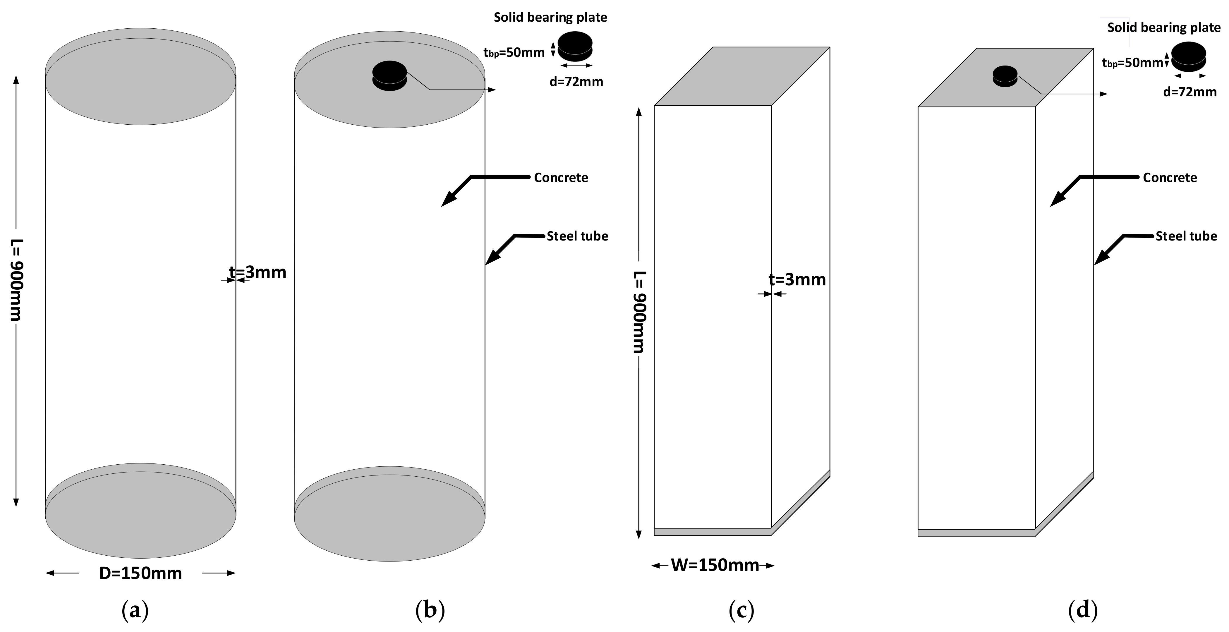
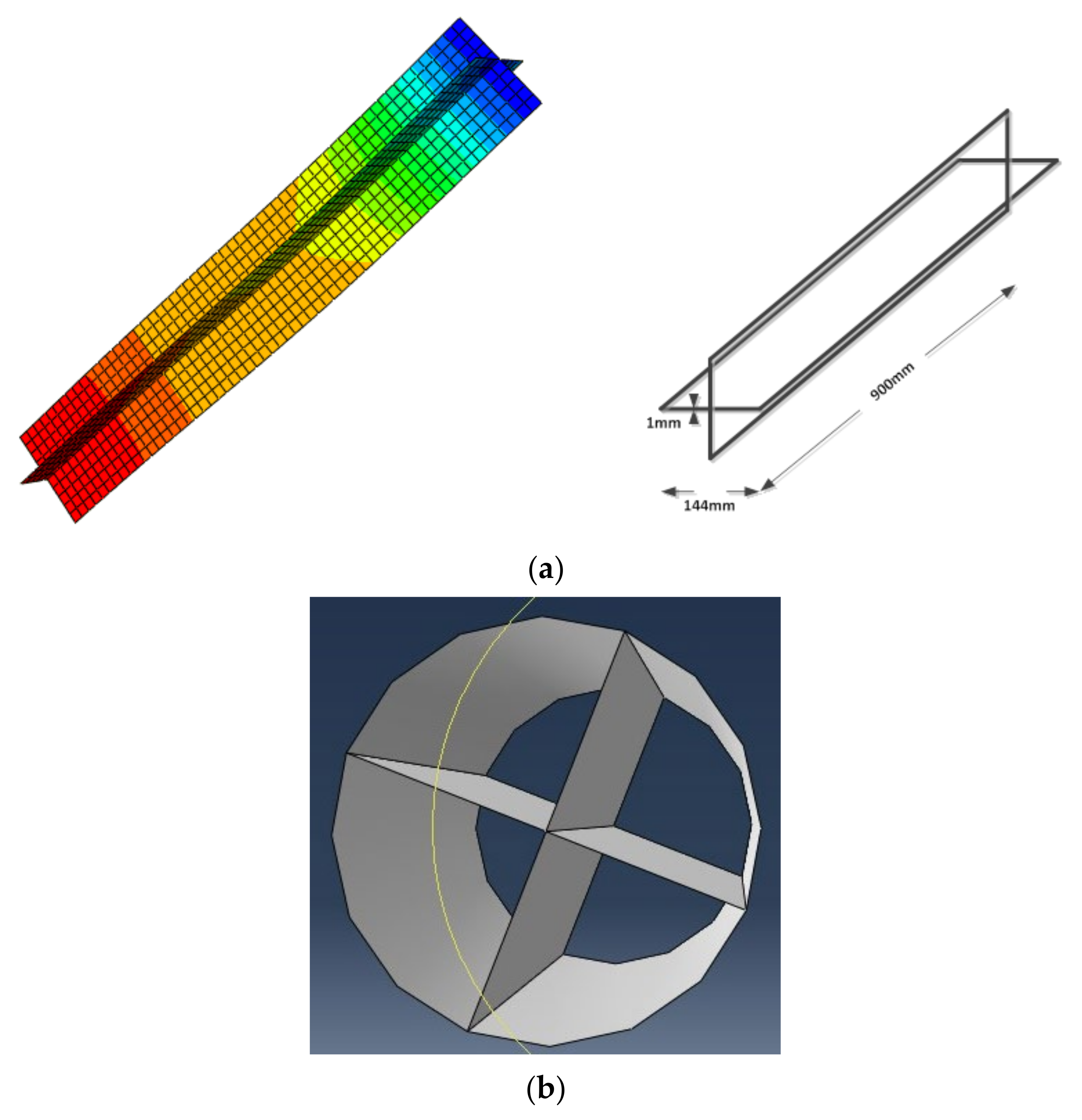
2.1. Models’ Geometry for the FEA

In the present study, CCFST and SCFST columns with the geometry indicated in Figure 1 were modelled and analysed in ABAQUS (version 6. 12) under full and partial axial loading. Under full compression, load was applied on the top endplate, while in partial loading condition, a solid bearing plate was designed to apply a compressive load that concentrated the load in the centres of the columns.
As is evident from the figure, the diameter (D) or width (W) of both columns is 150 mm, with length of 900 mm and wall thickness of 3 mm. The top and bottom endplates have the dimensions of 150 × 12 mm. For the partial compression, there should be a cylindrical bearing plate with the diameter of 72 mm and the thickness of 50 mm for both CCFST and SCFST columns, which have to be modelled to simulate the partial loading conditions. In the modelling process, it was assumed that the bottom endplate had no movement in the x and y directions; however, an upward displacement of −0.03 mm was applied in the z direction to effectively simulate the loading condition. The material properties and the appropriate concrete specifications were assumed according to Table 1 and Table 2 and [24,25,26,27,28]. In addition, to validate the FE models in this study, initially, structural behaviour of CFST columns under both partial and full compression was compared with the experimental tests [25,26,28,29,30,31,32].

2.2. Simulation of the Interaction between the Steel Tube and the Concrete

In order to simulate the interacting behaviour between steel and concrete, the so-called gap element was used in ABAQUS. This is a tool that can simulate the slip between materials by considering the difference in distance of two designated nodes; however, moving one node to its neighbour node was restricted. Usually, concrete confinement causes the main normal stress in this gap element. Therefore, it would be possible to model the confinement more feasibly. The shear stress, however, was simulated using a friction coefficient assigned to the gap element. This stress usually transfers between the infilled-concrete and the steel tube [33,34,35,36,37,38,39]. In this study, however, the option of “allow separation after contact” was activated, and the contacts between the concrete and the steel tube, the concrete and the end plate, and the steel tube and the end plate were simulated. In addition, the solid element with eight nodes was applied to model the concrete and the end plates, and the shell element with four nodes was picked up to model the steel tube.

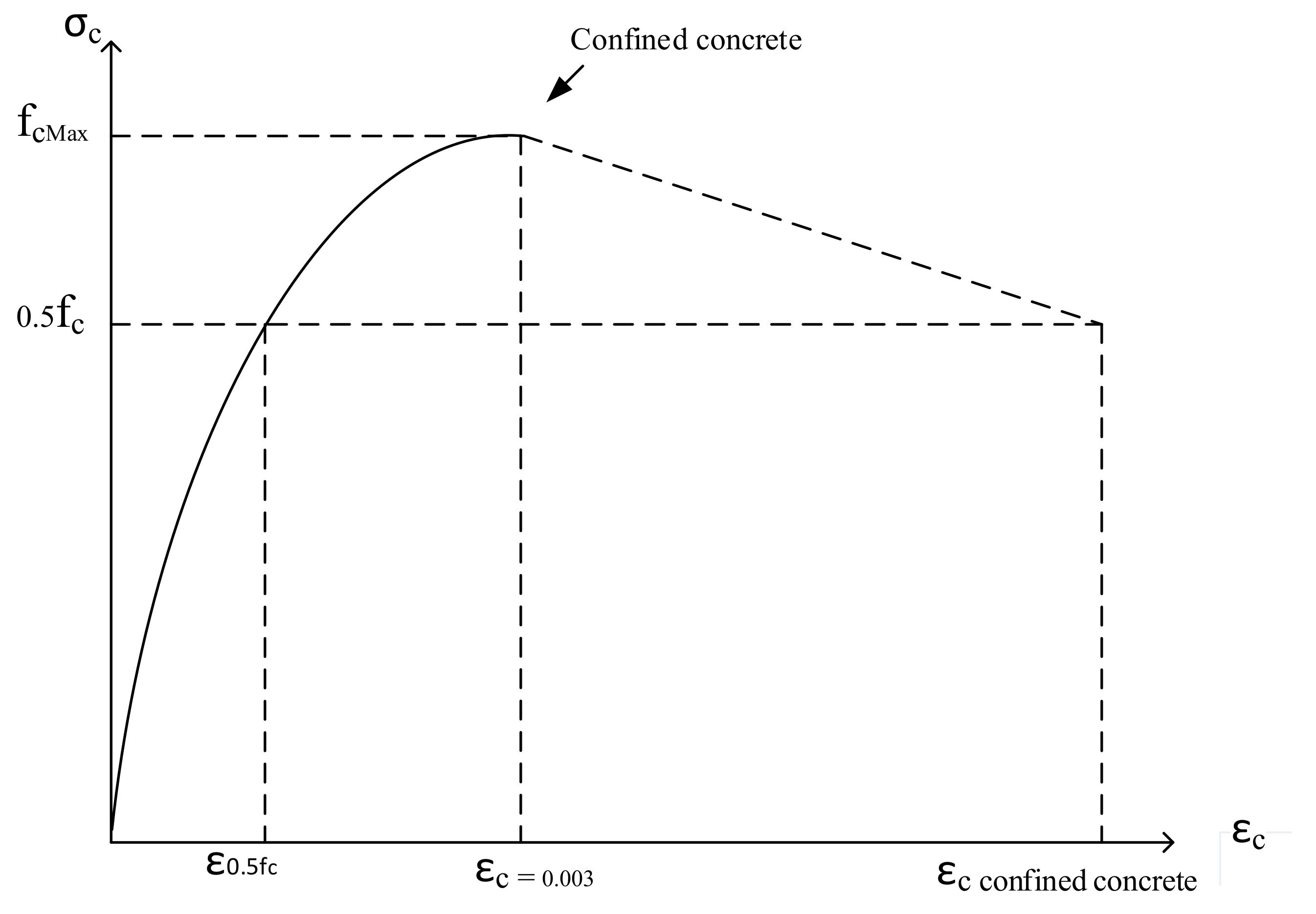
2.3. Material Properties

In FEA, it is important to assign appropriate material properties to each element, as they perform structurally according to their material properties. Concrete is a material that has different structural performance in compression and tension. The concrete’s tensile strength is typically 8% to 15% of its compressive strength [40]. The material properties of concrete applied in this research are indicated in Table 1. In this case study, self-consolidated concrete (SCC), as a high-strength concrete, was used; therefore, the mean compressive strength of the concrete was considered to be 52.6 MPa in the analysis [41,42,43].

2.4. Nonlinear Configuration for FEA

For the plastic behaviour of concrete, the concrete damage plasticity model was considered, and its specifications were assumed accordingly. The compressive stress–strain, however, was assumed linearly up to the point of 0.5fc (fc is the concrete compressive strength). In addition, it was considered that the maximum of fc can be reached if the corresponding compressive strain reaches 0.003, as indicated in Figure 2 (reproduced from [44]). The concrete elastic modulus, Ec, was obtained through the relationship 4700 (fc) 0.5 MPa [44,45,46,47]. The tensile response of the concrete is modelled as follows: at first, it was assumed that there is a linear correlation between the tensile stress and the concrete’s tensile strength, in which the maximum of this value is about 0.09 fc; after hitting this point, it goes down to zero, where the strain is approximately 10 times the strain of concrete’s ultimate tensile strength, εct; finally, the concrete’s dilation angle, ψ, as one of the important parameters in modelling concrete, displays the point where the plastic behaviour of concrete starts. Considering the evidence from the previous studies, this angle was assumed as 20° [39,40]. The damage plasticity model allows for introducing the appropriate tensile performance for the model. The other factors, such as dilation angle (ψ), eccentricity (e), the ratio of biaxial compression strength to uniaxial compression strength (fb0/fc0), the ratio of second stress invariant to the compressive meridian (K), and the viscosity parameter, that were assumed for the FEA are indicated in Table 2. Furthermore, in order to model the steel tube and its reinforcing element, it was assumed that stress–strain is linear and it follows the regulation of the isotropic hardening plasticity. The steel’s elastic modulus, Es, was assumed to be 206,000 MPa, while 0.281 was considered for the Poisson’s ratio, υs. In addition, it was assumed that the steel plasticity behaviour has to be ended when its strain, εs, touched about ten times the steel’s yield strain (10εsy) and/or stress reached to the maximum steel’s strength, fu. This is normally when the ultimate strain of steel, εsu, is equal to 0.1. The stress–strain curves achieved from the previous CFST experimental analysis were considered for validation purpose of the models in this study [47,48,49,50,51,52].

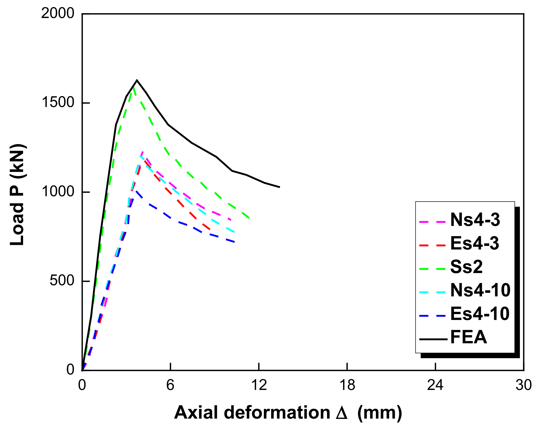
2.5. FEA for the Verification Purpose

In experimental analyses that were performed by Yang and Han and their team [25,31,32,48], the maximum load-bearing capacity of the CCFST column reached 1489 kN, whereas in the FE iterative solution, this value hit 1487 kN. However, in the post-buckling analysis, the column reached the maximum load-bearing capacity earlier than in the iterative solution analysis. The maximum load in the post-buckling method was 1424.40 kN, which is about 3.5% lower than the experimental value; however, in the Riks analysis, the maximum load-bearing capacity of the column was 1441.30 kN. The aforementioned results are also indicated in Table 3. They were also compared with the results of other studies that performed similar analyses of CFST columns, and they were in good agreement with the obtained outcomes of this study [29,30,31,32]. Therefore, in this research, the iterative solution, which is based on the modified Newton–Raphson method, was chosen for the nonlinear analysis of both types of columns, CCFST and SCFST.
To verify the FE models, they were simulated in ABAQUS according to the experimental studies [25,31,32,48]. As is evident from Figure 3, in this study, the main failure mode of the CCFST columns was outward buckling, and for the SCFST columns, it was the local buckling and concrete crushing. In this study, according to the ABAQUS reference manual, two major elements are applied. The elements are utilized in this model are shell element and solid elements. The 8-node solid element (C3D8R) was used to model the concrete and end plates; however, the 4-node shell element (S4R) was used to model the steel tube.
Due to the variety of parameters in this case study, a typical mesh could not be selected for all CFST columns; however, for each of them a mesh study was applied as the first step. To show how this process took place, a sample analysis for one of the columns was performed, and the results are indicated in Table 4. After assembling all materials and connections, to obtain an appropriate mesh for the analysis, convergence tests were performed to reach the optimum mesh size. For this purpose, different sizes were studied, and the related load-displacement curves were derived. After several trial-and-errors, we reached an optimum point where changing mesh size made almost no difference to the results. In this case, all the elements were meshed using a unique type and size that were suitable for this model. The mesh size, which was 15 mm, was taken as an appropriate mesh for our models as indicated in Table 4. The coarse mesh of 16 mm, 16.5 mm and 17 mm showed large differences compared with the data, while the finer mesh from 15.5 mm to 14.5 mm showed only very slight differences in the analysis; thus, based on the results, we chose the 15 mm mesh for our analysis.
After obtaining the optimum mesh-size, columns were modelled and the loading was applied on a bearing plate for both CCFST and SCFST columns. In order to simulate the loading conditions according to the experimental tests [46,47,48,49,53,54,55,56], the displacement was applied to the bottom of the columns. The results showed a good match between the FE outcomes and the actual results from the main reference tests (Cc2 and Ss2), as shown in Figs. 4 and 5. However, to ensure the right performance of the FEA, the trend of its curvature is also compared with some other studies [46,47,48,49,56,57,58,59,60]. The designated curves with labels NcI3, EcI3, NcI9, and EcI9 in Figure 4 are those where the FEA curvature’s trend is compared with the experimental one for the CCFST columns, whereas for the curves with labels Ns4-3, Es4-3, Ns4-10, and Es4-10 the numerical curvature is compared to the experimental one for the SCFST columns. The material properties, cross-section, slenderness, and some other specifications of the reference curvatures may differ from the main references of this study (Cc2 and Ss2), but their performance shows that the FEA results are in line with the studies of Yang and Han and their team [25,31,32,48] in this regard. As it is evident from Figure 4 and Figure 5, in the numerical analysis, the curves hit the maximum peak and buckled afterwards and experienced failure which these phenomena are in accordance with the results of other studies with similar conditions [46,47,48,49,50,51,52,53,54,55,56,57,58,59,60]. In the experimental analysis [49], the load-bearing capacity of the CCFST column was reached to 1489 kN, while in the FE analysis, it reached 1487 kN. For the SCFST column under fully compression, these values were 1599 kN for the experimental analysis and 1660 kN for the FEA. As it could be inferred, the maximum difference of the ultimate load-bearing capacity between the FEA and the experimental results is not wide, and therefore, the results from both partially and fully loading analysis are in acceptance with the empirical results. In the next step, a cross-shaped pate with the length of 900 mm and the width of 144 mm was used to improve ultimate load-bearing capacity of the column.

3. Analysis and Discussion

3.1. The CFST Columns Reinforced with a Cross-Shaped Plate

Having accomplished the verification process, a cross-shaped plate, as indicated in Figure 6, was symmetrically fitted in the middle of both CCFST and SCFST columns along with the length of the columns. The length of the cross-shaped plate was chosen equal to the column’s length, which is 900 mm. The width of the plate was 144 mm, and its thickness varied from 1 mm to 4 mm in order to study the effects of the cross-shaped plate’s thickness on the structural performance of the CFST columns. The boundary and loading conditions applied for this model are the same as the verified models. The reference point was pinned, which means the displacement assumed zero but free rotation (U1 = U2 = U3 = 0). In addition, for the bottom end plate, it was assumed that no movement in x and y direction (U1 = U2 = 0); however, according to Yang and Han [25] and other references [26,27,28,29], in the z direction, an upward displacement of −0.03 m was also applied to simulate the loading condition.
Figure 7 and Figure 8 show the contours of deflection for the models with cross-shaped plate with thickness from 1 mm to 4 mm. As is evident from the figures, the trend of the deflection is almost identical for all of the models, and the stress distribution along the columns is in accordance with the loading conditions.
In addition, as indicated in Figure 9, the thickness of the cross-shaped plate directly affected the ultimate load-bearing capacity of CCFST columns and improved their structural performance. The ultimate load-bearing capacity of each sample and its corresponding lateral deflection are summarised in Table 5. By comparing the results of Table 5 with the model without the cross-shaped plate, it could be understood that the ultimate load-bearing capacity of the FE model without the cross-shaped plate was 1487 kN. On the other hand, for the model with 1 mm plate, the ultimate load-bearing capacity was 1560.46 kN, while for the model with 4 mm plate, it was 1849.07 kN, therefore this shows an increase of approximately 25% of the ultimate strength compared to the models without the cross-shaped plate. Furthermore, as it is evident from Figure 9, the thickness of the stiffener greatly influenced the ultimate load of the SCFST columns and improved their structural integrity in terms of maximum bearing capacity, since the ultimate load changed from 1660 kN in the without stiffener case to 1810.50 kN with 1 mm stiffener and 2134.75 kN with 4 mm stiffener. The results of the ultimate load for each sample and their corresponding lateral deflections are summarized in Table 6.
Furthermore, the corresponding lateral deflection of the CCFST model without the cross-shaped plate was about 0.65 mm and this value for the model with 1 mm cross-shaped plate was around 0.27 mm. In addition, by increasing the thickness, the ultimate load-bearing capacity of the CCFST columns was increased and the corresponding lateral deflection was decreased accordingly. The mentioned improvements in the structural performance of the CCFST columns could be due to a better interaction between the steel tube and the concrete, which was led to decreasing of the lateral deflection and increasing of the ultimate load-bearing capacity of the column. The similar scenario was also true for the SCFST columns as the corresponding lateral defection decreased from 0.84 mm for the model without the cross-shaped plate to 0.43 mm for the model with 1 mm cross-shaped plate. However, for this type of CFST columns, by increasing the thickness of the cross-shaped plate, the lateral deflection was increased. This is probably because the SCFST columns did not perform homogeneously under compression after increasing the thickness of the cross-shaped plate.
Figure 10 illustrates the axial load (P) versus axial deformation (Δ) of the CCFST and SCFST columns with 1 mm, 2 mm, 3 mm and 4 mm cross-shaped plates. As it is evident from this figure, by reinforcing the CFST column using the cross-shaped plate, the peak value of the curves was raised up which means the ultimate load-bearing capacity of the CCFST column was increased, while the axial deformation value remained almost constant for all of the CCFST models. This trend is also inferred from Figure 10 for the SCFST columns with 1 mm, 2 mm, 3 mm and 4 mm cross-shaped plates; however, due to a nonhomogeneous stress sustained by the columns, their axial deformation was also increased.

3.2. The CFST Columns Reinforced with the Cross-Shaped Plate with an Opening

In this section, to improve the interacting performance of the steel tube and the concrete as well as enhancing the ultimate load-bearing capacity of the columns [61,62,63,64,65,66,67,68], an opening with the dimensions of 25 × 50 mm was inserted in the middle of the cross-shaped plate. The opening is in the middle of the plate, which has a length of 900 mm and a width of 144 mm. Afterwards, the CFST columns were re-analysed using the cross-shaped plate with the opening to observe the structural performance of the CFST columns. Figure 11 indicates the contour of deflection of the CCFST and SCFST columns with 1 mm cross-shaped plate comprising an opening in the middle.
In addition, as it is evident from Figure 12, by inserting the opening on the cross-shaped plate, the ultimate load-bearing capacity of the CCFST column was increased. According to the curve and the analysis data, the axial load was reached to the maximum of 1657 kN, which was approximately 6% higher compared to the ultimate load-bearing capacity of the CCFST column without opening [69,70,71,72].
On the other hand, the corresponding deflection of the model with the opening was 0.23 mm, while for the model without opening was 0.27 mm, which shows a decrease of approximately 17% of the lateral deflection of the column. The analysis was also performed for the CCFST models with 2 mm cross-shaped plate with opening, 3 mm cross-shaped plate with opening, and 4 mm cross-shaped plate with opening. The results are summarised in Table 7. Furthermore, Figure 12 shows the axial load versus lateral deflection for the SCFST models with different thickness of the cross-shaped plate with opening. The ultimate axial load for the stiffener with 1 mm thickness with opening was around 1792 kN with the corresponding lateral deflection of 0.45 mm, while load and deflection for the model with 2 mm cross-shaped plate and opening were 1889 kN and 0.46 mm, respectively. Therefore, although there was an increase in the ultimate bearing capacity of the SCFST columns by changing the thickness of the cross-shaped plate with opening, there was an overall decrease of the bearing capacity by using the opening on the cross-shaped plate in comparison to the models without it. In addition, the corresponding lateral deflection was also increased at each level. This shows that, despite of increasing of the ultimate bearing capacity of the CCFST columns by using the cross-shaped plate and the cross-shaped plate with opening, in the SCFST columns, using the cross-shaped plate with and without the opening does not necessarily improve the structural performance of the column. Table 7 indicates the summary and the comparison of the results of the FE analysis for both CCFST and SCFST columns.
Therefore, by inserting the opening on the cross-shaped plate with various thicknesses, the ultimate load-bearing capacity of the CCFST columns at each level was improved. This is mostly due to the increasing of the grip between the steel tube, the cross-shaped plate and concrete. This increment was finally increased by around 25% for the model with 4 mm cross-shaped plate and opening in comparison with the model with 1 mm cross-shaped plate without opening. In addition, using the cross-shaped plate and opening also positively affected the corresponding lateral deflection of the CCFST models. For the SCFST columns, in increasing the thickness of the cross-shaped plate from 1 mm to 4 mm, the maximum axial load also increased; however, the corresponding lateral deflection was decreased at first for the 1 mm plate, although afterwards, it changed upwards by increasing the thickness of the plate. In addition, using the cross-shaped plate with opening negatively influenced the structural performance of the SCFST columns and decreased the corresponding ultimate load-bearing capacity at each level and increased the deflection. This probably was due to the distributing of nonuniform stress along the columns that resulted from using the cross-shaped plate with the greater thickness imposing additional stress on the columns.
Figure 13 indicates the axial load (P) versus axial deformation (Δ) of the CCFST columns with different cross-shaped plates embracing the opening. As is evident from this figure, by making the opening on the cross-shaped plate, the peak value of the curves was increased for the CCFST columns. This means that the ultimate load-bearing capacity of these columns was increased, while the axial deformation value remained almost constant for all the models. The SCFST columns, however, experienced a decline in load-bearing capacity. This is due to a nonhomogeneous stress developed in the columns.
In addition, in order to revalidate the results of the FEA, the load-bearing capacity was also compared with the equations given by Eurocode 4 (EC4) and the American Concrete Institute (ACI), as well as with the modified equations proposed by Goode for EC4 and by Giakoumelis and Lam for ACI [55,67]. The outcomes of the FEA indicated good correlations with the theoretical results, as summarized in Table 8. For the CCFST columns, the EC4 to FEA average is 0.888, while the ACI to FEA average is 0.860. Using the modified ACI and EC4 equations, these averages are 1.034 and 0.859, respectively. The standard deviations in sequence are 0.028, 0.030, 0.033, and 0.027, which give the coefficients of variation of 3. 168%, 3. 464%, 3.151%, and 3.096%, respectively. In addition, for the SCFST columns, the EC4 to FEA average is 0.971, while the ACI to FEA one provides 0.894. For the modified ACI and EC4 equations, these averages are 0.878 and 0.937, respectively. The standard deviations in sequence are 0.014, 0.014, 0.020, and 0.014, which give the coefficients of variation of 1. 491%, 1.536%, 2.327%, and 1.519%, respectively. The comparison of these results reveals a good agreement between the FEA results and the theoretical ones. In addition, Figure 14 shows a comparison between the FEA results and the codes ones for both CCFST and the SCFST columns. It was revealed that for the CCFST columns, the equation from ACI code led to the results closest to the FEA by a difference equal to or less than 6%; however, for the SCFST columns, the equation from EC4 resulted in a similar condition.
For future studies, it is suggested to use perforated ribs with more openings instead of the cross-shaped plate with one opening for both CCFST and SCFST columns to evaluate their structural performance under axial compression. In addition, using fibre-reinforced polymer sheets may also improve the structural integrity of the mentioned CFST columns.

4. Conclusions

This study presented FEA using an iterative solution technique for CCFST and SCFST columns with diameter (width) of 150 mm and length of 900 mm that were reinforced with a cross-shaped plate with different thickness from 1 mm to 4 mm. Afterwards, an opening was inserted in the middle of each cross-shaped plate, and the CFST models were re-analysed to observe the effects of the opening on the ultimate load-bearing capacity of the columns and their lateral deflections. The results of this study were outlined as following:
-
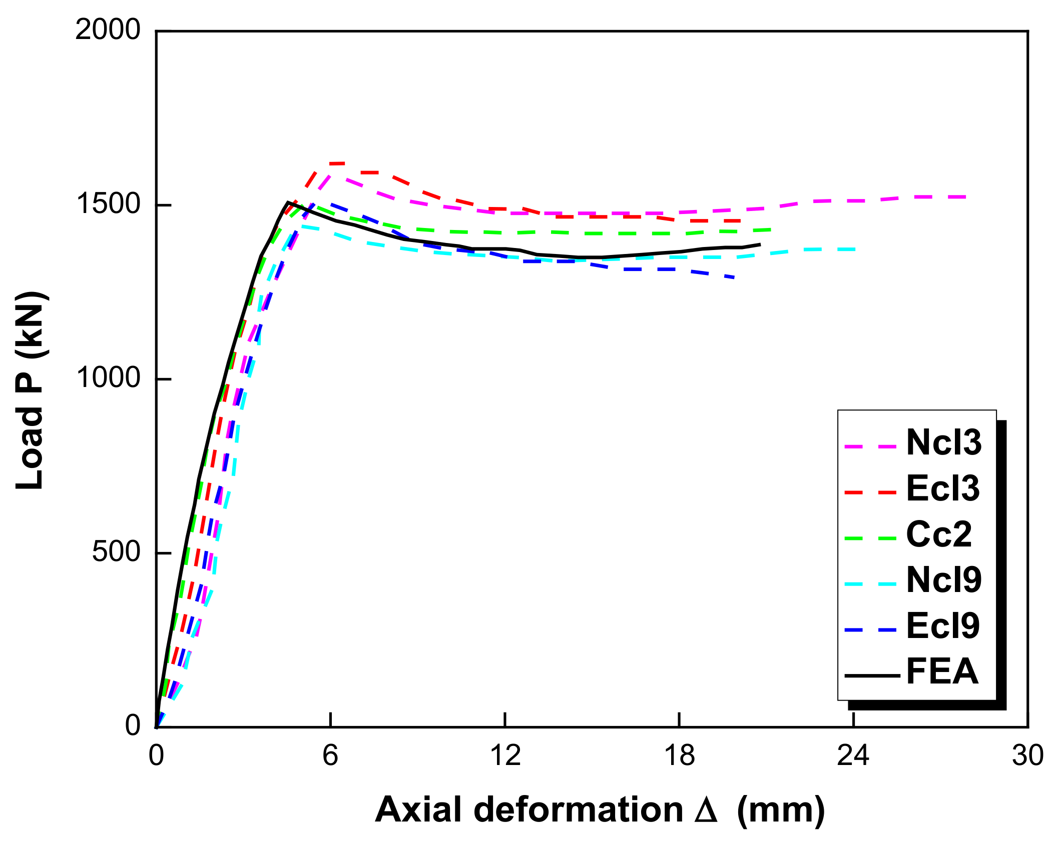
By means of finite element analysis, the CFST columns were numerically analysed using various nonlinear numerical methods, including the iterative solution, post buckling solution, and the Riks method. According to the analysis, the iterative solution technique showed better verification results when it was compared to the experimental results. Therefore, this approach was chosen for the further analyses.
-
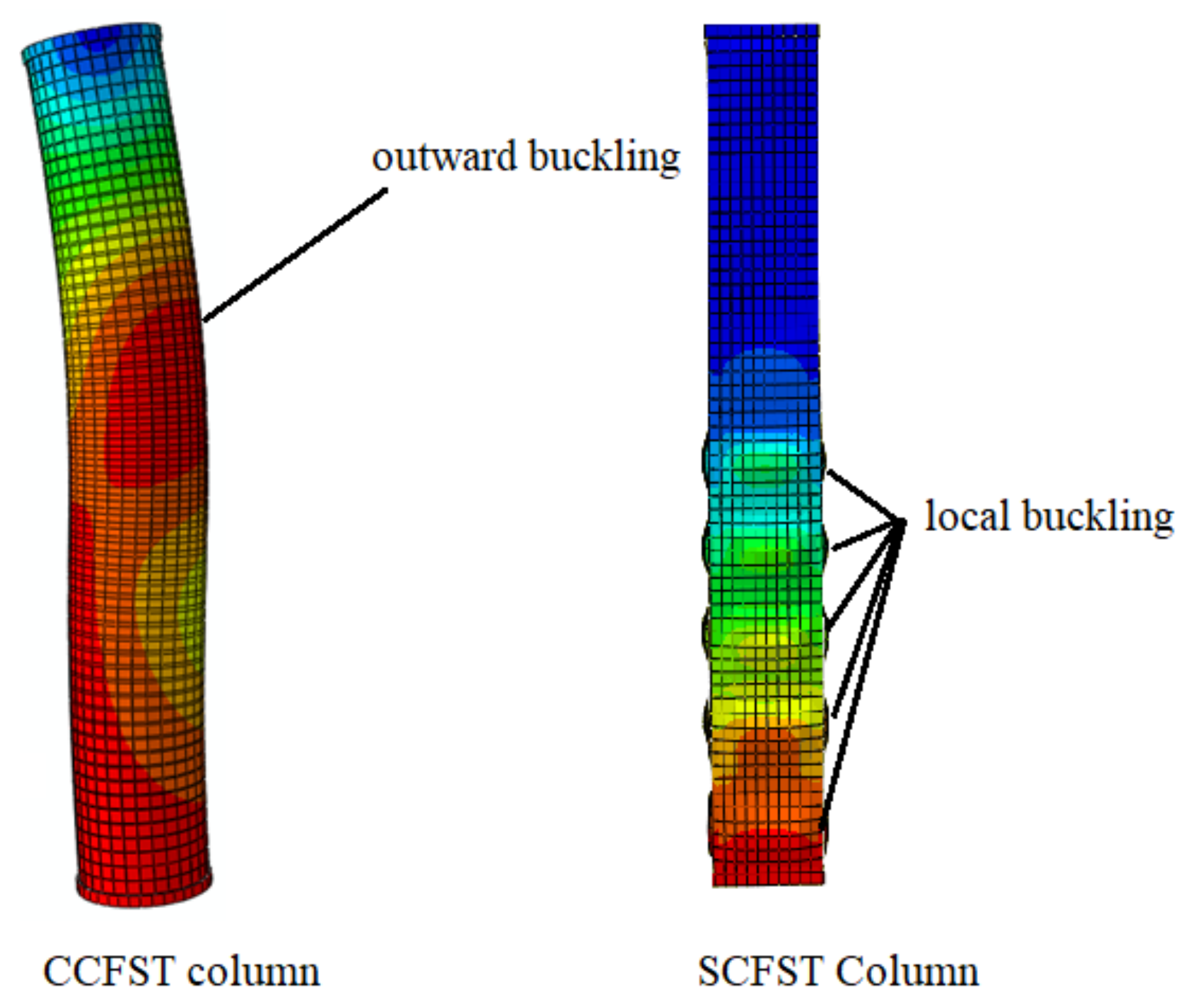
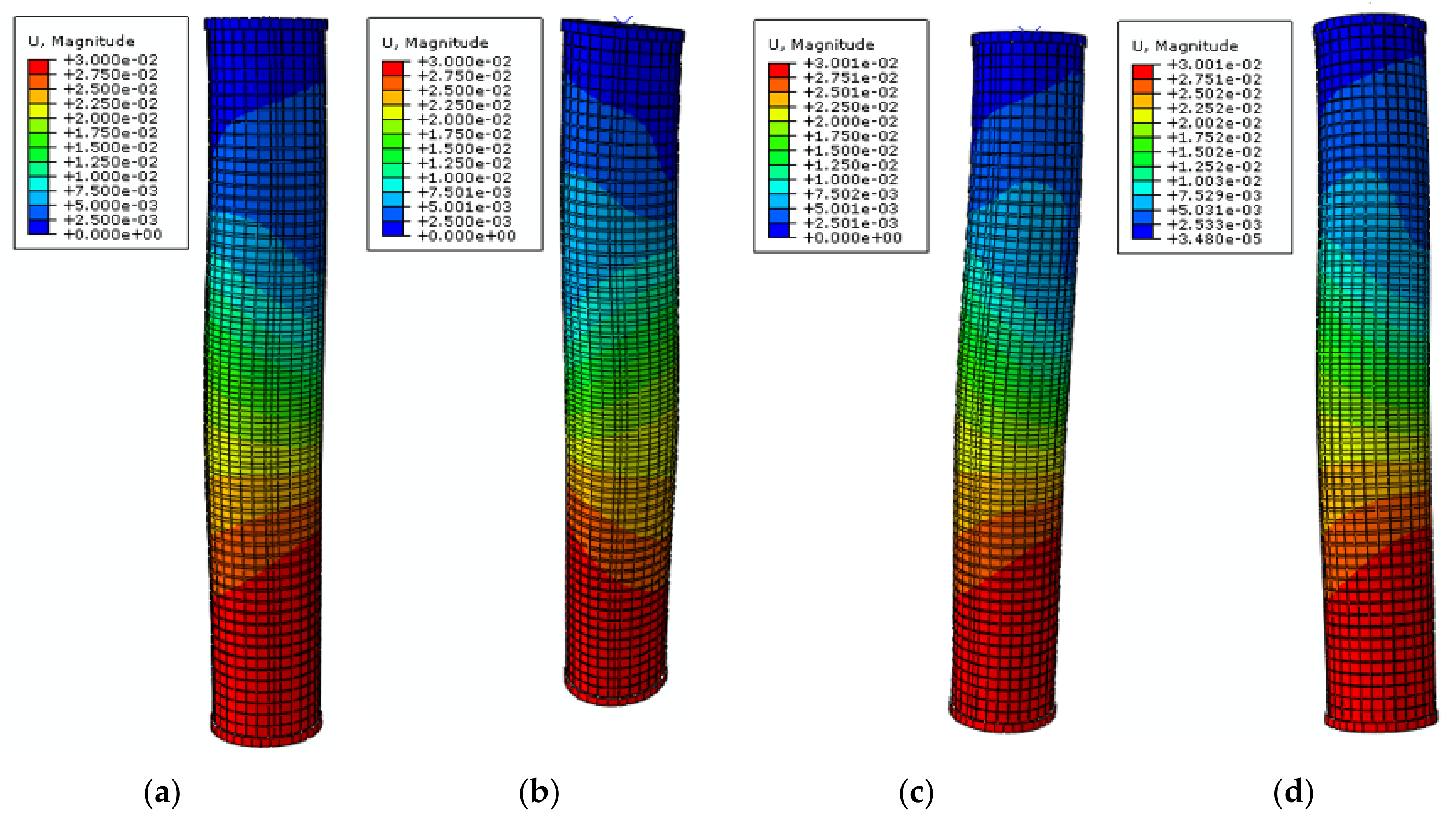
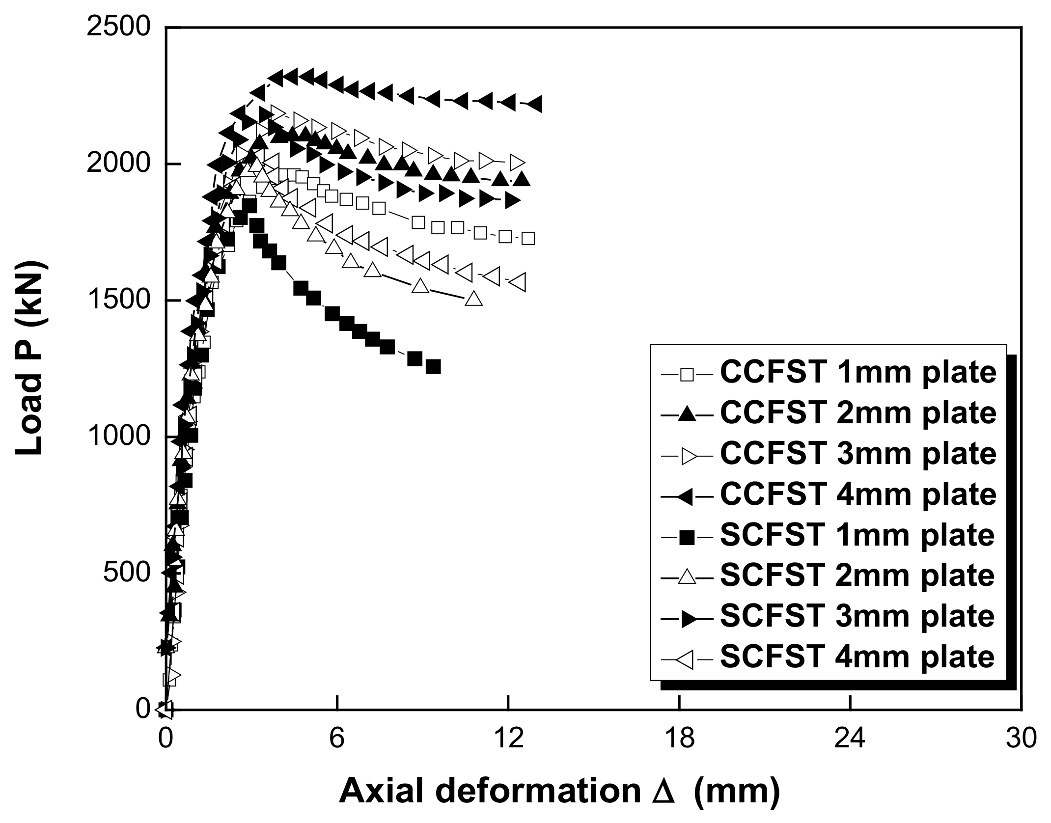
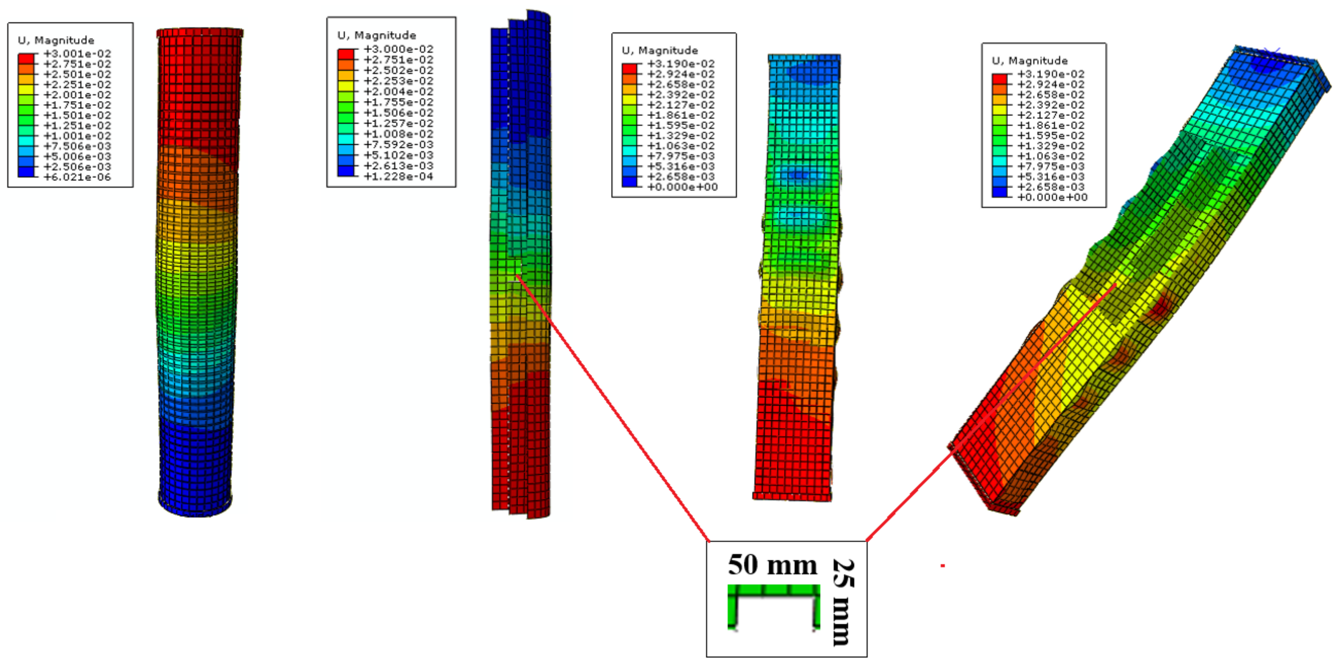
The CCFST columns reinforced with the cross-shaped plate showed better structural performances in terms of higher ultimate load-bearing capacity and lower lateral deflection compared to those of the columns without the cross-shaped plate. However, although the ultimate load-bearing capacity was also increased for the SCFST columns by adding the stiffener, the structural performance of these columns was changed drastically. In the models without the stiffener, there was almost no evidence of outward buckling and mostly inward buckling was observed, while for all four reinforced models with the cross-shaped stiffeners and various thickness, a local outward buckling was evident, which illustrates a significant change in structural performance of these columns with the reinforcement.
-
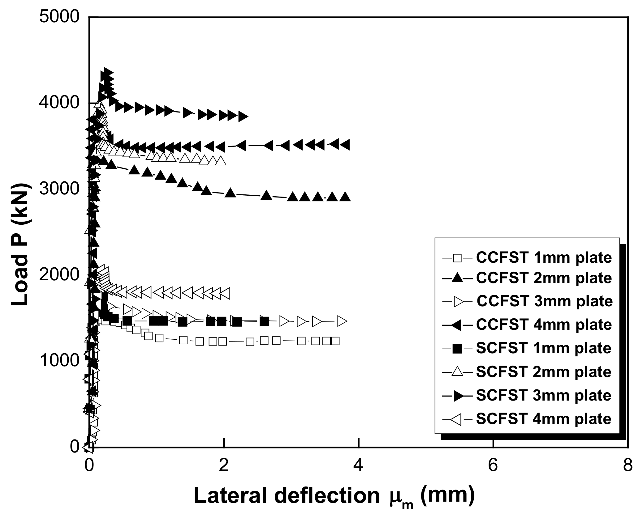
By increasing the thickness of the cross-shaped plate from 1 mm to 4 mm, the ultimate load-bearing capacity of the CCFST column was increased from 1560.46 kN to 1849.07 kN, and the corresponding lateral deflection was decreased from 0.27 mm to 0.10 mm. This shows that the thickness of the cross-shaped plate can significantly improve the structural behaviour of the CCFST columns. This is also evident for the SCFST columns, in which inserting the stiffener inside the column resulted in increasing of the maximum load-bearing capacity from 1810.50 kN to 2134 kN.
-
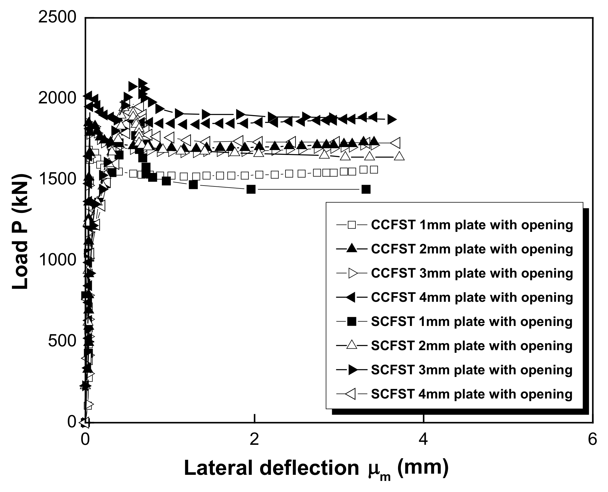
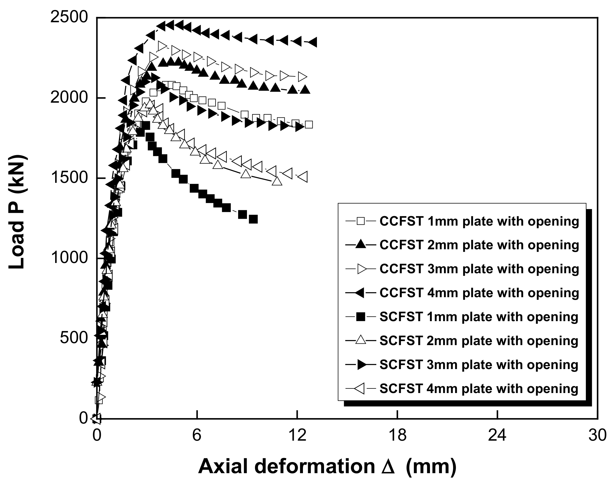
Furthermore, by inserting an opening on the cross-shaped plate, the ultimate load-bearing capacity of the CCFST column increased further. In fact, the axial load of the columns was increased from 1657 kN with 1 mm cross-shaped plate embracing the opening to 1967.32 kN with 4 mm cross-shaped plate and the opening. At the same time, the corresponding lateral deflection was decreased from 0.23 mm to 0.1 mm. However, for the SCFST columns, by inserting the opening on the stiffener, there was a decline in maximum bearing capacity of the columns when it was compared to the corresponding models without opening. Therefore, although there was an initial increase in the ultimate bearing capacity of the SCFST columns by changing the thickness of the cross-shaped plate with opening, an overall decrease of the bearing capacity was observed by using the opening on the cross-shaped plate in comparison to the SCFST models without it. In addition, the corresponding lateral deflection was also increased at each level.
-
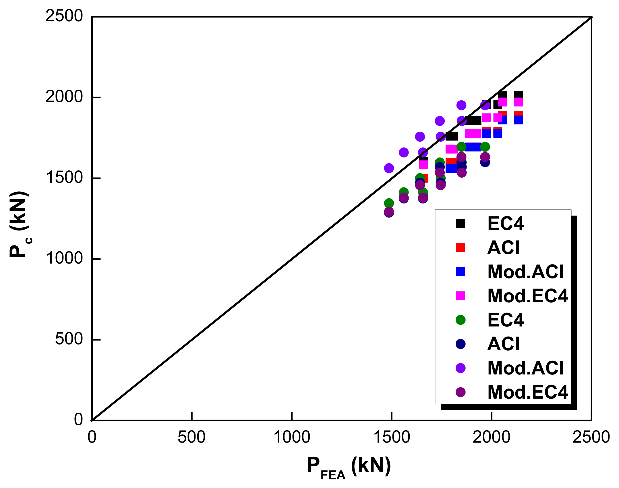
The results from FEA were compared with those derived from different equations (EC4, ACI, modified EC4, and modified ACI). It was revealed that for the circular CFST columns, the ACI code led to the results closest to FEA with a difference of 6%. For the square CFST instead, EC4 led to the best results, with a difference of 6% in comparison with FEA.

Author Contributions

Conceptualization, P.S., H.J. and P.G.A., methodology, P.S.; software, P.S.; validation, P.S., D.J.A., H.J. and P.G.A.; data curation, P.S.; writing—original draft preparation, P.S., H.J., P.G.A., D.J.A. and A.F., writing—review and editing, P.S., H.J., P.G.A., D.J.A. and A.F., supervision, H.J., P.G.A. and A.F. All authors have read and agreed to the published version of the manuscript.

Funding

This research was funded by National Natural Science Foundation of China, grant number 51978526.

Data Availability Statement

The data are available upon request.

Acknowledgments

The authors appreciate the library access and the facilities of Shanghai Jiao Tong University and Tongji University during this study. In addition, the financial support from NSFC under the grant number of 51978526 is highly appreciated.

Conflicts of Interest

The authors declare no conflict of interest.

References

  1. Demeijer, O.; Chen, J.J.; Li, M.G.; Wang, J.H. Influence of passively loaded piles on excavation-induced diaphragm wall displacements and ground settlements. Int. J. Geomech. 2018, 18, 04018052. [Google Scholar] [CrossRef]
  2. Chitawadagi, M.V.; Narasimhan, M.C.; Kulkarni, S.M. Axial strength of circular concrete-filled steel tube columns—DOE approach. J. Constr. Steel Res. 2010, 66, 1248–1260. [Google Scholar] [CrossRef]
  3. Shen, S.L.; Wang, Z.F.; Sun, W.J.; Wang, L.B.; Horpibulsuk, S. A field trial of horizontal jet grouting using the composite-pipe method in the soft deposits of Shanghai. Tunn. Undergr. Sp. Technol. 2013, 35, 142–151. [Google Scholar] [CrossRef]
  4. Han, L.H.; Li, W.; Bjorhovde, R. Developments and advanced applications of concrete-filled steel tubular (CFST) structures: Members. J. Constr. Steel Res. 2014, 100, 211–228. [Google Scholar] [CrossRef]
  5. Sarir, P.; Shen, S.L.; Arulrajah, A.; Horpibulsuk, S. Concrete wedge and coarse sand coating shear connection system in GFRP concrete composite deck. J. Constr. Build. Mater. 2016, 114, 650–655. [Google Scholar] [CrossRef]
  6. Halding, P.S. Reduction of the carbon footprint of precast columns by combining normal and light aggregate concrete. Buildings 2022, 12, 215. [Google Scholar] [CrossRef]
  7. Song, T.Y.; Han, L.H.; Yu, H.X. Concrete filled steel tube stub columns under combined temperature and loading. J. Constr. Steel Res. 2010, 66, 369–384. [Google Scholar] [CrossRef]
  8. Naik, T.R.; Kumar, R.; Ramme, B.W.; Canpolat, F. Development of high-strength, economical self-consolidating concrete. Constr. Build. Mater. 2012, 1, 463–469. [Google Scholar] [CrossRef]
  9. Roeder, C.W.; Lehman, D.E.; Bishop, E. Strength and stiffness of circular concrete-filled tubes. J. Struct. Eng. 2010, 136, 1545–1553. [Google Scholar] [CrossRef]
  10. Vrcelj, Z.; Uy, B. Strength of slender concrete-filled steel box columns incorporating local buckling. J. Constr. Steel Res. 2002, 58, 275–300. [Google Scholar] [CrossRef]
  11. Hossain, K.M. Axial load behaviour of thin walled composite columns. Compos. Part B Eng. 2003, 34, 715–725. [Google Scholar] [CrossRef]
  12. Zeghiche, J.; Chaoui, K. An experimental behaviour of concrete-filled steel tubular columns. J. Constr. Steel Res. 2005, 61, 53–66. [Google Scholar] [CrossRef]
  13. De Oliveira WL, A.; de Nardin, S.; de Cresce El Debs AL, H.; El Debs, M.K. Influence of concrete strength and length/diameter on the axial capacity of CFT columns. J. Constr. Steel Res. 2009, 65, 2103–2110. [Google Scholar] [CrossRef]
  14. Lyu, H.M.; Shen, S.L.; Zhou, A.N.; Yang, J. Perspectives for flood risk assessment and management for mega-city metro system. Tunn. Undergr. Sp. Technol. 2019, 84, 31–44. [Google Scholar] [CrossRef]
  15. Sarir, P.; Chen, J.; Asteris, P.G.; Armaghani, D.J.; Tahir, M.M. Developing GEP tree-based, neuro-swarm, and whale optimization models for evaluation of bearing capacity of concrete-filled steel tube columns. Eng. Comput. 2021, 37, 1–19. [Google Scholar] [CrossRef]
  16. Baig, M.N.; Fan, J.; Nie, J. Strength of concrete filled steel tubular columns. Tsinghua Sci. Technol. 2006, 11, 657–666. [Google Scholar] [CrossRef]
  17. Zhao, J.L.; Shen, S.L.; Wang, L.B.; Chen, J. Modification on FIP design model for interior anchorage zones of post-tensioned concrete structures. KSCE J. Civil Eng. 2011, 15, 487–495. [Google Scholar] [CrossRef]
  18. Shen, S.L.; Hou, D.W.; Zhao, J.L.; Horpibulsuk, S.; Yin, Z.Y. Assessment of internal forces for intermediate anchorage zone of post-tensioned concrete structure. Constr. Build. Mater. 2014, 64, 370–378. [Google Scholar] [CrossRef]
  19. Chen, C.C.; Ko, J.W.; Huang, G.L.; Chang, Y.M. Local buckling and concrete confinement of concrete-filled box columns under axial load. J. Constr. Steel Res. 2012, 43, 41–48. [Google Scholar] [CrossRef]
  20. Hu, H.S.; Liu, Y.; Zhuo, B.T.; Guo, Z.X.; Shahrooz, B.M. Axial compressive behaviour of square CFST Columns through direct measurement of load components. J. Struct. Eng. 2018, 144, 04018201. [Google Scholar] [CrossRef]
  21. Lai, Z.; Varma, A.H. Effective stress-strain relationships for analysis of noncompact and slender filled composite (CFT) members. Eng. Struct. 2016, 12, 457–472. [Google Scholar] [CrossRef]
  22. Liu, F.; Shen, S.L.; Hou, D.W.; Arulrajah, A.; Horpibulsuk, S. Enhancing behavior of large volume underground concrete structure using expansive agents. Constr. Build. Mater. 2016, 114, 49–55. [Google Scholar] [CrossRef]
  23. Thai, H.T.; Kim, S.E. Second-order inelastic analysis of cable-stayed bridges. Finite Elem. Anal. Des. 2012, 1, 48–55. [Google Scholar] [CrossRef]
  24. Ding, F.X.; Yu, Z.W.; Bai, Y.; Gong, Y.Z. Elasto-plastic analysis of circular concrete-filled steel tube stub columns. J. Constr. Steel Res. 2011, 67, 1567–1577. [Google Scholar] [CrossRef]
  25. Yang, Y.F.; Han, L.H. Concrete filled steel tube (CFST) columns subjected to concentrically partial compression. Thin-Walled Struct. 2012, 50, 147–156. [Google Scholar] [CrossRef]
  26. Qiu, F.; Li, W.; Pan, P.; Qian, J. Experimental tests on reinforced concrete columns under biaxial quasi-static loading. Eng. Struct. 2002, 24, 419–428. [Google Scholar] [CrossRef]
  27. Iacobucci, R.D.; Sheikh, S.; Bayrak, O. Retrofit of square concrete columns with carbon fiber-reinforced polymer for seismic resistance. ACI Struct. J. 2003, 100, 785–794. [Google Scholar]
  28. Choi, W.C.; Yun, H.D. Compressive behavior of reinforced concrete columns with recycled aggregate under uniaxial loading. Eng. Struct. 2012, 41, 285–293. [Google Scholar] [CrossRef]
  29. Kishen, J.C.; Kumar, A. Finite element analysis for fracture behavior of cracked beam-columns. Finite Elem. Anal. Des. 2004, 40, 1773–1789. [Google Scholar] [CrossRef]
  30. Mollazadeh, M.H. Load Introduction into Concrete-Filled Steel Tubular Columns. Ph.D. Thesis, School of Mechanical, Aerospace and Civil Engineering, The University of Manchester, Manchester, UK, 2015. [Google Scholar]
  31. Han, L.H.; Liu, W.; Yang, Y.F. Behaviour of concrete-filled steel tubular stub columns subjected to axially local compression. J. Constr. Steel Res. 2008, 64, 377–387. [Google Scholar] [CrossRef]
  32. Yang, Y.F.; Han, L.H.; Sun, B.H. Experimental behaviour of partially loaded concrete filled double-skin steel tube (CFDST) sections. J. Constr. Steel Res. 2012, 71, 63–73. [Google Scholar] [CrossRef]
  33. Gupta, P.K.; Singh, H. Numerical study of confinement in short concrete filled steel tube columns. Lat. Am. J. Solids Struct. 2014, 11, 1445–1462. [Google Scholar] [CrossRef] [Green Version]
  34. Huang, Y.; Xiao, J.Z.; Yang, Z.; Wang, Q. Behaviour of concrete filled-steel tubes under axial load. Proc. Inst. Civ. Eng.–Struct. Build. 2016, 169, 210–222. [Google Scholar] [CrossRef]
  35. Akbulut, H.; Gundogdu, O.; Şengül, M. Buckling behaviors of laminated composite stepped flat columns. Finite Elem. Anal. Des. 2010, 46, 1061–1067. [Google Scholar] [CrossRef]
  36. Su, J.; Wang, Y. Equivalent dynamic infinite element for soil–structure interaction. Finite Elem. Anal. Des. 2013, 63, 1–7. [Google Scholar] [CrossRef]
  37. Moon, J.; Roeder, C.W.; Lehman, D.E.; Lee, H.E. Analytical modeling of bending of circular concrete-filled steel tubes. Eng. Struct. 2012, 42, 349–361. [Google Scholar] [CrossRef]
  38. Moon, J.; Roeder, C.W.; Lehman, D.E.; Lee, H.E. Strength of circular concrete-filled tubes with and without internal reinforcement under combined loading. J. Struct. Eng. 2012, 139, 04013012. [Google Scholar] [CrossRef] [Green Version]
  39. Kazakov, K.S. Elasto dynamic infinite elements with united shape functions for soil–structure interaction. Finite Elem. Anal. Des. 2010, 46, 936–942. [Google Scholar] [CrossRef]
  40. Myers, K.J.J.; Bloch, E. Comparison of prestress losses for pedestrian bridges. constructed with high-strength concrete and high-strength self-consolidating concrete. J. Bridge Eng. 2013, 18, 871–878. [Google Scholar] [CrossRef]
  41. ACI Committee 441. 441R-96: High Strength Concrete Columns; ACI: Detroit, MI, USA, 2002. [Google Scholar]
  42. ACI Committee 318. Building Code Requirements for Structural Concrete (ACI 318-11M) and Commentary; ACI: Detroit, MI, USA, 2011. [Google Scholar]
  43. Genikomsou, A.S.; Polak, M.A. Finite element analysis of punching shear of concrete slabs using damaged plasticity model in ABAQUS. Eng. Struct. 2015, 98, 38–48. [Google Scholar] [CrossRef]
  44. Hu, H.T.; Huang, C.S.; Wu, M.H.; Wu, Y.M. Nonlinear analysis of axially loaded concrete-filled tube columns with confinement effect. J. Struct. Eng. 2003, 129, 1322–1329. [Google Scholar] [CrossRef] [Green Version]
  45. Sümer, Y.; Aktas, M. Defining parameters for concrete damage plasticity model. Chall. J. Struct. Mech. 2015, 1, 149–155. [Google Scholar]
  46. ACI Committee 363. 363R-10 Report on High-Strength Concrete; ACI: Detroit, MI, USA, 2010. [Google Scholar]
  47. David, H. ABAQUS 6.12 Standard User’s Manual; Dassault Systemes Simulia Corp.: Providence, RI, USA, 2012. [Google Scholar]
  48. Yang, Y.F.; Liu, M.; Bie, X. A research on the bearing capacity of four-legged CFST latticed members under axial compression. Prog. Steel Build. Struct. 2022, 24, 18–26. [Google Scholar]
  49. An, Y.F.; Han, L.H.; Zhao, X.L. Finite element analysis on concrete-encased CFST stub columns. In Proceedings of the 2013 World Congress on Advances in Structural Engineering and Mechanics (ASEM13), Jeju, Republic of Korea, 8–12 September 2013. [Google Scholar]
  50. Jayaganesh, S.; Raja, M.J.; Ganesh, P.G.; Jegan, J. Effects of concentrical partial (local) compression on the structural behavior of concrete filled steel tubular column. Adv. Mater. Sci. Eng. 2015, 2015, 491038. [Google Scholar] [CrossRef] [Green Version]
  51. Qu, X.; Chen, Z.; Sun, G. Axial behaviour of rectangular concrete-filled cold-formed steel tubular columns with different loading methods. Steel Compos. Struct. 2015, 18, 71–90. [Google Scholar] [CrossRef]
  52. Yadav, R.; Chen, B. Parametric study on the axial behaviour of concrete filled steel tube (CFST) columns. Am. J. Appl. Sci. Res. 2017, 3, 37–41. [Google Scholar] [CrossRef] [Green Version]
  53. Tao, Z.; Uy, B.; Han, L.H.; Wang, Z.B. Analysis and design of concrete-filled stiffened thin-walled steel tubular columns under axial compression. Thin-Walled Struct. 2009, 47, 1544–1556. [Google Scholar] [CrossRef]
  54. Patel, V.I.; Liang, Q.Q.; Hadi, M.N. Nonlinear analysis of axially loaded circular concrete-filled stainless steel tubular short columns. J. Constr. Steel Res. 2014, 101, 9–18. [Google Scholar] [CrossRef] [Green Version]
  55. Chu, K. Axial Load Behaviour of Steel Tube Columns In-Filled with Various High-Performance concrete. Master’s Thesis, Ryerson University, Toronto, ON, Canada, 2014. [Google Scholar]
  56. Reddy GS, R.; Bolla, M.; Patton, M.L.; Adak, D. Comparative study on structural behaviour of circular and square section-Concrete Filled Steel Tube (CFST) and Reinforced Cement Concrete (RCC) stub column. Structures 2021, 29, 2067–2081. [Google Scholar] [CrossRef]
  57. Liang, Q.Q.; Uy, B.; Bradford, M.A.; Ronagh, H.R. Strength analysis of steel & concrete composite beams in combined bending and shear. J. Struct. Eng. 2005, 131, 1593–1600. [Google Scholar]
  58. Li, J.; Hadi, M.N.S. Behaviour of externally confined high-strength concrete columns under eccentric loading. Composite Struct. 2003, 62, 145–153. [Google Scholar] [CrossRef]
  59. Yang, Y.; Han, L. Experiments on rectangular concrete-filled steel tubes loaded axially on a partially stressed cross-sectional area. J. Constr. Steel Res. 2009, 65, 1617–1630. [Google Scholar] [CrossRef]
  60. Yang, Y.; Han, L. Behaviour of concrete filled steel tubular (CFST) stub columns under eccentric partial compression. Thin-Walled Struct. 2011, 49, 379–395. [Google Scholar] [CrossRef]
  61. Chen, J.; Shen, S.L.; Yin, Z.Y.; Horpibulsuk, S. Closed-form solution for shear lag with derived flange deformation function. J. Constr. Steel Res. 2014, 102, 104–110. [Google Scholar] [CrossRef]
  62. Cui, Q.L.; Xu, Y.S.; Shen, S.L.; Yin, Z.Y.; Horpibulsuk, S. Field performance of concrete pipes during jacking in cemented sandy silt. Tunn. Undergr. Sp. Technol. 2015, 49, 336–344. [Google Scholar] [CrossRef]
  63. Hou, D.W.; Zhao, J.L.; Shen, J.S.; Chen, J. Investigation and improvement of strut- and-tie model for design of end anchorage zone in post-tensioned concrete structure. Constr. Build. Mater. 2017, 13, 482–494. [Google Scholar] [CrossRef] [Green Version]
  64. Li, P.; Du, S.J.; Shen, S.L.; Wang, Y.H.; Zhao, H.H. Timoshenko beam solution for the response of existing tunnels because of tunneling underneath. Int. J. Numer. Anal. Methods Geomech. 2016, 40, 766–784. [Google Scholar] [CrossRef]
  65. Liao, S.M.; Peng, F.L.; Shen, S.L. Analysis of shearing effect on tunnel induced by load transfer along longitudinal direction. Tunn. Undergr. Sp. Technol. 2008, 23, 421–430. [Google Scholar] [CrossRef]
  66. Giakoumelis, G.; Lam, D. Axial capacity of circular concrete-filled tube columns. J. Constr. Steel Res. 2004, 60, 1049–1068. [Google Scholar] [CrossRef]
  67. ACI Committee 318. Building Code Requirements for Structural Concrete (ACI 318-95); American Concrete Institute: Detroit, MI, USA, 1995. [Google Scholar]
  68. Nguyen, T.T.; Thai, H.T.; Ngo, T.; Uy, B.; Li, D. Behaviour and design of high strength CFST columns with slender sections. J. Constr. Steel Res. 2021, 182, 106645. [Google Scholar] [CrossRef]
  69. Zeng, J.J.; Zheng, Y.W.; Liu, F.; Guo, Y.C.; Hou, C. Behavior of FRP Ring-Confined CFST columns under axial compression. Compos. Struct. 2021, 257, 113166. [Google Scholar] [CrossRef]
  70. Patel, V.I.; Hassanein, M.F.; Thai, H.T.; Al Abadi, H.; Elchalakani, M.; Bai, Y. Ultra-high strength circular short CFST columns: Axisymmetric analysis, behaviour and design. Eng. Struct. 2019, 179, 268–283. [Google Scholar] [CrossRef]
  71. Jiang, J.; Chen, S. Experimental and numerical study of double-through plate connections to CFST column. J. Constr. Steel Res. 2019, 153, 385–394. [Google Scholar] [CrossRef]
  72. Thomas, J.; Sandeep, T.N. Capacity of short circular CFST columns with inner vertical plates welded intermittently. J. Constr. Steel Res. 2020, 165, 105840. [Google Scholar] [CrossRef]
Figure 1. Cross-section of (a) CCFST under full compression, (b) CCFST under partial compression, (c) SCFST under full compression, (d) SCFST under partial compression.
Buildings 12 02071 g001
Figure 2. Typical stress–strain curves of unconfined and confined concrete.
Buildings 12 02071 g002
Figure 3. The main failure modes of CCFST and SCFST columns in this study.
Buildings 12 02071 g003
Figure 4. Axial load (P)—axial deformation (Δ) of the FEA and the experimental tests for the CCFST [45,46,47,48,55,56,57,58,59].
Buildings 12 02071 g004
Figure 5. Axial load (P)—axial deformation (Δ) of the FEA and the experimental tests for the SCFST [45,46,47,48,55,56,57,58,59].
Buildings 12 02071 g005
Figure 6. (a) The cross-shaped plate inserted in the CFST columns (b) The cross-section of the model in ABAQUS.
Buildings 12 02071 g006
Figure 7. Contour of deflection for the CCSFT column with (a) 1 mm, (b) 2 mm, (c) 3 mm, and (d) 4 mm cross-shaped plates.
Buildings 12 02071 g007
Figure 8. Contour of deflection for the SCSFT column with (a) 1 mm, (b) 2 mm, (c) 3 mm, and (d) 4 mm cross-shaped plates.
Buildings 12 02071 g008
Figure 9. Axial load (P)-lateral deflection (um) of the CCFST and SCFST models with different cross-shaped plates.
Buildings 12 02071 g009
Figure 10. Axial load (P)-axial deformation (Δ) of the CCFST and SCFST models with different cross-shaped plates.
Buildings 12 02071 g010
Figure 11. The contour of deflection of CCFST and SCFST columns having 1 mm cross-shaped plate with opening.
Buildings 12 02071 g011
Figure 12. Axial load (P)-lateral deflection (um) of CCFST and SCFST models with different cross-shaped plates provided with opening.
Buildings 12 02071 g012
Figure 13. Axial load (P)-axial deformation (Δ) of CCFST and SCFST models different cross-shaped plates with opening.
Buildings 12 02071 g013
Figure 14. Comparison between results of FEA and codes.
Buildings 12 02071 g014
Table 1. Summary of the material properties considered in FEA.
PropertiesSteelHigh-Strength Concrete
Young’s Modulus (MPa)206,00033,800
Poisson’s Ratio0.2810.2
Mass Density (Kg/m3)78002300
Compressive Strength (MPa)-52.6
Initial Yield Stress (MPa)324.4-
Tensile Strength466.51.5
Table 2. Parameters for concrete damage plasticity behaviour of concrete.
PropertiesValue
Dilation Angle (ψ)20°
Eccentricity0.2
fb0/fc01.1
K0.7
Viscosity0.001
Table 3. Maximum load-bearing capacities for different FE solutions.
DescriptionUltimate Load-Bearing Capacity (kN)
Experimental analysis1478.00
FE-Iterative solution1487.00
FE-Post buckling method1424.40
FE-Riks method1441.30
Table 4. Parameters for mesh study.
Mesh TypeMesh SizeNumber of Elements Number of NodesPeak of Loading
C3D8R-S4R14.5 mm832399971487.03 kN
C3D8R-S4R15 mm806496121487.01 kN
C3D8R-S4R15.5 mm775492151475.67 kN
C3D8R-S4R16 mm745388191453.54 kN
C3D8R-S4R16.5 mm712184231452.98 kN
C3D8R-S4R17 mm675680251452.60 kN
Table 5. Summary of ultimate load-bearing capacity and lateral deflection of the FE models of CCFST with different thickness of the cross-shaped plate.
DescriptionUltimate Load (kN)Lateral Deflection (mm)
FE model with 1 mm cross-shaped plate1560.460.27
FE model with 2 mm cross-shaped plate1641.960.20
FE model with 3 mm cross-shaped plate1740.690.12
FE model with 4 mm cross-shaped plate1849.070.10
Table 6. Summary of ultimate load-bearing capacity and lateral deflection of the FE models of SCFST with different thickness of the cross-shaped plate.
DescriptionUltimate Load (kN)Lateral Deflection (mm)
FE model with 1 mm cross-shaped plate1810.500.43
FE model with 2 mm cross-shaped plate1927.000.46
FE model with 3 mm cross-shaped plate2031.100.48
FE model with 4 mm cross-shaped plate2134.750.49
Table 7. Summary and comparison of the FEA results.
DescriptionMax. Load Baring Capacity (kN)Lateral Deflection (mm)
CCFST without the cross-shape plate1487.000.65
CCFST with 1 mm cross-shape plate1560.460.27
CCFST with 1 mm cross-shape plate with opening1657.000.23
CCFST with 2 mm cross-shape plate1641.960.20
CCFST with 2 mm cross-shape plate with opening1745.480.17
CCFST with 3 mm cross-shape plate1740.690.12
CCFST with 3 mm cross-shape plate with opening1851.050.11
CCFST with 4 mm cross-shape plate1849.070.10
CCFST with 4 mm cross-shape plate with opening1967.320.10
SCFST without the cross-shape plate1660.000.84
SCFST with 1 mm cross-shape plate1810.500.43
SCFST with 1 mm cross-shape plate with opening1792.000.45
SCFST with 2 mm cross-shape plate1927.000.46
SCFST with 2 mm cross-shape plate with opening1889.000.46
SCFST with 3 mm cross-shape plate2031.100.48
SCFST with 3 mm cross-shape plate with opening1974.000.50
SCFST with 4 mm cross-shape plate2134.700.49
SCFST with 4 mm cross-shape plate with opening2055.000.51
Table 8. Comparison of analysis results.
DescriptionLoad Baring Capacity (kN)
CCFSTFEAEC4ACIMod.ACIMod.EC4EC4/FEAACI/FEAMod.ACI/FEAMod.EC4/FEA
without the cross-shape plate1487.001345.401287.001562.301292.300.9050.8661.0510.869
with 1 mm cross-shape plate1560.461412.751374.301659.601379.600.9050.8811.0640.884
with 1 mm cross-shape plate with opening1657.001412.751374.301659.601379.600.8530.8291.0020.833
with 2 mm cross-shape plate1641.961500.051471.601756.901456.900.9140.8961.0700.887
with 2 mm cross-shape plate with opening1745.481500.051471.601756.901456.900.8590.8431.0070.835
with 3 mm cross-shape plate1740.691597.401569.001854.251534.250.9180.9011.0650.881
with 3 mm cross-shape plate with opening1851.051597.401569.001854.251534.250.8630.8481.0020.829
with 4 mm cross-shape plate1849.071694.701599.251951.501631.600.9170.8651.0550.882
with 4 mm cross-shape plate with opening1967.321694.701599.251951.501631.600.8610.8130.9920.829
Average 0.8880.8601.0340.859
Standard deviation 0.0280.030.0330.027
Coefficient of variation % 3.1683.4643.1513.096
SCFSTFEAEC4ACIMod.ACIMod.EC4EC4/FEAACI/FEAMod.ACI/FEAMod.EC4/FEA
without the cross-shape plate1660.001602.951499.351395.851582.500.9660.9030.8410.953
with 1 mm cross-shape plate1810.501760.301596.701559.501679.850.9720.8820.8610.928
with 1 mm cross-shape plate with opening1792.001760.301596.701559.501679.850.9820.8910.8700.937
with 2 mm cross-shape plate1927.001857.601694.001693.151777.150.9640.8790.8790.922
with 2 mm cross-shape plate with opening1889.001857.601694.001693.151777.150.9830.8970.8960.941
with 3 mm cross-shape plate2031.101955.001791.301776.801874.500.9630.8820.8750.923
with 3 mm cross-shape plate with opening1974.001955.001791.301776.801874.500.9900.9070.9000.950
with 4 mm cross-shape plate2134.702012.251888.601860.451971.800.9430.8850.8720.924
with 4 mm cross-shape plate with opening2055.002012.251888.601860.451971.800.9790.9190.9050.960
Average 0.9710.8940.8780.937
Standard deviation 0.0140.0140.0200.014
Coefficient of variation % 1.4911.5362.3271.519
Publisher’s Note: MDPI stays neutral with regard to jurisdictional claims in published maps and institutional affiliations.

