

Biomechanical Effects of a Novel Pedicle Screw W-Type Rod Fixation for Lumbar Spondylolysis: A Finite Element Analysis

Abstract
:1. Clinical Significance
2. Introduction
3. Material and Methods
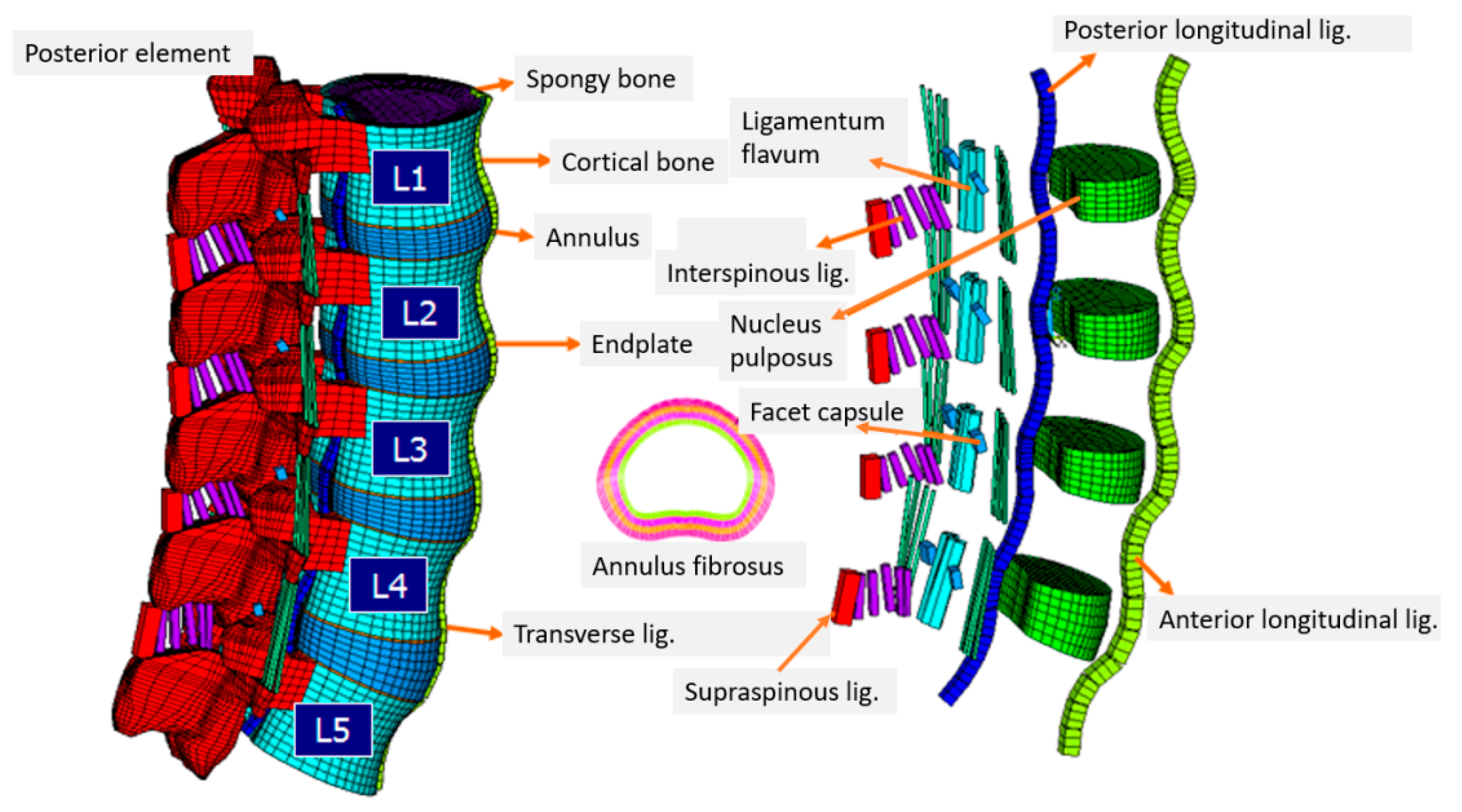
3.1. Intact Lumbar Spine
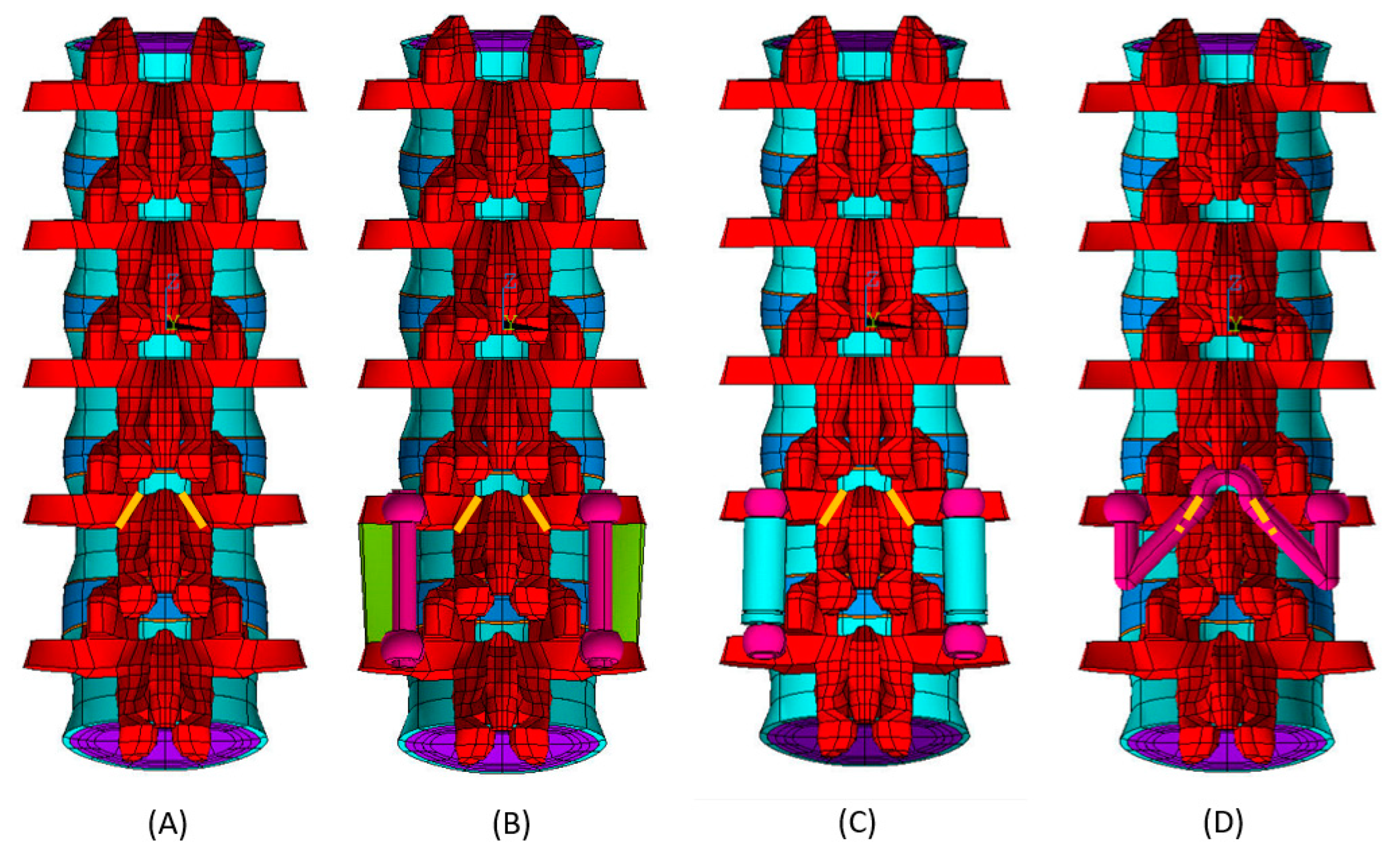
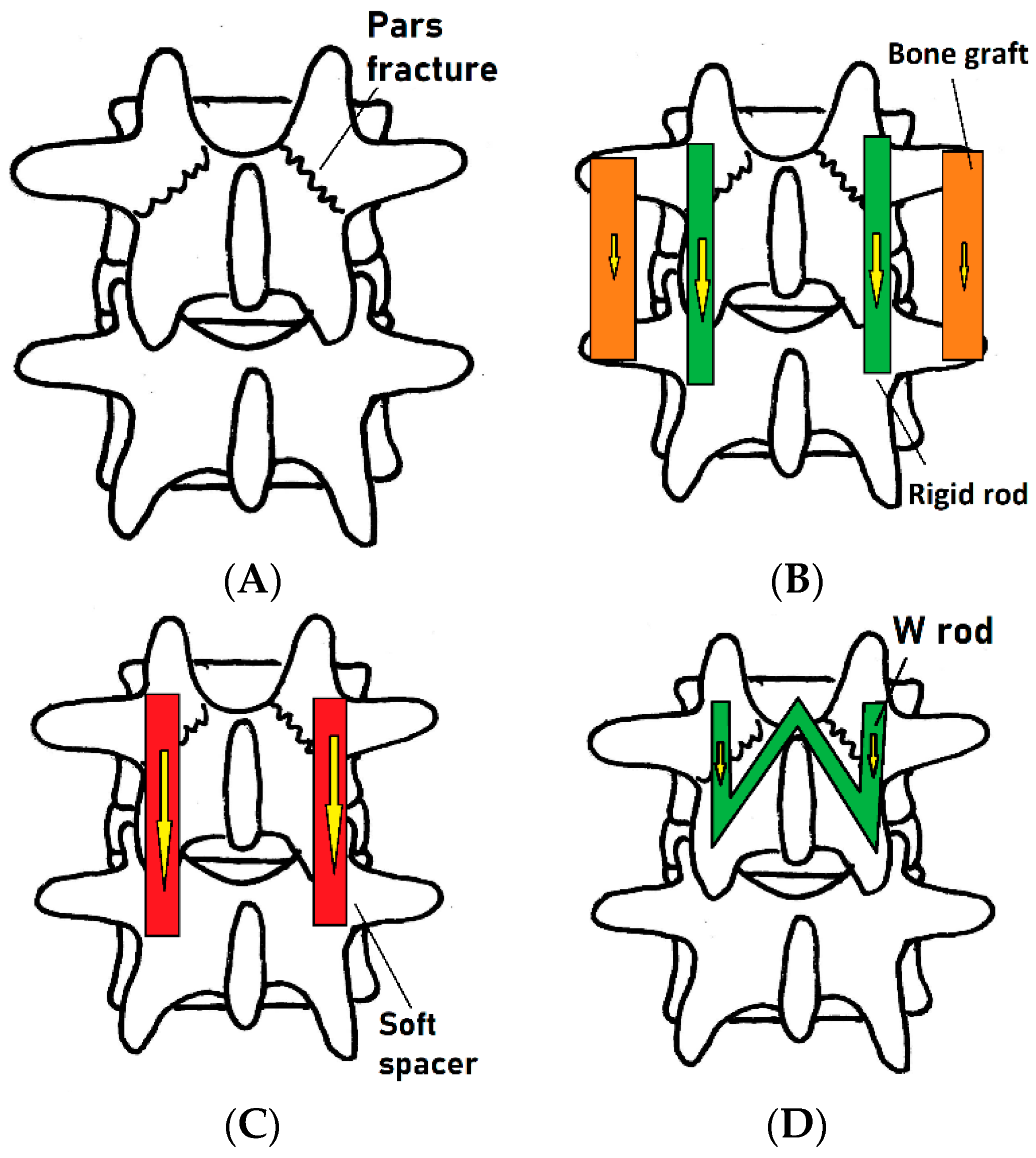
3.2. Lumbar Spine with Bilateral Pars Fractures
3.3. Bilateral Pars Fractures with Posterolateral Fusion
3.4. Bilateral Pars Fractures with Dynesys System
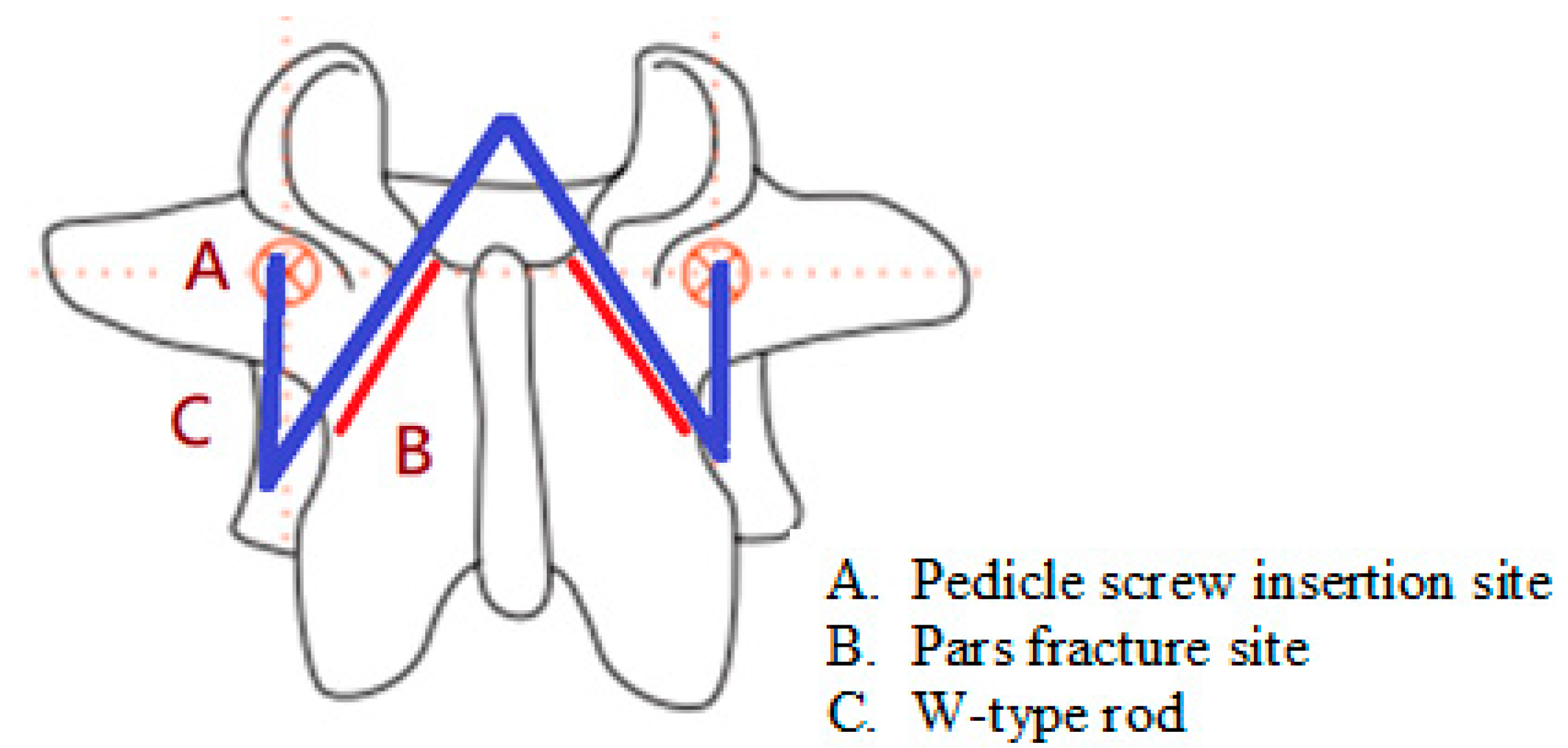
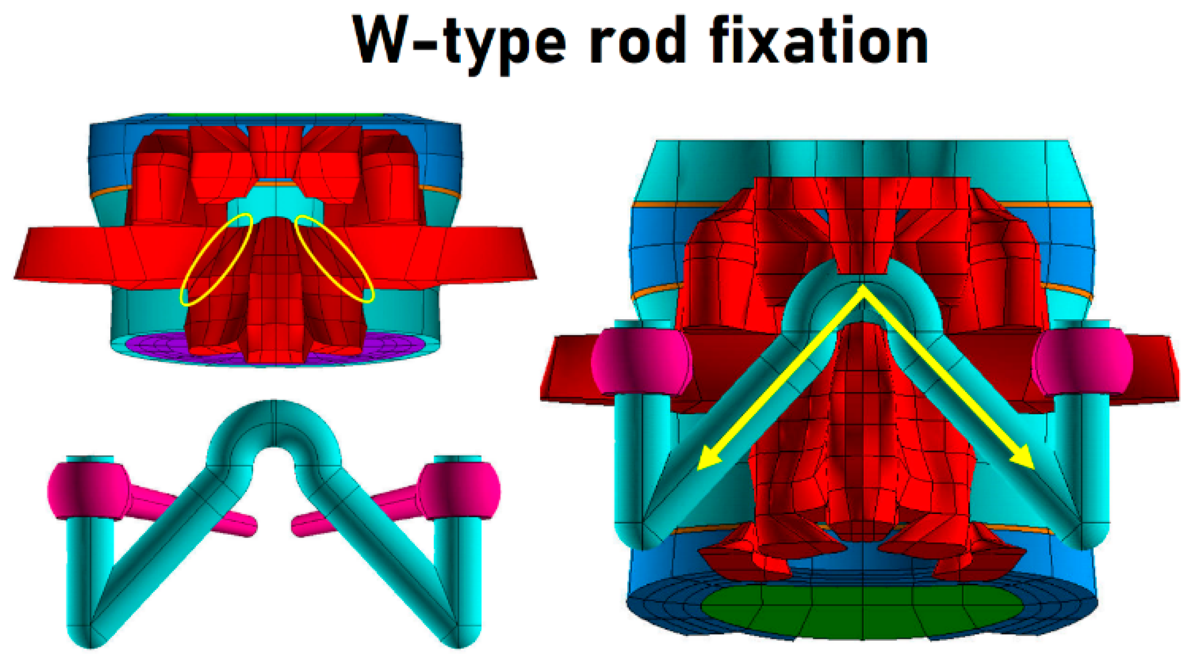
3.5. Bilateral Pars Fractures with Pedicle Screw W-Type Rod Fixation
3.6. Boundary and Loading Condition
- A 150 N normal axial load was applied to the superior surface of the L1 vertebrae.
- Bending moment was applied to the superior surface of the L1 vertebrae using the following parameters: flexion 19.9°, extension 12.3°, lateral bending 22.5°, and rotation 10.9°. The ROM comprised the maximum ranges of all FE models.
3.7. Biomechanical Evaluation
4. Results
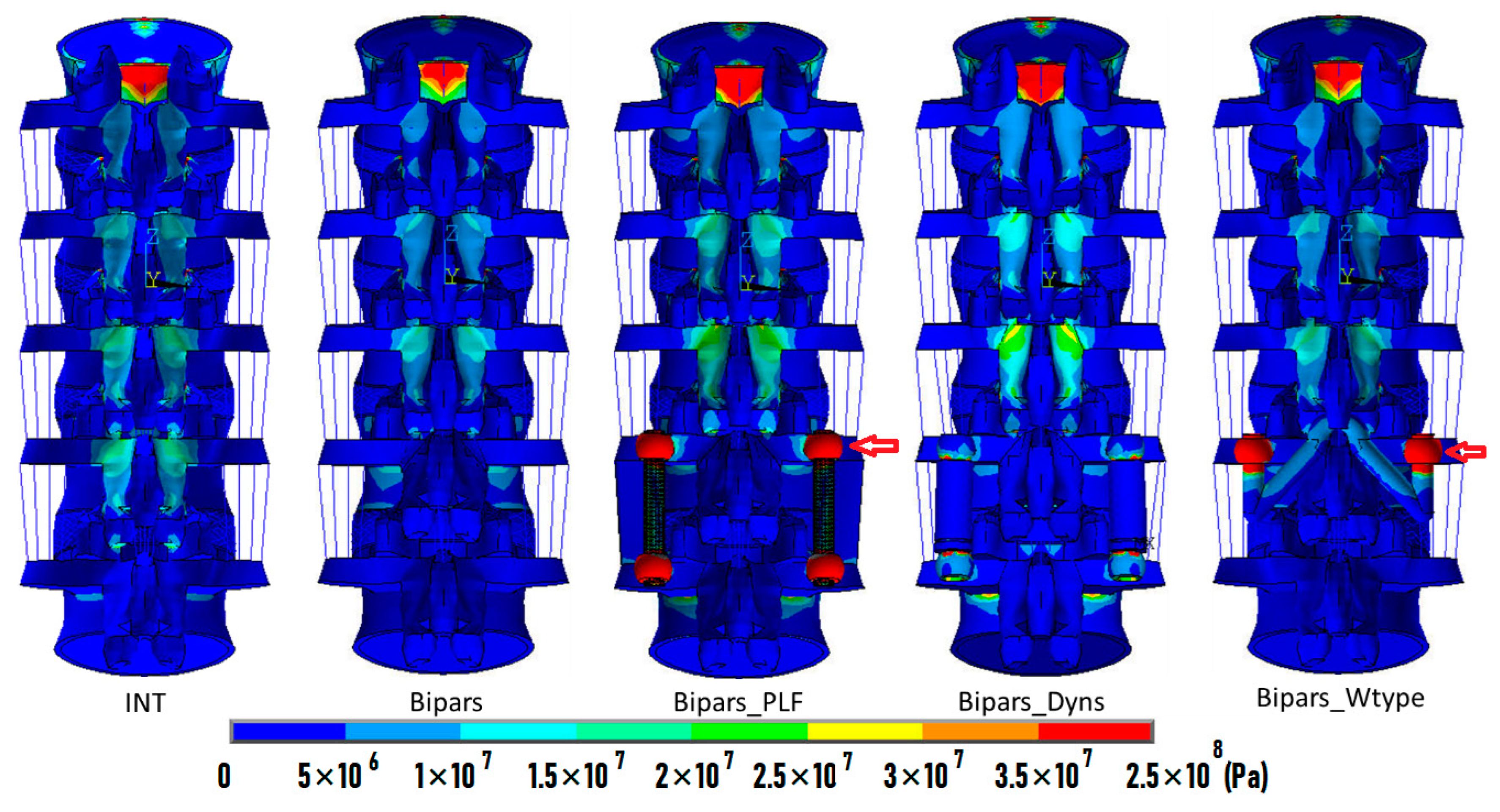
4.1. Flexion
4.2. Extension
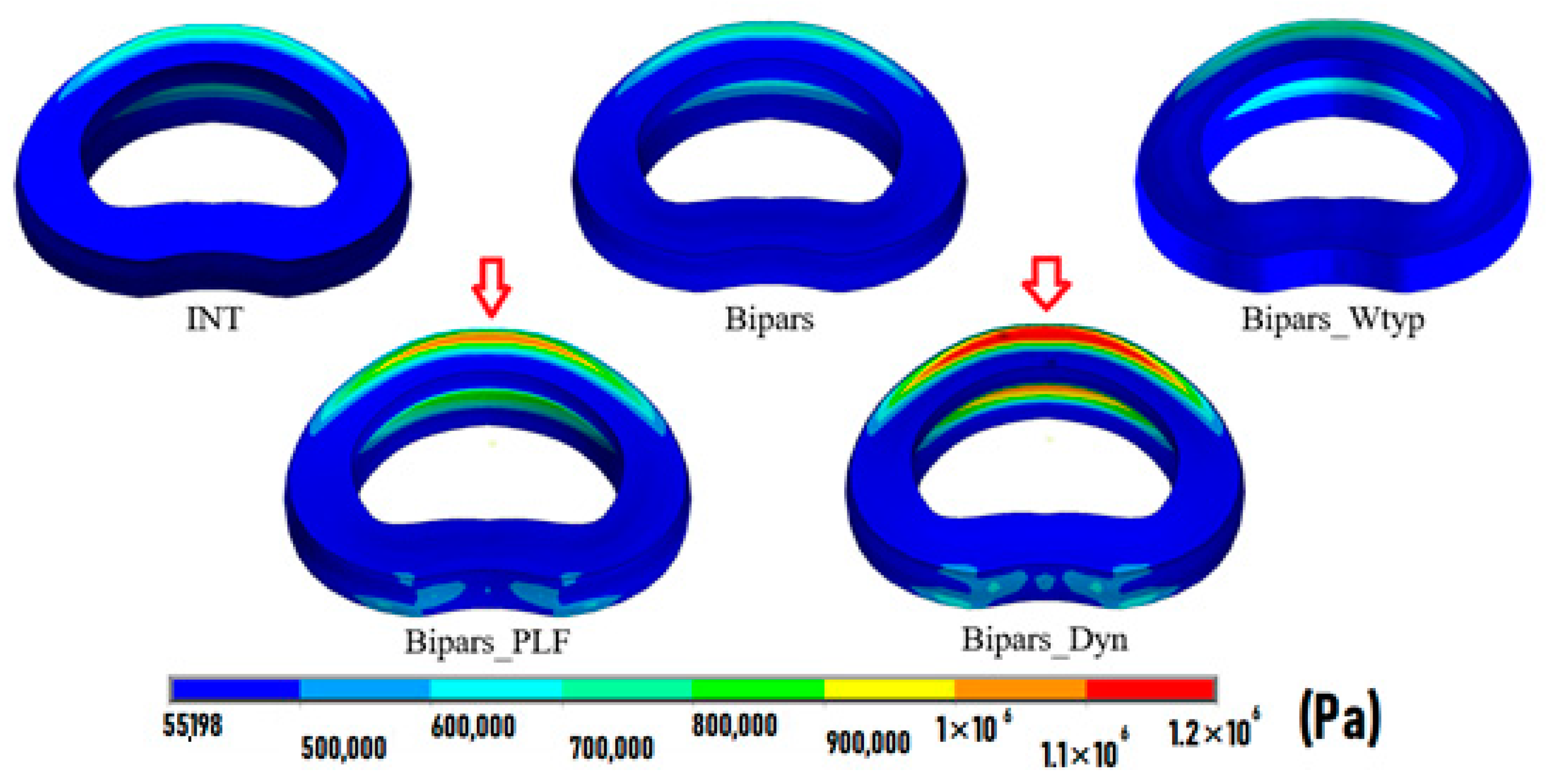
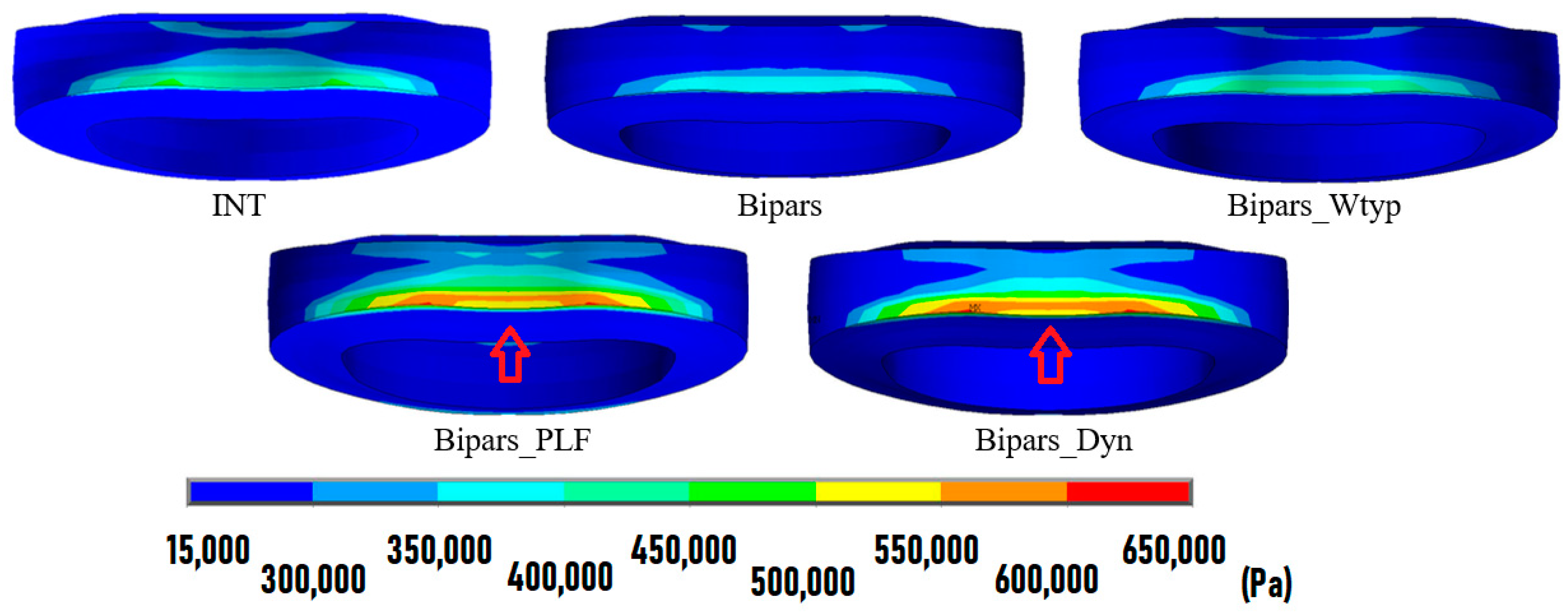
4.3. Lateral Bending
4.4. Rotation
5. Discussion
6. Conclusions
Author Contributions
Funding
Institutional Review Board Statement
Informed Consent Statement
Data Availability Statement
Conflicts of Interest
References
- Gagnet, P.; Kern, K.; Andrews, K.; Elgafy, H.; Ebraheim, N. Spondylolysis and spondylolisthesis: A review of the literature. J. Orthop. 2018, 15, 404–407. [Google Scholar] [CrossRef] [PubMed]
- Fredrickson, B.E.; Baker, D.; McHolick, W.J.; Yuan, H.A.; Lubicky, J.P. The natural history of spondylolysis and spondylolisthesis. J. Bone Jt. Surg. Am. Vol. 1984, 66, 699–707. [Google Scholar] [CrossRef]
- McCleary, M.D.; Congeni, J.A. Current concepts in the diagnosis and treatment of spondylolysis in young athletes. Curr. Sport. Med. Rep. 2007, 6, 62–66. [Google Scholar] [CrossRef]
- Frymoyer, J.W.; Cats-Baril, W.L. An overview of the incidences and costs of low back pain. Orthop. Clin. North Am. 1991, 22, 263–271. [Google Scholar] [CrossRef]
- van der Giezen, A.M.; Bouter, L.M.; Nijhuis, F.J.N. Prediction of return-to-work of low back pain patients sicklisted for 3–4 months. Pain 2000, 87, 285–294. [Google Scholar] [CrossRef] [Green Version]
- Morita, T.; Ikata, T.; Katoh, S.; Miyake, R. Lumbar spondylolysis in children and adolescents. J. Bone Jt. Surg. Br. Vol. 1995, 77, 620–625. [Google Scholar] [CrossRef]
- Sakai, T.; Tezuka, F.; Yamashita, K.; Takata, Y.; Higashino, K.; Nagamachi, A.; Sairyo, K. Conservative Treatment for Bony Healing in Pediatric Lumbar Spondylolysis. Spine 2017, 42, E716–E720. [Google Scholar] [CrossRef]
- Sri Vijay Anand, K.; Eamani, N.; Shetty, A.; Rajasekaran, S. Spondylolysis and pars repair technique: A comprehensive literature review of the current concepts. Indian Spine J. 2021, 4, 29–39. [Google Scholar] [CrossRef]
- Xing, R.; Dou, Q.; Li, X.; Liu, Y.; Kong, Q.; Chen, Q.; Gong, Q.; Zeng, J.; Liu, H.; Song, Y. Posterior Dynamic Stabilization With Direct Pars Repair via Wiltse Approach for the Treatment of Lumbar Spondylolysis: The Application of a Novel Surgery. Spine 2016, 41, E494–E502. [Google Scholar] [CrossRef] [PubMed] [Green Version]
- Koreckij, T.D.; Fischgrund, J.S. Degenerative Spondylolisthesis. J. Spinal Disord. Tech. 2015, 28, 236–241. [Google Scholar] [CrossRef] [PubMed]
- Gad Abdelkader, S.; El Zahlawy, H.N.; Elkhateeb, T.M. Interbody fusion versus posterolateral fusion in treatment of low grade lytic spondylolisthesis. Acta Orthop. Belg. 2019, 85, 269–273. [Google Scholar] [PubMed]
- Ghogawala, Z.; Dziura, J.; Butler, W.E.; Dai, F.; Terrin, N.; Magge, S.N.; Coumans, J.V.; Harrington, J.F.; Amin-Hanjani, S.; Schwartz, J.S.; et al. Laminectomy plus Fusion versus Laminectomy Alone for Lumbar Spondylolisthesis. New Engl. J. Med. 2016, 374, 1424–1434. [Google Scholar] [CrossRef] [PubMed]
- Ivanic, G.M.; Pink, T.P.; Achatz, W.; Ward, J.C.; Homann, N.C.; May, M. Direct stabilization of lumbar spondylolysis with a hook screw: Mean 11-year follow-up period for 113 patients. Spine 2003, 28, 255–259. [Google Scholar] [CrossRef] [PubMed]
- Debnath, U.K.; Scammell, B.E.; Freeman, B.J.C.; McConnell, J.R. Predictive Factors for the Outcome of Surgical Treatment of Lumbar Spondylolysis in Young Sporting Individuals. Glob. Spine J. 2018, 8, 121–128. [Google Scholar] [CrossRef] [PubMed] [Green Version]
- Debusscher, F.; Troussel, S. Direct repair of defects in lumbar spondylolysis with a new pedicle screw hook fixation: Clinical, functional and Ct-assessed study. Eur. Spine J. Off. Publ. Eur. Spine Soc. Eur. Spinal Deform. Soc. Eur. Sect. Cerv. Spine Res. Soc. 2007, 16, 1650–1658. [Google Scholar] [CrossRef] [Green Version]
- Grob, D.; Benini, A.; Junge, A.; Mannion, A.F. Clinical experience with the Dynesys semirigid fixation system for the lumbar spine: Surgical and patient-oriented outcome in 50 cases after an average of 2 years. Spine 2005, 30, 324–331. [Google Scholar] [CrossRef] [Green Version]
- Schnake, K.J.; Schaeren, S.; Jeanneret, B. Dynamic stabilization in addition to decompression for lumbar spinal stenosis with degenerative spondylolisthesis. Spine 2006, 31, 442–449. [Google Scholar] [CrossRef] [Green Version]
- Wang, J.P.; Zhong, Z.C.; Cheng, C.K.; Chen, C.S.; Yu, C.H.; Chang, T.K.; Wei, S.H. Finite element analysis of the spondylolysis in lumbar spine. Bio-Med. Mater. Eng. 2006, 16, 301–308. [Google Scholar]
- Han, X.; Chen, X.; Li, K.; Li, Z.; Li, S. Finite analysis of stability between modified articular fusion technique, posterior lumbar interbody fusion and posteriorlateral lumbar fusion. BMC Musculoskelet. Disord. 2021, 22, 1015. [Google Scholar] [CrossRef]
- Demir, E.; Eltes, P.; Castro, A.P.; Lacroix, D.; Toktaş, İ. Finite element modelling of hybrid stabilization systems for the human lumbar spine. Proc. Inst. Mech. Eng. Part H J. Eng. Med. 2020, 234, 1409–1420. [Google Scholar] [CrossRef]
- Shih, S.L.; Liu, C.L.; Huang, L.Y.; Huang, C.H.; Chen, C.S. Effects of cord pretension and stiffness of the Dynesys system spacer on the biomechanics of spinal decompression—A finite element study. BMC Musculoskelet. Disord. 2013, 14, 191. [Google Scholar] [CrossRef] [Green Version]
- Lo, H.J.; Chen, C.S.; Chen, H.M.; Yang, S.W. Application of an interspinous process device after minimally invasive lumbar decompression could lead to stress redistribution at the pars interarticularis: A finite element analysis. BMC Musculoskelet. Disord. 2019, 20, 213. [Google Scholar] [CrossRef]
- Zhong, Z.C.; Hung, C.; Lin, H.M.; Wang, Y.H.; Huang, C.H.; Chen, C.S. The influence of different magnitudes and methods of applying preload on fusion and disc replacement constructs in the lumbar spine: A finite element analysis. Comput. Method Biomech. Biomed. Eng. 2013, 16, 943–953. [Google Scholar] [CrossRef] [PubMed]
- Chen, S.H.; Zhong, Z.C.; Chen, C.S.; Chen, W.J.; Hung, C. Biomechanical comparison between lumbar disc arthroplasty and fusion. Med. Eng. Phys. 2009, 31, 244–253. [Google Scholar] [CrossRef] [PubMed]
- Shirazi-Adl, A.; Ahmed, A.M.; Shrivastava, S.C. Mechanical response of a lumbar motion segment in axial torque alone and combined with compression. Spine 1986, 11, 914–927. [Google Scholar] [CrossRef]
- Lee, J.; Ehara, S.; Tamakawa, Y.; Shimamura, T. Spondylolysis of the upper lumbar spine. Radiological features. Clin. Imaging 1999, 23, 389–393. [Google Scholar] [CrossRef] [PubMed]
- Fan, J.; Yu, G.R.; Liu, F.; Zhao, J.; Zhao, W.D. A biomechanical study on the direct repair of spondylolysis by different techniques of fixation. Orthop. Surg. 2010, 2, 46–51. [Google Scholar] [CrossRef] [PubMed]
- Cheh, G.; Bridwell, K.H.; Lenke, L.G.; Buchowski, J.M.; Daubs, M.D.; Kim, Y.; Baldus, C. Adjacent segment disease followinglumbar/thoracolumbar fusion with pedicle screw instrumentation: A minimum 5-year follow-up. Spine 2007, 32, 2253–2257. [Google Scholar] [CrossRef]
- Ma, J.; Jia, H.; Ma, X.; Xu, W.; Yu, J.; Feng, R.; Wang, J.; Xing, D.; Wang, Y.; Zhu, S.; et al. Evaluation of the stress distribution change at the adjacent facet joints after lumbar fusion surgery: A biomechanical study. Proc. Inst. Mech. Eng. Part H J. Eng. Med. 2014, 228, 665–673. [Google Scholar] [CrossRef]
- Kim, C.H.; Chung, C.K.; Jahng, T.A. Comparisons of outcomes after single or multilevel dynamic stabilization: Effects on adjacent segment. J. Spinal Disord. Tech. 2011, 24, 60–67. [Google Scholar] [CrossRef]
- Schaeren, S.; Broger, I.; Jeanneret, B. Minimum four-year follow-up of spinal stenosis with degenerative spondylolisthesis treated with decompression and dynamic stabilization. Spine 2008, 33, E636–E642. [Google Scholar] [CrossRef] [PubMed] [Green Version]
- Shih, S.L.; Chen, C.S.; Lin, H.M.; Huang, L.Y.; Liu, C.L.; Huang, C.H.; Cheng, C.K. Effect of spacer diameter of the Dynesys dynamic stabilization system on the biomechanics of the lumbar spine: A finite element analysis. J. Spinal Disord. Tech. 2012, 25, E140–E149. [Google Scholar] [CrossRef] [PubMed]
- Ulibarri, J.A.; Anderson, P.A.; Escarcega, T.; Mann, D.; Noonan, K.J. Biomechanical and clinical evaluation of a novel technique for surgical repair of spondylolysis in adolescents. Spine 2006, 31, 2067–2072. [Google Scholar] [CrossRef]
- Hsieh, J.Y.; Chen, C.S.; Chuang, S.M.; Wang, J.H.; Chen, P.Q.; Huang, Y.Y. Finite element analysis after rod fracture of the spinal hybrid elastic rod system. BMC Musculoskelet. Disord. 2022, 23, 816. [Google Scholar] [CrossRef]
- Hsu, F.C.; Chen, C.S.; Yao, Y.C.; Lin, H.H.; Wang, S.T.; Chang, M.C.; Liu, C.L.; Chou, P.H. Shorter screw lengths in dynamic Dynesys fixation have less screw loosening: From clinical investigation to finite element analysis. J. Chin. Med. Assoc. 2022, 86, 330–337. [Google Scholar] [CrossRef]
- Hsieh, J.Y.; Chen, C.S.; Chuang, S.M.; Chen, P.Q.; Huang, Y.Y. Comparison of the optimal design of spinal hybrid elastic rod for dynamic stabilization: A finite element analysis. Appl. Sci. 2022, 12, 11759. [Google Scholar] [CrossRef]
- Wei, H.W.; Chuang, S.M.; Chen, C.S. Biomechanical analysis of the lumbar spine by using a new interspinous process device: A finite element analysis. Appl. Sci. 2021, 11, 10486. [Google Scholar] [CrossRef]
- Chen, C.S.; Shih, S.L. Biomechanical analysis of a new lumbar interspinous device with topology optimization. Med. Bio. Eng. Comput. 2018, 56, 1331–1341. [Google Scholar] [CrossRef]
- Hsieh, J.Y.; Chuang, S.M.; Chen, C.S.; Wang, J.H.; Chen, P.Q.; Huang, Y.Y. Novel modular spine blocks affect the lumbar spine on finite element analysis. Spine Surg. Relat. Res. 2022, 6, 533–539. [Google Scholar] [CrossRef]
- Ammarullah, M.I.; Gatot Santoso, G.; Sugiharto, S.; Supriyono, T.; Wibowo, D.B.; Kurdi, O.; Tauviqirrahman, M.; Jamari, J. Minimizing risk of failure from ceramic-on-ceramic total hip prosthesis by selecting ceramic materials based on Tresca stress. Sustainability 2022, 14, 13413. [Google Scholar] [CrossRef]
- Jamari, J.; Ammarullah, M.I.; Saad, A.P.M.; Syahrom, A.; Uddin, M.; van der Heide, E.; Basri, H. The effect of bottom profile dimples on the femoral head on wear in metal-on-metal total hip Arthroplasty. J. Funct. Biomater. 2021, 12, 38. [Google Scholar] [CrossRef] [PubMed]


| Material | Element Type | Young’s Modulus (MPa) | Poisson’s Ratio |
|---|---|---|---|
| Titanium alloy screw | 8-node SOLID185 | 110,000 | 0.28 |
| PCU spacer | 8-node SOLID185 | 68.4 | 0.4 |
| PET cord | 2-node LINK10 | 1500 | 0.4 |
| INT | Bipars | Bipars_PLF | Bipars_Dyn | Bipars_Wtype | |
|---|---|---|---|---|---|
| Loading moment (Nm) | 9.6 | 9.6 | 12.0 | 12.3 | 9.9 |
| L4-L5 ROM (degree) | 5.98 (0%) | 6.17 (+3%) | 2.10 (−65%) | 1.37 (−77%) | 5.48 (−8%) |
| L3-L4 adjacent disc stress (KPa) | 780 (0%) | 772 (−2%) | 1100 (+40%) | 1190 (+51%) | 819 (+4%) |
| L3-L4 adjacent FCF (N) | 0 | 0 | 0 | 0 | 0 |
| INT | Bipars | Bipars_PLF | Bipars_Dyn | Bipars_Wtyp | |
|---|---|---|---|---|---|
| Loading moment (Nm) | 9.0 | 7.5 | 11.7 | 10.8 | 8.4 |
| L4-L5 ROM (degree) | 3.05 (0%) | 4.36 (+43%) | 0.81 (−73%) | 1.90 (−38%) | 3.78 (+24%) |
| L3-L4 adjacent disc stress (KPa) | 473 (0%) | 401 (−15%) | 612 (+29%) | 562 (+19%) | 437 (−8%) |
| L3-L4 adjacent FCF (N) | 81 (0%) | 64 (−21%) | 107 (+32%) | 96 (+19%) | 72 (−11%) |
| INT | Bipars | Bipars_PLF | Bipars_Dyn | Bipars_Wtyp | |
|---|---|---|---|---|---|
| Loading moment (Nm) | 11.7 | 11.7 | 14.1 | 13.2 | 12.0 |
| L4-L5 ROM (degree) | 4.94 (0%) | 5.12 (+4%) | 1.27 (−74%) | 2.42 (−51%) | 4.28 (−13%) |
| L3-L4 adjacent disc stress (KPa) | 997 (0%) | 991 (−1%) | 1210 (+21%) | 1130 (+13%) | 1030 (+3%) |
| Left/Right L3-L4 adjacent FCF (N) | 12/1 | 10/0 | 38/14 | 22/7 | 17/4 |
| INT | Bipars | Bipars_PLF | Bipars_Dyn | Bipars_Wtyp | |
|---|---|---|---|---|---|
| Loading moment (Nm) | 9.9 | 7.8 | 13.5 | 9.0 | 9.0 |
| L4-L5 ROM (degree) | 3.76 (0%) | 4.73 (+26%) | 2.13 (−43%) | 3.96 (+5%) | 4.20 (+11%) |
| L3-L4 adjacent disc stress (KPa) | 387 (0%) | 338 (−13%) | 489 (+26%) | 384 (−1%) | 374 (−3%) |
| Left/Right L3-L4 adjacent FCF (N) | 0/124 | 0/90 | 0/172 | 0/110 | 0/113 |
Disclaimer/Publisher’s Note: The statements, opinions and data contained in all publications are solely those of the individual author(s) and contributor(s) and not of MDPI and/or the editor(s). MDPI and/or the editor(s) disclaim responsibility for any injury to people or property resulting from any ideas, methods, instructions or products referred to in the content. |
© 2023 by the authors. Licensee MDPI, Basel, Switzerland. This article is an open access article distributed under the terms and conditions of the Creative Commons Attribution (CC BY) license (https://creativecommons.org/licenses/by/4.0/).
Share and Cite
Pan, J.-H.; Chen, C.-S.; Liu, C.-L.; Chou, P.-H. Biomechanical Effects of a Novel Pedicle Screw W-Type Rod Fixation for Lumbar Spondylolysis: A Finite Element Analysis. Bioengineering 2023, 10, 451. https://doi.org/10.3390/bioengineering10040451
Pan J-H, Chen C-S, Liu C-L, Chou P-H. Biomechanical Effects of a Novel Pedicle Screw W-Type Rod Fixation for Lumbar Spondylolysis: A Finite Element Analysis. Bioengineering. 2023; 10(4):451. https://doi.org/10.3390/bioengineering10040451
Chicago/Turabian StylePan, Jo-Hsi, Chen-Sheng Chen, Chien-Lin Liu, and Po-Hsin Chou. 2023. "Biomechanical Effects of a Novel Pedicle Screw W-Type Rod Fixation for Lumbar Spondylolysis: A Finite Element Analysis" Bioengineering 10, no. 4: 451. https://doi.org/10.3390/bioengineering10040451