Article

Advances in the Separation of Graphite from Lithium Iron Phosphate from End-of-Life Batteries Shredded Fine Fraction Using Simple Froth Flotation

Sustainable Materials Management, Flemish Institute for Technological Research (VITO), Boeretang 200, B-2400 Mol, Belgium
*
Authors to whom correspondence should be addressed.
Batteries 2023, 9(12), 589; https://doi.org/10.3390/batteries9120589
Submission received: 10 November 2023 / Revised: 7 December 2023 / Accepted: 10 December 2023 / Published: 13 December 2023

Abstract

:
Olivine-type lithium iron phosphate (LiFePO4, LFP) lithium-ion batteries (LIBs) have become a popular choice for electric vehicles (EVs) and stationary energy storage systems. In the context of recycling, this study addresses the complex challenge of separating black mass of spent LFP batteries from its main composing materials to allow for direct recycling. In this study, 71% copper and 81% aluminium foil impurities were removed by sieving black mass to <250 µm. Next, the application of froth flotation as a separation technique was explored, examining the influence of chemical agents, pre-treatment, and multi-step processes. Frother agent addition improved material recovery in the froth, while collector addition influenced the separation efficiency and enhanced graphite recovery. Pre-treatment, particularly sonication, was found to break down agglomerates and further improve separation. Multi-step flotation increased the purity of recovered fractions. The optimized process for a black mass < 250 µm, involving sonication pre-treatment and double flotation, resulted in enriched carbonaceous material (80.3 mol%) in froth fractions and high LFP concentration (81.9 mol%) in tailings fractions. The recovered spent LFP cathode material contained 37.20 wt% Fe2P2O7, a degradation product of LiFePO4. This research offers valuable insights for the development of efficient battery recycling methods for LFP batteries.

Graphical Abstract

1. Introduction

In the last decade, electric vehicles (EVs) and stationary energy storage systems have gained in popularity and are thought to be one of the primary solutions towards a more sustainable transportation and energy sector. This transition is powered by lithium-ion batteries (LIBs) that can take various forms and be of very varied composition. Consequently, the amount of spent LIBs is predicted to grow exponentially, which creates some waste management issues. To attain a 54% recycling rate of end-of-life batteries by 2030, the global battery alliance projects of the World Economic Forum predicts a need to increase the recycling facilities for LIBs by 25-fold [1].
Current recycling processes for LIBs focus on the recovery of precious metals (Co and Ni, mainly) from popular cathode materials, such as LiCoO2 (LCO), NMC (LiNixMnyCo1−x−yO2), and NCA (LiNi0.8Co0.15Al0.05O2) [2,3,4,5]. To achieve this, two types of processes are used: pyrometallurgy and hydrometallurgy [3,6,7]. Although they differ in many aspects, the common ground between the two is the recovery of the metals in a high-purity elemental, oxide, or salt form [7]. This means that in order to produce battery grade material form the recycling process, a thorough refining step is needed. This is not only costly in time but also in energy, and results in the side production of harmful substances or emissions [8]. This process is also not suitable for Co- and Ni-free cathode materials as the economic value of the contained individual elements is too small to make the recycling process viable. One such LIB type is the olivine-type lithium iron phosphate (LiFePO4, LFP), which has recently gained popularity in its use in both EVs and stationary energy storage applications. This is mainly due to its advantageous low price, high stability, and good electrochemical properties [9]. Numerous Chinese car companies are already selling cars equipped with this type of battery, although no large scale recycling process has been developed yet [10].
An alternative recycling route that has been studied and favoured in recent years is direct recycling [11,12,13,14,15]. This method focuses on rejuvenating the spent active battery material into a fresh one without its destruction. This then becomes much more interesting for the valuable metal free cathode materials as the process will not require many laborious refining steps and the recovered active cathode (or anode) material has a higher economic value than its individual raw materials [16]. A common way to use direct recycling is by re-lithiathion of the spent material in a high temperature sintering step [17,18,19,20]. However, this requires a precise knowledge of the Li deficiency as well as a precise control of the annealing temperature and time [21,22,23]. In recent years, this process has evolved to a lower temperature process utilizing reducing agents and Li sources under near ambient conditions or hydrothermal conditions [24,25,26]. Graphite has received little attention with regards to the cathodic materials. However, recycling of graphite is starting to be researched in greater detail and two main routes have been identified: (1) the regeneration of graphite for LIB application and (2) graphite-based material synthesis using the spent material. For the regeneration, leaching and heat treatment are the primarily investigated routes [27,28].
Direct recycling requires that the spent cathode and anode materials are a priori separated and purified, which is currently not performed. In a classical recycling process for LIBs, the batteries are first discharged, disassembled from their casing, shredded, and then processed. Sometimes, prior to shredding, a pyrolysis step is added to remove organic materials such as the binder and electrolyte solvent. Whereas, after the shredding step, some physical separation methods, i.e., mainly sieving, are used to recover the Al and Cu foils leaving a black mass (BM) composed of a mixture of the anode and cathode active materials with small impurities of the current collector foils and binder [29]. As the active materials have small particle sizes (typically <200 µm) [30], most physical separation methods are unsuitable to separate them. However, graphite and LFP present different physico-chemical properties including opposite hydrophobicity [31]. A common separation method that exploits this property to separate fine-grained materials is called froth flotation.
Froth flotation is a separation process that relies on the differences in surface hydrophobicity of different materials [32]. It is used extensively at industrial scale to separate valuable materials from ores [33,34,35,36,37]. The process consists of precisely controlling the particles hydrophobicity so that only the most hydrophobic attach to the air bubbles rising in the aqueous media [38]. This process is suitable for separating fine particles but requires a good control of various parameters including the air flow rate, the mixing speed, the pH, and many more. Although naturally hydrophobic materials such as graphite can generally be readily separated, small amounts of chemical agents are, by and large, used to enhance the separation [39]. The function of these chemicals is to enhance the hydrophobic nature of the material to be floated in the foam (collector) [40] as well as to augment the stability of the froth by modifying the surface tension (frother) [41]. Furthermore, inhibitors can be used to suppress the hydrophobic nature of some surfaces. The pH of the solution is also of crucial importance since some minerals will only float at distinct pH values; thus, pH regulators are often used [42].
Most publications focusing on the separation of the components of the black mass by flotation use a simulated compound where virgin graphite and LFP are mixed together in the appropriate ratio [35]. Black mass obtained from end-of-life (EoL) batteries through existing shredding processes contain a significant amount of impurities (e.g., binder material, electrolyte residues, current collector foil residues, etc.) and the physicochemical properties of anode and cathode materials are often altered through agglomeration and chemical degradation. Therefore, artificially composed graphite-LFP-mixtures are often not representative for real EoL batteries black mass materials. The current studies based on real black mass also present some flaws. In fact, most studies disassemble the batteries by hand to separate and recover the anode and cathode materials separately, after which they were recomposed [33,43]. Although this method is more representative as it deals with spent black mass, it is impractical to consider for a larger scale operation. In fact, the disassembly methods and pre-treatment that would be operated at larger scale are very likely to introduce some unforeseen challenges such as more cross-contamination, fusing of the different material under pyrolysis conditions, residual binders, and electrolyte materials, etc. (See Table 1).
This study aims to separate, by froth flotation, a representative black mass sample from collected end-of-life LFP batteries into a graphite-rich and an LFP-rich fraction. Obtaining such purified fractions enables direct recycling of the active battery anode and cathode materials, respectively. The black mass was obtained from an industrial battery recycling process that consecutively pyrolyzed, shredded, and sieved a batch of collected spent LFP batteries. Froth flotation was applied to the black mass and the effects of chemical flotation agents (frother, collector), pH, and pre-treatment on the separation efficiency were tested and optimised. Finally, multiple subsequent flotation steps were applied to allow for further purification of the tailings and froth fractions.

2. Materials and Methods

2.1. Materials

The black mass employed in the experiments was provided by Accurec Recycling GmbH (Krefeld, Germany). The spent LFP battery cells were initially subjected, by means of a proprietary industrial process, to a thermal treatment < 600 °C under inert atmosphere to pyrolyze the organic materials (e.g., plastics, electrolyte solvents, binder material) and hydrolyse the electrolyte salts. By doing so, potentially harmful pyrolysis products can be removed and separated via an off-gas treatment system [53] and the detachment of the black mass from the cell’s current collector foils improved. Then, a subsequent mechanical treatment, including shredding and sieving, allowed for the separation of the resulting mixture of black mass, Cu/Al collector foils, and/or ferrous metals. This work focuses on the treatment of the obtained black mass.
The reagents used in froth flotation and pre-treatment experiments were n-dodecane (for synthesis ≥ 99%, Merck (Darmstadt, Germany)), methylisobutylcarbinol ((MIBC) ACS reagent grade ≥ 98.5%, Merck). The pH was adjusted with sodium hydroxide (ACS reagent ≥ 97% Merck, NaOH) and hydrochloric acid (ACS reagent 37% HCl, Merck). All chemicals were of analytical grade and used as received.

2.2. Methods

Prior to flotation, starting materials were sieved to below a desired particle size threshold (<125 µm for initial testing and <250 µm for optimization). A Denver Equipment D12 flotation cell was used for all the flotation tests, with an impeller speed of 1200 rpm. For the flotation experiment, 40 g/L of sieved black mass was placed in the flotation cell with water and stirred for 3 min for conditioning. Then, pH regulator, inhibitor, collector, and frother were added in the same order and conditioned for 3 min each. Air was added at a rate of 2 L/min in order to obtain a persistent foam. The foam was collected for 3 min and is designated as “froth”. The remaining material left in the flotation cell is designated as “tailings”. Both froth and tailing fractions were filtered, dried at 70 °C for 24 h, and weighed. For the sonication pre-treatment experiments, a Bandelin Sonorec sonicator type RK514 at 35 kHz was used.
Based on the literature shown in Table 1, the frothing agent was selected as methylisobutylcarbinol (MIBC) and the collector as n-dodecane.
The multi-stage flotation process has been introduced to enhance and increase the separation yield of the two electrode materials. Each of the recovered fractions (froth and tailings) were subjected to a new flotation process with slight adjustments of the parameters. This process results in four different fractions obtained. For ease of understanding, the different fractions are designated using a two letters’ system. The first letter corresponds to the origin of the fraction (aka, which fractions was it from the first process) and includes the letter “T” for the tailings and “F” for the froth. Similarly, the second letter corresponds to the faction of the second flotation and includes the same letter as before. For example, “TF” designates the froth obtained from the flotation performed on the tailings of the first process. Similarly, “FF” designates the froth obtained from the flotation operated on the froth from the first process, etc. (see Figure S13).

2.3. Analyses

Elemental analyses of all solid samples were performed by a handheld XRF analyser Niton XL3t GOLDD+, equipped with an Ag anode (50 kV and 0.2 mA). The XRF analyser was placed in a mobile test stand and a measuring time of 120 s was applied for each sample. The carbon content was calculated using the Equation (1).
C w t % = B a l w t % F e w t % M M F e · M M L i + M M O × 4
where MM = molar mass of the specified element and Bal is the balance value obtained, this accounts for the light elements that cannot be measured by XRF (i.e., typically from H up to Ne in the periodic system). In the case of the LFP black mass, it can be assumed that the light elements present in the material and not measured by XRF are mainly Li, C, and O. The LiFePO4 content was approximated by basing it on the Fe concentration measured and converted into molar concentration by assuming that all measured Fe is present in the samples as LiFePO4. This derivation of the carbon content based on XRF measurements was in good agreement with total carbon content measurements performed on a series of black mass samples.
To calculate the composition of the obtained fraction, the Equations (2) and (3) were used.
L F P   ( m o l % ) = F e   ( w t % ) M M F e + P   ( w t % ) M M P + B a l * ( M M L i + M M O )
where Bal* = Bal (wt%) − C (wt%)
C   ( m o l % ) = C   ( w t % ) M M C
The starting material and the finally obtained LFP-rich fraction after optimization were analysed using a high-performance energy dispersive XRF spectrometer with polarized X-ray excitation geometry (HE XEPOS, Spectro Analytical Systems, Kleve, Germany). The instrument was equipped with a 50 W tungsten end window tube (max. 60 kV, 2 mA) and a Silicon Drift Detector. For signal optimization, different targets were applied. All analyses were performed under He atmosphere. The elemental composition of the samples was also determined with inductively coupled plasma—atomic emission spectrometry (ICP-AES) after acid digestion using a microwave system according to EN 13656. The digested solution was measured with an ICP-AES (Perkin Elmer, Optima 3000 DV). Total carbon content (TC) was determined by infrared detection after incineration. The device used for the analysis is an Analytikjena multi EA4000 elemental analyser. X-ray powder diffraction was carried out with a PANalytical Empyrean system, operated at 40 kV and 45 mA, with Co tube (fine focus, λ = 1.7903 Å). Continuous scans with a step size rate of 0.013°/49.725 s were performed within a 2θ range of 5°–120° (2D-detector). The obtained diffractograms were quantitatively analysed with the aid of HighScore Plus software (version 4.6a). The particle size distribution was determined by laser diffraction using a Malvern Mastersizer X laser diffraction particle size analyser. A polydisperse mode of analysis with air as dispersant and a particle refractive index of 1.4500 with an adsorption of 0.1 were chosen. Scanning electron microscopy (SEM) and energy dispersive spectroscopy (EDS) were used to determine the composition, elemental distribution, and morphology of epoxy embedded powder samples. A FEI Quanta 200 scanning electron microscope equipped with a Bruker XFlash 4030 EDS detector was used.

3. Results

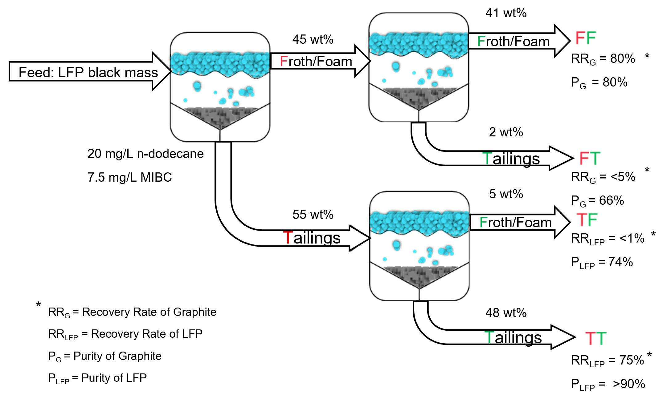
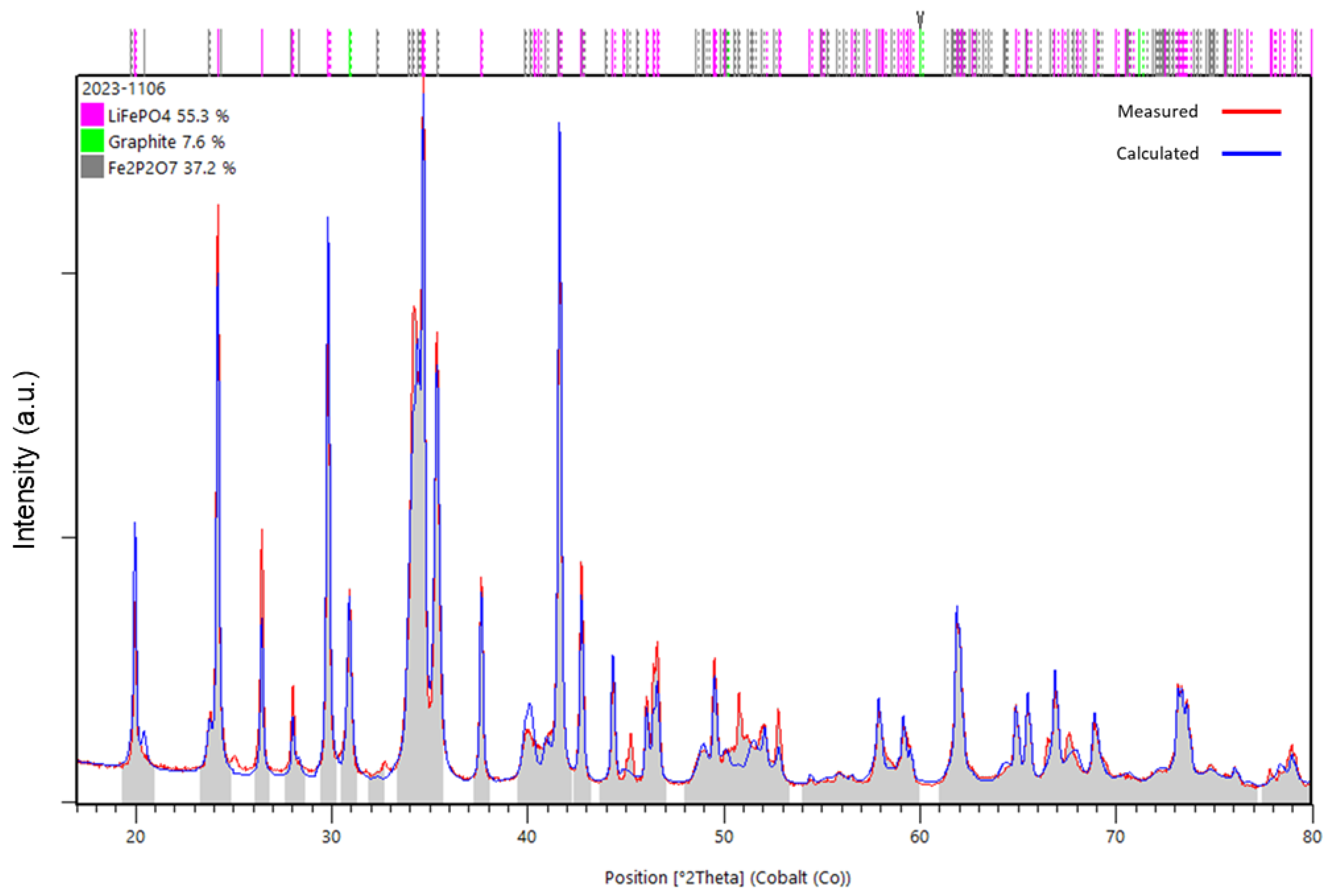
3.1. Black Mass Characterization

The as received black mass was characterized by means of X-ray fluorescence (XRF) and inductive-coupled plasma atomic emission spectrometry (ICP-AES) to determine the chemical composition and total carbon analyses were also executed. In the case of XRF measurements, the obtained balance value was used to estimate the total carbon concentration as explained in the Analysis section. Table 2 describes the different results obtained by both techniques.
As it can be observed, the results are similar, yet not equal. Indeed, the XRF analyses tends to overestimate certain elements (such as Fe, C, and the balance) and underestimate others (such as Al, Cu, and P). A visual inspection of the received samples seemed to indicate that the leftover impurities of copper and aluminium sheets had a larger particle size than the rest of the black mass. Figure 1A shows optical photographs taken after sieving the received sample. It can be noticed that in the fractions below 125 µm, only black material can be observed. In the two larger fractions copper- and aluminium-coloured foils could be detected. Very few were present in the fraction between 125 µm and 250 µm but they seem to dominate the fraction > 250 µm. This was later confirmed by conducting XRF analysis. Figure 1B) depicts the results for the XRF analysis realized on all the fraction of dry-sieved back mass (further details are provided in Table S1). The particle size distribution of the black mass can be found in Figures S2 and S8. Several observations could be made. First, <63 µm fraction was the richest in carbon. However, this fraction still contained a significant percentage of iron. Second, one could observe that Cu contamination only starts to appear as of the fraction from 125–250 µm, yet in very small quantities (1.12 wt%). Last, the proportion of Cu and Al present takes a very significant percentage of the mass once the particle size exceeds 250 µm, even reaching a combined 70.40 wt% of the sample in the fraction >500 µm. This indicates that a first step to achieve and efficient separation and limit the contamination of the obtained material can be a simple dry sieving procedure in which only the material with a particle size < 250 µm was treated by froth flotation. However, for the first test, it was decided to limit the contamination even further and only use material with particle size < 125 µm.

3.2. Froth Flotation

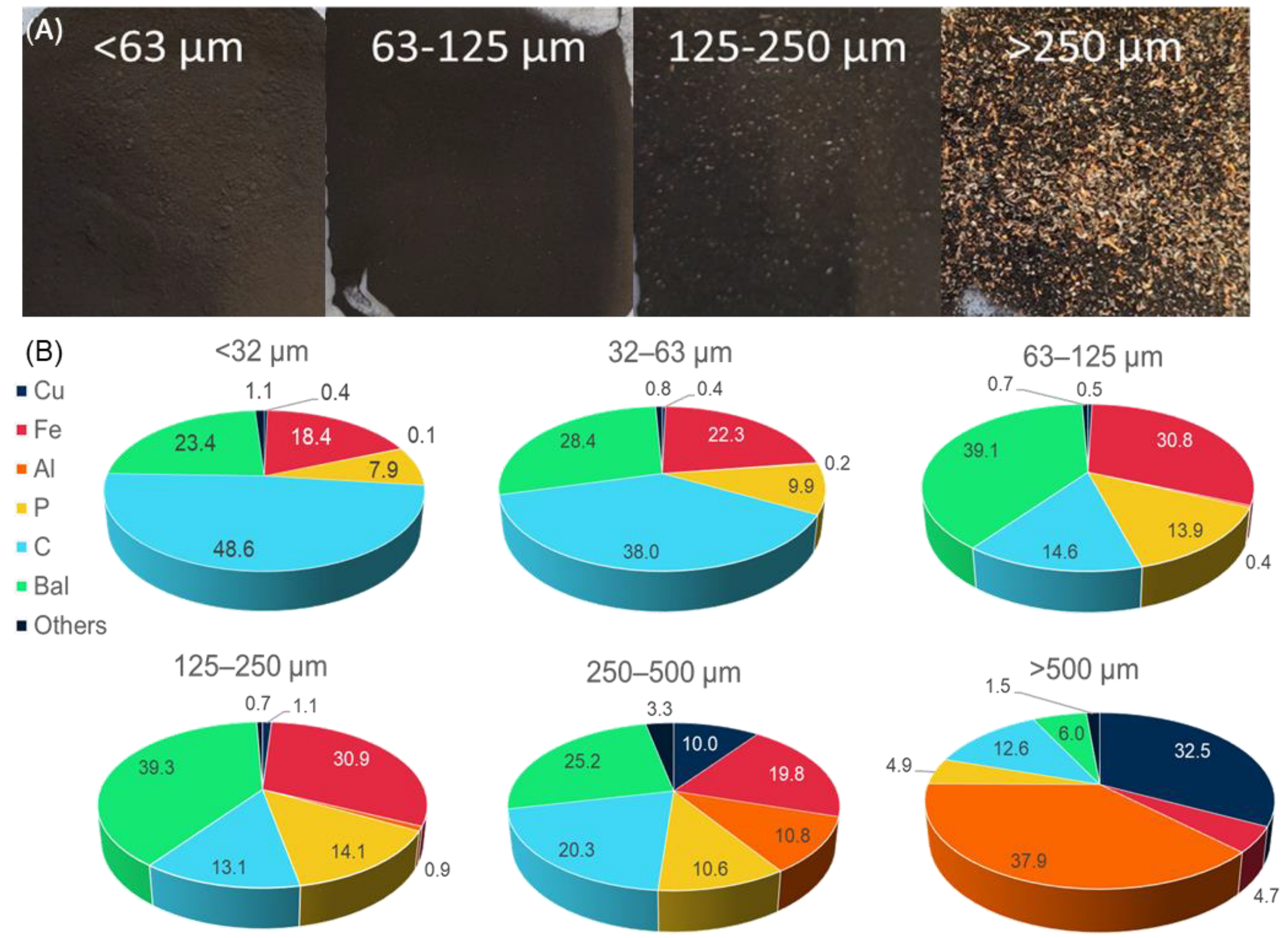
3.2.1. Influence of Chemical Agents

The influence of the frother agent (MIBC) addition was studied in increments and the amounts tested were 0, 7.5, 10, and 20 mg/L. The other parameters were all kept constant and a collector amount of 12.5 mg/L of n-dodecane was chosen based on literature review. As can be noted in Figure 2a, the addition of MIBC has a tremendous influence on the amount of material that can be recovered in the froth. In fact, without any added MIBC, only 18% of the initial mass can be found in the froth. On the contrary, adding 20 mg/L of frother results in 84.30 wt% material being recovered in the foam fraction. In conjecture, the recovery rate of carbon in the froth increases with increasing concentration of MIBC (Figure 2b). However, the amount of iron that ends up in the foam follows suit. It is important to note that, even when no MIBC was used, 13.37 wt% of iron was found in the foam fraction. This is believed to be due to the wide size distribution rage of the LFP particles and the relative ease with which the smaller particles are entrapped in the rising air bubbles. This was later confirmed by PSD and SEM analyses (see Figures S7 and S8). Thus, the amount of MIBC that offers the best compromise for the separation of graphite and LFP is 7.5 mg/L.
Under the condition of 7.5 mg/L of MIBC, the effect of collector dosage on the recovery of cathode and anode material was investigated. As depicted in Figure 2c, the mass fraction of the recovered froth increased from 58.36 wt% to 72.76 wt% as the dosage of collector increased from 0 mg/L to 40 mg/L. Figure 2d shows the recovery of iron and the carbon fraction in the tailings and froth, respectively. In this case it was possible to observe a decrease in recovery of iron in the tailings from 56% to 38% following with the reduction of the mass fraction and the addition of collector. The recovery of carbon-fraction in the froth increased upon increasing collector addition, reaching 91% at 40 mg/L. However, to maximize the economic potential of the process and given the marginal improvements between 20 and 40 mg/L of collector, it was decided to employ 20 mg/L of n-dodecane for further optimization tests.

3.2.2. Pre-Treatment

The effect of pre-treatment processes on the subsequent flotation performance were investigated, in particular the difference between simple agitation and sonication. Figure S1 depicts the SEM image at 500× g magnification of a sample of black mass < 125 µm used for the experiments. It is observed that the anodic material containing carbon (darker colour) is agglomerated with the cathodic material containing iron (lighter colour). This agglomeration can be expected to contribute significantly to the suboptimal separation of the carbon material from the LFP cathode material in previously described experiments. Thus, pre-treatment operations are required to liberate the particles and facilitate detachment. Furthermore, LFP and carbon particles were observed to be mainly agglomerated into larger chunks of the same material. Liberation of the agglomerates into smaller particles could furthermore increase the available surface area of the individual particles and thus increase the flotation of the carbon and sinking of the LFP. The effect of a sonication pre-treatment is tested and analysed.
In Figure S2, the results of the particle size distribution (PSD) analyses performed on all test samples are presented. What can be observed is that sonication has a greater effect on reducing the particle size of the samples compared to agitation alone. In fact, the average size of sonicated samples is 15.2 µm compared to 23.3 µm for agitated samples and the untreated black mass, which has a mean size of 18.4 µm. Furthermore, observing the shape attentively, one can see that the tail present on the right-hand size of the graph is no longer present in the sonicated sample while it is prominent in the stirred ones. Figures S3 and S4 provide detailed particle distributions for agitated and sonicated samples, respectively. The effect of pH on the pre-treatment is more prominently visible in the sonicated samples. In fact, for samples treated at pH 14, the distribution does not differ from that of the untreated black mass. However, for samples at pH 8 and pH 10, there is a leftward shift of the curves, indicating a decrease in particle size.
To better understand the mechanism of sonication, the samples at pH 8 with and without sonication pre-treatment were subjected to flotation. In this case, the froth fraction was collected in three intervals of 1-min each. The froths compositions for the untreated and sonicated samples are presented in Figure S5a,b respectively. In the untreated sample, as the collection time increases, the concentration of LFP in the froth increases, from 21% to 40%. In the case of the sonicated one, the two concentrations remain unchanged over time.

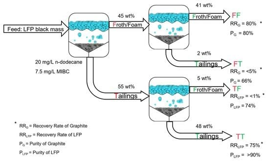
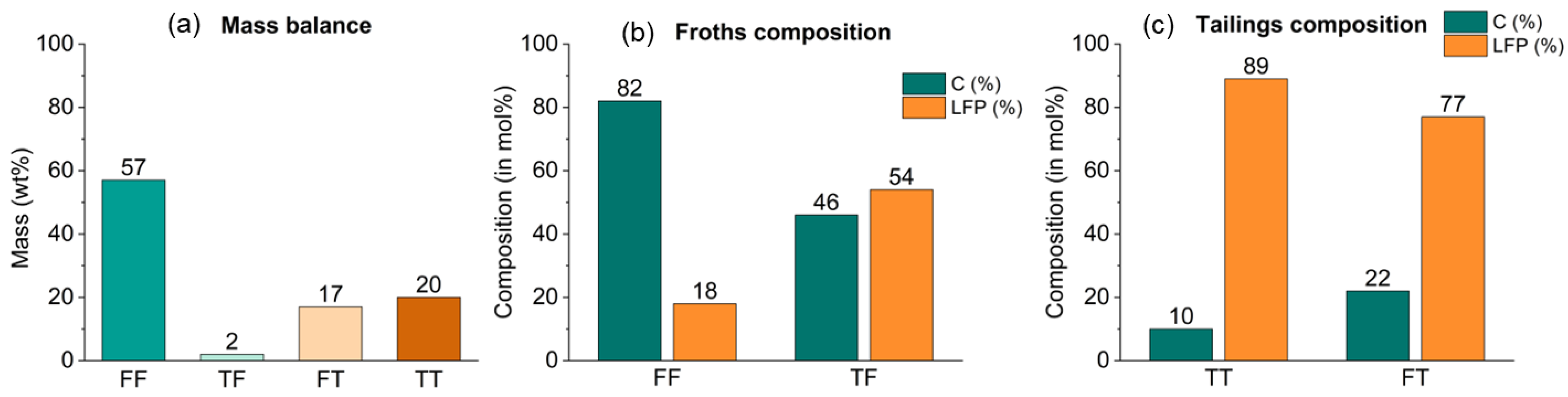
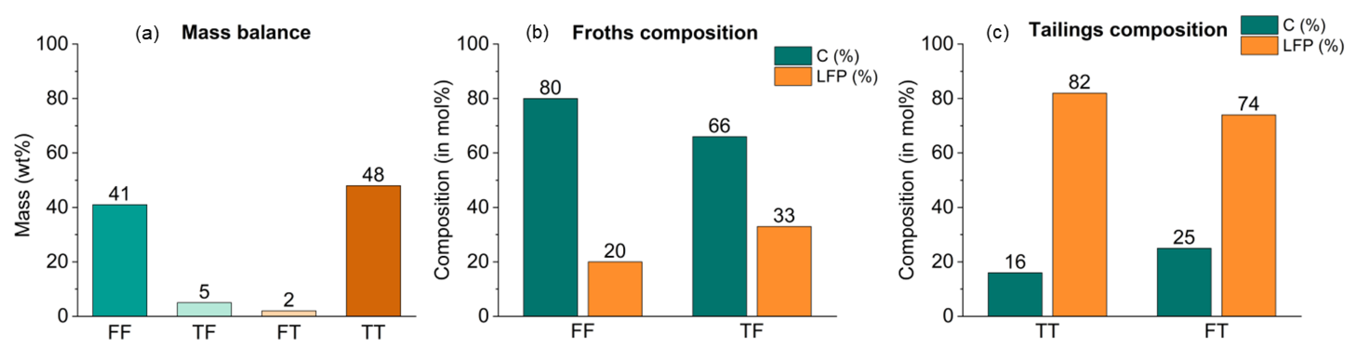
3.2.3. Multi-Step Flotation

The optimized parameters of 7.5 mg/L of MIBC and 20 mg/L of n-dodecane were applied to a multistep flotation process. Herein, the obtained tailings and froth fractions in a first flotation step were subsequently treated by another flotation step. Figure 3a illustrates the mass balance of the multi-step flotation experiment. In comparison to the results obtained with the single flotation process, with the double flotation process, the froth fraction has increased from 67.81 wt% to 73.93 wt% (considering “FF” + “TF”), while the tailings have decreased from 28.57 wt% to 21.58 wt% (considering “FT” + “TT”). The compositions of the four fractions obtained separately and analysed by XRF are depicted in Figure 3b,c. It is important to note that the decreasing amount of tailings is correlated to a higher content of LFP. In fact, a composition of 77.3 mol% and 89.4 mol% of LFP is measured for “FT” and “TT”, respectively. Both concentrations are higher than the amount obtained with a single flotation. A similar trend can be observed for the froth fraction as it presents a concentration of carbon of 82.2 mol%. This contrasts little with the 75.3 mol% obtained for the single process; however, put into perspective of the amount collected, more of the initial carbonaceous material is recovered in a purer form. An important obstacle is posed by the “TF” fraction, composed of 45.5 mol% carbonaceous material and 54.1 mol% LFP.
The difference in composition between the two froth fractions can also be observed in Figure S6, where SEM images of the fractions “FF” and “FT” at magnification 1000× g are overlayed with elemental EDS maps for carbon and iron. It can be noticed that the “FF” fraction is mostly composed of carbon as expected. However, it was observed that LFP particles were still present in the froth layer, partially attached to carbon/graphite particles. Furthermore, as can be observed in the SEM images (Figure S6), the size of the LFP particles present in this fraction is much smaller compared to those of graphite. In the “TF” fraction, on the other hand, the presence of LFP is even higher, as evidenced by a larger amount of lighter particles and Fe in the EDS map. This confirms the XRF analyses. Interestingly, the size of the iron containing particles is larger than in the previous fraction and seem to always be attached to the graphite. In Figure S7, the SEM-EDS images of the “FT” and “TT” fractions are displayed. Confirming the XRF analyses, it is possible to observe the clear predominance of the metal over the carbonaceous portion of the sample for both fractions.

3.2.4. Validation of the Optimized Process

In order to more closely approximate the material output from a battery recycling treatment, samples of black mass with a particle size < 250 µm underwent pre-treatment using sonication followed by a subsequent flotation process. Figure 4a presents the mass balance of the double flotation procedure conducted with this size fraction. It can be observed that the majority of the mass is distributed in the concentrated fractions “FF” and “TT”. Figure 4b,c shows the concentrations of the obtained fractions, revealing a further enrichment of carbonaceous material in both the froth fractions, “FF” and “TF”, with 80 mol% and 66 mol%, respectively, and a high concentration of LFP in the tailings fractions, with 74 mol% and 82 mol%, respectively, in “FT” and “TT”. Figure S8 presents the particle size distribution analyses of the four fractions obtained from flotation, along with the reference black mass < 250 µm and the previously used <125 µm. In this case, it can be observed that the black mass < 250 µm, in addition to a peak around 20 µm, has a second peak at 175 µm, mainly formed by LFP, as deduced from the “TT” curve, which exhibits a peak in close proximity. From Figure S8, it can also be deduced that the flotation separation occurs based on the hydrophobic and hydrophilic properties of the compounds present, but also partly due to gravity, bringing the lighter particles to the surface and the heavier ones to the bottom. The transition from black mass < 125 μm to <250 μm has also led to an increase in impurities that were previously eliminated during the sieving phase. The copper quantity, for instance, has changed from 0.07 wt% in <125 μm to 0.28 wt% in <250 μm. Similarly, aluminium has increased from 0.11 wt% to 1.40 wt%, respectively. Following flotation, these impurities will distribute consistently, as observed with the <125 μm black mass, primarily concentrating in the froth fraction with 0.34 wt% copper and 0.78 wt% aluminium, in contrast to the tailings fraction where they are present at 0.10 wt% and 0.23 wt%, respectively.
The overall recovered LFP, which is the results of the combination of six different experiments using the same optimized flotation parameters, underwent a detailed characterization using powder X-ray diffraction (XRD) and total carbon (TC), ICP, and XRF analyses to precisely determine the mineralogy and composition. From the XRF analysis, we calculated a composition of 13.5 ± 0.2 mol% carbonaceous material and 85.2 ± 0.2 mol% LFP based on the iron content of only the “TT” fraction. Impurities such as copper and aluminium were present at levels of approximately 0.3 mol% and 0.9 mol%, respectively. Powder XRD analysis and Rietveld refinement of the recovered material (Figure 5) revealed that aside from LFP (37.7 mol%) and graphite (7.6 mol%), iron(II) phosphate (Fe2P2O7) (55.3 mol%) was also present, which is a decomposition product of LFP. The TC analysis revealed a total carbon content of 9.40 ± 0.60 wt%. Diffractograms and Rietveld refinement of the individual fractions are available in Figures S9–S12. They confirm the previously obtained results from the XRF but also reveal that the ratio between LiFePO4 and Fe2P2O7 does not vary in the different fractions. The derived carbon percentage is slightly lower than that calculated through XRF.

4. Discussion

To achieve the best possible separation, the number of externally influencing parameters such as impurities should be limited. As can be seen by the results of the sieving experiment, most of the impurities remain contained to the larger sized fractions (above 250 µm). Furthermore, those fractions only represent a minimal amount of the total mass (8.00 wt%).
From the <125 µm fraction, the determination of the ideal conditions for the froth flotation is realized. As observed, the amounts of chemical agents added to the flotation plays a determining role in the efficiency of the separation. Adding too much of the frothing agent proved to be detrimental to the separation of the two active materials. In fact, the creation of too much foam/froth leads to more of the fine particles of LFP to rise with the graphite. This means the separation no longer predominantly operates on the physico-chemical differences but also due to a size factor. For the collector, the threshold to observe this behaviour is much higher. In fact, the collector interacts with the active sites on the surface of the graphite, resulting in an increase hydrophobicity. This means that in this case, the main phenomenon causing some LFP particles to float is the attachment of those particles to the graphite, as can be observed when closely inspecting the SEM images. However, the literature suggest that most LFPs are also coated with a thin layer of carbon, meaning that some of the collector is bound to attach to the surface of some LFP particles as well [54,55,56].
This illustrates the need for separation of the particles in a mechanical treatment before submitting them to the flotation treatment. With the sonication pre-treatment, a greater separation can be observed, and better segregation occurs during the flotation. As observed in the SEM images, the initial sample contains a tremendous amount of agglomerates, whether they are mainly composed of graphite or LFP. Breaking those agglomerates up results in a couple of different benefits; for starters, more surface area of the graphite is exposed and can now interact with the collector. In addition, the LFP particles that were attached on or entrapped in the graphite aggregate are now liberated. In contrast, agitation alone does not enhance the separation. To the contrary, the observed images and results obtained during the time dependent collection experiment suggests that treating the samples with agitation alone, at any pH, promotes greater particle aggregation compared to the untreated black mass. The effect is due to the difference in surface charges between the carbon coated LFP and the graphite. Agitation increases the number of collisions, creating agglomerates.
To improve the separation of the two active materials, multiple flotation steps can be performed. In this case, although the overall mass balances changed very little between the single and double flotation procedure, the grade or purity of the recovered fraction increased remarkably in all but one fractions. In fact, the “TF” fraction displays an almost even distribution of graphite and LFP. The similarly small particle size of graphite and LFP explains the material’s presence in the froth fraction. It is explained by a physical factor known as entrainment rather than a physico-chemical one [57].

5. Conclusions

This study applied froth flotation to a realistic black mass sample obtained by an industrial waste battery recycling process applied to a batch of end-of-life LFP batteries. The influence on the separation efficiency of frother and collector dosage and pre-treatment processes, such as sonication, were investigated and optimized. The addition of MIBC frother agent significantly improved the recovery of material in the froth layer, with a corresponding increase in carbon recovery but also an enhanced iron content was observed in the froth. However, the increasing dosage of n-dodecane as collector improved the recovery of carbon in the froth. Furthermore, sonication of the black mass in water as a pre-treatment step allowed for agglomerates of graphite particles and/or LFP particles to disintegrate, which further improved the separation efficiency.
Finally, multi-step flotation processes were explored, showing that a double flotation procedure resulted in a higher purity of both the obtained carbonaceous and LFP material fractions. However, the “TF” fraction presented a challenge due to its even distribution of graphite and LFP, attributed to entrainment. The optimized process, involving sonication pre-treatment and double flotation in the presence of 7.5 mg/L MIBC and 20 mg/L n-dodecane, led to a significant enrichment of carbonaceous material in the froth fractions and a higher concentration of LFP in the tailings fractions. Detailed characterization of the recovered LFP indicated the presence of iron(II) phosphate (Fe2P2O7) along with LiFePO4 and graphite. In summary, this study demonstrated that a combination of sieving, pre-treatment, and multi-step flotation processes can effectively separate black mass from lithium-ion batteries into relatively pure fractions of carbonaceous material and LFP. The graphite recovery rate was 80% and with a grade of 80%, while the LFP recovery rate was of 75% with a grade > 90%. This research provides valuable insights for the development of efficient and environmentally friendly battery recycling methods.

Supplementary Materials

The following supporting information can be downloaded at: https://www.mdpi.com/article/10.3390/batteries9120589/s1, Table S1: Detailed XRF results of the different fractions obtained after dry-sieving. Figure S1: SEM image taken at magnification X500 of black mass < 125 µm; Figure S2: Particle size distribution analysis of the pretreated samples. SO stands for sonication, ST stands for stirred and the number following depicts the pH value; Figure S3: Particle size distribution of stirred samples: (a) frequency; (b) undersize; Figure S4: Particle size distribution of sonicated samples: (a) frequency; (b) undersize; Figure S5: Composition of the froth collected at regular interval for a) the stirred sample and b) the sonicated sample; Figure S6: SEM images taken at magnification 1000× g of the “FF” fraction (left) and “FT” fraction (right); EDS mapping of C (red), Fe (purple) and Cu (pink) are depicted below; the green box highlights the presence of LFP still partially attached to C/graphite; Figure S7: SEM images taken at magnification 1000× g of the “TF” fraction (left) and “TT” fraction (right); EDS mapping of C (red), Fe (purple) and Cu (pink) are depicted below; Figure S8: Particle size distribution analysis of the black mass fraction < 250 µm compared to the fraction < 125 µm; (a) frequency; (b) undersize; Figure S9: Powder X-ray Diffractogram and Rietveld refinement of the “TT” fraction of the double flotation procedure showing the fractions of LiFePO4, Fe2P2O7 and graphite; Figure S10: Powder X-ray Diffractogram and Rietveld refinement of the “FT” fraction of the double flotation procedure showing the fractions of LiFePO4, Fe2P2O7 and graphite; Figure S11: Powder X-ray Diffractogram and Rietveld refinement of the “TF” fraction of the double flotation procedure showing the fractions of LiFePO4, Fe2P2O7 and graphite; Figure S12: Powder X-ray Diffractogram and Rietveld refinement of the “FF” fraction of the double flotation procedure showing the fractions of LiFePO4, Fe2P2O7 and graphite. Figure S13: Overall flowsheet of the double flotation process with mass balances, recoveries, and grades of the materials in each fraction.

Author Contributions

Conceptualization, J.S.; methodology, O.R., A.P. and J.S.; validation, O.R. and A.P.; formal analysis, A.P. and O.R.; investigation, A.P. and O.R.; data curation, O.R. and A.P.; writing—original draft preparation, O.R.; writing—review and editing, O.R. and J.S.; supervision, J.S.; project administration, J.S.; funding acquisition, J.S. All authors have read and agreed to the published version of the manuscript.

Funding

This research has received funding from the Research Foundation Flanders (FWO) under grant agreement S008621N as part of ERA-NET Cofund on Raw Materials (ERA-MIN3) under the European Union’s Framework Programme for Research and Innovation H2020 in the project ACROBAT—Advance Critical Raw Materials Recycling from Spent LFP Batteries.

Institutional Review Board Statement

Not applicable.

Informed Consent Statement

Not applicable.

Data Availability Statement

Data is contained within the article or Supplementary Materials.

Acknowledgments

The authors wish to thank Nancy Dewit for executing the SEM-EDX analyses.

Conflicts of Interest

The authors declare no conflict of interest. The funders had no role in the design of the study; in the collection, analyses, or interpretation of data; in the writing of the manuscript; or in the decision to publish the results.

References

  1. Global Battery Alliance. A Vision for a Sustainable Battery Value Chain in 2030 Unlocking the Full Potential to Power Sustainable Development and Climate Change Mitigation; World Economic Forum: Geneva, Switzerland, 2019. [Google Scholar]
  2. Han, X.; Ouyang, M.; Lu, L.; Li, J. A comparative study of commercial lithium ion battery cycle life in electric vehicle: Capacity loss estimation. J. Power Sources 2014, 268, 658–669. [Google Scholar] [CrossRef]
  3. Schmuch, R.; Wagner, R.; Hörpel, G.; Placke, T.; Winter, M. Performance and cost of materials for lithium-based rechargeable automotive batteries. Nat. Energy 2018, 3, 267–278. [Google Scholar] [CrossRef]
  4. Padhi, A.K.; Nanjundaswamy, K.S.; Goodenough, J.B. Phospho-olivines as Positive-Electrode Materials for Rechargeable Lithium Batteries. J. Electrochem. Soc. 1997, 144, 1188. [Google Scholar] [CrossRef]
  5. Manthiram, A. A reflection on lithium-ion battery cathode chemistry. Nat. Commun. 2020, 11, 1550. [Google Scholar] [CrossRef]
  6. Georgi-Maschler, T.; Friedrich, B.; Weyhe, R.; Heegn, H.; Rutz, M. Development of a recycling process for Li-ion batteries. J. Power Sources 2012, 207, 173–182. [Google Scholar] [CrossRef]
  7. Zheng, X.; Zhu, Z.; Lin, X.; Zhang, Y.; He, Y.; Cao, H.; Sun, Z. A Mini-Review on Metal Recycling from Spent Lithium Ion Batteries. Engineering 2018, 4, 361–370. [Google Scholar] [CrossRef]
  8. Ciez, R.E.; Whitacre, J.F. Examining different recycling processes for lithium-ion batteries. Nat. Sustain. 2019, 2, 148–156. [Google Scholar] [CrossRef]
  9. Takahashi, M.; Tobishima, S.-i.; Takei, K.; Sakurai, Y. Reaction behavior of LiFePO4 as a cathode material for rechargeable lithium batteries. Solid State Ion. 2002, 148, 283–289. [Google Scholar] [CrossRef]
  10. Forte, F.; Pietrantonio, M.; Pucciarmati, S.; Puzone, M.; Fontana, D. Lithium iron phosphate batteries recycling: An assessment of current status. Crit. Rev. Environ. Sci. Technol. 2021, 51, 2232–2259. [Google Scholar] [CrossRef]
  11. Xu, P.; Yang, Z.; Yu, X.; Holoubek, J.; Gao, H.; Li, M.; Cai, G.; Bloom, I.; Liu, H.; Chen, Y.; et al. Design and Optimization of the Direct Recycling of Spent Li-Ion Battery Cathode Materials. ACS Sustain. Chem. Eng. 2021, 9, 4543–4553. [Google Scholar] [CrossRef]
  12. Wang, Y.; Ma, L.; Xi, X.; Nie, Z.; Zhang, Y.; Wen, X.; Lyu, Z. Regeneration and characterization of LiNi0.8Co0.15Al0.05O2 cathode material from spent power lithium-ion batteries. Waste Manag. 2019, 95, 192–200. [Google Scholar] [CrossRef]
  13. Xu, P.; Dai, Q.; Gao, H.; Liu, H.; Zhang, M.; Li, M.; Chen, Y.; An, K.; Meng, Y.S.; Liu, P. Efficient direct recycling of lithium-ion battery cathodes by targeted healing. Joule 2020, 4, 2609–2626. [Google Scholar] [CrossRef]
  14. Tan, D.H.S.; Xu, P.; Chen, Z. Enabling sustainable critical materials for battery storage through efficient recycling and improved design: A perspective. MRS Energy Sustain. 2020, 7, E27. [Google Scholar] [CrossRef]
  15. Gao, H.; Tran, D.; Chen, Z. Seeking direct cathode regeneration for more efficient lithium-ion battery recycling. Curr. Opin. Electrochem. 2022, 31, 100875. [Google Scholar] [CrossRef]
  16. Chen, J.; Li, Q.; Song, J.; Song, D.; Zhang, L.; Shi, X. Environmentally friendly recycling and effective repairing of cathode powders from spent LiFePO4 batteries. Green Chem. 2016, 18, 2500–2506. [Google Scholar] [CrossRef]
  17. Park, K.; Yu, J.; Coyle, J.; Dai, Q.; Frisco, S.; Zhou, M.; Burrell, A. Direct Cathode Recycling of End-Of-Life Li-Ion Batteries Enabled by Redox Mediation. ACS Sustain. Chem. Eng. 2021, 9, 8214–8221. [Google Scholar] [CrossRef]
  18. Sun, Q.; Li, X.; Zhang, H.; Song, D.; Shi, X.; Song, J.; Li, C.; Zhang, L. Resynthesizing LiFePO4/C materials from the recycled cathode via a green full-solid route. J. Alloys Compd. 2020, 818, 153292. [Google Scholar] [CrossRef]
  19. Tang, X.; Wang, R.; Ren, Y.; Duan, J.; Li, J.; Li, P. Effective regeneration of scrapped LiFePO4 material from spent lithium-ion batteries. J. Mater. Sci. 2020, 55, 13036–13048. [Google Scholar] [CrossRef]
  20. Yang, T.; Lu, Y.; Li, L.; Ge, D.; Yang, H.; Leng, W.; Zhou, H.; Han, X.; Schmidt, N.; Ellis, M.; et al. An Effective Relithiation Process for Recycling Lithium-Ion Battery Cathode Materials. Adv. Sustain. Syst. 2020, 4, 1900088. [Google Scholar] [CrossRef]
  21. Ong, S.P.; Wang, L.; Kang, B.; Ceder, G. Li−Fe−P−O2 Phase Diagram from First Principles Calculations. Chem. Mater. 2008, 20, 1798–1807. [Google Scholar] [CrossRef]
  22. Li, J.; Ma, Z.-F. Past and present of LiFePO4: From fundamental research to industrial applications. Chem 2019, 5, 3–6. [Google Scholar] [CrossRef]
  23. Li, J.; Wang, Y.; Wang, L.; Liu, B.; Zhou, H. A facile recycling and regeneration process for spent LiFePO4 batteries. J. Mater. Sci. Mater. Electron. 2019, 30, 14580–14588. [Google Scholar] [CrossRef]
  24. Li, X.; Zhang, J.; Song, D.; Song, J.; Zhang, L. Direct regeneration of recycled cathode material mixture from scrapped LiFePO4 batteries. J. Power Sources 2017, 345, 78–84. [Google Scholar] [CrossRef]
  25. Liang, Q.; Yue, H.; Wang, S.; Yang, S.; Lam, K.-h.; Hou, X. Recycling and crystal regeneration of commercial used LiFePO4 cathode materials. Electrochim. Acta 2020, 330, 135323. [Google Scholar] [CrossRef]
  26. Jing, Q.; Zhang, J.; Liu, Y.; Zhang, W.; Chen, Y.; Wang, C. Direct Regeneration of Spent LiFePO4 Cathode Material by a Green and Efficient One-Step Hydrothermal Method. ACS Sustain. Chem. Eng. 2020, 8, 17622–17628. [Google Scholar] [CrossRef]
  27. Ma, Z.; Zhuang, Y.; Deng, Y.; Song, X.; Zuo, X.; Xiao, X.; Nan, J. From spent graphite to amorphous sp2+sp3 carbon-coated sp2 graphite for high-performance lithium ion batteries. J. Power Sources 2018, 376, 91–99. [Google Scholar] [CrossRef]
  28. Niu, B.; Xiao, J.; Xu, Z. Advances and challenges in anode graphite recycling from spent lithium-ion batteries. J. Hazard. Mater. 2022, 439, 129678. [Google Scholar] [CrossRef] [PubMed]
  29. Yang, Y.; Song, S.; Lei, S.; Sun, W.; Hou, H.; Jiang, F.; Ji, X.; Zhao, W.; Hu, Y. A process for combination of recycling lithium and regenerating graphite from spent lithium-ion battery. Waste Manag. 2019, 85, 529–537. [Google Scholar] [CrossRef]
  30. Kaya, M. State-of-the-art lithium-ion battery recycling technologies. Circ. Econ. 2022, 1, 100015. [Google Scholar] [CrossRef]
  31. Hossain, R.; Sarkar, M.; Sahajwalla, V. Technological options and design evolution for recycling spent lithium-ion batteries: Impact, challenges, and opportunities. WIREs Energy Environ. 2023, 12, e481. [Google Scholar] [CrossRef]
  32. Pawlik, M. Fundamentals of froth flotation. ChemTexts 2022, 8, 19. [Google Scholar] [CrossRef]
  33. Vanderbruggen, A.; Sygusch, J.; Rudolph, M.; Serna-Guerrero, R. A contribution to understanding the flotation behavior of lithium metal oxides and spheroidized graphite for lithium-ion battery recycling. Colloids Surf. A Physicochem. Eng. Asp. 2021, 626, 127111. [Google Scholar] [CrossRef]
  34. Wang, Y.; Tu, Y.; Xu, Z.; Zhang, X.; Chen, Y.; Yang, E. A promising method for recovery of graphite and cathode materials from spent lithium-ion batteries. Ionics 2022, 28, 2603–2611. [Google Scholar] [CrossRef]
  35. Zhan, R.; Oldenburg, Z.; Pan, L. Recovery of active cathode materials from lithium-ion batteries using froth flotation. Sustain. Mater. Technol. 2018, 17, e00062. [Google Scholar] [CrossRef]
  36. Zhu, Z.; Yin, W.; Wang, D.; Sun, H.; Chen, K.; Yang, B. The role of surface roughness in the wettability and floatability of quartz particles. Appl. Surf. Sci. 2020, 527, 146799. [Google Scholar] [CrossRef]
  37. Wang, D.; Liu, Q. Hydrodynamics of froth flotation and its effects on fine and ultrafine mineral particle flotation: A literature review. Miner. Eng. 2021, 173, 107220. [Google Scholar] [CrossRef]
  38. Brabcová, Z.; Karapantsios, T.; Kostoglou, M.; Basařová, P.; Matis, K. Bubble–particle collision interaction in flotation systems. Colloids Surf. A Physicochem. Eng. Asp. 2015, 473, 95–103. [Google Scholar] [CrossRef]
  39. Zhan, R.; Yang, Z.; Bloom, I.; Pan, L. Significance of a Solid Electrolyte Interphase on Separation of Anode and Cathode Materials from Spent Li-Ion Batteries by Froth Flotation. ACS Sustain. Chem. Eng. 2021, 9, 531–540. [Google Scholar] [CrossRef]
  40. Liu, G.; Yang, X.; Zhong, H. Molecular design of flotation collectors: A recent progress. Adv. Colloid Interface Sci. 2017, 246, 181–195. [Google Scholar] [CrossRef]
  41. Nagaraj, D.R.; Farinato, R.S. Evolution of flotation chemistry and chemicals: A century of innovations and the lingering challenges. Miner. Eng. 2016, 96–97, 2–14. [Google Scholar] [CrossRef]
  42. Zouboulis, A.I.; Matis, K.A.; Stalidis, G.A. Parameters influencing flotation in removal of metal ions. Int. J. Environ. Stud. 1990, 35, 183–196. [Google Scholar] [CrossRef]
  43. Vanderbruggen, A.; Salces, A.; Ferreira, A.; Rudolph, M.; Serna-Guerrero, R. Improving Separation Efficiency in End-of-Life Lithium-Ion Batteries Flotation Using Attrition Pre-Treatment. Minerals 2022, 12, 72. [Google Scholar] [CrossRef]
  44. Wang, C.; Zeng, Y.; Shen, L.; Yang, Y.; Sun, W.; Cao, X.; Tang, H. Enhancement on the selective flotation separation of carbon coated LiFePO4 and graphite electrode materials. Sep. Purif. Technol. 2023, 311, 123252. [Google Scholar] [CrossRef]
  45. Ruismäki, R.; Rinne, T.; Dańczak, A.; Taskinen, P.; Serna-Guerrero, R.; Jokilaakso, A. Integrating flotation and pyrometallurgy for recovering graphite and valuable metals from battery scrap. Metals 2020, 10, 680. [Google Scholar] [CrossRef]
  46. Rinne, T.; Araya-Gómez, N.; Serna-Guerrero, R. A Study on the Effect of Particle Size on Li-Ion Battery Recycling via Flotation and Perspectives on Selective Flocculation. Batteries 2023, 9, 68. [Google Scholar] [CrossRef]
  47. Zhang, G.; He, Y.; Feng, Y.; Wang, H.; Zhu, X. Pyrolysis-ultrasonic-assisted flotation technology for recovering graphite and LiCoO2 from spent lithium-ion batteries. ACS Sustain. Chem. Eng. 2018, 6, 10896–10904. [Google Scholar] [CrossRef]
  48. Zhang, G.; He, Y.; Wang, H.; Feng, Y.; Xie, W.; Zhu, X. Application of mechanical crushing combined with pyrolysis-enhanced flotation technology to recover graphite and LiCoO2 from spent lithium-ion batteries. J. Clean. Prod. 2019, 231, 1418–1427. [Google Scholar] [CrossRef]
  49. Wang, F.; Zhang, T.; He, Y.; Zhao, Y.; Wang, S.; Zhang, G.; Zhang, Y.; Feng, Y. Recovery of valuable materials from spent lithium-ion batteries by mechanical separation and thermal treatment. J. Clean. Prod. 2018, 185, 646–652. [Google Scholar] [CrossRef]
  50. He, Y.; Zhang, T.; Wang, F.; Zhang, G.; Zhang, W.; Wang, J. Recovery of LiCoO2 and graphite from spent lithium-ion batteries by Fenton reagent-assisted flotation. J. Clean. Prod. 2017, 143, 319–325. [Google Scholar] [CrossRef]
  51. Zhu, X.; Zhang, C.; Feng, P.; Yang, X.; Yang, X. A novel pulsated pneumatic separation with variable-diameter structure and its application in the recycling spent lithium-ion batteries. Waste Manag. 2021, 131, 20–30. [Google Scholar] [CrossRef]
  52. Liu, J.; Wang, H.; Hu, T.; Bai, X.; Wang, S.; Xie, W.; Hao, J.; He, Y. Recovery of LiCoO2 and graphite from spent lithium-ion batteries by cryogenic grinding and froth flotation. Miner. Eng. 2020, 148, 106223. [Google Scholar] [CrossRef]
  53. Sun, L.; Qiu, K. Vacuum pyrolysis and hydrometallurgical process for the recovery of valuable metals from spent lithium-ion batteries. J. Hazard. Mater. 2011, 194, 378–384. [Google Scholar] [CrossRef]
  54. Pratheeksha, P.M.; Mohan, E.H.; Sarada, B.V.; Ramakrishna, M.; Hembram, K.; Srinivas, P.V.V.; Daniel, P.J.; Rao, T.N.; Anandan, S. Development of a novel carbon-coating strategy for producing core–shell structured carbon coated LiFePO4 for an improved Li-ion battery performance. Phys. Chem. Chem. Phys. 2017, 19, 175–188. [Google Scholar] [CrossRef]
  55. Raj, H.; Sil, A. Effect of carbon coating on electrochemical performance of LiFePO4 cathode material for Li-ion battery. Ionics 2018, 24, 2543–2553. [Google Scholar] [CrossRef]
  56. Chang, Y.-C.; Peng, C.-T.; Hung, I.-M. Effects of particle size and carbon coating on electrochemical properties of LiFePO4/C prepared by hydrothermal method. J. Mater. Sci. 2014, 49, 6907–6916. [Google Scholar] [CrossRef]
  57. Wang, L.; Peng, Y.; Runge, K. Entrainment in froth flotation: The degree of entrainment and its contributing factors. Powder Technol. 2016, 288, 202–211. [Google Scholar] [CrossRef]
Figure 1. (A) photographs of the different sieving fractions of black mass; (B) Composition of the different sieving fractions determined by XRF, expressed in wt%.
Batteries 09 00589 g001
Figure 2. (a) Influence of the amount of frother (MIBC) on the mass balance of the recovered fractions; (b) Recovery rate of iron and carbon in the different fractions as a function of frother (MIBC) amount; (c) Influence of the amount of collector (n-dodecane) on the mass balance of the recovered fractions; (d) Recovery rate of iron and carbon in the different fractions as a function of collector (n-dodecane) amount.
Batteries 09 00589 g002
Figure 3. (a) mass balance of the different fractions obtained from the multistage flotation process; (b) Composition of the froths obtained from the double flotation process as determined by XRF; (c) Composition of the tailings obtained from the double flotation process as determined by XRF.
Batteries 09 00589 g003
Figure 4. (a) mass balance of the different fractions obtained from the flotation performed on particle size > 250 µm; (b) Composition of the froths obtained from the flotation performed on particle size > 250 µm as determined by XRF; (c) Composition of the tailings obtained from the flotation performed on particle size > 250 µm as determined by XRF.
Batteries 09 00589 g004
Figure 5. Powder X-ray diffractogram and Rietveld refinement of the recovered material.
Batteries 09 00589 g005
Table 1. Parameters of different studies studying froth flotation for LIBs.
Starting MaterialParticle Size (µm)Black Mass Ratio (g/L)Impeller Speed (rpm)Air Flow (L/min)FrotherFrother
(mg/L)
CollectorCollector
(mg/L)
Refs.
Spent LFP-57.11992-MIBC7.5n-Dodecane12.5[44]
Spent LIB500–12504010002MIBC8Kerosene150[45]
LFP/LCO<210101500–1200-MIBC0–12Kerosene30[35]
Spent LCO-40850–10002MIBC8--[46]
Spent LCO<754018002MIBC150n-Dodecane300[47]
LCO-4018002MIBC150n-Dodecane300[48]
Spent LCO<2504018000.8MIBC150n-Dodecane300[49]
Spent LCO<250401800-MIBC150n-Dodecane300[50]
Spent LFP<2504019201.5MIBC150n-Dodecane250[51]
Spent LCO<756016000.7MIBC250n-Dodecane180[52]
Table 2. Chemical composition in wt% of the main constituents of the black mass.
LiAlCuFePCBalance
XRF-0.12 ± 0.010.44 ± 0.0120.50 ± 0.118.16 ± 0.1544.30 a30.03 ± 0.19
ICP2.20 ± 0.010.59 ± 0.111.10 ± 0.4017.00 ± 0.0111.00 ± 0.0142.00 b-
a Carbon concentration estimated based on Balance value obtained by XRF, as explained in the Analyses section. b actual measured total carbon content as described in the Analyses section.
Disclaimer/Publisher’s Note: The statements, opinions and data contained in all publications are solely those of the individual author(s) and contributor(s) and not of MDPI and/or the editor(s). MDPI and/or the editor(s) disclaim responsibility for any injury to people or property resulting from any ideas, methods, instructions or products referred to in the content.

