

Analysis of the Energy Efficiency of a Hybrid Energy Storage System for an Electric Vehicle

1
Automotive Engineering and Transport Department, Technical University of Cluj-Napoca, 400114 Cluj-Napoca, Romania
2
TECOSIM Engineering Srl Cluj-Napoca, 400145 Cluj-Napoca, Romania
*
Author to whom correspondence should be addressed.
Batteries 2023, 9(8), 419; https://doi.org/10.3390/batteries9080419
Submission received: 29 June 2023
/
Revised: 2 August 2023
/
Accepted: 9 August 2023
/
Published: 11 August 2023
(This article belongs to the Special Issue Advances in Hybrid Supercapacitors: Materials, Devices, Models, Systems, and Applications)
Abstract
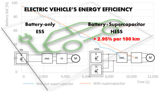
:The large-scale introduction of electric vehicles into traffic has appeared as an immediate necessity to reduce the pollution caused by the transport sector. The major problem of replacing propulsion systems based on internal combustion engines with electric ones is the energy storage capacity of batteries, which defines the autonomy of the electric vehicle. Furthermore, considering the high cost of the battery, it is necessary to consider the implementation of command-and-control systems that extend the life of a battery for as long as possible. The topic covered in this article refers to the analysis by modeling and simulation of the efficiency of a hybrid energy storage system (battery–supercapacitor) adapted for an electric vehicle (e-Golf). Based on the simulations carried out, considering that the operating mode corresponds to the WLTP test cycle, the major conclusion was reached that the use of such a system leads to a decrease in energy consumption by 2.95% per 100 km. Simulations of the model were also carried out to obtain the variation in electricity consumption and vehicle autonomy depending on the number of passengers. Electricity consumption if the vehicle is equipped with a hybrid energy storage system increases by 0.67% on average for each passenger (of 75 kg) added and by 0.73% on average if the vehicle is not equipped with supercapacitors. Moreover, the use of the supercapacitor’s properties leads to the reduction in the peaks in energy taken/given by the battery with a direct effect on extending its life.
1. Introduction
The immediate solution to the global energy crisis and environmental problems caused by the pollutant emissions of internal combustion engine vehicles is considered to be the widespread use of electric vehicles. The main barrier in achieving this is related to the autonomous performance of electric vehicles, performance that is strongly (and directly) affected by the energy storage sources used [1,2]. The immediate requirements of the energy storage systems in electric vehicles are that they must simultaneously offer a pecific energy, a high specific power, and a long lifetime, desires that are difficult to fulfill at the present time with the current sources of energy storage. The usage of a hybrid energy storage system (HESS), which combines an energy storage device with a high power density (such as a supercapacitor), is one of the alternatives suggested and examined for this purpose, together with one with a high density of energy, such as a lithium-ion (Li-ion) battery. Li-ion batteries (among all electrochemical energy storage solutions) are the most used because of their high specific energy, but they have low specific power and a short lifetime, characteristics that limit their application [3]. Compared to Li-ion batteries, supercapacitors have a longer lifetime and higher specific power [4]. As a result, the utilization of an HESS, which combines Li-ion batteries with supercapacitors, benefits from both the Li-ion batteries’ high specific energy and the supercapacitors’ high specific power. Thus, under the specific conditions of their use in electric vehicles, the overloading of Li-ion batteries can be remarkably reduced with the assistance of supercapacitors, and thus the lifetime of the batteries would be significantly extended.
The existence and technological availability on the market of a much more efficient electrical energy storage system is the main obstacle to the development of electric vehicles, which in the future must offer the performance demanded by customers (especially the travel autonomy) at affordable prices. Energy sources must meet a number of conditions to provide high efficiency and good operational characteristics, including high power and energy density, long lifetime, reliability, and maximum efficiency functioning in a wide range of ambient temperatures. Currently, the most used energy storage systems for electric vehicles are those with electrochemical batteries, hydrogen fuel cells, and supercapacitors, but installing and using only one type of energy storage system is energy inefficient. This has led to the need to carry out studies and research in the field to highlight the effects of the hybridization of energy sources from the point of view of increasing the performance of electric vehicles (autonomy, dynamic, and energetic performances).
There has not been as much research in the field of HESSs as carried out for batteries and, mainly, it has been in related to the identification of domains and areas for application, increasing the energy performance of supercapacitors by developing new materials for components, application in the EV structure and analysis of energy performance for different operating situations, control methods and strategies for energy management of hybrid energy storage sources, etc. [5,6]. The obtained results showed the high potential of their implementation and use [7,8,9].
From the point of view of identifying the fields of implementation of hybrid storage sources, it was highlighted that HESS systems lend themselves mainly to applications in the field of photovoltaic energy (PV) and electric vehicles (EV) [10,11], but also in the field of portable electronics and industrial energy management [12]. Studies and research are continually being carried out to increase the performance of supercapacitors by optimizing the materials used in their construction. Pseudocapacitive materials, including metal oxides such as TiO2, MnO2, Mn3O4, V2O5, and NiO in combination with conductive polymers (polythiophene—PTP, polyaniline—PANI, polypyrrole—PPY) were considered to improve energy performance [13,14,15]. Research was also carried out to identify simple and low-cost manufacturing methods of various charge storage materials for high-performance supercapacitors [16,17]. The need to use both the electric energy from the battery and the energy stored in supercapacitors has led to research, development, and optimization of various control methods and strategies integrated into the energy management system [18,19,20,21]. Regarding the effect of using an HESS system with supercapacitors as the energy source of an EV, the studies carried out considered different particular or standardized functional cycles (NEDC, China bus driving cycle—CBDC, FTP) to analyze parameters such as autonomy, SoC, and SoH [10,18,22].
A technical parameter of supercapacitors not to be neglected is the one given by the difference in the optimal range of temperatures in which supercapacitors can be used compared to Li-ion batteries. Research carried out on this issue showed that the performance related to energy storage offers an important advantage in the use of supercapacitors, i.e., the wide range of functional temperatures: −20 ... +80 °C [7,23]. This can be an advantage in the implementation of HESS battery–supercapacitor systems in electric vehicles, the use of supercapacitors outside the functional temperature limits of Li-ion batteries (with +15 ... +35 °C being the optimal functional range considered [24]) being beneficial for increasing the lifespan of energy sources. The wider range of operating temperatures also makes it possible to facilitate the fast-charging process, a process demanded more and more by electric vehicle users [25]. A major benefit is that the management of hybrid HESS systems is compatible with (and may be utilized with) both air and liquid thermal management systems used for energy sources with batteries [26,27]. One additional advantage of using HESS battery–supercapacitor systems for electric vehicles is that the supercapacitor does not pose risks of ignition and burning in the event of a traffic accident in certain constructive configurations (depending on the type of electrolyte: aqueous and inorganic solid, for example) [7].
Because supercapacitors are expensive to purchase, despite all the benefits listed above, the HESS battery–supercapacitor systems have not been widely adopted or used (the price of a supercapacitor with the same energy capacity as a Li-ion battery being 275% higher [28]). However, research carried out in this direction has shown that this problem is a false one if the entire lifetime of the EV is considered, due to the large difference between the life cycles of supercapacitors compared to Li-ion batteries. A comprehensive study was carried out regarding the economic efficiency of the use of hybrid HESS systems (battery–supercapacitor) implemented in the propulsion system of different electric buses [28]. The main results obtained showed that adding a supercapacitor unit to the battery module increased the price of the energy storage system by approximately 25%, but by extending the battery life, it reduced its operating costs by 10 to 27% (compared to the use of a battery-based energy storage unit). Similarly, the use of a hybrid HESS system for a micro-EV showed that the operating costs over the entire lifetime were lower by 3.76 ... 15.88% than the use of a single power battery [29]. Furthermore, the application of an HESS battery–supercapacitor in stationary UPS (uninterruptible power supply) systems showed that the battery’s capacity faded by up to 60% and the amortized cost of the hybrid system was 17.6% less than that of the battery alone [30].
Energy storage is one of the main challenges not only for EV technology but also for the field of renewable energy, due to its intermittent nature. In this study, the focus is on the analysis of the use of hybrid energy storage systems in EVs with the aim of better understanding the immediate advantages and the possibilities of developing new practical concepts which can contribute to solving the energy problems that appear in electric vehicles. The paper presents a study based on computerized numerical analysis (simulation) on the efficiency of hybrid energy storage systems based on the use of supercapacitors in EVs, with the aim of improving the vehicle’s autonomy, protecting the battery from extreme operating demands (peak currents), and thus, extending its life. The novelty of the study is in the fact that it was used to identify the performance of an HESS applied to an EV, the WLTP test cycle (which replaced the old test cycles) and the model were validated based on the data obtained through real testing (and provided by the manufacturers) of an e-Golf vehicle.
2. Current Status of Hybrid Energy Storage Systems (HESSs)
It should be noted that in addition to battery–supercapacitor HESSs (systems that present good functional properties and are used in the construction of several EVs), there are other types of hybrid systems that can be used, such as flywheel, compressed air, and superconducting magnetic energy storage systems. Although these energy storage systems are still in different research phases, they can be further developed and applied in the future to EVs and PHEVs (plug-in hybrid electric vehicles) thanks to the features and characteristics that will be presented in the following sections.
2.1. Hybrid Energy Storage System with Flywheel
Rather than using a battery and supercapacitor HESS, the flywheel system uses a kinetic device. In essence, a flywheel created for energy storage is a rotating disc with a very high moment of inertia that is intended to spin at extremely high rates (20,000–50,000 rpm). Electricity can be created by converting stored kinetic energy into electricity, and vice versa. Typically, the motor (or generator) is connected to the steering wheel, though it can also be the rotor itself. In engine mode, the EV simply increases its speed to increase the kinetic energy stored in the steering wheel, and in generator mode, the flywheel of the electric car drives the shaft mechanically. [31]. The major problem related to this hybrid energy harvesting system is that the high-speed flywheels must be insulated in a vacuum to reduce energy losses due to friction, and the bearings used are of the magnetic type for the same purpose [32]. Another disadvantage in its use is the fact that the flywheels are high-speed devices that require insulating casings of special construction to prevent damage caused in cases of mechanical failure. The advantage of flywheel systems is that they have a long lifetime (typically approx. 20 years [33]) and provide large amounts of energy in a very short time for specific applications for large vehicles (lorries, buses, and locomotives).
Figure 1 shows a hybrid electrical energy storage system that includes a flywheel and a battery. The flywheel can be connected to the DC bus via a bidirectional DC/AC converter and a high-speed electric motor/generator. When the vehicle decelerates, energy is captured by the flywheel by driving the electric car in motor mode and the converter in inverter mode. The electric machine runs in generator mode and the converter is operated in rectifier mode when the energy stored in the flywheel is needed for propulsion [33,34,35].
2.2. Hybrid Energy Storage System with Compressed Air
Hybrid energy storage systems with compressed air may also be future solutions in EV construction. These energy storage options outlast batteries by a significant margin and have an energy efficiency of 75–80% [36]. They feature a reasonably straightforward design and functionality in addition to their high efficiency and long lifespan (Figure 2).
The DC bus can be used to connect compressed-air-based potential energy storage devices by using a motor/generator and a bidirectional DC/AC–AC/DC converter. The converter is used in inverter mode while the electric machine is used in motor mode during the energy storage process. The compressed air tank’s pressure is raised by a pump that the engine powers and functions similarly to a compressor. The converter is operated in rectifier mode and the electric machine is run in generator mode whenever power from the compressed air system is required. In this way, the pneumatic pump is driven by the compressed air that is released from the tank through the valve and drives the electric machine that works in generator mode and provides the necessary energy. The electronic power converter and compressed air tank valve are controlled according to the mode of operation and the amount of power to be delivered to/from the compressed air storage system.
2.3. Superconducting Magnetic Energy Storage Systems
Superconducting magnetic energy storage systems (SMESSs) can store electrical energy in the form of magnetic energy. SMESSs are capable of rapidly transferring large amounts of energy during both charging and discharging with over 95% efficiency [37].
The combination of a battery with SMESS in HESS provides a high power density and high energy density without moving mechanical parts [38,39,40]. SMESSs can replace both batteries and supercapacitors, but the main disadvantage of these systems is that they operate at very low temperatures (electromagnetic coils are used to act as a superconducting material and reduce ohmic losses). For this, the SMESS must be embedded in a cryogenic system whose complexity and refrigeration power reduce the overall efficiency of the system. Cooling can be ensured by evaporating a cryogenic liquid such as helium, nitrogen, or neon [41], but the application of these strategies to vehicles represents a very large limitation of practical applicability. The most practical and cost-effective immediate option is to set up the conditions for the use of high-temperature superconductors, which would enable SMESSs to be used in the construction of electric vehicles. However, high-temperature superconductor material development is still in its infancy [42,43,44]. The possibility of implementing SMESSs in EVs is presented in Figure 3.
2.4. Hybrid Energy Storage System with Supercapacitor
Currently, Li-ion batteries are widely used as energy storage systems in EVs due to their high energy density, operational safety, reliability, and increasingly low production cost. However, the peculiarities of their operation and exploitation make frequent charge–discharge cycles directly affect the life of the batteries [3]. By adding more supercapacitors, which will lower the battery’s maximum current, battery performance can be increased (Figure 4). Supercapacitors have a long lifespan and a high power density of over 6000 W/kg due to the absence of chemical variations at the electrodes; however, the relatively low energy density of 5 Wh/kg [45] prevents the use of supercapacitors as the primary energy sources in an EV.
Both electric and hybrid vehicles, as well as fuel cell vehicles, may benefit from hybrid energy storage systems made up of a battery and a supercapacitor because they have high energy and power utilization and long battery and supercapacitor lifespans [46,47]. A battery can store large amounts of energy (of the order of 100 Wh/kg), but it is not suitable for providing a large amount of energy in a very short time, which is due to a low power density [48]. A supercapacitor has a low storage capacity but can deliver a large amount of power (10 kW/kg) [49]. In a hybrid storage system, the battery is used to provide a large (and relatively constant) amount of energy at low loads, while the supercapacitor is used to meet the demands of regenerative braking and acceleration.
Such a scenario also helps to improve battery life, and the combination of battery and supercapacitor also has the advantage of reducing the size and weight of the energy storage system [50,51].
Although significant progress has been made in recent decades in improving the energy performance of batteries, the main problem comes from how they are used. Battery damage can occur even in small electronic devices such as mobile phones and laptops due to sudden power utilization or demand. This condition is permanent in EVs because a variety of circumstances, including traffic, driving habits, the road, unexpected accelerations, etc., produce quick changes in how the battery is used, resulting in a sharp decline in battery performance and life. Due to this, the optimization of energy storage systems in an EV has become vital and the battery–supercapacitor hybrid storage system is one of the systems that can be used in EVs to increase battery life. By using supercapacitors, batteries are protected from high peak currents, which can be harmful to batteries. Additionally, the battery cannot be regularly depleted at a rate fast enough to fulfill the demands of an EV that suddenly consumes power during acceleration. The storage of a high current produced during braking (if a regenerative braking system is present) follows the same rules. The electrolytes may suffer as a result of these significant electrical current variations to and from the battery. The battery life is shortened when this acceleration–braking cycle is repeated (such as when driving in urban agglomerations).
Supercapacitors are electrochemical systems similar to batteries, but the main difference is that they can charge and discharge very quickly. They are good solutions to meet short-term energy needs but cannot be used as the only energy source in electric vehicles (EVs) due to their lower energy density when compared to batteries.
When a vehicle incorporates a hybrid energy storage system, braking energy is stored in both supercapacitors and batteries. The energy from the supercapacitors can be reused to accelerate the vehicle, and the energy stored in the batteries can be used to serve other systems such as the passenger compartment heating, air conditioning, or other electronic devices in the vehicle. Therefore, the total performance of EVs can be significantly impacted by a well-designed hybrid energy storage system with high energy density, extended lifetime, and high power density. Hybrid energy storage systems are mostly used from an economic point of view, for energy recovery from braking in passenger transport vehicles, such as city e-buses [52].
2.5. Classification of Battery–Supercapacitor Hybrid Energy Storage Systems
A battery–supercapacitor hybrid storage system can have a wide range of topologies, and Figure 5 illustrates some fundamental strategies for combining the two energy storage options [53]. In the simplest configuration (Figure 5a), the power distribution between the parallel-connected energy storage units is simply governed by their internal resistance. The hybrid passive storage system works well as an energy source for starting motors but is ineffective as an energy source for electric vehicles (EVs).
To optimize the merging of supercapacitors and batteries into a single package, DC/DC converters are needed to manage the power flow between them and the DC bus. Figure 5b represents a hybrid active energy storage system. This topology allows power exchange directly between the source and the supercapacitors without the use of a DC/DC converter. The main power flow from the battery is controlled by a DC/DC converter, which allows the power to be split, but at the same time increases losses due to the converter.
Moreover, such a system imposes restrictions on the acceptable voltage values of the supercapacitors. The output voltage must be higher than the BEMF (back electromotive force) of the electric motor (which necessitates the use of high-voltage supercapacitors [30]). In another topology (Figure 5c), a supercapacitor is connected to the battery through the bidirectional DC/DC converter. The DC/DC converter allows for proper load sharing between two devices, as well as controlling the power flow between them to maintain the proper voltage of the supercapacitors. In general, hybrid energy storage systems (battery–supercapacitor) can be classified based on their connections (Figure 6).
The easiest and most affordable topology is the passive connection of the battery and supercapacitor to the DC bus; the battery and supercapacitor are connected to the DC bus at the same voltage (which is determined by the battery’s state of charge value and charge/discharge characteristic). Because of this, EV and PHEV construction typically uses the passive connection.
3. Materials and Methods
3.1. Theoretical Considerations on Supercapacitors
Compared to current battery technologies, supercapacitors have a much lower energy density, with the ability to charge and discharge very quickly, and have a high power density. These technical operating characteristics can improve the autonomy of an EV when the supercapacitors and the battery form an HESS. The selection process of a supercapacitor for integration into an HESS is based on the following parameters: voltage, capacitance, energy storage capacity, and energetic losses. The supercapacitor’s nominal voltage needs to be as close as possible to the EV’s DC bus voltage and satisfy Equation (1) [54]:
The minimum voltage at which a supercapacitor can operate is closely related to the current Ic_max and the power P0 that the DC/DC converter can handle.
The storage capacity of the supercapacitor can be calculated with the relation:
where Vsc_max is the maximum voltage of the supercapacitor, C0 represents the capacitance of the supercapacitor, VsC0 is the initial voltage of the supercapacitor, and Kc is a coefficient that represents the effects of the supercapacitor’s diffusion layer. Equations (4) and (5) provide the initial capacitance C0 for the given coefficient and the braking energy EB, respectively:
with Vsc_int the intermediate voltage of the supercapacitor.
The braking energy EB is given by:
where ηB is the efficiency of the entire conversion system (including the drive converter, motor, DC/DC converter, and supercapacitor efficiency), the power P0(t) is the drive shaft power, and TB is the braking time [55]. The transfer energy (ride-through) ERT available from the supercapacitor is given by Equation (6) and the transfer energy that the supercapacitor package can deliver to the system, when the EV does not accelerate, can be calculated with Equation (7):
where TRT is the transfer time and ηM is the efficiency of the whole system, which depends on the internal resistance of the supercapacitor pack and the power of the drive shaft P0(t).
To protect the supercapacitors, it is not advised to discharge all of their energy during actual operation. As a result, the maximum permitted discharge energy must be established. Equation (9) can be used to compute the depth of discharge (DoD):
When choosing supercapacitors, it is important to calculate the energy losses of the supercapacitors. Assuming that the supercapacitor is a linear capacitor (KC ≅ 0) and neglecting the internal resistance RC0, the charging and discharging currents can be calculated with Equations (9) and (10):
where Vsc_0 is the initial voltage and the charge/discharge power PC0 is constant [56]. The power losses of the supercapacitor are calculated using Equations (11) and (12):
3.2. Modeling and Simulation of the Electric Vehicle
The numerical analysis of the energy efficiency of an HESS for an EV application was carried out by using a numerical model built in the AVL CRUISE software application. The AVL CRUISE application is a complex and dedicated software application for the simulation of different models of propulsion systems for motor vehicles. The initial data, input data, and technical characteristics of the vehicle propulsion system were used to build the numerical model for the simulation process.
For the analysis and study of the theme presented in this article, a virtual EV was built and developed based on the constructive parameters of a Volkswagen (VW) e-Golf electric vehicle. The purpose of the simulations is to highlight the comparative energy performance of the considered energy storage systems (battery system and battery–supercapacitor hybrid system) by analyzing the differences in autonomy and energy consumption. The steps taken to define the computerized simulation process algorithm are the following:
- Creating a new project/version;
- Development of the vehicle model;
- Realization of energy connections;
- Making informational connections;
- Entering the initial technical data into the model;
- Establishing tasks and simulation criteria;
- Establishing the characteristics of the simulation process;
- Running computer simulations;
- Visualization and evaluation of results.
The virtual electric vehicle model of a VW e-Golf was created and developed with the AVL CRUISE software (Figure 7). The constructive data of the vehicle were taken from the technical documentation of the manufacturer.
General information about the electric vehicle’s components (1) is provided in Table 1, including constructive parameters, aerodynamic characteristics, overall dimensions, etc.
The final transmission element (2) is used as a link in the kinematic chain transmission before the differential with the technical data of the considered parameters presented in Table 2.
The wheels (3–6) consider a number of factors and how they affect the running condition (all input data for all vehicle wheels are the same). The data of an e-Golf wheel type 205/55R16 91H can be found in Table 3. Disc brakes (7–10) define the technical characteristics of the braking elements, presented in Table 4.
In the element e-drive or electric motor (11) the general data of the motor are defined (see Table 5), and in Figure 8 the map of the motor moment is presented.
The differential (12) allows the wheels to rotate at different speeds during the turn and the cockpit component (13) makes the connection between the driver and the vehicle, the connections being made through the data bus connection data bus. The traction force transmission factor to the wheels attached to the running gear is represented by the ASC control (14). All electrical consumers of the vehicle’s electrical network are included in the electrical consumers block (15).
The battery component (16) simulates the battery used as a power source for the electric vehicle. The values of the parameters that define the high-voltage Li-ion battery of an e-Golf electric vehicle are presented in Table 6. The battery of the VW e-Golf vehicle is a battery with a 323 V nominal voltage and a weight of 318 kg (represents 21% of the total weight of the unloaded vehicle). The battery is composed of 264 cells of 25 Ah from Panasonic, arranged in 27 modules, having the configuration 88s3p. The technical and functional parameters of a single cell are presented in Table 7.
The drive system (eDrive control system) (17) is a user-defined function used when simulating the ECU (engine control unit) in both engine and generator modes. The brake control system (18) controls the conversion of engine torque to brake pressure. The monitor element (19) monitors selected signals on the data bus connection bus. The constants component (20) allows the definition of constants, which can be used by other components through the data bus.
To carry out the simulations, as well as to exploit the characteristics of the EV, the WLTP test cycle (worldwide harmonized light-duty vehicles test procedure) was considered (Table 8). The WLTP test cycle is a globally harmonized test method for passenger cars and light commercial vehicles and from 1 September 2018, the WLTP testing cycle replaced the new European driving cycle (NEDC). The consumption and CO2 emission values measured according to WLTP are greater than those measured according to NEDC when taking into account the (more) realistic test conditions; for conventional vehicles, a gap of up to 31% was found between the declared and actual fuel consumptions [57].
The validation of the model consists in the comparative analysis of the EV e-Golf’s autonomy following the simulations and the one provided by the manufacturer (Volkswagen GmbH) of 133.6 km for a 100% charge. For the simulation, the limit values of the battery charge level were chosen to be a maximum of 95% and a minimum of 20%, because a battery will never be charged to 100%, and after reaching the charge level of 20%, the energy performance decreases suddenly. In Figure 9, the charge level (state of charge—SoC) of the battery is represented according to the distance traveled, and under the considered conditions, the autonomy given by the manufacturer would be 113.56 km and the value obtained by the simulation was 114.50 km (error of 0.82%), which was considered to validate the numerical model used to analyze further the energy efficiency of an HESS for an EV using a simulation.
For the supercapacitor and the battery to work harmoniously, the nominal voltage of the supercapacitor and the battery must be as close as possible. On this basis, the technical characteristics of the supercapacitor type BMOD0165 produced by the Maxwell company were chosen for use as the input data of the model, and the numerical model of the VW e-Golf electric vehicle equipped with an HESS (battery—supercapacitor) is represented in Figure 10.
In addition to the EV model with a battery, there are two additional constructive elements: the supercapacitor and the DC/DC converter. The supercapacitor (16) is an electrical energy storage device that uses two different mechanisms to store electrical energy and contribute to its total capacity, electrostatic capacitance, based on the electrical double layer, and electrochemical pseudo capacitance. The technical and functional data of the supercapacitor used are presented in Table 9. Since the voltage of the supercapacitor pack must be as close as possible to the battery voltage, the configuration of a module consisting of seven supercapacitors mounted in series was chosen, a configuration that satisfies the requirement of connection with the battery. This results in a total capacitance of 23.57 F and a normal voltage of 340.2 V for the supercapacitor module.
A DC/DC converter (18) should be implemented for voltage and current control. At the same time, the DC/DC converter can also optimize the motor control to avoid the overvoltage phenomenon, and the specific parameters introduced in the numerical model are presented in Table 10.
4. Results
Based on the simulations performed on the validated numerical model, the following section will present the results obtained for the virtual EV based on the constructive and functional characteristics of the VW e-Golf vehicle (with and without HESS). The element considered for the comparative analysis was the driving range in the context of an operating regime based on the WLTP test cycle.
In Figure 11, the battery charge level according to the distance traveled when the vehicle is equipped with a hybrid energy storage system is shown. It can be seen that the battery discharges to 20% after traveling 131.3 km, 14.67 km more than the situation where the vehicle is not equipped with a hybrid energy storage system. This difference represents an increase in autonomy of approximately 15%, and Figure 12 more precisely represents the variation in the battery SoC with time.
Figure 12 represents the variation in the battery charge level when the vehicle is equipped with an HESS (red line), and when the vehicle operates only with the battery (blue line). As can be seen in the graph, if the vehicle is equipped with a hybrid system (with battery–supercapacitor), the discharge of the battery is much smoother, which means less charge–discharge variations, which leads to a longer battery life.
Figure 13 shows the variation in the electric power of the battery when working in tandem with the supercapacitor pack. To be able to better analyze the variation in the electric power of the battery as a function of time, this graph was made using only one WLTP cycle. The Li-ion battery constantly provides energy for the supercapacitor while it powers the electric motor or absorbs energy from braking and as can be seen from the graph, the electric power of the battery is stable and works at about 2.99 kW. In contrast, the electric power of the battery without a supercapacitor varied between −50 and 30 kW with frequent fluctuations, as seen in Figure 14.
There is a clear power fluctuation, and the battery is frequently charged and discharged, which inevitably leads to battery degradation. By using a hybrid energy storage system, these power fluctuations are smoothed out (no sudden peaks) and consequently, battery life is extended.
As seen in Figure 15, the variation in the electrical power of the supercapacitor module is very similar to the variation in the electrical power of the battery when there is no HESS. This can be explained by the fact that by using a hybrid energy storage system, the supercapacitor pack takes over most of the battery’s load, while the battery is only used to provide the energy needed by the supercapacitor pack. The battery’s output energy can be maintained at a constant level with the help of the DC/DC converter, which eliminates significant charge–discharge variations.
Figure 16 represents the variation in the vehicle’s electricity consumption when it is equipped with supercapacitors, and when it is not. The energy consumption is lower if the vehicle is equipped with an HESS and the energy consumption values per 100 km are shown in Figure 17 and Figure 18, respectively.
Based on these values, it was determined that if the vehicle is equipped with supercapacitors, the consumption of electricity decreases by 2.95% per 100 km.
The initial simulations were carried out with only one person on board the vehicle (the driver), weighing 75 kg. Simulations of the model were also carried out to obtain the variation in electricity consumption and vehicle autonomy depending on the number of passengers (with and without an HESS). Figure 19 shows the energy consumption values of the vehicle with and without supercapacitors depending on the number of passengers, and Table 11 calculates the variations in consumption and autonomy depending on the number of passengers. The electricity consumption if the vehicle is equipped with an HESS increases by 0.67% on average for each passenger (of 75 kg) added and by 0.73% on average if the vehicle is not equipped with supercapacitors. From the yield point of autonomy, it decreases by 0.45% on average for each added passenger when the vehicle operates with an HESS and by 0.49% if the vehicle is not equipped with supercapacitors.
Through the statistical analysis of the data in Table 11, there is a strong linear correlation when interpolating the results using statistical analysis. For the energy consumption analysis, R2 is 0.9990 for the case without SC and 0.9989 for the case with SC, and in the case of the autonomy analysis, R2 is 1 for the case without SC and 0.9981 for the case with SC. This shows that the use of an HESS with a supercapacitor does not directly (and negatively) influence the performance of the electric vehicle, managing to minimize the effect of its own weight added to the total weight of the vehicle.
5. Conclusions
Hybrid energy storage systems (HESSs) have been and are being studied and researched through the lens of the fact that they can increase the energy efficiency of an electric vehicle and, therefore, implicitly the most important parameter, the autonomy traveled for a battery charge.
The large-scale application of such systems faces certain problems related to the high cost of supercapacitors, the thermal behavior being different from that of Li-ion battery cells, high dimensions, and weight, etc. These problems require future studies and research to optimize/solve them.
For the application presented in this article, related to the implementation of an HESS (battery–supercapacitor) for an e-Golf electric vehicle, a virtual model (AVL CRUISE) was created based on its technical, functional, and constructive characteristics. The model was validated based on the data presented by the manufacturer and it was further decided to connect the high-voltage Li-ion battery of the electric vehicle (323 V nominal voltage and 24.2 kWh energy capacity) with a supercapacitor module (340.2 V nominal voltage and 23.57 F capacitance). The results obtained showed that the use of an HESS system leads to a decrease in energy consumption, by 2.95% per 100 km (for WLTP cycle conditions). Simulations of the model were also carried out to obtain the variation in electricity consumption and vehicle autonomy depending on the number of passengers. The electricity consumption if the vehicle is equipped with a hybrid energy storage system increases by 0.67% on average for each passenger (of 75 kg) added and by 0.73% on average if the vehicle is not equipped with supercapacitors.
It should be noted that using a supercapacitor reduces the energy peaks needed by the electric propulsion group (or battery) in the case of abrupt accelerations and decelerations, a common occurrence in urban vehicle operation. This fact has been confirmed by various researchers as directly leading to the extension of the effective life of a battery, which has a direct effect on costs and environmental protection.
A new and interesting direction of research is also given by the results obtained through the prism of the fact that the use of HESS battery–supercapacitor manages to increase the energy efficiency of energy sources by minimizing the effect of the weight added to the hybrid energy source (compared to a conventional battery source). This was also confirmed by recent research carried out on this issue investigating the possibilities and opportunities to use HESS systems in the construction of electric propulsion groups of aircraft [59,60].
Author Contributions
Conceptualization, E.A.K. and F.M.; methodology, E.A.K. and F.M.; software, E.A.K.; validation, E.A.K. and F.M; investigation, E.A.K.; writing—original draft preparation, F.M; writing—review and editing, F.M. All authors have read and agreed to the published version of the manuscript.
Funding
This research received no external funding.
Acknowledgments
This work was possible due to support of AVL List GmbH through university program and with support of TUCN internal grant for publishing program.
Conflicts of Interest
The authors declare no conflict of interest.
References
- Sepasi, S.; Ghorbani, R.; Liaw, B.Y. A novel on-board state-of-charge estimation method for aged Li-ion batteries based on model adaptive extended Kalman filter. J. Power Sources 2014, 245, 337–344. [Google Scholar] [CrossRef]
- Sepasi, S.; Roose, L.R.; Matsuura, M.M. Extended Kalman Filter with a fuzzy Method for Accurate Battery Pack State of Charge Estimation. Energies 2015, 8, 5217–5223. [Google Scholar] [CrossRef]
- Siang, F.T.; Chee, W.T. A review of energy sources and energy management system in electric vehicles. Renew. Sustain. Energy Rev. 2013, 20, 82–102. [Google Scholar]
- Şahin, M.E.; Blaabjerg, F.; Sangwongwanich, A. A Comprehensive Review on Supercapacitor Applications and Developments. Energies 2022, 15, 674. [Google Scholar] [CrossRef]
- Horn, M.; MacLeod, J.; Liu, M.; Webb, J.; Motta, N. Supercapacitors: A new source of power for electric cars? Econ. Anal. Policy 2019, 61, 93–103. [Google Scholar] [CrossRef] [Green Version]
- Roy, P.K.S.; Bora Karayaka, H.; Yan, Y.; Alqudah, Y. Investigations into best cost battery-supercapacitor hybrid energy storage system for a utility scale PV array. J. Energy Storage 2019, 22, 50–59. [Google Scholar] [CrossRef]
- He, X.; Zhang, X. A comprehensive review of supercapacitors: Properties, electrodes, electrolytes and thermal management systems based on phase change materials. J. Energy Storage 2022, 56, 106023. [Google Scholar] [CrossRef]
- Huang, S.; Zhu, X.; Sarkar, S.; Zhao, Y. Challenges and opportunities for supercapacitors. APL Mater. 2019, 7, 100901. [Google Scholar] [CrossRef] [Green Version]
- Kim, K.; An, J.; Park, K.; Roh, G.; Chun, K. Analysis of a Supercapacitor/Battery Hybrid Power System for a Bulk Carrier. Appl. Sci. 2019, 9, 1547. [Google Scholar] [CrossRef] [Green Version]
- Vukajlović, N.; Milićević, D.; Dumnić, B.; Popadić, B. Comparative analysis of the supercapacitor influence on lithium battery cycle life in electric vehicle energy storage. J. Energy Storage 2020, 31, 101603. [Google Scholar] [CrossRef]
- Xiao, G.; Chen, Q.; Xiao, P.; Zhang, L.; Rong, Q. Multiobjective Optimization for a Li-Ion Battery and Supercapacitor Hybrid Energy Storage Electric Vehicle. Energies 2022, 15, 2821. [Google Scholar] [CrossRef]
- Muralee Gopi, C.V.V.; Vinodh, R.; Sambasivam, S.; Obaidat, I.M.; Kim, H.-J. Recent progress of advanced energy storage materials for flexible and wearable supercapacitor: From design and development to applications. J. Energy Storage 2020, 27, 101035. [Google Scholar] [CrossRef]
- Thakur, A.K.; Choudhary, R.B. High-performance supercapacitors based on polymeric binary composites of polythiophene (PTP)-titanium dioxide (TiO2). Synth. Met. 2016, 220, 25–33. [Google Scholar] [CrossRef]
- Saravanakumar, B.; Purushothaman, K.K.; Muralidharan, G. Interconnected V2O5 nanoporous network for high-performance supercapacitors. ACS Appl. Mater. Interfaces 2012, 4, 4484–4490. [Google Scholar] [CrossRef]
- Thakur, A.K.; Deshmukh, A.B.; Choudhary, R.B.; Karbhal, I.; Majumder, M.; Shelke, M.V. Facile synthesis and electrochemical evaluation of PANI/CNT/MoS2 ternary composite as an electrode material for high performance supercapacitor. Mater. Sci. Eng. B 2017, 223, 24–34. [Google Scholar] [CrossRef]
- Tantawy, N.S.; El-Taib Heakal, F.; Ahmed, S.Y. Synthesis of worm-like binary metallic active material by electroless deposition approach for high-performance supercapacitor. J. Energy Storage 2020, 31, 101625. [Google Scholar] [CrossRef]
- Xu, L.; Wu, J.; Zhou, W.; Jiang, F.; Xu, J. Binder-free hierarchical porous N-doped graphene directly anchored on carbon fiber cloth for high-performance electrochemical energy storage. J. Energy Storage 2020, 31, 101682. [Google Scholar] [CrossRef]
- Song, Z.; Hofmann, H.; Li, J.; Hou, J.; Han, X.; Ouyang, M. Energy management strategies comparison for electric vehicles with hybrid energy storage system. Appl. Energy 2014, 134, 321–331. [Google Scholar] [CrossRef]
- Hu, J.; Liu, D.; Du, C.; Yan, F.; Lv, C. Intelligent energy management strategy of hybrid energy storage system for electric vehicle based on driving pattern recognition. Energy 2020, 198, 117298. [Google Scholar] [CrossRef]
- Xu, H.; Shen, M. The control of lithium-ion batteries and supercapacitors in hybrid energy storage systems for electric vehicles: A review. Int. J. Energy Res. 2021, 45, 20524–20544. [Google Scholar] [CrossRef]
- Yang, B.; Wang, J.; Zhang, X.; Wang, J.; Shu, H.; Li, S.; He, T.; Lan, C.; Yu, T. Applications of battery/supercapacitor hybrid energy storage systems for electric vehicles using perturbation observer based robust control. J. Power Sources 2020, 448, 227444. [Google Scholar] [CrossRef]
- Kouchachvili, L.; Yaïci, W.; Entchev, E. Hybrid battery/supercapacitor energy storage system for the electric vehicles. J. Power Sources 2018, 374, 237–248. [Google Scholar] [CrossRef]
- Hung, K.; Masarapu, C.; Ko, T.; Wei, B. Wide-temperature range operation supercapacitors from nanostructured activated carbon fabric. J. Power Sources 2009, 193, 944–949. [Google Scholar] [CrossRef]
- Ma, S.; Jiang, M.; Tao, P.; Song, C.; Wu, J.; Wang, J.; Deng, T.; Shang, W. Temperature effect and thermal impact in lithium-ion batteries: A review. Prog. Nat. Sci. Mater. Int. 2018, 28, 653–666. [Google Scholar] [CrossRef]
- Durganjali, C.S.; Chawla, V.; Raghavan, H.; Radhika, S. Design, development, and techno-economic analysis of extreme fast charging topologies using Super Capacitor and Li-Ion Battery combinations. J. Energy Storage 2022, 56, 106140. [Google Scholar] [CrossRef]
- Voicu, I.; Louahlia, H.; Gualous, H.; Gallay, R. Thermal management and forced air-cooling of supercapacitors stack. Appl. Therm. Eng. 2015, 85, 89–99. [Google Scholar] [CrossRef]
- Zhou, W.; Liu, Z.; Chen, W.; Sun, X.; Luo, M.; Zhang, X.; Li, C.; An, Y.; Song, S.; Wang, K.; et al. A Review on Thermal Behaviors and Thermal Management Systems for Supercapacitors. Batteries 2023, 9, 128. [Google Scholar] [CrossRef]
- Wieczorek, M.; Lewandowski, M.; Jefimowski, W. Cost comparison of different configurations of a hybrid energy storage system with battery-only and supercapacitor-only storage in an electric city bus. Bull. Pol. Acad. Sci. Tech. Sci. 2019, 67, 1095–1106. [Google Scholar]
- Qi, J.; Su, M. Analysis of Micro-Electric Vehicle with Super Capacitor/Battery Hybrid Energy Storage System. J. Phys. Conf. Ser. 2023, 2459, 012091. [Google Scholar] [CrossRef]
- Lahyani, A.; Sari, A.; Lahbib, I.; Venet, P. Optimal hybridization and amortized cost study of battery/supercapacitors system under pulsed loads. J. Energy Storage 2016, 6, 222–231. [Google Scholar] [CrossRef]
- Hebner, R.; Beno, J.; Walls, A. Flywheel batteries come around again. IEEE Spectr. 2002, 39, 46–51. [Google Scholar] [CrossRef] [Green Version]
- Zhang, J.W.; Wang, Y.H.; Liu, G.C.; Tian, G.Z. A review of control strategies for flywheel energy storage system and a case study with matrix converter. Energy Rep. 2022, 8, 3948–3963. [Google Scholar] [CrossRef]
- Jaafar, A.; Akli, C.R.; Sareni, B.; Roboam, X.; Jeunesse, A. Sizing and energy management of a hybrid locomotive based on flywheel and accumulators. IEEE Trans. Veh. Technol. 2009, 58, 3947–3958. [Google Scholar] [CrossRef] [Green Version]
- Talebi, S.; Nikbakhtian, B.; Toliyat, H. A novel algorithm for designing the PID controllers of high-speed flywheels for traction applications. In Proceedings of the Vehicle Power and Propulsion Conference (VPPC), Arlington, TX, USA, 9–12 September 2007; pp. 574–579. [Google Scholar]
- Shen, S.; Veldpaus, F.E. Analysis and control of a flywheel hybrid vehicular powertrain. IEEE Trans. Control Syst. 2004, 12, 645–660. [Google Scholar] [CrossRef]
- Lemofouet, S.; Rufer, A. A hybrid energy storage system based on compressed air and supercapacitors with maximum efficiency point tracking (MEPT). IEEE Trans. Ind. Electron. 2006, 53, 1105–1115. [Google Scholar] [CrossRef]
- Ribeiro, P.F.; Johnson, B.K.; Crow, M.L.; Arsoy, A.; Liu, Y. Energy storage systems for advanced power applications. Proc. IEEE 2001, 89, 1744–1756. [Google Scholar] [CrossRef]
- Ali, M.H.; Wu, B.; Dougal, R.A. An overview of SMES applications in power and energy systems. IEEE Trans. Sustain. Energy 2010, 1, 38–47. [Google Scholar] [CrossRef]
- Ise, T.; Kita, M.; Taguchi, A. A hybrid energy storage with a SMES and secondary battery. IEEE Trans. Appl. Supercond. 2005, 15, 1915–1918. [Google Scholar] [CrossRef]
- Zhang, H.; Ren, J.; Zhong, Y.; Chen, J. Design and test of controller in power conditioning system for superconducting magnetic energy storage. In Proceedings of the International Conference on Power Electronics (ICPE), Daegu, Republic of Korea, 22–26 October 2007; pp. 966–972. [Google Scholar]
- Trevisani, L.; Morandi, A.; Negrini, F.; Ribani, P.L.; Fabbri, M. Cryogenic fuel-cooled SMES for hybrid vehicle application. IEEE Trans. Appl. Supercond. 2009, 19, 2008–2011. [Google Scholar] [CrossRef]
- Mukherjee, P.; Rao, V.V. Superconducting magnetic energy storage for stabilizing grid integrated with wind power generation systems. J. Mod. Power Syst. Clean Energy 2019, 7, 400–411. [Google Scholar] [CrossRef] [Green Version]
- Boicea, V.A. Energy storage technologies: The past and the present. Proc. IEEE 2014, 102, 1777–1794. [Google Scholar] [CrossRef]
- Malozemoff, A.P.; Maguire, J.; Gamble, B.; Kalsi, S. Power applications of high-temperature superconductors: Status and perspective. IEEE Trans. Appl. Supercond. 2002, 12, 778–781. [Google Scholar] [CrossRef]
- Maxwell Technologies. 160 Volt Module. Available online: https://maxwell.com/products/ultracapacitors/160v-module/ (accessed on 22 April 2023).
- Ostadi, A.; Kazerani, M. A comparative analysis of optimal sizing of battery-only, ultracapacitor-only, and battery–ultracapacitor hybrid energy storage systems for a city bus. IEEE Trans. Veh. Technol. 2015, 64, 4449–4460. [Google Scholar] [CrossRef]
- Zhang, C.; Min, H.; Yu, Y.; Wang, D.; Luke, J.; Opila, D.; Saxena, S. Using CPE function to size capacitor storage for electric vehicles and quantifying battery degradation during different driving cycles. Energies 2016, 9, 903. [Google Scholar] [CrossRef] [Green Version]
- Chong, L.W.; Wong, Y.W.; Rajkumar, R.K.; Isa, D. An adaptive learning control strategy for standalone PV system with battery supercapacitor hybrid energy storage system. J. Power Sources 2018, 394, 35–49. [Google Scholar] [CrossRef]
- Rimpas, D.; Kaminaris, S.D.; Aldarraji, I.; Piromalis, D.; Vokas, G.; Papageorgas, P.G.; Tsaramirsis, G. Energy management and storage systems on electric vehicles: A comprehensive review. Mater. Today Proc. 2022, 61, 813–819. [Google Scholar] [CrossRef]
- Yan, X.; Patterson, D. Improvement of drive range, acceleration and deceleration performances in an electric vehicle propulsion system. In Proceedings of the 30th Annual IEEE Power Electronics Specialists Conference, Charleston, SC, USA, 1 July 1999; Volume 2, pp. 638–643. [Google Scholar]
- Chau, K.; Wong, Y. Hybridization of energy sources in electric vehicles. Energy Convers. Manag. 2001, 42, 1059–1069. [Google Scholar] [CrossRef]
- Miller, J.R. Engineering electrochemical capacitor applications. J. Power Sources 2016, 326, 726–735. [Google Scholar] [CrossRef]
- Song, Z.; Hofmann, H.; Li, J.; Han, X.; Zhang, X.; Ouyang, M. A comparison study of different semi active hybrid energy storage system topologies for electric vehicles. J. Power Sources 2015, 274, 400411. [Google Scholar] [CrossRef]
- Seaman, A.; Dao, T.S.; McPhee, J. A survey of mathematics-based equivalent-circuit and electrochemical battery models for hybrid and electric vehicle simulation. J. Power Sources 2014, 256, 410–423. [Google Scholar] [CrossRef] [Green Version]
- Li, Y.; Yang, D.; Ruan, X. A systematic method for generating multiple-input dc/dc converters. In Proceedings of the Vehicle Power and Propulsion Conference, Harbin, China, 3–5 September 2008; pp. 1–6. [Google Scholar]
- Dixon, J.W.; Ortuzar, M.E. Battery, Ultracapacitor, Fuel Cell, and Hybrid Energy Storage Systems for Electric, Hybrid Electric, Fuel Cell, and Plug-In Hybrid Electric Vehicles: State of the Art. IEEE Trans. Veh. Technol. 2010, 59, 2806–2814. [Google Scholar]
- Sibiceanu, A.R.; Iorga, A.; Nicolae, V.; Ivan, F. Consideration on the Implications of the WLTC (Worldwide Harmonized Light-Duty Test Cycle) for a Middle-Class Car, CONAT Brașov; Transilvania University Press: Braşov, Romania, 2016; pp. 203–211. ISSN 2069-0401. [Google Scholar]
- EUROCOC. WLTP Cycle Replaces NEDC. Available online: https://www.eurococ.eu/en/blog/wltp-cycle-replaces-nedc/ (accessed on 22 April 2023).
- Russo, A.; Cavallo, A. Stability and Control for Buck–Boost Converter for Aeronautic Power Management. Energies 2023, 16, 988. [Google Scholar] [CrossRef]
- Russo, A.; Cavallo, A. Supercapacitor stability and control for More Electric Aircraft application. In Proceedings of the 2020 European Control Conference, ECC 2020, Saint Petersburg, Russia, 12–15 May 2020; IEEE: Piscataway, NJ, USA, 2020; pp. 1909–1914. [Google Scholar]
Figure 1.
Hybrid energy storage system with flywheel (B—battery, SC—supercapacitor, CS—control system, PS—powertrain system, FwS—flywheel system, M—motor, M/G—motor/generator, INV—inverter).
Figure 1.
Hybrid energy storage system with flywheel (B—battery, SC—supercapacitor, CS—control system, PS—powertrain system, FwS—flywheel system, M—motor, M/G—motor/generator, INV—inverter).

Figure 2.
Hybrid energy storage system with compressed air (B—battery, SC—supercapacitor, CS—control system, PS—powertrain system, INV—inverter, PnS—pneumatic system, M—motor, M/G–motor/generator, 1—filter, 2—air dryer, 3—pump, 4—valve, 5—air reservoir).
Figure 2.
Hybrid energy storage system with compressed air (B—battery, SC—supercapacitor, CS—control system, PS—powertrain system, INV—inverter, PnS—pneumatic system, M—motor, M/G–motor/generator, 1—filter, 2—air dryer, 3—pump, 4—valve, 5—air reservoir).

Figure 3.
Hybrid energy storage system with SMESS (B—battery, SC—supercapacitor, CS—control system, PS—powertrain system, M—motor, D1 and D2—diodes, S1 and S2—switches).
Figure 3.
Hybrid energy storage system with SMESS (B—battery, SC—supercapacitor, CS—control system, PS—powertrain system, M—motor, D1 and D2—diodes, S1 and S2—switches).

Figure 4.
Hybrid energy storage system (battery + supercapacitor) application in EVs (B—battery, SC—supercapacitor, EMS—energy management system, PS—powertrain system, M—motor).
Figure 4.
Hybrid energy storage system (battery + supercapacitor) application in EVs (B—battery, SC—supercapacitor, EMS—energy management system, PS—powertrain system, M—motor).

Figure 5.
Hybrid energy storage systems (HESS): (a) passive, (b) active with low-voltage battery and high-voltage supercapacitors, (c) active with low-voltage supercapacitor and high-voltage battery.
Figure 5.
Hybrid energy storage systems (HESS): (a) passive, (b) active with low-voltage battery and high-voltage supercapacitors, (c) active with low-voltage supercapacitor and high-voltage battery.

Figure 6.
Classification of hybrid energy storage systems with battery and supercapacitors (HESS) (adapted from [22]).
Figure 6.
Classification of hybrid energy storage systems with battery and supercapacitors (HESS) (adapted from [22]).

Figure 7.
Virtual model of e-Golf electric vehicle without supercapacitor (1: electric vehicle, 2: final transmission, 3: left rear vehicle wheel, 4: left front vehicle wheel, 5: right rear vehicle wheel, 6: right front vehicle wheel, 7: disc brake rear left wheel, 8: disc brake front left wheel, 9: disc brake rear right wheel, 10: disc brake front right wheel, 11: electric motor, 12: differential, 13: passenger, 14: ASC control (anti-slip control), 15: electric consumers, 16: high-voltage electric battery, 17: drive system, 18: braking control system, 19: process monitoring block, 20: model constants).

Figure 8.
Electric motor torque map.

Figure 9.
The simulated autonomy of the e-Golf vehicle.

Figure 10.
The virtual model of the e-Golf vehicle with a hybrid energy storage system (16—supercapacitor, 18—the DC/DC converter).
Figure 10.
The virtual model of the e-Golf vehicle with a hybrid energy storage system (16—supercapacitor, 18—the DC/DC converter).

Figure 11.
Vehicle autonomy with hybrid energy storage system.

Figure 12.
Battery charge level variation with and without supercapacitor.

Figure 13.
The electric power of the battery with a supercapacitor.

Figure 14.
Battery electric power without a supercapacitor.

Figure 15.
The electrical power of the supercapacitor pack.

Figure 16.
Electricity consumption as function of time.

Figure 17.
Power consumption with SC.

Figure 18.
Power consumption without SC.

Figure 19.
Electricity consumption depends on the number of passengers. (a) With supercapacitor; (b) without supercapacitor.
Figure 19.
Electricity consumption depends on the number of passengers. (a) With supercapacitor; (b) without supercapacitor.


Table 1.
Electric vehicle’s component data.
| Parameter | Value | Unit |
|---|---|---|
| Wheelbase | 2629 | mm |
| Curb weight | 1615 | kg |
| Total weight | 2000 | kg |
| Frontal area | 2.5 | m2 |
Table 2.
Final transmission component data.
| Parameter | Value | Unit |
|---|---|---|
| Transmission ratio | 6.058 | - |
| Input moment of inertia | 0.010 | kg∙m2 |
| Output moment of inertia | 0.015 | kg∙m2 |
| Efficiency | 96 | % |
Table 3.
Vehicle’s wheel component data.
| Parameter | Value | Unit |
|---|---|---|
| Moment of inertia | 0.1431 | kg∙m2 |
| Tire friction coefficient | 1 | - |
| Load on wheel | 4037.5 | N |
| Static rolling radius/circumference | 306.055/1923 | mm |
| Dynamic rolling radius/circumference | 308.283/1937 | mm |
Table 4.
Brake component data.
| Parameter | Value | Unit |
|---|---|---|
| Brake piston surface | 1800 | mm2 |
| Friction coefficient | 0.25 | - |
| Specific brake factor | 1 | - |
| Efficiency | 99 | % |
| Moment of inertia | 0.02 | kg∙m2 |
Table 5.
Electric motor component data.
| Parameter | Value | Unit |
|---|---|---|
| Type | PSM | - |
| Nominal voltage | 323 | V |
| Moment of inertia | 1.0 × 10⁻⁴ | kg∙m2 |
| Maximum speed (engine) | 12,000 | 1/min |
| Maximum power (engine) | 85 | kW |
| Maximum torque (engine) | 270 | Nm |
| Maximum speed (generator) | 7000 | 1/min |
| Maximum power (generator) | 84 | kW |
| Maximum torque (generator) | 264 | Nm |
| Efficiency | 92.5 | % |
| Initial temperature | 20 | °C |
Table 6.
General parameters of e-Golf high-voltage Li-ion battery.
| Parameter | Value | Unit |
|---|---|---|
| Maximum charge | 75 | Ah |
| Nominal voltage | 323 | V |
| Energy capacity | 24.2 | kWh |
| Maximum voltage | 339 | V |
| Minimum voltage | 308 | V |
| Initial SoC | 95 | % |
| Number of cell/rows | 88 | - |
| Number of rows | 3 | - |
| Internal resistance (charging/discharging) | 0.001 | Ω |
| Operating temperature | 33 | °C |
| Specific heat transition | 0.4 | W/K |
| Specific heat capacity | 795 | J/kg∙K |
| Total weight | 318 | kg |
Table 7.
Parameters of a single cell.
| Parameter | Value | Unit |
|---|---|---|
| Maximum charge | 25 | Ah |
| Nominal voltage | 3.667 | V |
| Maximum voltage | 4.2 | V |
| Minimum voltage | 3.2 | V |
| Weight | 0.724 | kg |
Table 8.
Parameters for the WLTP test cycle [58].
Table 8.
Parameters for the WLTP test cycle [58].
| Parameter | Value | Unit |
|---|---|---|
| Time | 1800 | sec |
| Distance | 23.27 | km |
| Average speed | 46.5 | km/h |
| Maximum speed | 131.3 | km/h |
| Stationary time | 12.6 | % |
| Constant functioning | 3.7 | % |
| Acceleration | 43.8 | % |
| Deceleration | 39.9 | % |
| Average positive acceleration | 0.41 | m/s2 |
| Maximum positive acceleration | 1.67 | m/s2 |
| Average deceleration | −0.45 | m/s2 |
| Minimum deceleration | −1.50 | m/s2 |
Table 9.
Maxwell BMOD0165 supercapacitor data.
| Parameter | Value | Unit |
|---|---|---|
| Capacitance | 165 | F |
| Nominal voltage | 48.6 | V |
| Maximum current | 1970 | A |
| Maximum voltage | 51 | V |
| Minimum voltage | 46 | V |
Table 10.
DC/DC converter component data.
| Parameter | Value | Unit |
|---|---|---|
| Maximum power | 2 | kW |
| Nominal voltage | 336.6 | V |
| Maximum voltage | 367.2 | V |
| Minimum voltage | 255 | V |
Table 11.
Variations in energy consumption and autonomy depending on the number of passengers.
| Number of Passengers | Energy Consumption (kWh) | Autonomy (km) | ||||||
|---|---|---|---|---|---|---|---|---|
| With SC * | % | Without SC | % | With SC | % | Without SC | % | |
| 1 | 15.5409 | - | 16.0140 | - | 131.310 | - | 114.504 | - |
| 2 | 15.6587 | +0.75 | 16.1453 | +0.81 | 130.719 | −0.45 s | 113.859 | −0.56 |
| 3 | 15.7624 | +1.43 | 16.2567 | +1.52 | 130.128 | −0.90 | 113.352 | −1.00 |
| 4 | 15.8668 | +2.09 | 16.3753 | +2.26 | 129.542 | −1.34 | 112.758 | −1.52 |
* SC—supercapacitor.
Disclaimer/Publisher’s Note: The statements, opinions and data contained in all publications are solely those of the individual author(s) and contributor(s) and not of MDPI and/or the editor(s). MDPI and/or the editor(s) disclaim responsibility for any injury to people or property resulting from any ideas, methods, instructions or products referred to in the content. |
© 2023 by the authors. Licensee MDPI, Basel, Switzerland. This article is an open access article distributed under the terms and conditions of the Creative Commons Attribution (CC BY) license (https://creativecommons.org/licenses/by/4.0/).
Share and Cite
MDPI and ACS Style
Mariasiu, F.; Kelemen, E.A. Analysis of the Energy Efficiency of a Hybrid Energy Storage System for an Electric Vehicle. Batteries 2023, 9, 419. https://doi.org/10.3390/batteries9080419
AMA Style
Mariasiu F, Kelemen EA. Analysis of the Energy Efficiency of a Hybrid Energy Storage System for an Electric Vehicle. Batteries. 2023; 9(8):419. https://doi.org/10.3390/batteries9080419
Chicago/Turabian StyleMariasiu, Florin, and Edmond A. Kelemen. 2023. "Analysis of the Energy Efficiency of a Hybrid Energy Storage System for an Electric Vehicle" Batteries 9, no. 8: 419. https://doi.org/10.3390/batteries9080419
Note that from the first issue of 2016, this journal uses article numbers instead of page numbers. See further details here.