
Multifunctional Multilayer Nanospheres for Ion Regulation in Lithium Metal Batteries
by
 and
and
Yan Li
†,
Manjie Xiao
†,
Chunli Shen
,
Haoqing Ma
,
Lianmeng Cui
,
Wei Yang
,
Tianhao Zhao
,
Yan Zhao
* and
Xu Xu
* State Key Laboratory of Advanced Technology for Materials Synthesis and Processing, International School of Materials Science and Engineering, Wuhan University of Technology, Wuhan 430070, China
*
Authors to whom correspondence should be addressed.
†
These authors contributed equally to this work.
Batteries 2023, 9(3), 149; https://doi.org/10.3390/batteries9030149
Submission received: 31 December 2022
/
Revised: 6 February 2023
/
Accepted: 24 February 2023
/
Published: 26 February 2023
(This article belongs to the Special Issue Advanced Electrolytes for Metal Ion Batteries)
Abstract
:Lithium metal anodes have the potential to break through the theoretical energy density bottleneck of commercial lithium ion batteries. However, the solid-electrolyte interphase (SEI) layer generated from the decomposition of traditional lithium metal electrolytes is destroyed during the lithium metal expansion process, resulting in the growth of lithium dendrites and the formation of dead lithium. In this work, multilayer Fe3O4@Al(OH)3@ZnO (FAZ) nanospheres are prepared using a hydrothermal method to modify lithium metal anodes. An SEI layer rich in LiF can be formed in fluorine-poor electrolytes. The battery assembled using FAZ nanospheres remains stable for 100 cycles with Coulombic efficiency up to 98.6%. A battery paired with a LiFePO4 cathode (18.3 mg/cm2) can perform 100 cycles with a capacity retention rate of 87%. This work provides a simple and practical solution for low-fluoride lithium metal battery technology.
1. Introduction
Due to the non-renewable characteristics of fossil energy and the damage to the environment and climate, human beings urgently need to develop a new generation of energy storage to meet the current demand for energy [1,2,3]. Lithium ion batteries are gradually being more widely used against such a background. However, with the development of human society, the shortcomings of low theoretical energy density and high cost of lithium ion batteries have limited the further development of electric vehicles [4,5,6]. Therefore, scientists chose to focus on the research on a lithium metal battery with higher theoretical energy density. The entry of the lithium metal anode has enough potential to break through the bottleneck of the theoretical energy density of commercial lithium ion batteries and meet the demand of a higher energy density lithium battery due to the rapid development of portable equipment and electric vehicle batteries [7,8,9,10]. However, the SEI layer generated from the decomposition of traditional lithium metal anode electrolytes is damaged during the expansion of lithium metal, which will not only lead to the continuous generation of new SEI layers, consume the lithium anode and electrolyte, but also lead to the lithium dendrite growth and dead lithium formation. These results, together with low Coulombic efficiency and safety problems, greatly limit the commercial application of lithium metal anode [11].
In recent years, the characterization of LiF, the key component of the SEI layer, and the research on its formation and mechanism of action have prompted researchers all over the world to design the electrolyte of lithium metal batteries using multifunctional electrolyte additives, solvent modification, lithium salt combination and high salt concentration optimization to build a stable SEI layer rich in LiF on the surface of lithium metal anodes [12,13,14,15,16,17,18,19,20,21,22,23,24,25]. The improvement of the lithium metal anode by a series of perfluorinated electrolytes (PFE) [26,27,28,29], high concentration electrolytes (HCE) [30,31,32] and local high concentration electrolytes (LHCE) [33,34,35,36,37,38,39,40] has enabled the lithium metal battery to achieve a Coulombic efficiency of higher than 99% and the advantage of stability under high voltage, which has aroused the pursuit of the scientific community. However, the high fluoride content required by these methods, which actually increases the cost burden of lithium metal batteries, and the impact of high-fluoride electrolytes on the environment has been discouraging to scientists. Consequently, how to reduce or even eliminate high-fluoride electrolytes, but still be able to build an SEI layer rich in LiF, has become the optimal solution for lithium metal batteries.
Herein, multifunctional, multilayer Fe3O4@Al(OH)3@ZnO (FAZ)nanospheres prepared by hydrothermal synthesis is used to modify the lithium metal anode. The inner layer of Fe3O4 can assist the nanospheres to load uniformly on the surface of copper foil and inhibit the directional deposition of lithium ions [41]. The middle layer of Al(OH)3 has a strong adsorption effect on F− in the electrolyte and can provide the electrolyte with high fluorine concentration during the growth of the lithium metal, so that the surface of the lithium metal can grow into a SEI layer rich in LiF [42]. The outermost ZnO layer can provide nucleation sites for lithium ions due to its lithiophilic property, avoiding the local high-current-induced lithium dendrite deposition. The battery assembled by using the FAZ nanosphere remains stable for 1000 h and achieves a high Coulombic efficiency of 98.6% over 100 cycles. The battery paired with a LiFePO4 loading cathode (18.3 mg/cm2) can cycle 100 times and the capacity retention rate is 87%. We hope that the multifunctional multilayer nanospheres can create a new method for the research of low-fluoride lithium metal batteries by regulating the movement of ions inside lithium metal batteries.
2. Results and Discussion
2.1. Morphology and Structure Characterization of Various Nanospheres
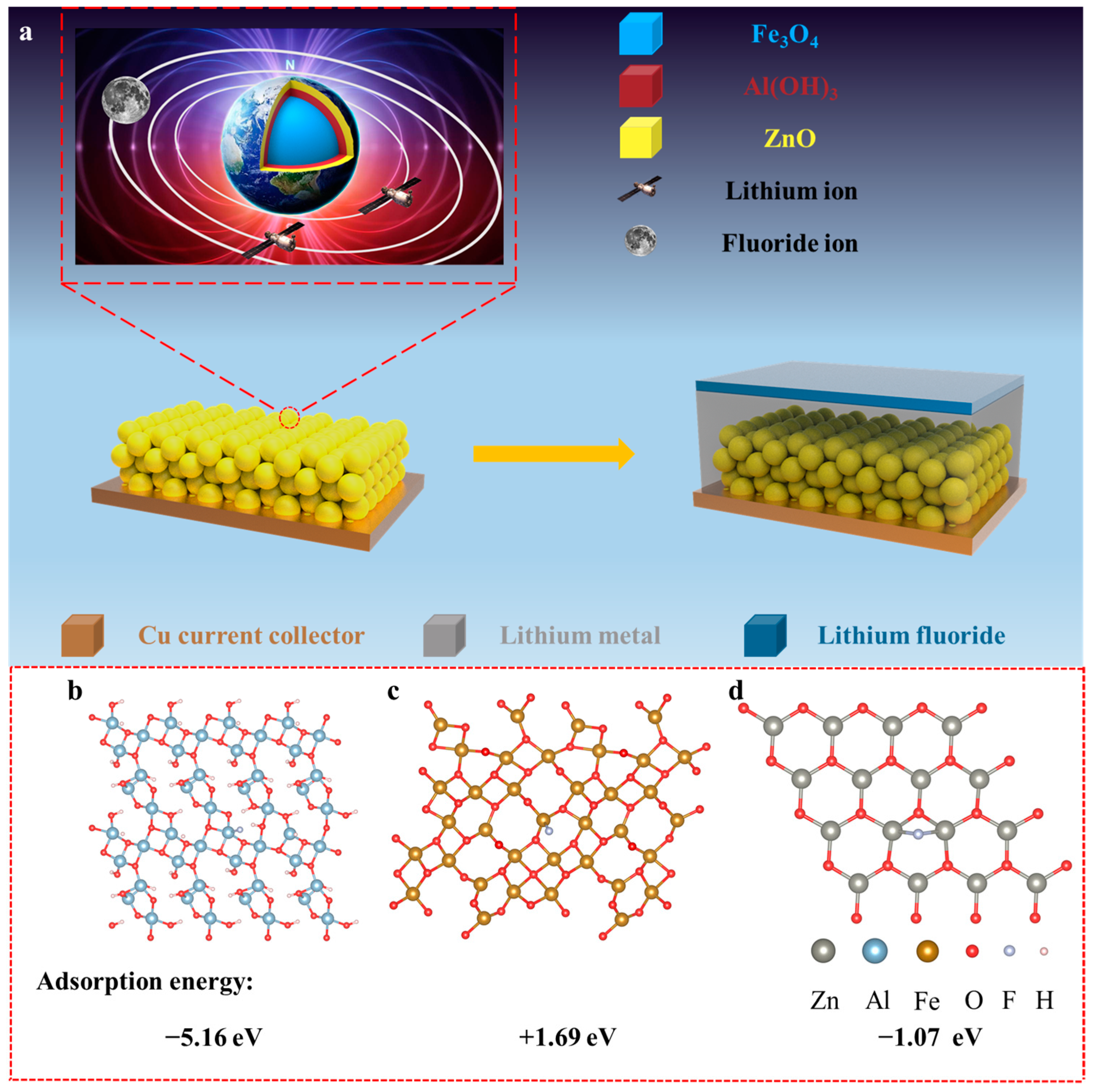
In order to understand the structure and mechanism of the synthesized nanospheres, the nanospheres can be compared to a miniature Earth (Figure 1a). Fe3O4@Al(OH)3@ZnO nanospheres have a structure similar to the Earth’s crust. The adsorption of F− (moon) by Al(OH)3 makes a high concentration of F− close to the nanosphere and ZnO improves the regular nucleation site. Lithium metal can be deposited uniformly, and LiF-rich SEI can be formed by laying nanospheres on copper foil. First of all, in order to prove the adsorption effect of Al(OH)3 on F−, the first principle calculation of DFT was carried out to verify the force between Al(OH)3 and F− from the atomic point of view. The calculation results are shown in Figure 1b–d and Figure S1 (supplementary Materials), Figure 1b and Figure S1a are the top view and side view of F− adsorption by Al(OH)3. It can be seen that the Al atom and F atom are bonded, which means that the Al atom and F atom have an adsorption effect and the F atom and H atom also have the tendency to attract each other, so Al(OH)3 has a strong adsorption effect on F− theoretically. The adsorption energy is calculated to be −5.16 eV. Figure 1c and Figure S1b are the top view and side view of the adsorption of F− by Fe3O4. It can be seen that the crystal structure of Fe3O4 has been greatly changed by the introduction of F−. This is mainly because the O and F− positions repel each other. This means that Fe3O4 theoretically repels F− and the calculated adsorption energy is +1.69 eV, but since Fe3O4 is located in the inner layer of the nanosphere, it does not repel F− macroscopically. In the top view and side view of ZnO adsorbing F− (Figure 1d and Figure S1c), it can be seen that F atoms bond with two Zn atoms, but the repulsion between F atoms and O atoms is also great, resulting in the O atoms leaving the plane position. It is calculated that the adsorption energy of ZnO for F− is −1.07 eV, which indicates that the adsorption energy of ZnO for F− is very low. On the contrary, Al and H atoms in Al(OH)3 adsorb F atoms, and the crystal position of the O atom is far away from the adsorption site of the F atom. As a result, Al(OH)3 has a strong adsorption ability to F−, which can adsorb F− in the electrolyte and form a local electrolyte with high F− concentration on the surface of the nanosphere.
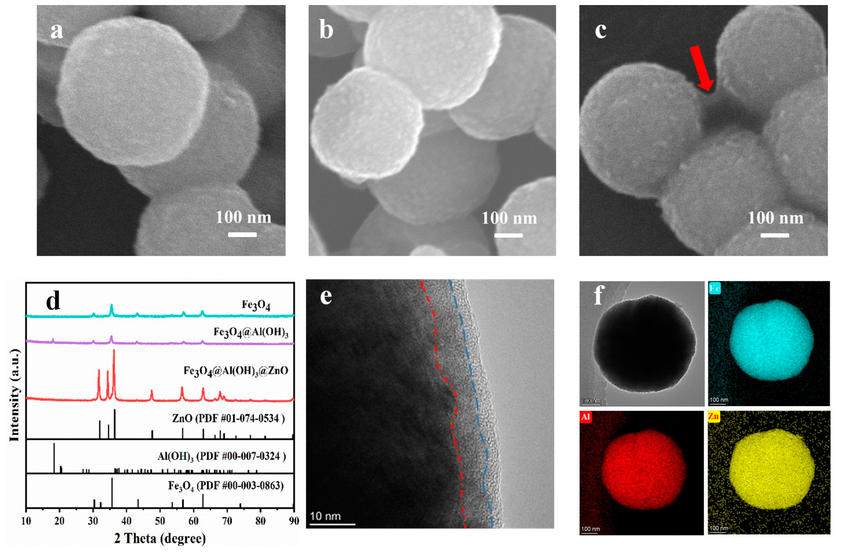
As shown in Figure 2a–c, SEM characterization was conducted on the morphologies of Fe3O4 nanospheres, Fe3O4@Al(OH)3 nanospheres and FAZ nanospheres. The Fe3O4 nanospheres synthesized by hydrothermal method possess the uniform size of about 500 nm. The uniform size nanospheres can distribute uniformly on the copper foil and provide regular distribution of magnetic field, which is more conducive to the homogenization of lithium ions. Then, a trace amount of Al(OH)3 is loaded on the uniform Fe3O4 nanospheres. As shown in Figure 2b, a coating with obvious nanoparticles sensitivity appear on the surface of the originally smooth Fe3O4 nanospheres. There have been many reports that Al3+ has a strong adsorption effect on F−. The Al(OH)3 layer is designed to adsorb more F− on the surface of the nanosphere in the electrolyte, and form a dense LiF layer with the nanosphere as the carrier. Finally, a ZnO layer is loaded on the Fe3O4@Al(OH)3 nanosphere. As can be seen from Figure 2c, a thin film (red arrow) is covered on the nanosphere surface. ZnO is a kind of lithiophilic material, which can form LiZn alloy with lithium metal, and lithium ions tend to nucleate on the surface of ZnO. At the same time, XRD characterizations were conducted on the three kinds of prepared nanospheres (Figure 2d). It can be seen that the XRD patterns obtained are basically consistent with the PDF cards, and the peaks are sharp without stray peaks, which proves that the prepared materials have good crystallinity. In order to more directly observe the layered coating structure of FAZ nanosphere, TEM characterization was also conducted on the nanosphere(Figure 2e). It can be seen that there are very obvious three-layer stratification at the edge of the nanospheres, corresponding to the interface of Fe3O4 and Al(OH)3, the interface of Al(OH)3 and the edge of ZnO, respectively. Fe3O4, Al(OH)3 and ZnO materials form the layered coating structure, which is in perfect agreement with the designed structure. Figure 2f shows the elemental analysis under projection. It can be seen that Fe, Al and Zn elements are evenly distributed on the surface of the nanosphere, which proves the integrity of the layered cladding structure without any broken or missing cladding layer. In summary, the Fe3O4, Al(OH)3 and ZnO multilayer nanospheres are successfully obtained.
2.2. SEM Images of the Nanospheres or Lithium Deposition
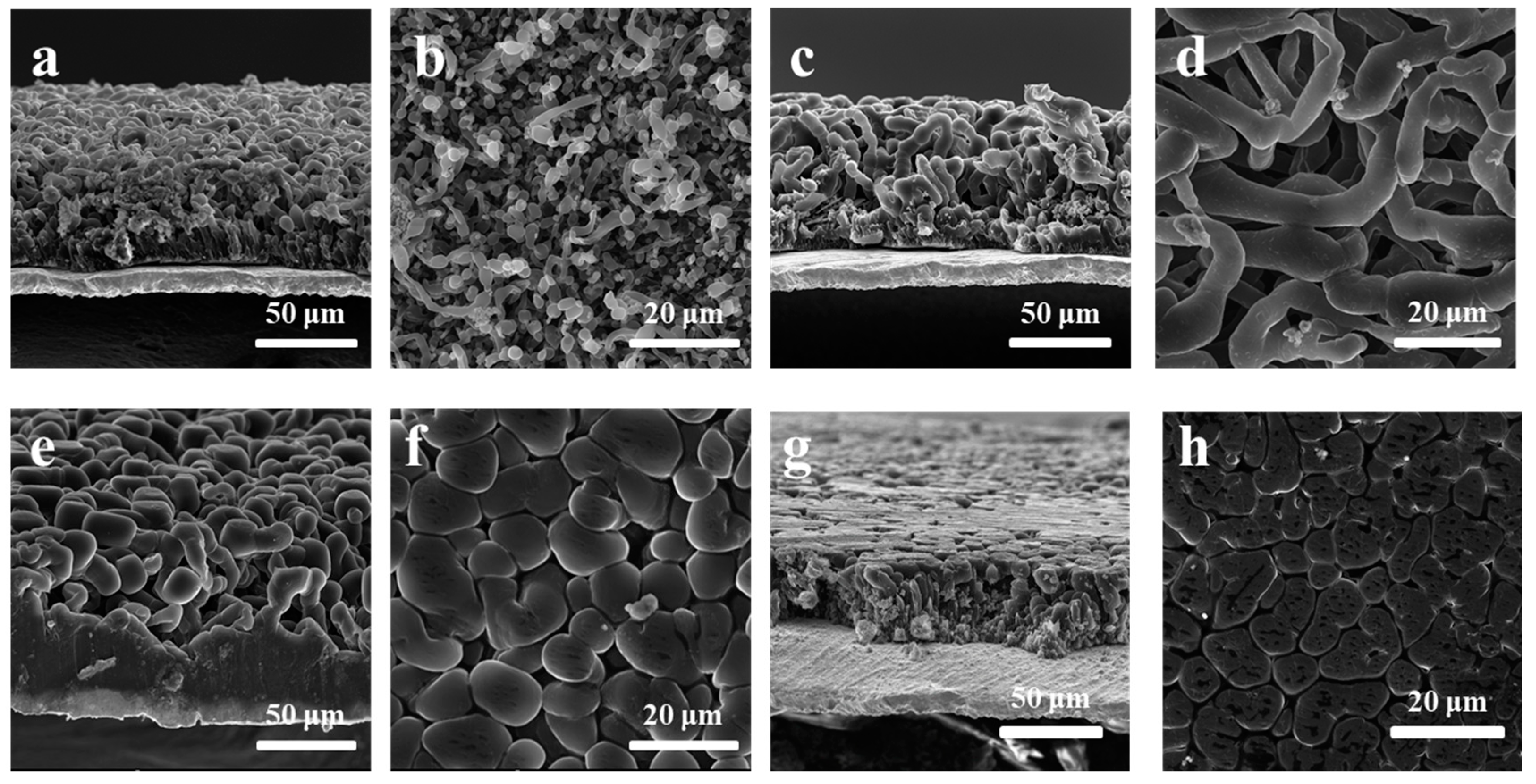
Because the FAZ nanospheres have poor electronic conductivity, it is difficult to directly use them as anode materials. The nanospheres are uniformly loaded on copper foil, where lithium ions will accumulate due to electrical attraction, and the nanospheres loaded on copper foil can be used as a framework for lithium deposition. The ZnO on the outer surface is highly lithium friendly. Lithium can be deposited at the junction of copper foil and ZnO and deposited from the bottom up. Therefore, in the first step of lithium metal deposition, the nanospheres, as the framework to guide lithium deposition, need to load with uniform distribution on the surface of the copper foil. If the distribution is not uniform, the phenomenon of local high current will appear and lithium ions will be preferentially deposited in the position with high current density, which will result in dendrite growth of lithium metal. However, because the nanospheres agglomerate easily in the solution, it is difficult to uniformly deposit on the copper foil. However, with the introduction of Fe3O4 material, it is easy to carry out uniform loading on the copper foil surface under a magnetic field. Figure 3 and Figure S2 shows the SEM images of loading or lithium deposition with different nanosphere structures, which can more directly observe the importance of different material components in lithium metal dense deposition. In order to verify the function of Fe3O4, SiO2@Al(OH)3@ZnO (SAZ) nanospheres of the same scale were specially prepared as a control group for loading on copper foil. The results are shown in Figure S2a. Due to the agglomeration of nanospheres in solution, agglomeration would also occur when the nanospheres were loaded on the surface of the copper foil. However, lithium metal deposition on this surface will lead to serious lithium dendrite growth. Figure S2b shows the SEM cross-section of lithium deposition when SAZ nanospheres are loaded on the copper foil. Above the copper foil, SAZ nanospheres can be seen and residual SEI structures and lithium dendrites are scattered haphazardly. Without the Fe3O4 nanospheres and magnetic field, the nanospheres cannot be uniformly loaded on the copper foil, resulting in the robust growth of lithium dendrites and unlimited generation of SEI, which has a great impact on the performance of lithium metal batteries. When FAZ nanospheres are loaded on the surface of copper foil, parallel magnetic fields are used to carry out magnetic adsorption on the nanospheres. In the process of solvent evaporation, the nanospheres will inhibit the agglomeration and complete planarization under the magnetic drive, as shown in Figure S2c. FAZ nanolayers with a thickness of 3.65 μm are stacked on the copper foil under parallel magnetic fields. After the deposition of lithium metal (Figure S2d), there is no irregular distribution of nanospheres and the growth of lithium dendrites, but the growth of dense and flat lithium metal. Moreover, it is worth noting that at the bottom of the dense lithium metal, there is a 3.63 μm thick layer of FAZ@Li. The thickness here is consistent with the thickness of the loaded FAZ nanospheres, which proves that this nanosphere layer can indeed serve as a framework for lithium metal deposition and guide the dense deposition of lithium metal. In order to verify the influence of various material structures of nanospheres on lithium metal deposition, SAZ, Fe3O4@SiO2@ZnO (FSZ) and Fe3O4@Al(OH)3@SiO2 (FAS) nanospheres were deposited on copper foil respectively, and then lithium metal was deposited on copper foil with the same current density and deposition time. After washing with DOL (1, 3-dioxolane), SEM was used to observe the deposition of lithium metal on the upper surface and section of copper foil, as shown in Figure 3a–h. Firstly, SEM was used to characterize the morphology of SAZ nanospheres after lithium deposition (Figure 3a,b). It can be seen that the lithium metal is basically composed of lithium dendrites, and the growth of lithium dendrites may cause serious security risks. The loose distribution of lithium dendrites and scattered nanospheres can be seen. Loose lithium metal reaction leads to a larger specific surface area, which makes the originally complex interfacial reaction increase exponentially, resulting in the unrestricted growth of SEI and consumption of lithium resources. The Fe3O4 facilitates the uniform, orderly and compact packing of nanospheres on the copper foil, and the magnetic field effect generated by it can also homogenize the movement of lithium ions, reduce the concentration gradient of lithium ions during diffusion, and inhibit the generation of lithium dendrites. In the absence of Fe3O4, the copper foil and nanospheres do not form a dense combination at first, nor can they regulate the movement of lithium ions, which will result in the unlimited growth of lithium dendrites and SEI, resulting in serious security risks. Figure 3c shows the cross section of FAS nanospheres deposited on the copper foil surface and deposited lithium metal. It can be seen that a large number of lithium dendrites still exist on the cross section. However, the thickness of the lithium dendrites (Figure 3d) is obviously coarser than that in Figure 3b. This is because when the nanospheres are densely loaded on the copper foil, a small amount of loaded Al(OH)3 has a strong adsorption effect on F− in the electrolyte. When lithium metal is in contact with the electrolyte, it is in the electrolyte environment with high-fluoride ion concentration. The growth of the lithium metal is accompanied by the production of a large amount of LiF, which inhibits the longitudinal growth of lithium dendrites and promotes the transverse expansion of the lithium metal. However, due to the absence of ZnO, lithium ions tend to nucleate on conductive copper foil, and the growth of the lithium metal on the copper foil has great randomness. The growth of the lithium metal depends largely on the current density of the collector surface, so the growth of lithium dendrites cannot be avoided even under the action of the magnetic field and high concentration of F−. When FSZ nanospheres were used to stack densely on the copper foil and deposit lithium metal, it was found that the growth of lithium dendrites was significantly inhibited from cross section observation (Figure 3e). When observed from above, lithium metal grows upward in a columnar form, but the accumulation of lithium metal is not dense. This indicates that when FSZ nanospheres are spread on the surface of copper foil, lithium ions tend to nucleate at the intersection point between the surface of copper foil and ZnO nanospheres, and then grow upward along the nanospheres. Moreover, due to the regular and dense accumulation of nanospheres, regular and dense active lithium deposition sites are also formed on the copper foil surface, which can effectively reduce the local current density on the surface of the collector body during the deposition of lithium, so that the lithium metal can grow evenly. However, without the adsorption of F− by Al(OH)3, there is no high concentration of F− to produce a large amount of LiF to inhibit the dendrite growth of lithium during the deposition of the lithium metal. When the deposition height of lithium metal is higher than that of the deposited nanospheres, the effect of ZnO nanospheres on the growth of the upper lithium metal is weak. In the following growth of the lithium metal, dendrite growth will inevitably occur, resulting in the thick but loose lithium metal deposition in Figure 3f. When FAZ nanospheres were used to accumulate in a compact way on the surface of copper foil, lithium ions would preferentially nucleate and grow at the junction of copper foil and ZnO, and the nanospheres were used as frameworks for upward compact growth. Al(OH)3 will adsorb F−, forming an electrolyte with local high-fluoride concentration on the surface of copper foil and a SEI layer with LiF as the main component during the growth of the lithium metal. High mechanical strength LiF will inhibit the dendrization of lithium metal, and the density of the lithium metal deposition can also be achieved in the upper part of the accumulation layer of nanospheres. Figure 3g shows the cross section of lithium deposited on the copper foil by FAZ nanospheres. It can be seen that lithium is deposited in a very dense manner. Figure 3h shows that the surface of the lithium is flat and there are almost no pores. This indicates that copper foil modified with FAZ nanospheres can effectively inhibit the growth of lithium dendrites and complete the densification and accumulation of lithium metals.
2.3. In Situ XPS Etching Performance
In order to verify the influence of Al(OH)3 on lithium metal deposition, the SEI layer generated during lithium metal deposition must be characterized. First of all, in situ XPS etchings of the SEI layer derived from the copper foil were performed to understand the growth of the SEI layer generated by lithium metal deposition without any protection. Elements C, F, N and O were tested when the etching time was 0 s, 50 s, 100 s, 150 s and 200 s, and the results were shown in Figure S3 (blank copper foil). In the element C, the main form of element C on the surface of the SEI is organic lithium salt, which has been reported in many papers. The mechanical strength of the organic SEI layer is too low to inhibit the lithium dendrite. When the dendrite breaks through the organic SEI, the lithium metal re-contacts with the electrolyte to form a new SEI layer, and the final result is the unlimited dendrite and loss of lithium metal. With the increase in etching time, the content of each component of the element decreases gradually, which indicates that the organic SEI decreases. In the XPS etching of F, it can be seen that the main form of F on the surface of the SEI layer is -CF3, while the content of LiF is less. As the etching time increases, the component of LiF gradually increases. In the XPS etching of N elements, the surface of the SEI layer contains a large amount of Li3N and a small amount of LiNO3 and LiNO2, and their contents also decrease with the increase in etching time. In the XPS etching O element, the content of O-C=O bond is very high, which indicates that the surface of the SEI layer contains a large number of organic layers, and the Li2O peak gradually appears with the increase in etching time. Combined with the above XPS etching analysis, it can be analyzed that the structure of the SEI layer is a double-layer mosaic structure, the upper part is divided into organic layer with low mechanical strength, and the lower part is divided into inorganic layer with strong mechanical strength [12,13,14,15]. The boundary between the organic layer and inorganic layer is not obvious, and organic salt is embedded in it [19]. The SEI layer of this structure is easy to damage in the volume expansion caused by the growth of lithium metal, which causes serious consequences.
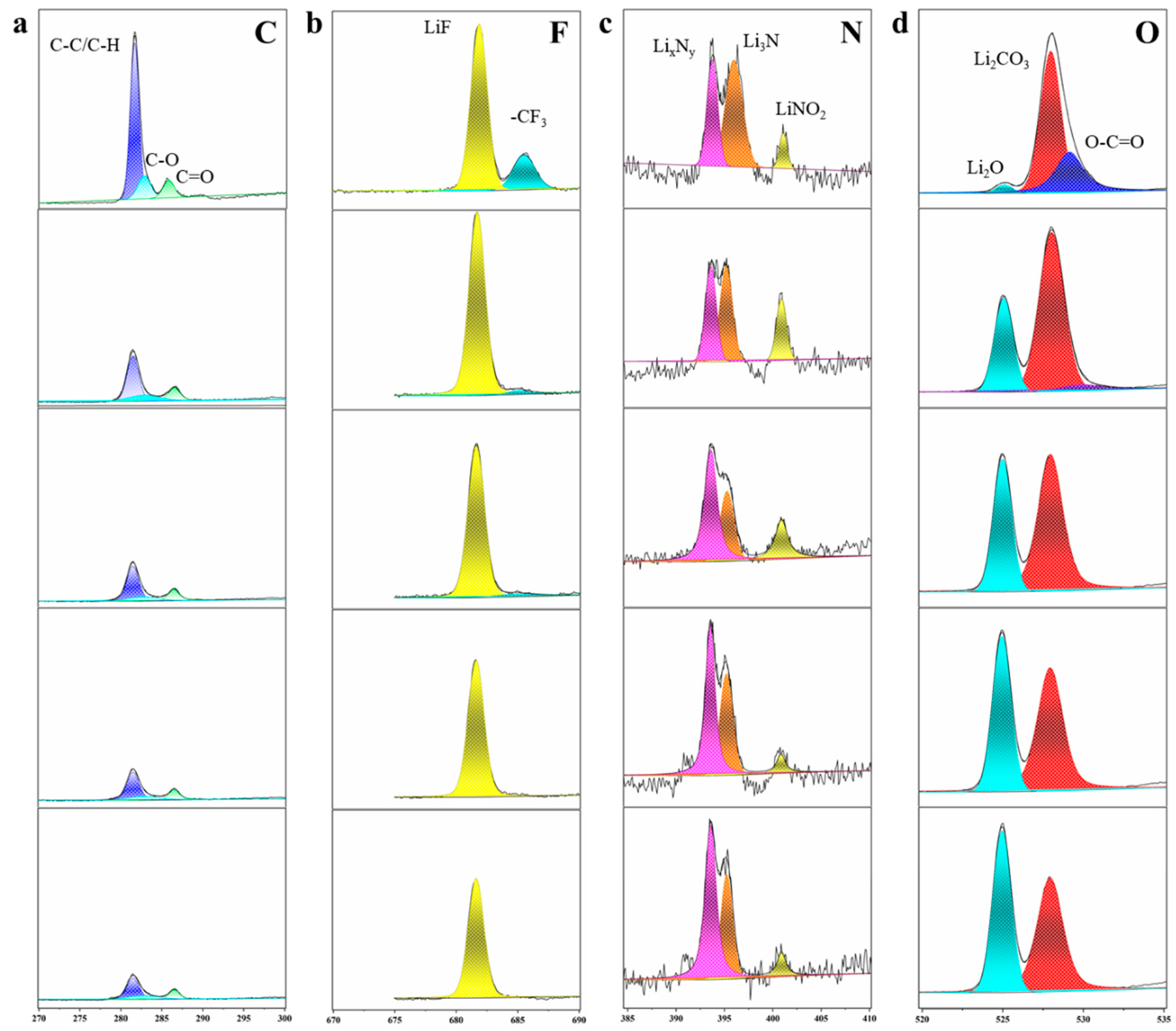
After the copper foil was modified with FAZ nanospheres, the results obtained by in situ XPS etching were quite different (Figure 4). In the XPS etching map of the C element, the C element on the surface of the SEI mainly exists as C-C/C-H bonds, and the organic salt peaks are almost invisible, indicating that the upper part of the SEI layer is no longer organic. The F etching results show that the F on the surface of the SEI layer mainly exists in the form of LiF, and with the increase in the etching time, the peak height attenuation degree is small, which means that the content of LiF always exists to a high degree in the deeper SEI layer. In the XPS etching N elements, the N elements can be divided into LixNy, Li3N and LiNO2. In the XPS etching O element, it can be seen that the O on the surface of the SEI layer is mainly composed of Li2CO3, and small amounts of Li2O and organic lithium salt also exist on the surface of the SEI layer. With the increase in etching time, the peak of the organic layer disappears, while the peak of Li2O increases. This is because the deeper the etching depth is, the closer it is to the lithium nucleation site of ZnO on the surface of the nanosphere, and the ZnO reacts with lithium to form Li2O, so the Li2O peak will increase. Furthermore, the loose ZnO coating can allow the electrolyte to penetrate into the interior of the nanosphere, make the Al(OH)3 in the inner layer contact with the electrolyte and the Al(OH)3 absorb the F− in the electrolyte. At the same time, in order to explore the content changes of each component in the SEI layer under different etching times, the element content of the SEI layer was detected and the results are shown in Figure S4. Figure S4a shows the XPS content analysis of the SEI layer obtained on the blank copper foil. It can be seen that the content of N element is low in the whole etching process, while the content of F element remains stable at about 20% during the etching process, which means that LiF also exists inlaid in the SEI layer. The content of C reaches 45.2% on the surface and decreases gradually with the increase in the etching depth. On the contrary, the content of O increases gradually due to the reduction in the C element. The characterization results of XPS content in the SEI layer generated by FAZ nanospheres are shown in Figure S4b. The content of nitrogen has always been low, but the content of F has reached 43.5% on the surface. This indicates that LiF has occupied the main component on the surface of the SEI layer, and the content of F also increases with the increase in the etching depth, which indicates that the content of LiF is always very high in the whole SEI layer. However, in the component content of the C element and O element, the content of the C element is always low, which means that the content of organic SEI layer is the same. The content of the O element is also low, which is mainly due to the high content and activity of F− in the electrolyte. In the process of lithium metal contact with the electrolyte, the LiF interface layer with stable chemical properties and mechanical strength will be preferentially formed. In summary, the introduction of Al(OH)3 can adsorb F− in the electrolyte and form a local electrolyte with a high concentration of F− around the lithium ions during lithium nucleation, resulting in the formation of a lithium metal surface rich in the LiF SEI layer, which can not only effectively inhibit the growth of lithium dendrites, but also limit the fracture and regeneration of the SEI layer. It has a strong effect on the performance improvement of the lithium metal battery. Figure S5 shows the TEM image of FAZ nanospheres after lithium metal deposition. In the elemental analysis, the F element is evenly distributed on the nanospheres, which indicates that LiF is evenly loaded on the nanospheres. This also confirms the adsorption of F− by Al(OH)3.
2.4. Electrochemical Performances of Various Nanospheres
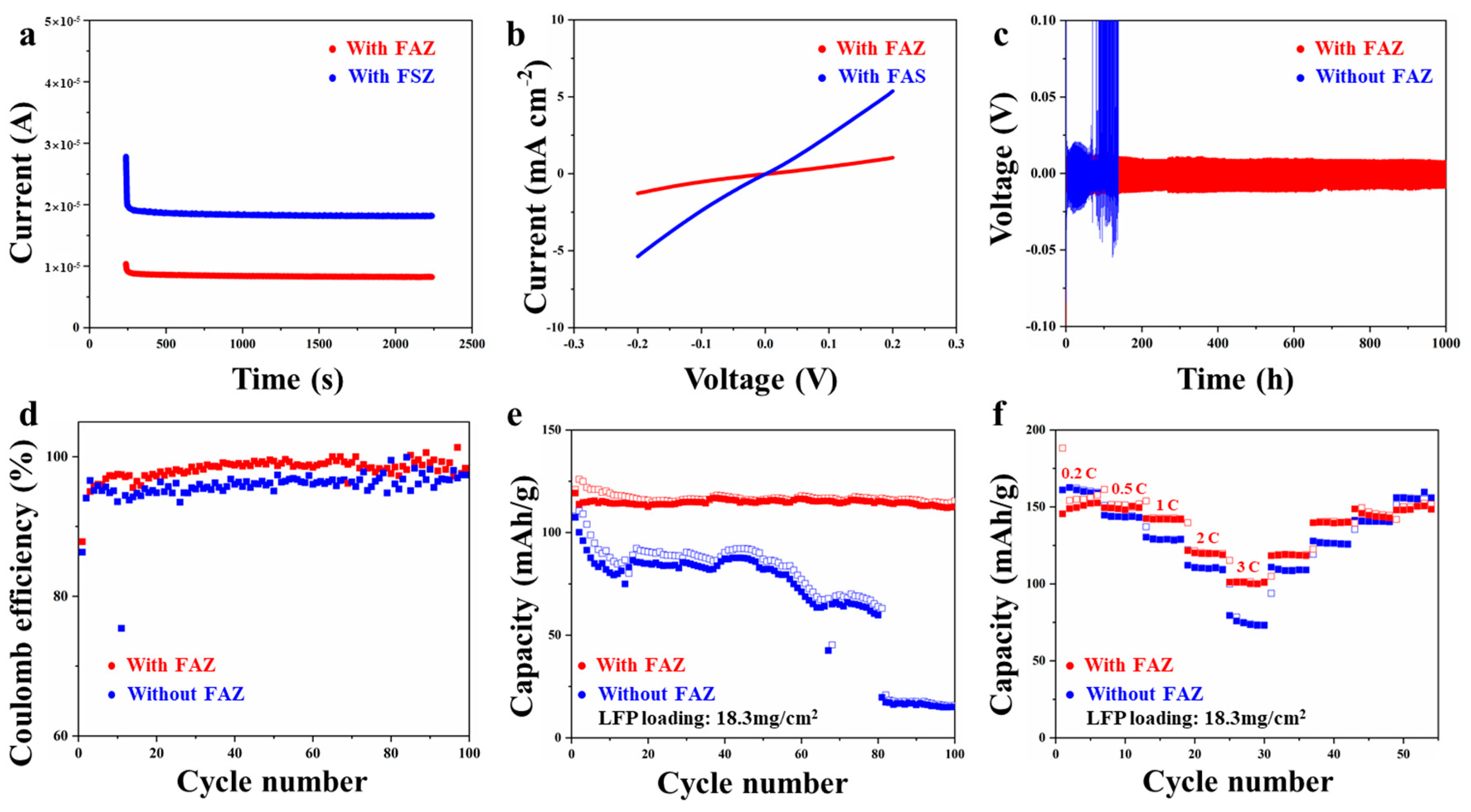
In order to verify the influence of various components of FAZ nanospheres on the electrochemical performance of batteries, various electrochemical performances on different kinds of nanospheres were carried out. Firstly, in order to verify the adsorption effect of F− after the introduction of Al(OH)3, the transference number of lithium ions in the battery was tested. When F− are adsorbed by Al(OH)3, the transference number of negative ions will be blocked, and the total transference number of ions depends on the sum of the transference numbers of positive and negative ions. When the migration of F− is blocked, the transference number of lithium ions will increase. The degree of lithium ion migration represents the capacity of lithium ion migration. After the battery has been standing for a period of time, the measured current was divided by the initial current. The results show that the lithium ion transference number of the batteries assembled by FAZ is 0.81 (Figure 5a). It is much higher than the ion transference number 0.65 of the battery assembled by FSZ, which confirms the adsorption effect of Al(OH)3 on F−. When the transference number of lithium ions is increased, the diffusion gradient concentration of lithium ions will be reduced and the generation of lithium dendrites will be inhibited. In order to verify that the introduction of ZnO can provide lithium ion nucleation sites uniformly and effectively, the exchange current densities of the batteries were tested. When FAZ nanospheres were used to modify copper foil, the dense and regularly distributed ZnO nanospheres would form regular lithium ion nucleation sites on the copper foil. The uniform nucleation of lithium metal can effectively reduce the exchange current density, avoid the occurrence of a local high current and inhibit the generation of lithium dendrites. The test results are shown in Figure 5b. By calculating the Tafel slopes (Figure S6), the exchange current density of the battery assembled by FAZ nanospheres is 0.52 mA/cm2, much lower than the 1.13 mA/cm2 of the battery modified with FAS nanospheres, which indicates that the addition of ZnO nanospheres can effectively reduce the exchange current density and inhibit the formation of lithium dendrites. We considered the electrochemical performance of batteries assembled using FAZ nanospheres and batteries assembled using blank copper foil. Firstly, the cycle performances of Li||Li symmetric batteries were tested (Figure 5c). It can be seen that under the condition of modified copper foil, the Li||Li symmetric battery can cycle stably for more than 1000 h under the condition of 1 mA/cm2−1 mAh/cm2. However, the battery assembled by the unmodified copper foil displayed serious polarization at about 140 h. Then the Coulombic efficiencies of Li||Cu batteries were tested (Figure 5d). It can be seen that the Coulombic efficiency of the battery assembled with modified copper foil is more stable, while the Coulombic efficiency of the battery assembled with unmodified copper foil shows a sharp decline around the 70th cycle. The calculated Coulombic efficiency of the FAZ battery is 98.6%, while the Coulombic efficiency of the unmodified battery is 96.4%, which indicates that the introduction of FAZ significantly improves the Coulombic efficiency of the battery and maintains the battery cycle stability. In order to verify that the modified copper foil can also show good electrochemical performance in lithium metal batteries, lithium metal batteries were assembled with a LiFePO4 cathode with a high loading of 18.3 mg/cm2 to test the cycle performance and rate performance. Figure 5e shows the cycle performance of the LFP||Li metal battery at 1 C. It can be seen that the capacity of the lithium metal battery assembled by the modified copper foil remains stable with a capacity retention rate of 87% after 100 cycles, while the battery capacity of the lithium metal battery without any modification continuously declines under the condition of high loading. When the cycle number reaches about 80 times, the capacity of the battery suffers a collapse. This may be because under high load condition, the high current density in the battery is more likely to cause the growth of lithium dendrites. Then the rate performance of LFP||Li metal batteries was also tested. When the current density increased from 0.2 C to 0.5 C, the capacity attenuation trend of the two lithium metal batteries was the same. When the current density increased, the redox activity inside the battery could not match the electron transfer speed, so the reaction would be incomplete. When the capacity drops sharply, it indicates that the electrochemical kinetic speed inside the battery is damaged under high current density, which may be caused by the growth of lithium dendrites. As shown in the Figure 5f, when the current density increased to 1 C, 2 C and 3 C, the capacity of the battery assembled with the unmodified copper foil showed a decline (34% decrease for 3 C), while the capacity of the battery assembled with the copper foil modified with FAZ nanospheres did not decrease significantly (17% decrease for 3 C). This indicates that the introduction of nanospheres could homogenize the exchange current density and prevent the generation of local high currents from damaging the electrochemical dynamics of the battery.
3. Conclusions
In conclusion, we designed a multilayer and multifunctional FAZ nanosphere structure for lithium metal anode modification. Nanospheres spread on the surface of the current collector can homogenize the deposition of lithium ions and absorb F− in the electrolyte to create a local electrolyte with high F− concentration. This forms LiF with high ion conductivity on the surface of lithium metal. Even under the high load of 18.3 mg/cm2 LFP, 87% capacity is maintained after 100 cycles. This structure is expected to offer a new idea for the development of a new kind of low-fluoride lithium metal battery.
Supplementary Materials
The following supporting information can be downloaded at: https://www.mdpi.com/article/10.3390/batteries9030149/s1, Reference [43] is cited in the Supplementary Materials. Figure S1: Adsorption model of (a) Al(OH)3 and F−, (b) Fe3O4 and F−, (c) ZnO and F− at top view. Figure S2: (a) SAZ nanospheres deposited in copper foil. (b) Lithium deposition on SAZ nanospheres. (c) FAZ nanospheres deposited in copper foil. (d) Lithium deposition on FAZ nanospheres. Figure S3: In situ XPS etching tests for C, F, N and O elements at 0, 50, 100, 150 and 200 s on lithium metal deposited on blank copper foil. Figure S4: In situ XPS etching tests for C, F, N and O elements at 0, 50, 100, 150 and 200 s. The histogram of the element ratio for N, F, C and O elements at 0, 50, 100, 150 and 200 s on (a) blank copper foil, and (b) FAZ nanospheres. Figure S5: The TEM and element mapping images of FAZ nanospheres after lithium deposition. Figure S6: Tafel plots obtained from cyclic voltammetry test in Li||Li battery.
Author Contributions
Y.L. and M.X. contributed equally to this work. Y.Z. and X.X.: Writing—Reviewing and Editing, Supervision. Y.L. and M.X.: Writing original draft preparation. C.S. and L.C.: Formal analysis. W.Y.: Visualization. T.Z. and H.M.: Resources. All authors have read and agreed to the published version of the manuscript.
Funding
This work was supported by the Hainan Provincial Joint Project of Sanya Yazhou Bay Science and Technology City (520LH056), Sanya Science and Education Innovation Park of Wuhan University of Technology (2022KF0010).
Data Availability Statement
The data that support the findings of this study are available from the corresponding author upon reasonable request.
Conflicts of Interest
The authors declare no conflict of interest.
References
- Lin, D.; Liu, Y.; Cui, Y. Reviving the lithium metal anode for high-energy batteries. Nat. Nanotechnol. 2017, 12, 194–206. [Google Scholar] [CrossRef] [PubMed]
- Ding, J.-F.; Xu, R.; Yan, C.; Li, B.-Q.; Yuan, H.; Huang, J.-Q. A review on the failure and regulation of solid electrolyte interphase in lithium batteries. J. Energy Chem. 2021, 59, 306–319. [Google Scholar] [CrossRef]
- Shen, X.; Zhang, X.-Q.; Ding, F.; Huang, J.-Q.; Xu, R.; Chen, X.; Yan, C.; Su, F.-Y.; Chen, C.-M.; Liu, X.; et al. Advanced Electrode Materials in Lithium Batteries: Retrospect and Prospect. Energy Mater. Adv. 2021, 15, 1205324. [Google Scholar] [CrossRef]
- Jiang, F.; Yang, S.; Liu, H.; Cheng, X.; Liu, L.; Xiang, R.; Zhang, Q.; Kaskel, S.; Huang, J. Mechanism understanding for stripping electrochemistry of Li metal anode. Susmat 2021, 1, 506–536. [Google Scholar] [CrossRef]
- Xu, W.; Wang, J.; Ding, F.; Chen, X.; Nasybulin, E.; Zhang, Y.; Zhang, J.-G. Lithium metal anodes for rechargeable batteries. Energy Environ. Sci. 2014, 7, 513–537. [Google Scholar] [CrossRef]
- Louli, A.J.; Eldesoky, A.; Weber, R.; Genovese, M.; Coon, M.; Degooyer, J.; Deng, Z.; White, R.T.; Lee, J.; Rodgers, T.; et al. Diagnosing and correcting anode-free cell failure via electrolyte and morphological analysis. Nat. Energy 2020, 5, 693–702. [Google Scholar] [CrossRef]
- Chen, H.; Yang, Y.; Boyle, D.T.; Jeong, Y.K.; Xu, R.; de Vasconcelos, L.S.; Huang, Z.; Wang, H.; Wang, H.; Huang, W.; et al. Free-standing ultrathin lithium metal–graphene oxide host foils with controllable thickness for lithium batteries. Nat. Energy 2021, 6, 790–798. [Google Scholar] [CrossRef]
- Huang, W.; Yu, Y.; Hou, Z.; Liang, Z.; Zheng, Y.; Quan, Z.; Lu, Y.-C. Dendrite-Free lithium electrode enabled by graphene aerogels with gradient porosity. Energy Storage Mater. 2020, 33, 329–335. [Google Scholar] [CrossRef]
- Weber, R.; Genovese, M.; Louli, A.J.; Hames, S.; Martin, C.; Hill, I.G.; Dahn, J.R. Long cycle life and dendrite-free lithium morphology in anode-free lithium pouch cells enabled by a dual-salt liquid electrolyte. Nat. Energy 2019, 4, 683–689. [Google Scholar] [CrossRef]
- Li, Z.; He, Q.; Xu, X.; Zhao, Y.; Liu, X.; Zhou, C.; Ai, D.; Xia, L.; Mai, L. A 3D Nitrogen-Doped Graphene/TiN Nanowires Composite as a Strong Polysulfide Anchor for Lithium-Sulfur Batteries with Enhanced Rate Performance and High Areal Capacity. Adv. Mater. 2018, 30, e1804089. [Google Scholar] [CrossRef]
- Nanda, S.; Gupta, A.; Manthiram, A. Anode-Free Full Cells: A Pathway to High-Energy Density Lithium-Metal Batteries. Adv. Energy Mater. 2021, 11, 2000804. [Google Scholar] [CrossRef]
- Wang, Z.; Chen, T.; Liu, Y.; Xing, J.; Zhou, A.; Li, J.; Zou, W.; Zhou, F. LiF headspace affixed metallic Li composite enables Li accommodation on the anode surface with excellent electrochemical performance. Chem. Eng. J. 2022, 430, 132970. [Google Scholar] [CrossRef]
- Kim, H.; Kim, Y.S.; Yoo, J. An in situ formed LiF protective layer on a Li metal anode with solvent-less cross-linking. Sustain. Energy Fuels 2020, 4, 3282–3287. [Google Scholar] [CrossRef]
- Lang, J.; Long, Y.; Qu, J.; Luo, X.; Wei, H.; Huang, K.; Zhang, H.; Qi, L.; Zhang, Q.; Li, Z.; et al. One-pot solution coating of high quality LiF layer to stabilize Li metal anode. Energy Storage Mater. 2019, 16, 85–90. [Google Scholar] [CrossRef]
- Liu, S.; Ma, Y.; Wang, J.; Zuo, P.; Du, C.; Yin, G.; Gao, Y. Regulating Li deposition by constructing homogeneous LiF protective layer for high-performance Li metal anode. Chem. Eng. J. 2022, 427, 131625. [Google Scholar] [CrossRef]
- Wang, L.; Fu, S.; Zhao, T.; Qian, J.; Chen, N.; Li, L.; Wu, F.; Chen, R. In situ formation of a LiF and Li–Al alloy anode protected layer on a Li metal anode with enhanced cycle life. J. Mater. Chem. A 2020, 8, 1247–1253. [Google Scholar] [CrossRef]
- Jiang, J.; Ou, Y.; Lu, S.; Shen, C.; Li, B.; Liu, X.; Jiang, Y.; Zhao, B.; Zhang, J. In-situ construction of Li-Mg/LiF conductive layer to achieve an intimate lithium-garnet interface for all-solid-state Li metal battery. Energy Storage Mater. 2022, 50, 810–818. [Google Scholar] [CrossRef]
- Jiang, P.; Cao, J.; Wei, B.; Qian, G.; Wang, S.; Shi, Y.; Du, G.; Lu, X.; Ouyang, C.; Cao, F.; et al. LiF involved interphase layer enabling thousand cycles of LAGP-based solid-state Li metal batteries with 80% capacity retention. Energy Storage Mater. 2022, 48, 145–154. [Google Scholar] [CrossRef]
- Yuan, Y.; Wu, F.; Bai, Y.; Li, Y.; Chen, G.; Wang, Z.; Wu, C. Regulating Li deposition by constructing LiF-rich host for dendrite-free lithium metal anode. Energy Storage Mater. 2019, 16, 411–418. [Google Scholar] [CrossRef]
- Yu, Y.; Huang, G.; Wang, J.; Li, K.; Ma, J.; Zhang, X. In Situ Designing a Gradient Li+ Capture and Quasi-Spontaneous Diffusion Anode Protection Layer toward Long-Life Li−O2 Batteries. Adv. Mater. 2020, 32, 2004157. [Google Scholar] [CrossRef]
- Peng, Z.; Zhao, N.; Zhang, Z.; Wan, H.; Lin, H.; Liu, M.; Shen, C.; He, H.; Guo, X.; Zhang, J.-G.; et al. Stabilizing Li/electrolyte interface with a transplantable protective layer based on nanoscale LiF domains. Nano Energy 2017, 39, 662–672. [Google Scholar] [CrossRef]
- Zhang, X.-Q.; Chen, X.; Xu, R.; Cheng, X.-B.; Peng, H.-J.; Zhang, R.; Huang, J.-Q.; Zhang, Q. Columnar Lithium Metal Anodes. Angew. Chem. Int. Ed. 2017, 56, 14207–14211. [Google Scholar] [CrossRef] [PubMed]
- Shadike, Z.; Lee, H.; Borodin, O.; Cao, X.; Fan, X.; Wang, X.; Lin, R.; Bak, S.-M.; Ghose, S.; Xu, K.; et al. Identification of LiH and nanocrystalline LiF in the solid–electrolyte interphase of lithium metal anodes. Nat. Nanotechnol. 2021, 16, 549–554. [Google Scholar] [CrossRef]
- Xu, R.; Han, F.; Ji, X.; Fan, X.; Tu, J.; Wang, C. Interface engineering of sulfide electrolytes for all-solid-state lithium batteries. Nano Energy 2018, 53, 958–966. [Google Scholar] [CrossRef]
- Zhao, Y.; Wei, K.; Wu, H.; Ma, S.; Li, J.; Cui, Y.; Dong, Z.; Cui, Y.; Li, C. LiF Splitting Catalyzed by Dual Metal Nanodomains for an Efficient Fluoride Conversion Cathode. ACS Nano 2019, 13, 2490–2500. [Google Scholar] [CrossRef]
- Huang, Y.; Li, R.; Weng, S.; Zhang, H.; Zhu, C.; Lu, D.; Sun, C.; Huang, X.; Deng, T.; Fan, L.; et al. Eco-friendly electrolytes via a robust bond design for high-energy Li metal batteries. Energy Environ. Sci. 2022, 15, 4349–4361. [Google Scholar] [CrossRef]
- Qi, S.; Wang, H.; He, J.; Liu, J.; Cui, C.; Wu, M.; Li, F.; Feng, Y.; Ma, J. Electrolytes enriched by potassium perfluorinated sulfonates for lithium metal batteries. Sci. Bull. 2021, 66, 685–693. [Google Scholar] [CrossRef]
- Xiao, J.; Zhang, X.; Fan, H.; Zhao, Y.; Su, Y.; Liu, H.; Li, X.; Su, Y.; Yuan, H.; Pan, T.; et al. Stable Solid Electrolyte Interphase In Situ Formed on Magnesium-Metal Anode by using a Perfluorinated Alkoxide-Based All-Magnesium Salt Electrolyte. Adv. Mater. 2022, 34, 2203783. [Google Scholar] [CrossRef]
- Luo, J.; Bi, Y.; Zhang, L.; Zhang, X.; Liu, T.L. A Stable, Non-Corrosive Perfluorinated Pinacolatoborate Mg Electrolyte for Rechargeable Mg Batteries. Angew. Chem. Int. Ed. 2019, 58, 6967–6971. [Google Scholar] [CrossRef]
- Qiu, F.; Ren, S.; Zhang, X.; He, P.; Zhou, H. A high efficiency electrolyte enables robust inorganic–organic solid electrolyte interfaces for fast Li metal anode. Sci. Bull. 2021, 66, 897–903. [Google Scholar] [CrossRef]
- Qiu, F.; Li, X.; Deng, H.; Wang, D.; Mu, X.; He, P.; Zhou, H. A Concentrated Ternary-Salts Electrolyte for High Reversible Li Metal Battery with Slight Excess Li. Adv. Energy Mater. 2019, 9, 1803372. [Google Scholar] [CrossRef]
- Peng, Z.; Cao, X.; Gao, P.; Jia, H.; Ren, X.; Roy, S.; Li, Z.; Zhu, Y.; Xie, W.; Liu, D.; et al. High-Power Lithium Metal Batteries Enabled by High-Concentration Acetonitrile-Based Electrolytes with Vinylene Carbonate Additive. Adv. Funct. Mater. 2020, 30, 2001285. [Google Scholar] [CrossRef]
- Chen, S.; Zheng, J.; Mei, D.; Han, K.S.; Engelhard, M.H.; Zhao, W.; Xu, W.; Liu, J.; Zhang, J. High-Voltage Lithium-Metal Batteries Enabled by Localized High-Concentration Electrolytes. Adv. Mater. 2018, 30, e1706102. [Google Scholar] [CrossRef] [PubMed]
- Lin, Y.; Zhang, X.; Liu, Y.; Wang, Q.; Lin, C.; Chen, S.; Zhang, Y. Ultra-stable Li||LiFePO4 batteries via advanced designing of localized high concentration electrolyte. J. Colloid Interface Sci. 2022, 628, 14–23. [Google Scholar] [CrossRef] [PubMed]
- May, R.; Hestenes, J.C.; Munich, N.A.; Marbella, L.E. Fluorinated ether decomposition in localized high concentration electrolytes. J. Power Sources 2023, 553, 232299. [Google Scholar] [CrossRef]
- Zheng, Y.; Soto, F.A.; Ponce, V.; Seminario, J.M.; Cao, X.; Zhang, J.-G.; Balbuena, P.B. Localized high concentration electrolyte behavior near a lithium–metal anode surface. J. Mater. Chem. A 2019, 7, 25047–25055. [Google Scholar] [CrossRef]
- Chang, C.; Yao, Y.; Li, R.; Cong, Z.; Li, L.; Guo, Z.H.; Hu, W.; Pu, X. Stable lithium metal batteries enabled by localized high-concentration electrolytes with sevoflurane as a diluent. J. Mater. Chem. A 2022, 10, 9001–9009. [Google Scholar] [CrossRef]
- Zhang, G.; Deng, X.; Li, J.; Wang, J.; Shi, G.; Yang, Y.; Chang, J.; Yu, K.; Chi, S.-S.; Wang, H.; et al. A bifunctional fluorinated ether co-solvent for dendrite-free and long-term lithium metal batteries. Nano Energy 2022, 95, 107014. [Google Scholar] [CrossRef]
- Gao, P.; Wu, H.; Zhang, X.; Jia, H.; Kim, J.; Engelhard, M.H.; Niu, C.; Xu, Z.; Zhang, J.; Xu, W. Optimization of Magnesium-Doped Lithium Metal Anode for High Performance Lithium Metal Batteries through Modeling and Experiment. Angew. Chem. Int. Ed. 2021, 60, 16506–16513. [Google Scholar] [CrossRef]
- Beltran, S.P.; Cao, X.; Zhang, J.-G.; El-Khoury, P.Z.; Balbuena, P.B. Influence of diluent concentration in localized high concentration electrolytes: Elucidation of hidden diluent-Li+ interactions and Li+ transport mechanism. J. Mater. Chem. A 2021, 9, 17459–17473. [Google Scholar] [CrossRef]
- Li, Y.; Xiao, M.; Shen, C.; Cui, L.; Yang, W.; Zhang, C.; Chen, X.; Mai, L.; Zhao, Y.; Xu, X. Three-dimensional SEI framework induced by ion regulation in toroidal magnetic field for lithium metal battery. Cell Rep. Phys. Sci. 2022, 3, 101080. [Google Scholar] [CrossRef]
- Xiu-Lan, Y.U.; Wang, Z.C.; Han, Y.X.; Zeng, F.W.; Zhang, Q. Extraction of Rare Earths from Baogang Tailings by Carbochlorination Reaction Taking AlCl3 as Defluorinating Agent; Chinese Rare Earths: Shenyang, China, 2006. [Google Scholar]
- Shao, M.; Ning, F.; Zhao, J.; Wei, M.; Evans, D.G.; Duan, X. Preparation of Fe3O4@SiO2@Layered Double Hydroxide Core–Shell Microspheres for Magnetic Separation of Proteins. J. Am. Chem. Soc. 2012, 134, 1071–1077. [Google Scholar] [CrossRef] [PubMed]
Figure 1.
Mechanism introduction and first principles calculation. (a) Structure and mechanism of FAZ nanospheres. Adsorption model of (b) Al(OH)3 and F−, (c) Fe3O4 and F−, (d) ZnO and F− at top view.
Figure 1.
Mechanism introduction and first principles calculation. (a) Structure and mechanism of FAZ nanospheres. Adsorption model of (b) Al(OH)3 and F−, (c) Fe3O4 and F−, (d) ZnO and F− at top view.

Figure 2.
Basic characterization of various nanospheres. SEM images of the (a) Fe3O4, (b) Fe3O4@Al(OH)3, and (c) Fe3O4@Al(OH)3@ZnO nanospheres. (d) XRD patterns of various nanospheres. (e) TEM image of FAZ. (f) The element mappings of the Fe, Al and Zn.
Figure 2.
Basic characterization of various nanospheres. SEM images of the (a) Fe3O4, (b) Fe3O4@Al(OH)3, and (c) Fe3O4@Al(OH)3@ZnO nanospheres. (d) XRD patterns of various nanospheres. (e) TEM image of FAZ. (f) The element mappings of the Fe, Al and Zn.

Figure 3.
SEM images of the nanospheres or lithium deposition. (a) Cross-section of lithium deposited on SAZ nanospheres. (b) Top view of lithium deposited on SAZ nanospheres. (c) Cross-section of lithium deposited on FAS nanospheres. (d) Top view of lithium deposited on FAS nanospheres. (e) Cross-section of lithium deposited on FSZ nanospheres. (f) Top view of lithium deposited on FSZ nanospheres. (g) Cross-section of lithium deposited on FAZ nanospheres. (h) Top view of lithium deposited on FAZ nanospheres.

Figure 4.
In-situ XPS etching tests for C, F, N, O elements and element content distribution. In-situ XPS etching for (a) C, (b) F, (c) N and (d) O elements at 0, 50, 100, 150 and 200 s on lithium metal deposited after modification by FAZ nanospheres.
Figure 4.
In-situ XPS etching tests for C, F, N, O elements and element content distribution. In-situ XPS etching for (a) C, (b) F, (c) N and (d) O elements at 0, 50, 100, 150 and 200 s on lithium metal deposited after modification by FAZ nanospheres.

Figure 5.
Electrochemical performances of various nanospheres. (a) Lithium ion transference numbers of the Li||Li symmetric battery with FAZ nanospheres (0.81) and FSZ nanospheres (0.65). (b) Exchange current densities of the Li||Li symmetric batteries with FAZ and FAS nanospheres. (c) Cycling performances of the Li||Li symmetric batteries at 1 mA/cm2−1 mAh/cm2. (d) CE of Li||Cu battery at 1 mA/cm2–1 mAh/cm2. (e) Cycle performances of LFP full battery at 1 C. (f) Rate performance of LFP full battery from 0.2 C to 3 C.

Disclaimer/Publisher’s Note: The statements, opinions and data contained in all publications are solely those of the individual author(s) and contributor(s) and not of MDPI and/or the editor(s). MDPI and/or the editor(s) disclaim responsibility for any injury to people or property resulting from any ideas, methods, instructions or products referred to in the content. |
© 2023 by the authors. Licensee MDPI, Basel, Switzerland. This article is an open access article distributed under the terms and conditions of the Creative Commons Attribution (CC BY) license (https://creativecommons.org/licenses/by/4.0/).
Share and Cite
MDPI and ACS Style
Li, Y.; Xiao, M.; Shen, C.; Ma, H.; Cui, L.; Yang, W.; Zhao, T.; Zhao, Y.; Xu, X. Multifunctional Multilayer Nanospheres for Ion Regulation in Lithium Metal Batteries. Batteries 2023, 9, 149. https://doi.org/10.3390/batteries9030149
AMA Style
Li Y, Xiao M, Shen C, Ma H, Cui L, Yang W, Zhao T, Zhao Y, Xu X. Multifunctional Multilayer Nanospheres for Ion Regulation in Lithium Metal Batteries. Batteries. 2023; 9(3):149. https://doi.org/10.3390/batteries9030149
Chicago/Turabian StyleLi, Yan, Manjie Xiao, Chunli Shen, Haoqing Ma, Lianmeng Cui, Wei Yang, Tianhao Zhao, Yan Zhao, and Xu Xu. 2023. "Multifunctional Multilayer Nanospheres for Ion Regulation in Lithium Metal Batteries" Batteries 9, no. 3: 149. https://doi.org/10.3390/batteries9030149
Note that from the first issue of 2016, this journal uses article numbers instead of page numbers. See further details here.