
Anode-Free Rechargeable Sodium-Metal Batteries
by
 ,
,
Qiao Ni
1,*,
Yuejiao Yang
1,
Haoshen Du
1,
Hao Deng
1,
Jianbo Lin
1,
Liu Lin
1,
Mengwei Yuan
2,
Zemin Sun
2 and
Genban Sun
2,3,* 1
Faculty of Arts and Sciences, Beijing Normal University, Zhuhai 519087, China
2
Center for Advanced Materials Research, Beijing Normal University, Zhuhai 519087, China
3
Beijing Key Laboratory of Energy Conversion and Storage Materials Institution, College of Chemistry, Beijing Normal University, Beijing 100875, China
*
Authors to whom correspondence should be addressed.
Batteries 2022, 8(12), 272; https://doi.org/10.3390/batteries8120272
Submission received: 5 November 2022
/
Revised: 28 November 2022
/
Accepted: 1 December 2022
/
Published: 5 December 2022
(This article belongs to the Special Issue Anode Materials for Sodium-Ion Batteries)
Abstract
:Due to the advantages of rich resources, low cost, high energy conversion efficiency, long cycle life, and low maintenance fee, sodium–ion batteries have been regarded as a promising energy storage technology. However, their relatively low energy density compared with the commercialized lithium–ion batteries still impedes their application for power systems. Anode–free rechargeable sodium–metal batteries (AFSMBs) pose a solution to boost energy density and tackle the safety problems of metal batteries. At present, researchers still lack a comprehensive understanding of the anode-free cells in terms of electrolytes, solid–electrolyte interphase (SEI), and current collectors. This review is devoted to the field of AFSMBs, and outlines the breakthroughs that have been accomplished along with our perspective on the direction of future development for AFSMBs and the areas that warrant further investigation.
1. Introduction
The switch to clean energy has emerged as a global objective in the energy sector. The accumulation of technology, market, and experience in solar, wind power, and other new energy fields during the past few years has sped up the replacement of conventional fossil fuels [1,2]. Renewable energy, on the other hand, is characterized by imbalance and instability, which increases the demand for energy storage technologies. In recent years, there has been an urgent demand for high-performance rechargeable battery technologies, particularly the beyond lithium–ion batteries (LIBs), due to the constantly expanding renewable energy storage and the exponential development in the number of electric vehicles [3]. The physical and chemical characteristics of sodium and lithium are comparable and they belong to the same major group [4,5]. In addition, sodium salts are widely available, making sodium-ion batteries (SIBs) far more affordable to produce than LIBs [6,7,8]. In terms of raw material extraction, lithium salts generally use lithium carbonate, whereas sodium salts use more selective raw materials such as sodium carbonate, sodium bicarbonate, sodium acetate, sodium oxalate, sodium citrate, sodium nitrate, and sodium hydroxide. Because of the cost of mass production and safety and environmental concerns, sodium carbonate remains the preferred choice among them. It should be noted that the widely used salts, LiPF6 and NaPF6, have the potential to pollute the environment. However, no literature on its recycling or pollution–free disposal methods has been found.
The latest market prices show that the precursor salt of Li2CO3 is about 189-fold higher than that of Na2CO3 ($74 kg−1 vs. $0.39 kg−1). Nevertheless, sodium has a larger relative atomic mass and a higher reduction potential than that of lithium. That leaves the SIBs comprising an oxide cathode and hard carbon anode with an energy density of only 90–150 Wh kg−1, far less than the commercialized LIBs. For example, the present lithium iron phosphate battery system has an average energy density between 150 and 180 Wh kg−1, and the ternary battery system has an average energy density even higher than 200 Wh kg−1. Considering that the metallic sodium renders a theoretical specific capacity of 1165 mA h g−1, much higher than the hard carbon anode (~300 mA h g−1) and other anodes, it is anticipated that SIBs with sodium metal anodes could boost energy densities comparable to those of commercialized LIBs [9].
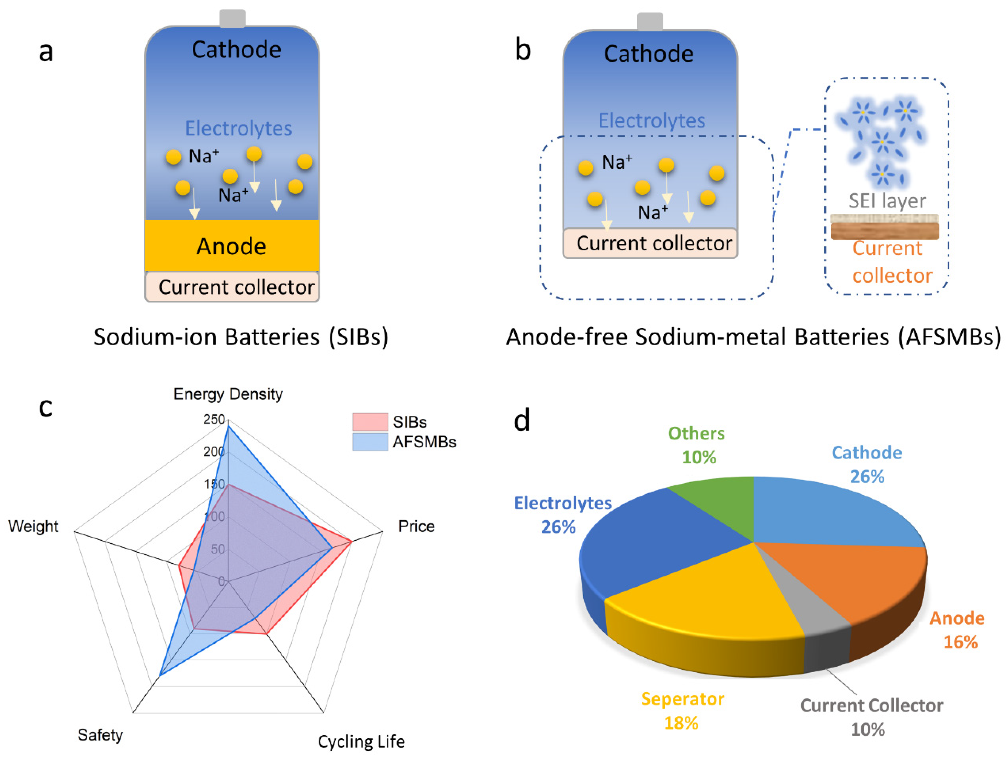
In recent years, with the development and progress of electrolytes and their additives, interface modification technologies, etc., the dendrite problem caused by uneven Na deposition has been significantly alleviated [10,11]. This makes the high energy density sodium-metal batteries (SMBs) possible. To further achieve higher cell energy density, anode-free rechargeable sodium metal batteries (AFSMBs) have also been proposed. Figure 1a,b compares the traditional SIBs and AFSMBs; the difference between these two systems is that there is no additional anode in AFSMBs, whereas the sodium derived from the cathode part deposits on the current collector and acts as the anode. As a result, those conversion-type cathodes are ineligible for AFSMBs. In terms of cell assembly, all the steps are the same for both SIBs and AFSMBs, except that the anode side for the AFSMBs only uses the current collector. During cell operation, the AFSMB cell should be charged first to allow the Na+ deposition on the current collector. In this way, the energy density of the AFSMBs can even be over 200 Wh kg−1. Furthermore, the cell’s total weight can significantly decrease and its portability and safety during transportation are enhanced (Figure 1c). Figure 1d summarizes the cost of each component in SIBs, indicating that sodium-free construction could further lower the price of SIBs by roughly 16%. However, the design of an anode–free electrode leads to a higher overpotential for the deposition of sodium metal on the current collector, which aggravates the uneven metal deposition and the side reactions of the electrolytes. Thus, the active sodium metal is gradually depleted during cycling, which eventually leads to a short circuit of the cell. Since there is no excess sodium in the anode–free cell that can be utilized to compensate for dead sodium, the Coulombic efficiency (CE) of the plating/stripping process is particularly vital, which directly determines the cycle stability of the cell. Despite some advancements over the past several years in the engineering of electrolytes, solid–electrolyte interphase (SEI) layers, and current collectors for AFSMBs, the field has yet to witness a comprehensive review of the developments and cutting-edge technologies of AFSMBs [12].
Future research should focus on developing the electrolyte matching with the AFSMBs, stabilizing the electrochemical interfaces, and developing the appropriate sodium metal deposition current collectors to improve the performance of AFSMBs. However, there is still a lack of understanding and recognition of these aspects. In this review, we revisited the milestone achievements of AFSMBs, including: (i) the optimization of the electrolytes; (ii) the construction of an efficient SEI layer; and (iii) the modification of the current collectors to regulate sodium deposition. In the end, we put forward the challenges and future perspectives regarding the fabrication of AFSMBs.
2. State-of-the-Art Anode-Free Rechargeable Sodium Metal Batteries
2.1. The Optimization of Electrolytes
Electrolytes are carriers that transport charge carrier ions between two electrodes and affect the overall electrochemical reaction during the cycle, which is closely related to battery performance indicators such as cycling life, voltage, and power performances [13]. A good electrolyte for AFSMBs should have the following characteristics: (1) excellent chemical-electrical stability. The optimization of the electrolyte should first consider the corrosion reaction between the sodium metal/current collector with the electrolyte. If high-voltage cathode materials are applied, the electrochemical potential window of the electrolyte, especially the oxidation window, must be taken into account. Other necessary characteristics include: (2) high ionic conductivity and low electronic conductivity; (3) high average sodium plating/stripping CE; (4) good thermal stability; and (5) availability of a salt or solvent to form the SEI.
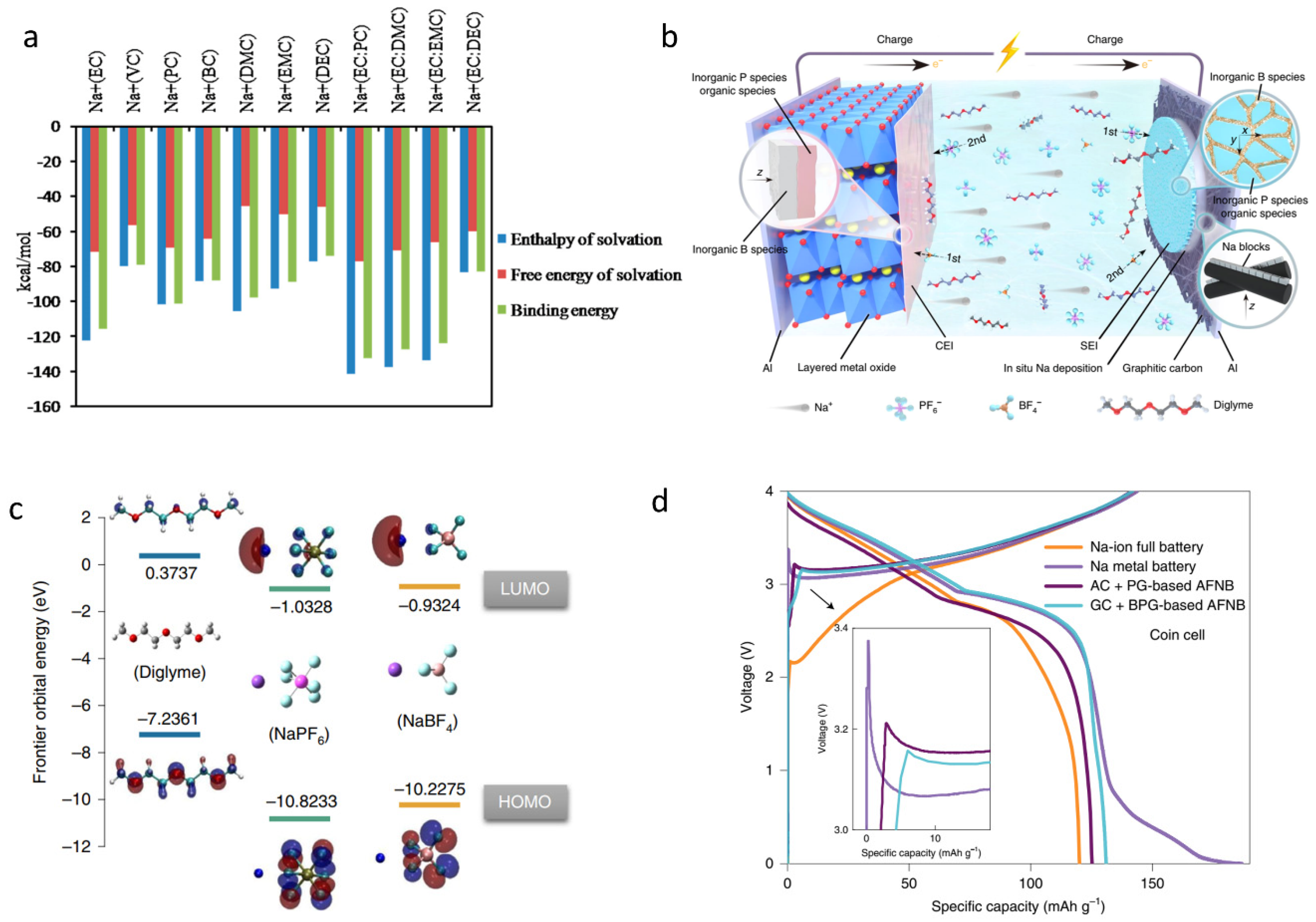
The commonly used electrolytes for SMBs are ester-based or ether-based. Common ester-based solvents include ethylene carbonate (EC), propylene carbonate (PC), diethyl carbonate (DEC), and dimethyl carbonate (DMC) [14]. Among them, EC and PC solvents are attractive organic solvents for SMBs due to their wide electrochemical potential window, large dielectric constant, and good chemical stability. Therefore, binary or ternary carbonate solvents containing EC or PC have attracted the attention of researchers in the application of electrolytes for SMBs. As shown in Figure 2a, EC: PC with Na+ presents the highest binding energy, enthalpy of solvation, and free energy of solvation compared with those of EC: DMC, EC: EMC, and EC: DEC, which demonstrates the suitable choice of binary solvents for SMBs [12]. Furthermore, NaPF6–based electrolytes have the merits of high thermal stability and low cost among various sodium salts. They can form an AlF3 passivation layer on the surface of Al foil to prevent current collector corrosion in electrolytes [15]. Therefore, NaPF6 salt may become the most suitable sodium salt for practical application in AFSMBs.
With the exception of pure solvents, additives have also been proven to affect the formation of the SEI layer, which is connected to the stability of the cell. Shenoy et al. first applied theoretical simulation to study the degradation mechanisms of ethylene carbonate (VC) and fluoroethylene carbonate (FEC) additives in EC solvent and the effect of FEC additives on SEI on the anode surface. Kumar et al. reported that the easy ring opening of the EC molecule will result in continuous SEI growth due to its high reduction potential [16]. The additive of FEC has significantly low barriers compared with EC, therefore, it decomposes prior to the EC. Additionally, the additive molecule increases the energy barrier of EC reduction, thus inhibiting the decomposition of EC. In addition, an additive molecule can regulate SEI components by affecting the reduction path of electrolytes and the preferential reduction state of electrolyte components, which contributes to the formation of a more stable SEI. Unfortunately, the metallic sodium anodes gradually corrode in the carbonate-based electrolytes, resulting in the inferior cycling performances of the AFSMBs [17]. Once the carbonate solvent is complexed with sodium ions, the solvent molecules exhibit a reduced LUMO value, thereby speeding up electrolyte decomposition and gas formation [18,19].
Ether-based electrolytes and ionic liquid electrolytes were suggested as solutions to the aforementioned issues. Ether–based electrolytes have a low viscosity and freezing point when compared with carbonate solvents [20]. Seh et al. first reported an electrolyte compromising NaPF6 and glymes (mono–, di–, and tetraglyme), which delivers highly reversible Na metal plating and stripping; there was an average CE up to 99.9% in a Na-Cu asymmetric cell after 300 cycles. Among the common ether-based solvents, such as 1,2-dimethoxyethane (DME), diethylene glycol dimethyl ether (DEGDME), and triethylene glycol dimethyl ether (TEGDME), the DME presents a relatively low viscosity and volatility. Another study that investigated the transport capabilities of DME and DEGDME solvent–based electrolytes similarly found that the DME–based electrolyte exhibits considerably higher ionic conductivity [21]. Furthermore, a low–impedance SEI could stabilize the metallic sodium when 1 M NaPF6 in diglyme electrolyte was applied, which indicates that the NaPF6 in diglyme electrolytes could be a potential electrolyte for AFSMBs. However, the failure of the cell is typically accelerated by extreme conditions, such as anode-less or anode-free operation, poor cathode material, electrolyte compatibility, and so on [22]. Very recently, Li et al. introduced a second salt of the 0.1 M NaBF4 into the 0.9 M NaPF6 in a diglyme electrolyte [23]. The novel electrolyte with B-containing species enables the formation of both robust SEI and cathode–electrolyte interphase (CEI). The DFT calculation results show that NaPF6 will decompose before NaBF4 at the anode side and NaBF4 will decompose before the NaPF6 at the cathode side due to the higher lowest unoccupied molecular orbital (LUMO) and the highest occupied molecular orbital (HOMO) energy levels of NaBF4 than those of NaPF6. The robust SEI can simplify the Na plating and stripping processes, inhibit the dead Na or Na dendrite accumulation, and prevent the side reactions between the electrolyte and metallic sodium. As shown by the initial charge/discharge profiles in Figure 2d, the AFSMB cell based on the bi-salts electrolyte exhibits the lowest nucleation overpotential and the highest discharge capacity compared with traditional SIBs, SMBs, and amorphous carbon–coated current collector-based anode–free cells. Furthermore, a 200 Wh kg−1 AFSMB was successfully launched with a layered oxide cathode and lean electrolyte. Moreover, the 260 stable cycles were achieved without the extra stack pressure under room temperature.
Figure 2.
Strategies for the optimization of electrolytes. (a) Comparison of the differences in the solvation energies of Na+ with commonly used pure and mixture solvents; [12] copyright 2015 American Chemical Society. (b) A representative AFSMB cell with the layered metal oxide serving as the cathode and the graphitic carbon–coated Al foil acting as the current collector with no Na content at the anode side. The 0.9 M NaPF6 and 0.1 M NaBF4 in diglyme is used as the electrolyte; (c) the calculated LUMO and HOMO values of the diglyme, NaPF6, and NaBF4 salts; (d) The initial discharge/charge profiles of Na-ion battery, Na metal battery, amorphous and graphitic carbon–coated current collector based anode–free cells at a current rate of 0.5 C [23]. Reproduced with the permission of ref. [23], copyright 2022 Springer Nature.

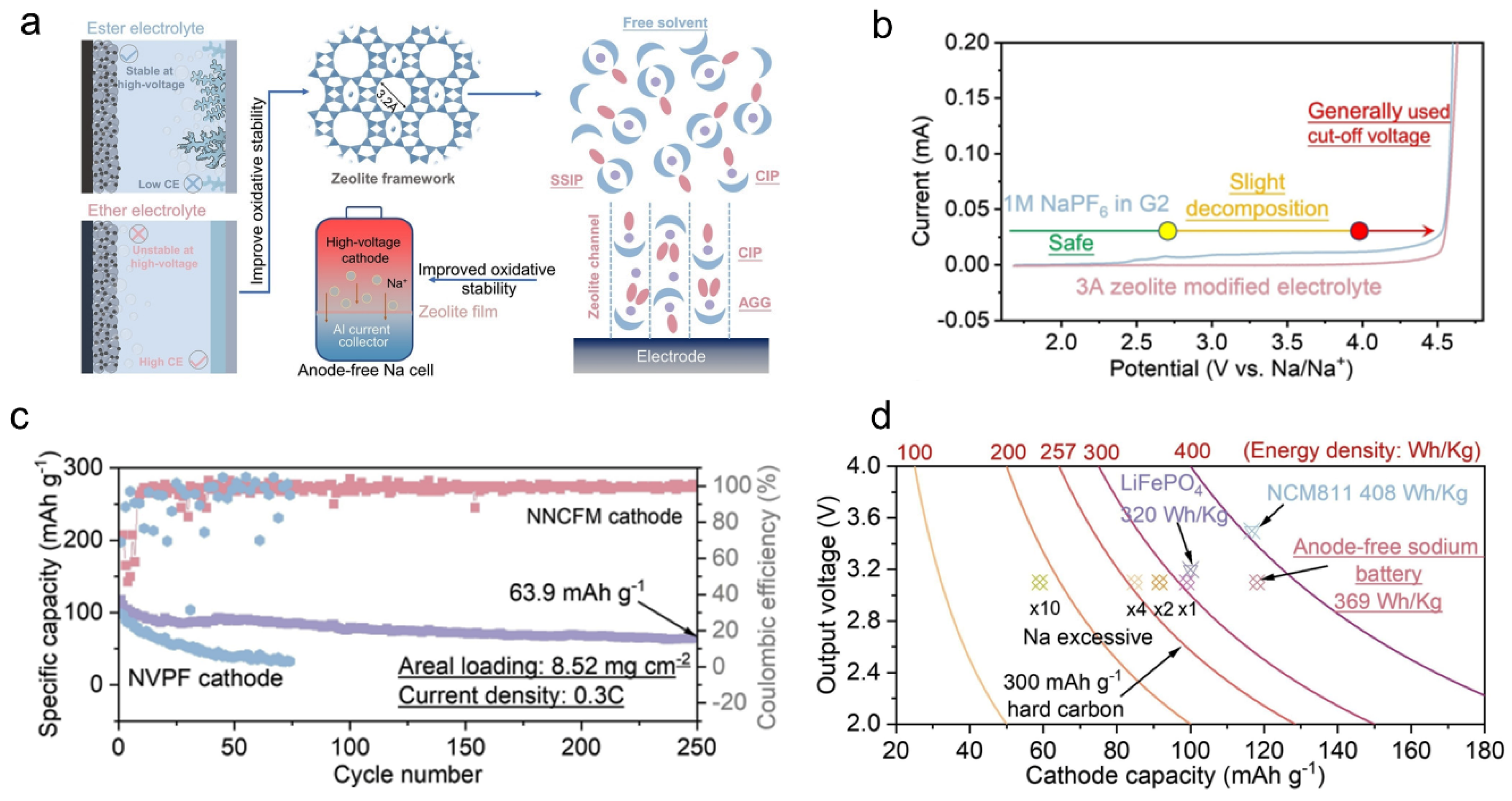
Despite the excellent reversibility for sodium plating/stripping enabled by ether-based electrolytes, the majority of ether-based solvents are unable to support the high-voltage charging process due to their inferior antioxidation properties [24]. To expand the potential window of ether–based electrolytes, strategies such as increasing the concentration of sodium salts [25], or using the zeolite molecular sieve film to regulate the solvation structure have been proven to be viable [26]. The concentration electrolyte has been widely regarded as an appropriate technique to solve the dendrite problem for Li/Na–metal batteries due to their distinctive solvation structures [27,28]. To reduce the cost from the salts, researchers induced an “inert” diluent into the highly concentrated electrolyte (denoted as localized high-concentrated electrolyte), which maintains the original solvation structure of cation–anion aggregates [29]. Such a method also works for sodium–metal batteries. For instance, a localized high–concentrated electrolyte, i.e., 2.1 M NaFSI with DME and bis(2,2,2–trifluoroethyl) ether (BTFE) (the molar ratio is 1:2) could enable a dendrite-free Na plating/stripping CE as high as 99% in the Na/Cu cell [25]. To further reach the high reversibility of Na plating/stripping processes while expanding the oxidative stability, Lu et al. rationally designed a beyond–concentrated electrolyte by a 3A zeolite molecular sieve film [26]. As shown in Figure 3a, a high-voltage AFSMB is built by coating a zeolite film on the Al current collector, where the free solvent in the pure diglyme-based electrolyte will be optimized through the zeolite channels. In this way, the electrolyte in the zeolite reaches a limited state where almost no free solvent exists in the electrolyte. As a result, the electrolyte enables an oxidative stability potential as high as 4.5 V (vs. Na/Na+) identified by the linear sweep cyclic voltammetry (LSV) test (Figure 3b). An extremely high average Na plating-stripping CE of 99.91 % is obtained after 320 cycles (current density: 1 mA cm−2, areal capacity of 1 mAh cm−2). In particular, a 73.1% capacity is still present after 250 cycles in an anode–free cell made up of a NaCu1/9Ni2/9Fe1/3Mn1/3O2 cathode and the zeolite-modified electrolyte (Figure 3c). The specific energy density of the 1 Ah level anode–free cylindrical cell with Na[Cu1/9Ni2/9Fe1/3Mn1/3]O2 as the cathode is up to 205 Wh kg−1, which is even higher than that of the commercialized LiFePO4-graphite LIBs (~180 Wh kg−1) and up to 60% higher than the cell with the hard carbon anodes (Figure 3d).
Ionic liquid has the characteristics of high conductivity, non-volatilization, non-flammability, and wide electrochemical potential window compared with other liquid electrolytes [30]. Ionic liquid electrolytes are therefore frequently employed as electrolytes in high-performance batteries [31]. Rahmat et al. first investigated the electrochemistry behaviors between sodium metal and ionic liquids, revealing that lithium and sodium have comparable thermodynamic electrochemical potentials [32]. This demonstrates that the SMBs could potentially reach a similar high voltage to that of LMBs when a suitable cathode is applied. Based on the above understanding, Sun et al. found that a chloroaluminate-based ionic liquid electrolyte (NaCl-buffered AlCl3/[EMIm]Cl) enables a full cell outputting a high voltage up to ~4 V, which comprises a sodium vanadium phosphate fluoride (NVPF) cathode and sodium metal anode [33]. Furthermore, this optimized electrolyte is non–flammable and highly conductive, delivering the full cell with a high CE of up to 99.9%. Although the authors did not apply it in an anode–free cell, the high CE also indicates that the electrolyte is a good candidate for AFSMBs. However, ionic liquid electrolytes do have certain drawbacks, including a high viscosity at room temperature, a high degree of hygroscopicity, and a somewhat costly price at the moment [34]. All of these pose significant obstacles to the industrialization of the use of ionic liquids [35].
2.2. The Construction of an Efficient SEI Layer
According to the previous discussion, low CE value and dendrite Na deposition are the two critical challenges faced by AFSMBs. These two problems are the results of the interface chemistries between electrolyte-sodium or metal-current collectors. Therefore, optimizing the interfacial chemistry plays a decisive role in solving the dendrite problem and improving CE [36,37]. The fabrication of a stable SEI for AFSMBs can be classified into in situ formed SEI and artificial SEI methods [38,39]. The in situ method is realized by controlling the electrolyte salts, additives, or solvents. In contrast, the artificial approach typically uses an artificial layer with strong mechanical strength and flexibility to prevent contact between the sodium metal and electrolyte. Additionally, the artificial SEI’s composition and structure can be regulated to meet specific needs. In the electrochemical reaction, the redox reactions are usually carried out within the electrochemical stability potential window (ESW) of the electrolyte. According to the frontier molecular orbital theory, the stability window is controlled by the LUMO and the HOMO [40,41]. Most electrolyte components, including solvents, salts, and additives, have a tendency to be reduced on the anode part during the Na plating process and create an SEI layer due to the low standard potential of the Na/Na+ (−2.76 V). Such a passivation film can block the continuous electrolyte reaction and increase the overpotential of electrolyte decomposition, leading to the expansion of the ESW of the electrolytes. Therefore, an understanding of the SEI composition and protection mechanism can help us to design a robust SEI layer for the AFSMBs.
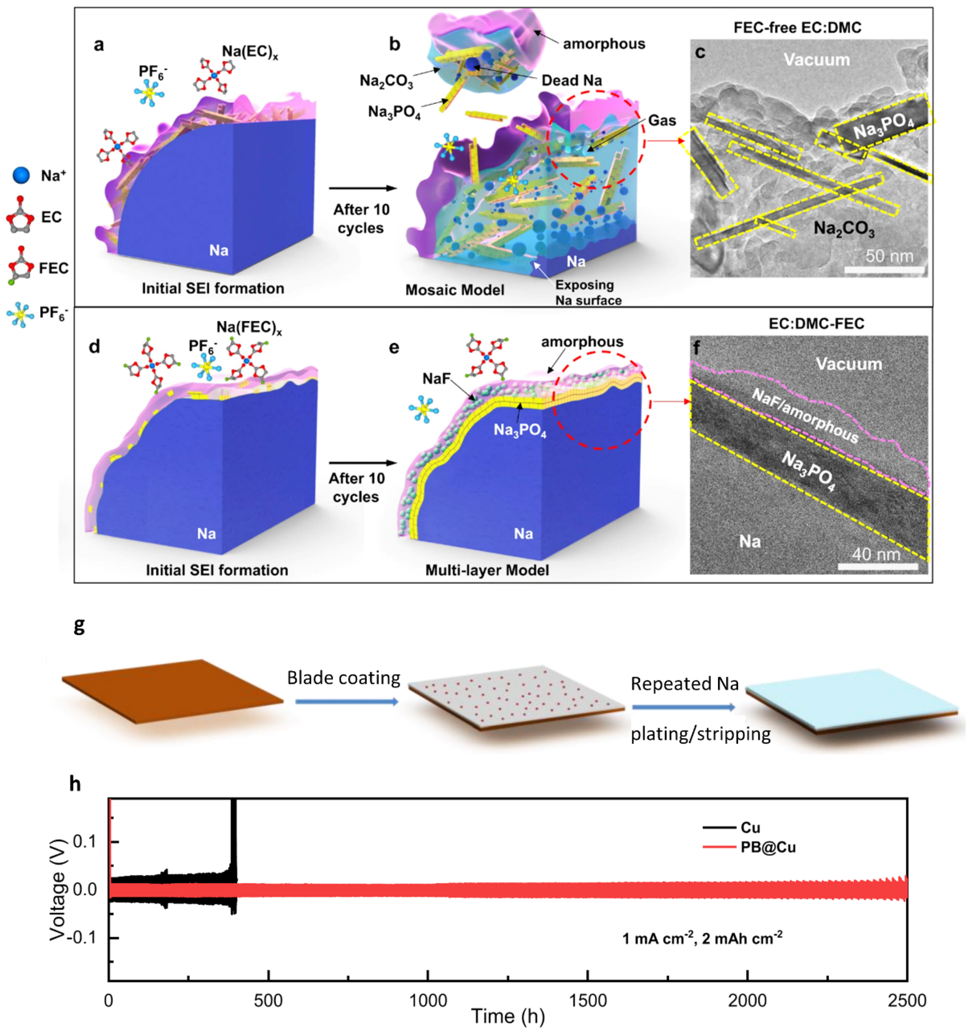
The use of some additives, such as FEC, has been reported to enhance the cycling stability of the SMBs for a long time [42,43]. However, the chemical and morphological behavior of the SEI layer with the electrolyte was still unknown until the employment of cryogenic transmission electron microscopy (cryo–TEM) [44]. Cryo–TEM has been reported to be an inevitable tool to preserve the native state of sensitive materials and interphases while performing high-resolution imaging [45,46]. Han et al. reported via the cryo-TEM that in NaPF6 FEC–free EC: DMC-based electrolyte, the electrolyte tends to react with the Na metal due to the higher electron affinity of EC than DMC [44]. The compositions of formed SEI are rich in Na2CO3 and Na3PO4. During the following cycles, the Na2CO3 will decompose to CO2 and further damage the SEI layer. As a result, the deposited Na metal will be exposed to the electrolyte and further react with the electrolyte (Figure 4a–c). As a contract, the added FEC solvent will react with the sodium metal to form a thin layer of amorphous NaF in the NaPF6 FEC–free EC: DMC-based electrolyte system, which can anchor on the top of the initially formed Na3PO4 layer to a NaF-Na3PO4 multi–layer (Figure 4d–f). The Na/Na symmetric cell shows that the cell with the FEC additive maintains a 500 to 800 h cycling performance at the current density from 0.5 to 2 mA cm−2, whereas the cell without the FEC additive shows an instant increase of the overpotential only after 50 cycles at 0.5 mA cm−2 and a catastrophic cell failure at 2 mA cm−2.
Artificial SEI is an attractive solution to overcome the inherent shortcomings of the SEI layer [48]. Since the artificial SEI is constructed outside the battery, the composition, thickness, and mechanical properties of the interphase can be precisely designed. Furthermore, the morphology of the deposited sodium metal can be precisely controlled due to the tunable SEI layer [49,50]. According to the previous studies, the design of a stable artificial SEI should follow three principles: (i) it can effectively block the reaction between the electrolyte and sodium metal; (ii) it has good ionic conductivity, allowing smooth ion transportation including single ions; and (iii) it has good mechanical stability and can withstand repeated deposition and stripping processes of the sodium metal. At present, various inorganic– or organic–based artificial SEI have been reported for sodium metal batteries, including graphene [51], polyvinylidene fluoride (PVdF) [52], metal–organic framework materials [53], carbon nanotube paper [54], metal oxide layer, and some alloy-based artificial layers [55,56].
Unlike the SMBs with excess sodium metal, the artificial SEI for AFSMBs should be fabricated on the current collector. Therefore, an additional sodiophilic media is typically included in the protective layer. For instance, Zhang et al. reported that a composite SEI layer compromising the PVdF and Bi powder (referred to PB@Cu) can serve as an effective artificial protective layer for the AFSMBs [47]. The authors also demonstrated that Bi in the artificial SEI can alloy with the sodium to form Na3Bi during the first deposition process. Along with directing the sodium ion flux, the Na3Bi can help strengthen the mechanical properties of the film. In addition, the flexible PVdF can sustain the volume expansion during the sodium plating/stripping cycles as well as promote the formation of NaF–rich SEI. The following Na plating/stripping CE test shows that the cell with the PB@Cu optimized current collector outputs a high average CE of 99.92% after 2500 cycles. The cell with a bare Cu current collector, in contrast, is only capable of providing cycling performance for about 400 h. Moreover, the AFSMB cell with the Na3V2(PO4)3 cathode/PB@Cu exhibits 150 stable cycles.
Although numerous intriguing approaches such as artificial and in situ SEI have been proposed and show promising results, these methods still lack competitive results when a full cell is fabricated. In addition, the current work tends to apply ether–based electrolytes rather than ester–based electrolytes to build the in situ SEI layer, which inevitably sacrifices the electrochemical potential window of the electrolytes. Furthermore, researchers still lack a thorough understanding of the active components of the SEI for SMBs, and they take it for granted that the introduction of F into the electrolyte is indispensable. However, there have been several studies indicating that the development of fluorine–free electrolytes is beneficial for stable sodium metal deposition and stripping, as well as the subsequent formation of a stable SEI layer [57,58].
2.3. Modification of the Current Collectors to Regulate Sodium Deposition
As discussed in the electrolyte section, certain strategies for resolving the problems of continuous SEI growth have been developed, such as the introduction of ether-based electrolytes or concentrated electrolytes [59]. However, the issues concerning the interface between the sodium metal and the current collector, as well as the volume expansion of the deposited sodium metal still necessitate attention for the AFSMBs. During the sodium plating process, the current collector influences the initial nucleation conditions and the subsequent sodium deposition growth [60,61]. Therefore, the modification of the interface of the current collector helps to improve the morphology of metallic sodium deposition, while a 3D hierarchical host can alleviate metal volume expansion and allow rapid Na-ion flux [62]. The current collector engineering strategies can be divided into three categories, including: (i) constructing a sodiophilic interface on the current collector; (ii) designing a 3D hierarchical host; and (iii) fabricating a sodiophilic multi-alloy to guide Na deposition. In contrast to an insertion anode, an energetic sodium nucleation layer can minimize sodium loss and maximize cycle life [63]. It is critical to remember when designing the nucleation layer that the mass loading of the nucleation layer should not limit the battery’s capacity. In other words, the addition of the nucleation layer has no significant effect on the cell’s voltage and energy density.
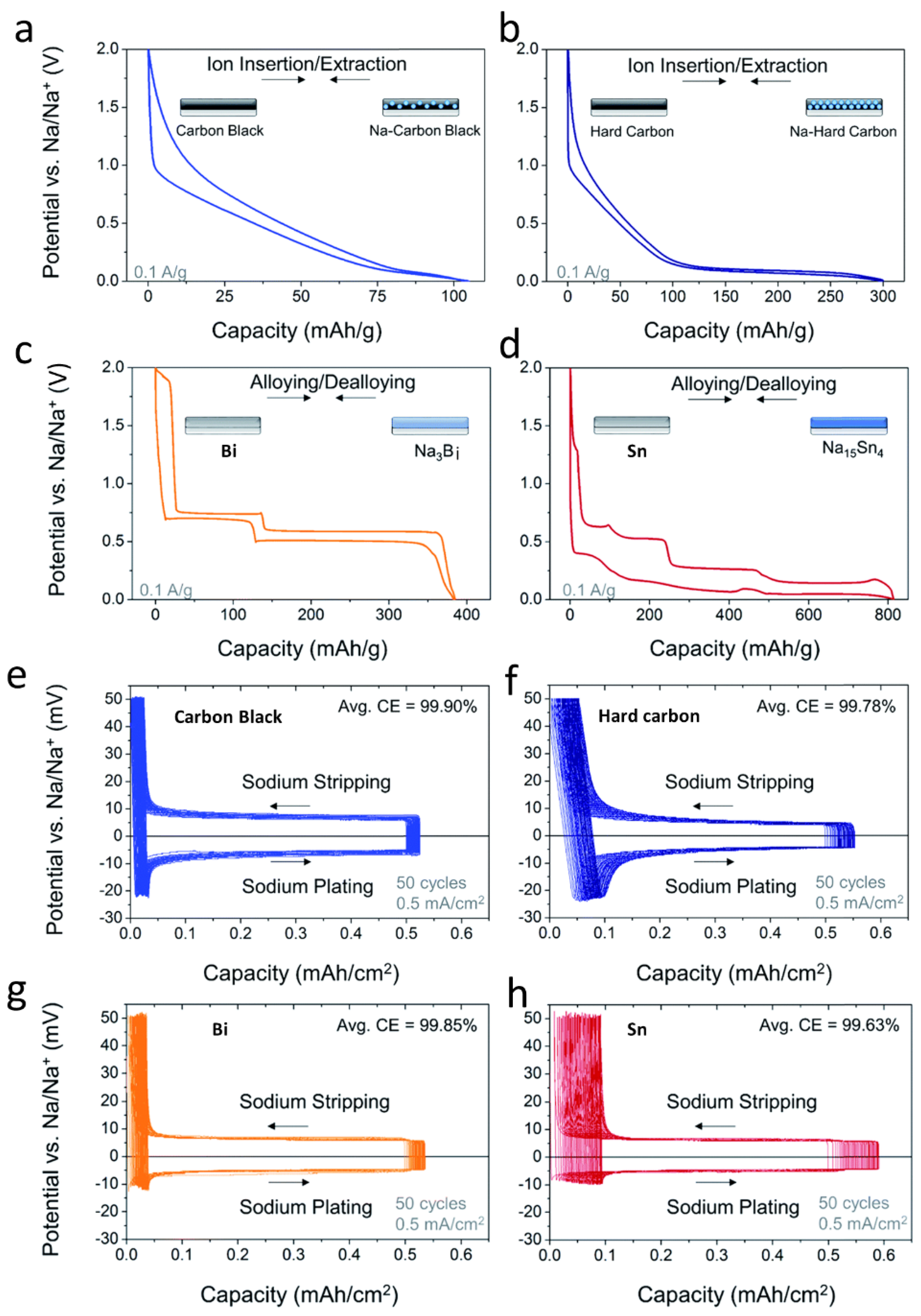
To understand how the nucleation layer impacts sodium plating–stripping, Cohn et al. investigated four different nucleation layers for sodium plating, including non-graphitized carbons such as carbon black and hard carbon, and sodium–alloying metals such as bismuth and tin to guide the sodium metal deposition [63]. According to their sodium-ion storage properties (Figure 5a–d), the carbon black and the bismuth electrodes exhibited significantly lower capacities than those of hard carbon and tin. Figure 5e–h showed the plating–stripping profiles during 50 cycles performed on the corresponding four electrodes, where the differences in the starting and ending point after 50 cycles indicate the cumulative loss of charge. The findings show that for carbon black and bismuth electrodes, the predicted sodium plating-stripping CE can reach 99.9% and 99.85%, respectively. The authors demonstrate that the deposition of sodium metal in a high surface area/volume ratio nucleation layer, corresponding to a lower nucleation overpotential and a smaller nucleation size, leads to more serious electrolyte side reactions with deposited sodium metal. Subsequently, an anode-free cell was also evaluated by selecting carbon black on Al foil as the anode, 1 M NaPF6 in diglyme as the electrolyte, and Na3V2(PO4)3 as the cathode. The cell showed a capacity retention of 82.5% after 100 cycles and an average roundtrip energy efficiency above 98%.
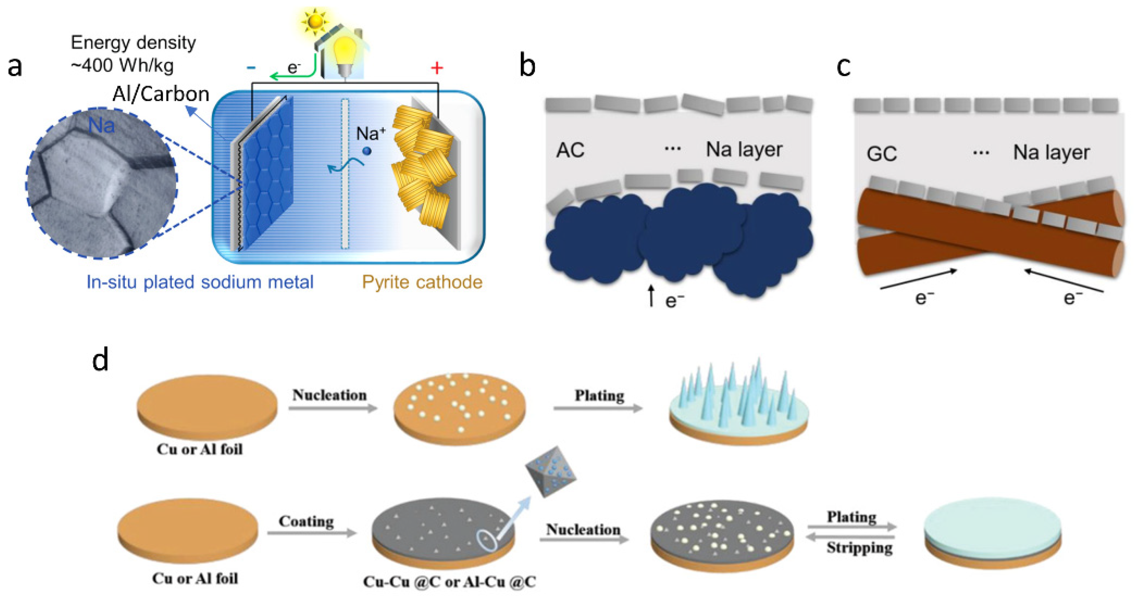
Based on a comprehensive understanding of the relationship between the properties of the sodium nucleation layer and the plating–striping CE, researchers tend to explore various nucleation layers such as the nanocarbon nucleation layer formed on Al current collectors [64], metal–organic frameworks (MOF)-derived copper-carbon (Cu@C) composite [65], or graphitic carbon–coated current collectors [23]. For instance, a nanocarbon nucleation layer (conductive carbon black, TIMCAL Super C45)–coated Al current collector could simplify the sodium seeding process with a lower nucleation energy barrier (Figure 6a) [64]. Electrochemical analyses revealed that at a current density of 0.5 mA/cm−2 with loading up to 0.25 mAh/cm−2, a sodium plating/stripping CE of 99.8% on average over 1000 cycles was accomplished. Such a remarkable performance should be attributed to the high surface area of the porous carbon black, the oxygen-containing functional groups with active sp3 carbon sites. In terms of the nucleation layer affecting the morphology of sodium depositions, Li et al. argued that the initial Na nucleation on the current collector dictates the subsequent deposition processes [23]. They selected two distinct current collectors, respectively made of amorphous and graphitic carbon–coated aluminum foil (Figure 6b,c). While the Na‖GC cell displays both sloping and plateau areas with minimal initial capacity loss, the Na‖AC cell exhibits a sloping characteristic with a substantial initial capacity loss. Moreover, it can be shown from the over-discharge profiles that the Na‖GC cell undergoes a smaller sodium metal nucleation overpotential than that of the Na‖GC cell, which could be advantageous for the Na deposition on the sodiophilic and ordered carbon surface. In addition to the carbon-based nucleation layer, the MOF-derived nanocomposites also showed effectiveness in guiding sodium deposition. Very recently, Li et al. reported that a novel metal-organic frameworks–derived Cu@C composite can be a reliable sodiophilic layer for sodium metal deposition [65]. The findings showed that the carbon structure with a large surface area could accommodate the sodium’s overall volumetric expansion during repeated plating/stripping procedures. Compared with the bare Cu or Al current collector, such a modified sodiophilic current collector effectively decreases the nucleation barrier, thus leading to excellent performances (Figure 6d). In the Na‖Cu–Cu@C asymmetric cell at 0.5 mA cm−2 and 1 mA h cm−2, nearly 1600 h (average CE of 99.9%) and 1200 h (average CE of 99.8%) cycling life was achieved, significantly superior to that of the bare Na‖Cu cell.
Another strategy to optimize the current collector is to construct a 3D hierarchical host for the sodium metal anode. In order to address the dendritic concerns in metal batteries, 3D current collectors have been widely used. The porous structure and sodiophilicity are two key parameters that affect the performances of the 3D current collectors. The sand’s time τ describes the time when sodium dendrite begins to grow, which can be expressed by sand’s equation [66]:
where D is the ambipolar diffusion coefficient, e is 1.60217662 × 10⁻¹⁹ C, J is the Faradaic current density, C0 is the initial sodium-ion concentration, and μa and μc represent the anion and cation mobility, respectively. According to sand’s equation, the local Faradaic current density decreases because the high porosity current collectors disperse the charge due to their large surface areas. As a result, the formation rate of the sodium dendrites will be slowed down. In addition, the 3D porous structure also reduces the volume expansion of the plated sodium metal [67]. Considering the energy density and mechanical properties of the battery, the density of the current collectors should be light and should have excellent mechanical properties [68]. In terms of the constructing methods for 3D current collectors, many similar methods have been reported on LMBs, including template methods, electrostatic spinning, dealloying methods, and 3D printing. There are different kinds of structures that have been reported, such as gradient structure, Janus structure, foam, interweaved structure, and array structure [69,70,71,72,73].
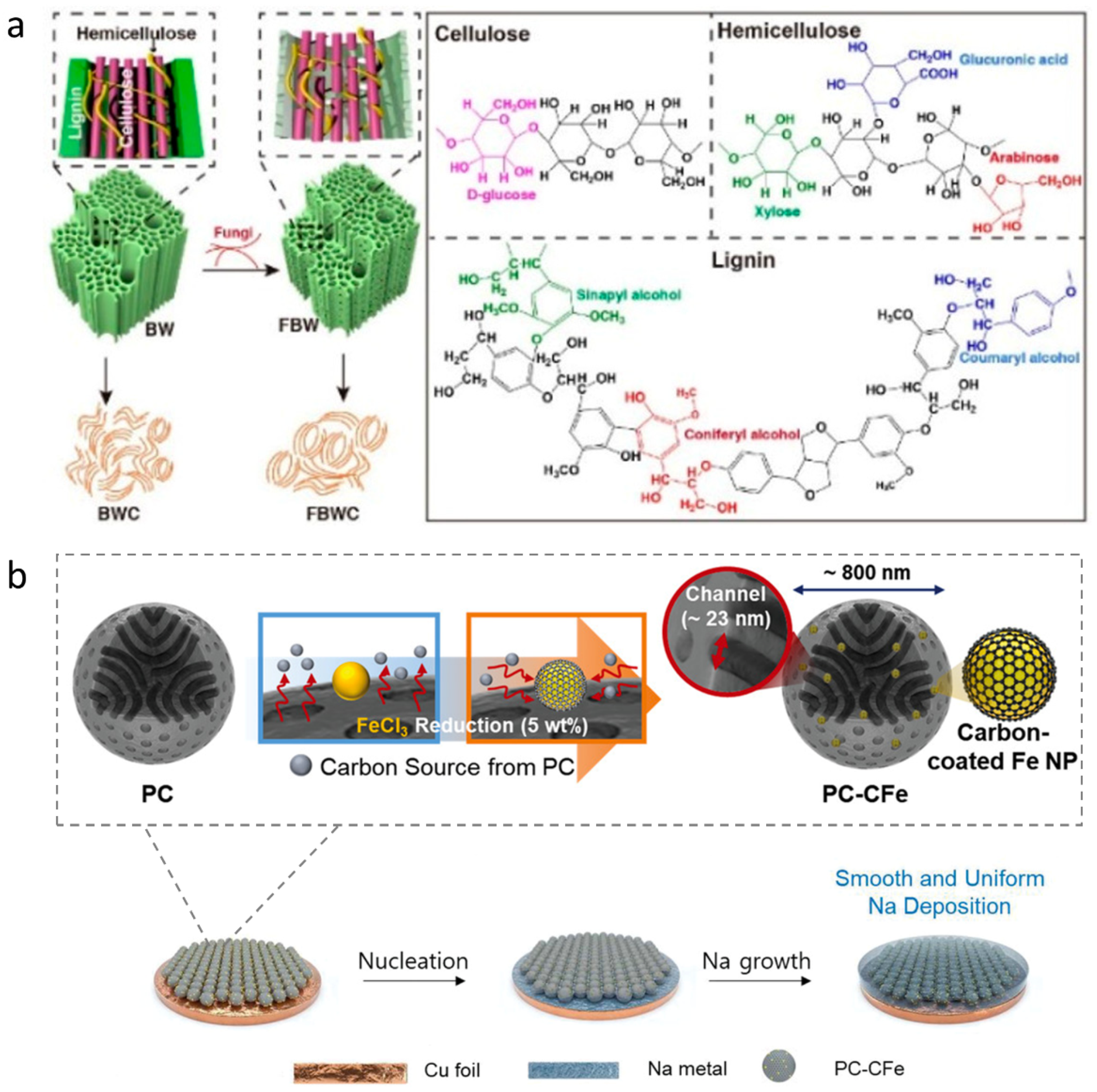
Wang et al. reported a lightweight 3D carbon current collector derived from a fungi–assisted biosynthetic approach [74]. One advantage of carbon–based current collectors compared with metallic current collectors is their light weight. As illustrated in Figure 7a, the authors first inoculated basswood with fungi and selectively etched large lignin skeletons through the oxidation reaction of hydroxyl radicals produced by fungi using the Fenton chemistry reaction [75]. This fungus–treated basswood (FBW) can be converted into a self-supporting carbon electrode (FBWC) with a short–range ordered graphite structure after thermal treatment. More importantly, the prepared carbon current collector has vertically aligned channels and high porosity, leading to a decreased local density and uniform sodium deposition. The sodium/FBWC asymmetric cell exhibits a stable sodium plating/stripping for more than 4500 h at a high area capacity up to 10 mAh cm−2 and a high average CE of 99.5%. Although the authors did not show the full cell performance, this work shed light on the interesting idea of biomass–derived carbon materials as 3D current collectors for AFSMBs.
Except for constructing a pure 3D current collector, some sodiophilic metal nanoparticles such as Au, Ag, and Sn have also been introduced to guide the initial sodium nucleation [77,78,79,80,81]. For instance, the 3D PC–CFe nanoparticles were selected as a highly reversible host for AFMBs [76]. As shown in Figure 7b, the PC–CFe host is fabricated by the carbonization of super–cross-linked colloidal particles of nanostructured block copolymers (BCPs), during which Fe-metal precursors are reduced to ultra-thin carbon-coated Fe nanoparticles (NPs). The synthesized PC–CFe host presents ordered open channels with a diameter of ~23 nm. Such a unique 3D hierarchical structure is beneficial for the initial Na nucleation within the open channels, leading to an even Na+ flux and the final smooth Na deposition. Na plating/stripping cycle tests showcased that the Na plating/striping was able to last for 1500 cycles (6000 h, 2 mAh cm−2) with a CE of 99.9% and 1200 cycles (4800 h, 8 mAh cm−2) with a CE of 99.8%, respectively. The anode–free full cells with a high mass loading of Na3V2(PO4)3 cathode (~10 mg cm−2) maintain a 97% capacity retention after 100 cycles.
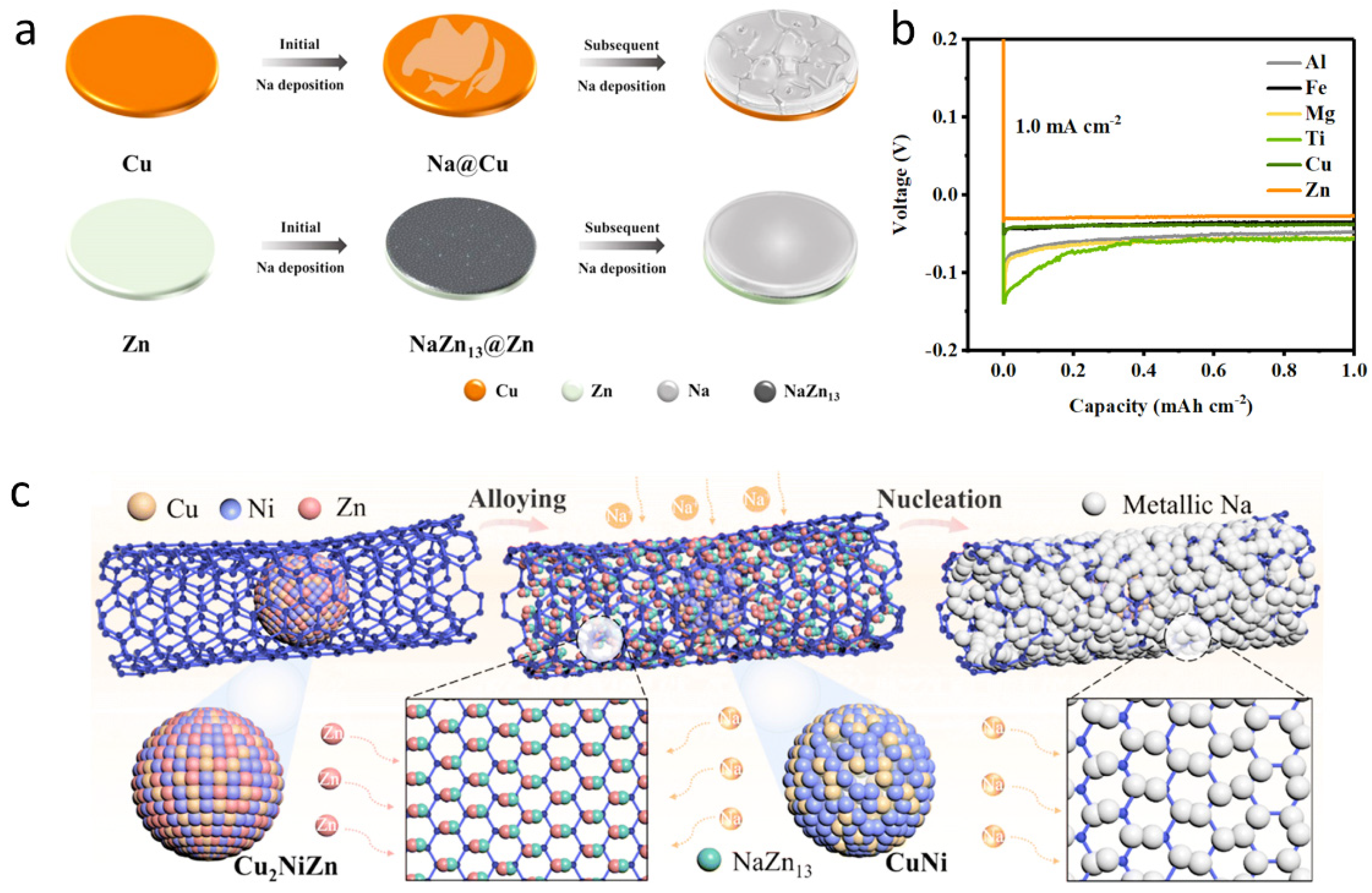
Regarding the method of fabricating a sodiophilic multi-alloy to guide Na deposition, it has been widely accepted that alloying strategies enable the homogenous distribution of sodiophilic sites. Various alloying strategies have been employed, such as Na–Sn, Na–Au, Na–In, and Na–Sb [47,77,82,83]. Liu et al. proposed that zinc (Zn) foil could be directly used as the current collector to load deposited sodium metal [84]. As illustrated in Figure 8a, a sodiophilic alloy of NaZn13 formed on the top of the zinc foil after the initial Na deposition. The results show that the nanoscale NaZn13 interface can significantly reduce the deposition overpotential of sodium metal and induce uniform and dense deposition of Na, thus improving the cycling stability and average CE of the Na metal anode. Furthermore, the nucleation overpotential profiles show that Zn foil stands out in Al, Fe, Mg, Ti, and Cu foils, indicating excellent sodiophilicity with sodium (Figure 8b). Although this work constructs a promising sodiophilic alloy, their following cycling performance is still unsatisfactory. There are two unresolved issues. One is the initially formed sodiophilic alloy cannot maintain its structure upon cycling; the volume expansion would result in the detachment from the current collector [85]. In addition, the exposure of the alloy in the electrolyte does not solve the problem of the side reaction between the electrolyte and anode [86]. Guided by theoretical simulations and real-time phase evolution, Bai et al. designed a series of mechanically flexible and ultralight medium/high–entropy alloys within the carbon nanotubes framework, i.e., Cu2NiZn@CNT, FeCoNiZn@CNT, and FeCoNiAlZn@CNT, acting as the sodium deposition current collectors (Figure 8c) [87]. Among them, the Cu2NiZn@CNT current collector shows the lowest sodium deposition overpotential. As illustrated in Figure 6c, during the sodiumization process, the sodiophilic Zn atoms are extracted from the cubic Cu2NiZn and anchored on Na+ to form the NaZn13 alloy. The NaZn13 alloy migrates according to the concentration gradient. The uniform distribution and diffusion of sodiophilic sites inside CNTs can theoretically maximize the Na affinity of CNT scaffolds while avoiding particle agglomeration, volume expansion, and direct contact corrosion with electrolytes.
3. Summary and Perspective
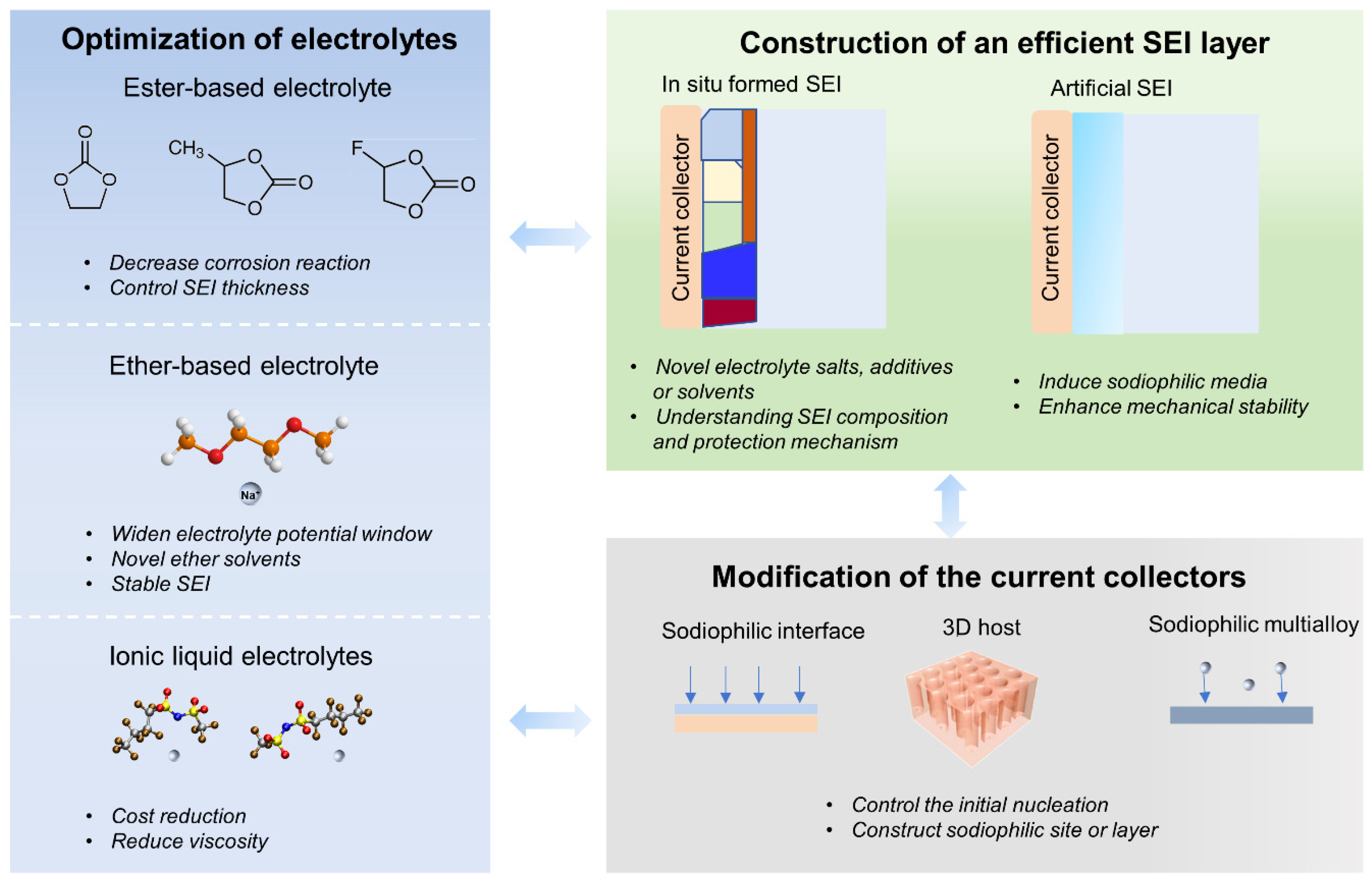
In this review, we summarized the signs of progress of AFSMBs, focusing on the optimization strategies of the electrolytes, interfaces, and current collectors. Figure 9 summarizes the objectives of this review article, which also presents the current strategies concerning electrolyte chemistry, SEI, and current collectors. In the electrolyte section, we comprehensively compared the development of ester–based or ether-based electrolytes. It is important to note that pure carbonate solvents tend to react with sodium metal. As a result, when using ester–based electrolytes in AFSMBs, film-forming chemicals are required to stabilize the pure carbonate solvents. In particular, the sodium-based electrolytes can benefit from the PC’s high permittivity and reduced melting and higher boiling points, while boosting SEI growth with minimal amounts of cosolvents or additives. This is beneficial to the development of electrolytes with comprehensive performances. In addition, the corrosion reaction of the fluorinated solvents, salts, and additive electrolytes with sodium metal anodes has sparked renewed interest in non–corrosive electrolytes for AFSMBs. An alternative option is to utilize an ether–based electrolyte or an ionic liquid electrolyte. We also emphasized that the ether-based electrolyte design should consider the electrolyte potential window, especially for those high-voltage cathodes. Strategies such as concentrated electrolytes or localized concentrated electrolytes are options for addressing this concern. Ionic liquid electrolytes have also been widely used for SMBs. However, there are currently few relevant references reported for AFSMBs. In the future, strategies on the electrolytes for AFSMBs may be divided into three major categories: (i) the development of novel ether–based electrolytes; (ii) quantifying the capacity loss mechanism of the inactive sodium metal; and (iii) paying special attention to the electrolyte operating temperature.
The nature of SEIs in AFSMBs were also introduced in terms of the in situ formed SEI and the artificial SEI. We mentioned that the SEI layer can be designed by regulating the sodium salts, additives, solvents, and concentration of the electrolytes. The carbonate electrolyte tends to react with the sodium metal, so we should particularly pay attention to this when selecting the carbonate solvents. Some additives are strongly recommended for the formation of a passivation film to protect the deposited sodium metal. Because of their adjustable physical and chemical components, artificial SEI layers are also of great concern. Given the lack of sodium metal on the anode side, sodiophilic sites should be incorporated into the design of the artificial SEI layer. Other fundamental principles in designing the artificial SEI for AFSMBs are likewise summarized into three points in our context. An important point that has not yet been addressed is that researchers need to reconsider the fundamental differences between constructing artificial SEI layers on a current collector and on a sodium metal anode or hard carbon anode. In particular, SEI stability in the AFSMBs necessitates special consideration. It should be noted that ongoing research on the SEI layer is still relevant. There is still a long way to go in understanding the formation mechanism, structure, and composition of SEIs in AFSMBs. To trace the SEI in their native states to overcome the limitations of the ex situ techniques, more in situ characterization methods, particularly for electron microscopy and spectroscopy, are highly suggested to investigate the formation mechanism during cell operation. In addition, some nondestructive technologies could be powerful tools for operando dynamic visualizations, including cryo–TEM, differential electrochemical mass spectrometry (DEMS), electrochemical quartz crystal microbalance (EQCM), and in situ Raman spectroscopy.
Finally, we reviewed the state-of-the-art current collectors for AFSMBs, which were summarized in three directions, including introducing a sodiophilic interface on the current collector, designing a 3D current collector, and constructing a sodiophilic multi-alloy as a novel current collector. In this section, we emphasized the crucial role of initial nucleation on the morphology and plating/stripping stability of the sodium metal deposition. By comparing the several carbon–based layers and the sodiophilic layers, we demonstrated the merits of the non–graphite carbon and sodiophilic metal for optimizing the current collectors. Furthermore, the light weight of the carbon-based current collectors can significantly decrease the overall weight of the cell, thus maximizing the energy density. Further work related to the current collector is highly suggested to elucidate the relationship between the physical/chemical properties of the nucleation layer and Na deposition behaviors. For instance, how might surface chemistry, pore size, and defects influence nucleation and subsequent plating/stripping behaviors?
Although the anode-free design can significantly reduce the side reactions or safety risks associated with transportation and corrosion of sodium metal anodes during calendar aging, it does not completely eliminate the safety considerations during Na transport through separators and deposition onto collectors. As we all know, the dendrite growth inevitably leads to the destruction of the separators and ultimately results in the short circuit of the cell. Therefore, some factors should be considered, including: (1) the mechanical strength of the separators. For instance, a flexible film can withstand the attack of sodium dendrites. Another factor is to (2) regulate the ideal state for storage/shipping of AFSMBs. It has been reported that the ultimate safety condition for a rechargeable sodium battery system is at 0 V or zero energy. The third factor is (3) the choice of a fire-extinguishing current collector.
We believe that combining electrolyte, interface, and current collector strategies will eventually bring us closer to high energy and long–life AFSMBs for energy storage systems or power batteries. The strategies proposed in the present work, such as electrolyte optimization, interfacial chemistry engineering, and current collector modification, are also expected to be referenced by other anode-free rechargeable batteries such as Li, Mg, and Al batteries.
Author Contributions
Conceptualization, Q.N. and G.S.; software, Q.N.; validation, G.S., L.L. and M.Y.; formal analysis, Y.Y.; investigation, Z.S.; writing—original draft preparation, Q.N.; writing—review and editing, Y.Y., H.D. (Haoshen Du), H.D. (Hao Deng). and J.L.; supervision, G.S.; funding acquisition, Q.N. All authors have read and agreed to the published version of the manuscript.
Funding
This work is financially supported by the Beijing Normal University (no. 310432107).
Data Availability Statement
Not applicable.
Conflicts of Interest
The authors declare no conflict of interest.
References
- Yabuuchi, N.; Kubota, K.; Dahbi, M.; Komaba, S. Research development on sodium-ion batteries. Chem. Rev. 2014, 114, 11636–11682. [Google Scholar] [CrossRef] [PubMed]
- Pan, H. Room-temperature stationary sodium-ion batteries for large-scale electric energy storage. Energy Environ. Sci. 2013, 6, 2338–2360. [Google Scholar] [CrossRef]
- Grey, C.P.; Hall, D.S. Prospects for lithium-ion batteries and beyond—A 2030 vision. Nat. Commun. 2020, 11, 6279. [Google Scholar] [CrossRef] [PubMed]
- Zhu, Y.; Gao, T.; Fan, X.; Han, F.; Wang, C. Electrochemical Techniques for Intercalation Electrode Materials in Rechargeable Batteries. Acc. Chem. Res. 2017, 50, 1022–1031. [Google Scholar] [CrossRef]
- Winter, M.; Barnett, B.; Xu, K. Before Li Ion Batteries. Chem. Rev. 2018, 118, 11433–11456. [Google Scholar] [CrossRef]
- Hwang, J.Y.; Myung, S.T.; Sun, Y.K. Sodium-ion batteries: Present and future. Chem. Soc. Rev. 2017, 46, 3529–3614. [Google Scholar] [CrossRef] [Green Version]
- Yang, M.; Luo, J.; Guo, X.; Chen, J.; Cao, Y.; Chen, W. Aqueous Rechargeable Sodium-Ion Batteries: From Liquid to Hydrogel. Batteries 2022, 8, 180. [Google Scholar] [CrossRef]
- Peters, J.; Peña Cruz, A.; Weil, M. Exploring the Economic Potential of Sodium-Ion Batteries. Batteries 2019, 5, 10. [Google Scholar] [CrossRef] [Green Version]
- Choi, J.W.; Aurbach, D. Promise and reality of post-lithium-ion batteries with high energy densities. Nat. Rev. Mater. 2016, 1, 16013. [Google Scholar] [CrossRef] [Green Version]
- Zhu, M.; Wang, G.; Liu, X.; Guo, B.; Xu, G.; Huang, Z.; Wu, M.; Liu, H.K.; Dou, S.X.; Wu, C. Dendrite-Free Sodium Metal Anodes Enabled by a Sodium Benzenedithiolate-Rich Protection Layer. Angew. Chem. Inter. Ed. 2020, 132, 6658–6662. [Google Scholar] [CrossRef]
- Gao, L.; Chen, J.; Chen, Q.; Kong, X. The chemical evolution of solid electrolyte interface in sodium metal batteries. Sci. Adv. 2022, 8, eabm4606. [Google Scholar] [CrossRef]
- Shakourian-Fard, M.; Kamath, G.; Smith, K.; Xiong, H.; Sankaranarayanan, S.K.R.S. Trends in Na-Ion Solvation with Alkyl-Carbonate Electrolytes for Sodium-Ion Batteries: Insights from First-Principles Calculations. J. Phys. Chem. C 2015, 119, 22747–22759. [Google Scholar] [CrossRef]
- Zhang, J.-G.; Xu, W.; Xiao, J.; Cao, X.; Liu, J. Lithium Metal Anodes with Nonaqueous Electrolytes. Chem. Rev. 2020, 120, 13312–13348. [Google Scholar] [CrossRef]
- Ponrouch, A.; Monti, D.; Boschin, A.; Steen, B.; Johansson, P.; Palacín, M.R. Non-aqueous electrolytes for sodium-ion batteries. J. Mater. Chem. A 2015, 3, 22–42. [Google Scholar] [CrossRef]
- Cresce, A.V.; Russell, S.M.; Borodin, O.; Allen, J.A.; Schroeder, M.A.; Dai, M.; Peng, J.; Gobet, M.P.; Greenbaum, S.G.; Rogers, R.E.; et al. Solvation behavior of carbonate-based electrolytes in sodium ion batteries. Phys. Chem. Chem. Phys. 2017, 19, 574–586. [Google Scholar] [CrossRef]
- Kumar, H.; Detsi, E.; Abraham, D.P.; Shenoy, V.B. Fundamental Mechanisms of Solvent Decomposition Involved in Solid-Electrolyte Interphase Formation in Sodium Ion Batteries. Chem. Mater. 2016, 28, 8930–8941. [Google Scholar] [CrossRef]
- Slater, M.D.; Kim, D.; Lee, E.; Johnson, C.S. Sodium-ion batteries. Adv. Funct. Mater. 2013, 23, 947–958. [Google Scholar] [CrossRef]
- Zhang, L.; Tsolakidou, C.; Mariyappan, S.; Tarascon, J.-M.; Trabesinger, S. Unraveling gas evolution in sodium batteries by online electrochemical mass spectrometry. Energy Storage Mater. 2021, 42, 12–21. [Google Scholar] [CrossRef]
- Chen, X.; Shen, X.; Li, B.; Peng, H.J.; Cheng, X.B.; Li, B.Q.; Zhang, X.Q.; Huang, J.Q.; Zhang, Q. Ion-Solvent Complexes Promote Gas Evolution from Electrolytes on a Sodium Metal Anode. Angew. Chem. Int. Ed. Engl. 2018, 57, 734–737. [Google Scholar] [CrossRef]
- Li, K.; Zhang, J.; Lin, D.; Wang, D.-W.; Li, B.; Lv, W.; Sun, S.; He, Y.-B.; Kang, F.; Yang, Q.-H.; et al. Evolution of the electrochemical interface in sodium ion batteries with ether electrolytes. Nat. Commun. 2019, 10, 725. [Google Scholar] [CrossRef]
- Carbone, L.; Munoz, S.; Gobet, M.; Devany, M.; Greenbaum, S.; Hassoun, J. Characteristics of glyme electrolytes for sodium battery: Nuclear magnetic resonance and electrochemical study. Electrochim. Acta 2017, 231, 223–229. [Google Scholar] [CrossRef]
- Louli, A.J.; Eldesoky, A.; Weber, R.; Genovese, M.; Coon, M.; deGooyer, J.; Deng, Z.; White, R.T.; Lee, J.; Rodgers, T.; et al. Diagnosing and correcting anode-free cell failure via electrolyte and morphological analysis. Nat. Energy 2020, 5, 693–702. [Google Scholar] [CrossRef]
- Li, Y.; Zhou, Q.; Weng, S.; Ding, F.; Qi, X.; Lu, J.; Li, Y.; Zhang, X.; Rong, X.; Lu, Y.; et al. Interfacial engineering to achieve an energy density of over 200 Wh kg−1 in sodium batteries. Nat. Energy 2022, 7, 511–519. [Google Scholar] [CrossRef]
- Wu, D.; Zhu, C.; Wu, M.; Wang, H.; Huang, J.; Tang, D.; Ma, J. Highly Oxidation-Resistant Electrolyte for 4.7 V Sodium Metal Batteries Enabled by Anion/Cation Solvation Engineering. Angew. Chem. Inter. Ed. 2022, e202214198. [Google Scholar] [CrossRef]
- Zheng, J.; Chen, S.; Zhao, W.; Song, J.; Engelhard, M.H.; Zhang, J.-G. Extremely Stable Sodium Metal Batteries Enabled by Localized High-Concentration Electrolytes. ACS Energy Lett. 2018, 3, 315–321. [Google Scholar] [CrossRef]
- Lu, Z.; Yang, H.; Yang, Q.H.; He, P.; Zhou, H. Building a Beyond Concentrated Electrolyte for High-Voltage Anode-Free Rechargeable Sodium Batteries. Angew. Chem. Int. Ed. Engl. 2022, 61, e202200410. [Google Scholar] [CrossRef]
- Wang, J.; Yamada, Y.; Sodeyama, K.; Chiang, C.H.; Tateyama, Y.; Yamada, A. Superconcentrated electrolytes for a high-voltage lithium-ion battery. Nat. Commun. 2016, 7, 12032. [Google Scholar] [CrossRef]
- Hou, J.; Lu, L.; Wang, L.; Ohma, A.; Ren, D.; Feng, X.; Li, Y.; Li, Y.; Ootani, I.; Han, X.; et al. Thermal runaway of Lithium-ion batteries employing LiN(SO2F)2-based concentrated electrolytes. Nat. Commun. 2020, 11, 5100. [Google Scholar] [CrossRef]
- Chen, S.; Zheng, J.; Mei, D.; Han, K.S.; Engelhard, M.H.; Zhao, W.; Xu, W.; Liu, J.; Zhang, J.G. High-Voltage Lithium-Metal Batteries Enabled by Localized High-Concentration Electrolytes. Adv. Mater 2018, 30, 1706102. [Google Scholar] [CrossRef]
- Zhu, N.; Zhang, K.; Wu, F.; Bai, Y.; Wu, C. Ionic Liquid-Based Electrolytes for Aluminum/Magnesium/Sodium-Ion Batteries. Energy Mater. Adv. 2021, 2021, 1–29. [Google Scholar] [CrossRef]
- Yang, Q.; Zhang, Z.; Sun, X.-G.; Hu, Y.-S.; Xing, H.; Dai, S. Ionic liquids and derived materials for lithium and sodium batteries. Chem. Soc. Rev. 2018, 47, 2020–2064. [Google Scholar] [CrossRef]
- Wibowo, R.; Aldous, L.; Rogers, E.I.; Ward Jones, S.E.; Compton, R.G. A study of the Na/Na+ redox couple in some room temperature ionic liquids. J. Phys. Chem. C 2010, 114, 3618–3626. [Google Scholar] [CrossRef]
- Sun, H.; Zhu, G.; Xu, X.; Liao, M.; Li, Y.Y.; Angell, M.; Gu, M.; Zhu, Y.; Hung, W.H.; Li, J.; et al. A safe and non-flammable sodium metal battery based on an ionic liquid electrolyte. Nat. Commun. 2019, 10, 3302. [Google Scholar] [CrossRef] [Green Version]
- Zhou, W.; Zhang, M.; Kong, X.; Huang, W.; Zhang, Q. Recent Advance in Ionic-Liquid-Based Electrolytes for Rechargeable Metal-Ion Batteries. Adv. Sci. 2021, 8, 2004490. [Google Scholar] [CrossRef]
- Meng, T.; Young, K.-H.; Wong, D.; Nei, J. Ionic Liquid-Based Non-Aqueous Electrolytes for Nickel/Metal Hydride Batteries. Batteries 2017, 3, 4. [Google Scholar] [CrossRef] [Green Version]
- Shadike, Z.; Lee, H.; Borodin, O.; Cao, X.; Fan, X.; Wang, X.; Lin, R.; Bak, S.M.; Ghose, S.; Xu, K.; et al. Identification of LiH and nanocrystalline LiF in the solid-electrolyte interphase of lithium metal anodes. Nat. Nanotechnol. 2021, 16, 549–554. [Google Scholar] [CrossRef]
- Peled, E.; Menkin, S. Review—SEI: Past, Present and Future. J. Electrochem. Soc. 2017, 164, A1703–A1719. [Google Scholar] [CrossRef]
- Parejiya, A.; Amin, R.; Dixit, M.B.; Essehli, R.; Jafta, C.J.; Iii, D.; Belharouak, I. Improving Contact Impedance via Electrochemical Pulses Applied to Lithium–Solid Electrolyte Interface in Solid-State Batteries. ACS Energy Lett. 2021, 6, 3669–3675. [Google Scholar] [CrossRef]
- Czz, A.; Bcz, A.; Chong, Y.B.; Xqz, A.; Jqh, B.; Ym, C.; Xx, D.; Hong, L.E.; Qiang, Z.A. Liquid phase therapy to solid electrolyte–electrode interface in solid-state Li metal batteries: A review. Energy Storage Mater. 2020, 24, 75–84. [Google Scholar]
- Liang, G.; Mo, F.; Ji, X.; Zhi, C. Non-metallic charge carriers for aqueous batteries. Nat. Rev. Mater. 2021, 6, 109–123. [Google Scholar] [CrossRef]
- Sui, Y.; Ji, X. Anticatalytic Strategies to Suppress Water Electrolysis in Aqueous Batteries. Chem. Rev. 2021, 121, 6654–6695. [Google Scholar] [CrossRef] [PubMed]
- Zheng, X.; Weng, S.; Luo, W.; Chen, B.; Zhang, X.; Gu, Z.; Wang, H.; Ye, X.; Liu, X.; Huang, L.; et al. Deciphering the Role of Fluoroethylene Carbonate towards Highly Reversible Sodium Metal Anodes. Research 2022, 2022, 9754612. [Google Scholar] [CrossRef]
- Jin, Y.; Kneusels, N.-J.H.; Marbella, L.E.; Castillo-Martínez, E.; Magusin, P.C.M.M.; Weatherup, R.S.; Jónsson, E.; Liu, T.; Paul, S.; Grey, C.P. Understanding Fluoroethylene Carbonate and Vinylene Carbonate Based Electrolytes for Si Anodes in Lithium Ion Batteries with NMR Spectroscopy. J. Am. Chem. Soc. 2018, 140, 9854–9867. [Google Scholar] [CrossRef] [PubMed] [Green Version]
- Han, B.; Zou, Y.; Zhang, Z.; Yang, X.; Shi, X.; Meng, H.; Wang, H.; Xu, K.; Deng, Y.; Gu, M. Probing the Na metal solid electrolyte interphase via cryo-transmission electron microscopy. Nat. Commun. 2021, 12, 3066. [Google Scholar] [CrossRef] [PubMed]
- Li, Y.; Li, Y.; Pei, A.; Yan, K.; Sun, Y.; Wu, C.-L.; Joubert, L.-M.; Chin, R.; Koh, A.L.; Yu, Y. Atomic structure of sensitive battery materials and interfaces revealed by cryo–electron microscopy. Science 2017, 358, 506–510. [Google Scholar] [CrossRef] [PubMed] [Green Version]
- Zachman, M.J.; Tu, Z.; Choudhury, S.; Archer, L.A.; Kourkoutis, L.F. Cryo-STEM mapping of solid–liquid interfaces and dendrites in lithium-metal batteries. Nature 2018, 560, 345–349. [Google Scholar] [CrossRef]
- Zhang, J.; Wang, S.; Wang, W.; Li, B. Stabilizing sodium metal anode through facile construction of organic-metal interface. J. Energy Chem. 2022, 66, 133–139. [Google Scholar] [CrossRef]
- Yu, Z.; Cui, Y.; Bao, Z. Design Principles of Artificial Solid Electrolyte Interphases for Lithium-Metal Anodes. Cell Rep. Phys. Sci. 2020, 1, 100119. [Google Scholar] [CrossRef]
- Li, N.-W.; Yin, Y.-X.; Yang, C.-P.; Guo, Y.-G. An Artificial Solid Electrolyte Interphase Layer for Stable Lithium Metal Anodes. Adv. Mater. 2016, 28, 1853–1858. [Google Scholar] [CrossRef]
- Kim, M.S.; Ryu, J.-H.; Deepika; Lim, Y.R.; Nah, I.W.; Lee, K.-R.; Archer, L.A.; Il Cho, W. Langmuir–Blodgett artificial solid-electrolyte interphases for practical lithium metal batteries. Nat. Energy 2018, 3, 889–898. [Google Scholar] [CrossRef]
- Wang, H.; Wang, C.; Matios, E.; Li, W. Critical Role of Ultrathin Graphene Films with Tunable Thickness in Enabling Highly Stable Sodium Metal Anodes. Nano Lett. 2017, 17, 6808–6815. [Google Scholar] [CrossRef]
- Hou, Z.; Wang, W.; Chen, Q.; Yu, Y.; Zhao, X.; Tang, M.; Zheng, Y.; Quan, Z. Hybrid protective layer for stable sodium metal anodes at high utilization. ACS Appl. Mater. Interfaces 2019, 11, 37693–37700. [Google Scholar] [CrossRef]
- Qian, J.; Li, Y.; Zhang, M.; Luo, R.; Wang, F.; Ye, Y.; Xing, Y.; Li, W.; Qu, W.; Wang, L. Protecting lithium/sodium metal anode with metal-organic framework based compact and robust shield. Nano Energy 2019, 60, 866–874. [Google Scholar] [CrossRef]
- Sun, B.; Li, P.; Zhang, J.; Wang, D.; Munroe, P.; Wang, C.; Notten, P.H.; Wang, G. Dendrite-free sodium-metal anodes for high-energy sodium-metal batteries. Adv Mater 2018, 30, 1801334. [Google Scholar] [CrossRef]
- Xu, F.; Qu, C.; Lu, Q.; Meng, J.; Zhang, X.; Xu, X.; Qiu, Y.; Ding, B.; Yang, J.; Cao, F.; et al. Atomic Sn–enabled high- utilization, large-capacity, and long-life Na anode. Sci. Adv. 2022, 8, eabm7489. [Google Scholar] [CrossRef]
- Luo, W.; Lin, C.F.; Zhao, O.; Noked, M.; Zhang, Y.; Rubloff, G.W.; Hu, L. Ultrathin surface coating enables the stable sodium metal anode. Adv. Energy Mater. 2017, 7, 1601526. [Google Scholar] [CrossRef]
- Tomich, A.; Park, J.; Son, S.-B.; Kamphaus, E.; Lyu, X.; Dogan, F.; Carta, V.; Gim, J.; Li, T.; Cheng, L. A Carboranyl Electrolyte Enabling Highly Reversible Sodium Metal Anodes via a “Fluorine-Free” SEI. Angew. Chem. Inter. Ed. 2022, e202208158. [Google Scholar] [CrossRef]
- Kim, J.; Kim, J.; Jeong, J.; Park, J.; Park, C.-Y.; Park, S.; Lim, S.G.; Lee, K.T.; Choi, N.-S.; Byon, H.R. Designing fluorine-free electrolytes for stable sodium metal anodes and high-power seawater batteries via SEI reconstruction. Energy Environ. Sci. 2022, 15, 4109–4118. [Google Scholar] [CrossRef]
- Liang, P.; Sun, H.; Huang, C.L.; Zhu, G.; Tai, H.C.; Li, J.; Wang, F.; Wang, Y.; Huang, C.J.; Jiang, S.K. A Nonflammable High-Voltage 4.7 V Anode-Free Lithium Battery. Adv. Mater. 2022, 2207361. [Google Scholar] [CrossRef]
- Yun, Q.; He, Y.B.; Lv, W.; Zhao, Y.; Li, B.; Kang, F.; Yang, Q.H. Chemical dealloying derived 3D porous current collector for Li metal anodes. Adv. Mater. 2016, 28, 6932–6939. [Google Scholar] [CrossRef]
- Lu, L.-L.; Ge, J.; Yang, J.-N.; Chen, S.-M.; Yao, H.-B.; Zhou, F.; Yu, S.-H. Free-standing copper nanowire network current collector for improving lithium anode performance. Nano Lett. 2016, 16, 4431–4437. [Google Scholar] [CrossRef] [PubMed]
- Yue, Y.; Liang, H. 3D current collectors for lithium-ion batteries: A topical review. Small Methods 2018, 2, 1800056. [Google Scholar] [CrossRef]
- Cohn, A.P.; Metke, T.; Donohue, J.; Muralidharan, N.; Share, K.; Pint, C.L. Rethinking sodium-ion anodes as nucleation layers for anode-free batteries. J. Mater. Chem. A 2018, 6, 23875–23884. [Google Scholar] [CrossRef]
- Cohn, A.P.; Muralidharan, N.; Carter, R.; Share, K.; Pint, C.L. Anode-Free Sodium Battery through in Situ Plating of Sodium Metal. Nano Lett. 2017, 17, 1296–1301. [Google Scholar] [CrossRef] [PubMed]
- Li, H.; Zhang, H.; Wu, F.; Zarrabeitia, M.; Geiger, D.; Kaiser, U.; Varzi, A.; Passerini, S. Sodiophilic Current Collectors Based on MOF-Derived Nanocomposites for Anode-Less Na-Metal Batteries. Adv. Energy Mater. 2022, 12, 2202293. [Google Scholar] [CrossRef]
- Li, S.; Jiang, M.; Xie, Y.; Xu, H.; Jia, J.; Li, J. Developing High-Performance Lithium Metal Anode in Liquid Electrolytes: Challenges and Progress. Adv. Mater. 2018, 30, e1706375. [Google Scholar] [CrossRef]
- Jin, S.; Jiang, Y.; Ji, H.; Yu, Y. Advanced 3D Current Collectors for Lithium-Based Batteries. Adv. Mater. 2018, 30, 1802014. [Google Scholar] [CrossRef]
- Zheng, J.; Archer, L.A. Controlling electrochemical growth of metallic zinc electrodes: Toward affordable rechargeable energy storage systems. Sci. Adv. 2021, 7, eabe0219. [Google Scholar] [CrossRef]
- Pu, J.; Li, J.; Zhang, K.; Zhang, T.; Li, C.; Ma, H.; Zhu, J.; Braun, P.V.; Lu, J.; Zhang, H. Conductivity and lithiophilicity gradients guide lithium deposition to mitigate short circuits. Nat. Commun. 2019, 10, 1896. [Google Scholar] [CrossRef] [Green Version]
- Chen, Y.; Yue, M.; Liu, C.; Zhang, H.; Yu, Y.; Li, X.; Zhang, H. Long Cycle Life Lithium Metal Batteries Enabled with Upright Lithium Anode. Adv. Funct. Mater. 2019, 29, 1806752. [Google Scholar] [CrossRef]
- Zhang, W.; Zhuang, H.L.; Fan, L.; Gao, L.; Lu, Y. A “cation-anion regulation” synergistic anode host for dendrite-free lithium metal batteries. Sci. Adv. 2018, 4, eaar4410. [Google Scholar] [CrossRef]
- Chi, S.-S.; Liu, Y.; Song, W.-L.; Fan, L.-Z.; Zhang, Q. Prestoring Lithium into Stable 3D Nickel Foam Host as Dendrite-Free Lithium Metal Anode. Adv. Funct. Mater. 2017, 27, 1700348. [Google Scholar] [CrossRef]
- Liang, Z.; Yan, K.; Zhou, G.; Pei, A.; Zhao, J.; Sun, Y.; Xie, J.; Li, Y.; Shi, F.; Liu, Y.; et al. Composite lithium electrode with mesoscale skeleton via simple mechanical deformation. Sci. Adv. 2019, 5, eaau5655. [Google Scholar] [CrossRef] [Green Version]
- Wang, P.; Zhang, G.; Wei, X.Y.; Liu, R.; Gu, J.J.; Cao, F.F. Bioselective Synthesis of a Porous Carbon Collector for High-Performance Sodium-Metal Anodes. J. Am. Chem. Soc. 2021, 143, 3280–3283. [Google Scholar] [CrossRef]
- Payne, C.M.; Knott, B.C.; Mayes, H.B.; Hansson, H.; Himmel, M.E.; Sandgren, M.; Ståhlberg, J.; Beckham, G.T. Fungal Cellulases. Chem. Rev. 2015, 115, 1308–1448. [Google Scholar] [CrossRef] [Green Version]
- Lee, K.; Lee, Y.J.; Lee, M.J.; Han, J.; Lim, J.; Ryu, K.; Yoon, H.; Kim, B.H.; Kim, B.J.; Lee, S.W. A 3D Hierarchical Host with Enhanced Sodiophilicity Enabling Anode-Free Sodium-Metal Batteries. Adv. Mater. 2022, 34, e2109767. [Google Scholar] [CrossRef]
- Tang, S.; Zhang, Y.Y.; Zhang, X.G.; Li, J.T.; Wang, X.Y.; Yan, J.W.; Wu, D.Y.; Zheng, M.S.; Dong, Q.F.; Mao, B.W. Stable Na Plating and Stripping Electrochemistry Promoted by In Situ Construction of an Alloy-Based Sodiophilic Interphase. Adv Mater 2019, 31, e1807495. [Google Scholar] [CrossRef]
- Wang, G.; Zhang, Y.; Guo, B.; Tang, L.; Xu, G.; Zhang, Y.; Wu, M.; Liu, H.-K.; Dou, S.-X.; Wu, C. Core–Shell C@Sb Nanoparticles as a Nucleation Layer for High-Performance Sodium Metal Anodes. Nano Lett. 2020, 20, 4464–4471. [Google Scholar] [CrossRef]
- Wang, H.; Matios, E.; Wang, C.; Luo, J.; Lu, X.; Hu, X.; Zhang, Y.; Li, W. Tin nanoparticles embedded in a carbon buffer layer as preferential nucleation sites for stable sodium metal anodes. J. Mater. Chem. A 2019, 7, 23747–23755. [Google Scholar] [CrossRef]
- Sun, Z.; Jin, H.; Ye, Y.; Xie, H.; Jia, W.; Jin, S.; Ji, H. Guiding Sodium Deposition through a Sodiophobic–Sodiophilic Gradient Interfacial Layer for Highly Stable Sodium Metal Anodes. ACS Appl. Energy Mater. 2021, 4, 2724–2731. [Google Scholar] [CrossRef]
- Xu, Y.; Wang, C.; Matios, E.; Luo, J.; Hu, X.; Yue, Q.; Kang, Y.; Li, W. Sodium Deposition with a Controlled Location and Orientation for Dendrite-Free Sodium Metal Batteries. Adv. Energy Mater. 2020, 10, 2002308. [Google Scholar] [CrossRef]
- Liu, C.; Xie, Y.; Li, H.; Xu, J.; Zhang, Z. In Situ Construction of Sodiophilic Alloy Interface Enabled Homogenous Na Nucleation and Deposition for Sodium Metal Anode. J. Electrochem. Soc. 2022, 169, 080521. [Google Scholar] [CrossRef]
- Bai, M.; Tang, X.; Liu, S.; Wang, H.; Liu, Y.; Shao, A.; Zhang, M.; Wang, Z.; Ma, Y. An anodeless, mechanically flexible and energy/power dense sodium battery prototype. Energy Environ. Sci. 2022, 15, 4686–4699. [Google Scholar] [CrossRef]
- Chen, Q.; He, H.; Hou, Z.; Zhuang, W.; Zhang, T.; Sun, Z.; Huang, L. Building an artificial solid electrolyte interphase with high-uniformity and fast ion diffusion for ultralong-life sodium metal anodes. J. Mater. Chem. A 2020, 8, 16232–16237. [Google Scholar] [CrossRef]
- Han, J.; He, G. Capacity-Limited Na–M foil Anode: Toward Practical Applications of Na Metal Anode. Small 2021, 17, 2102126. [Google Scholar] [CrossRef]
- Choi, J.-H.; Ha, C.-W.; Choi, H.-Y.; Lee, S.-M. Carbon embedded SnSb composite tailored by carbothermal reduction process as high performance anode for sodium-ion batteries. J. Ind. Eng. Chem. 2018, 60, 451–457. [Google Scholar] [CrossRef]
- Rehnlund, D.; Lindgren, F.; Böhme, S.; Nordh, T.; Zou, Y.; Pettersson, J.; Bexell, U.; Boman, M.; Edström, K.; Nyholm, L. Lithium trapping in alloy forming electrodes and current collectors for lithium based batteries. Energy Environ. Sci. 2017, 10, 1350–1357. [Google Scholar] [CrossRef]
Figure 1.
Schematic diagram of the structure of the two batteries: (a) Traditional sodium–ion batteries; (b) Anode–free Sodium-metal Batteries (AFSMBs); (c) Multi–angle comparison of the SIBs and AFSMBs with crucial indicators of energy density, weight, safety, cycling life, and price; (d) Percentages of the cost of each component in SIBs, which indicates that the 16% from the anode parts can be saved in AFSMBs.

Figure 3.
The high-voltage AFSMBs and the corresponding performances. (a) The high-voltage AFSMBs constructed by the high-voltage cathode and the zeolite-optimized electrolyte; (b) the oxidative stability test by the LSV with a generally used cut–off voltage at 4.5 V. The compared electrolytes are pristine 1 M NaPF6–G2 electrolytes and 3A zeolite–modified electrolyte; (c) the cycling performances of the Na3V2(PO4)2F3/Al and NNCFM/Al cells; (d) the comparison of the energy density with different Na excessive cells, traditional LIBs, and the AFSMBs [26]. Reproduced with the permission of ref. [26], copyright 2022 Wiley–VCH Verlag GmbH & Co. KGaA, Weinheim.

Figure 4.
Initial SEI formation and the models after 10 cycles in the electrolyte of (a–c) NaPF6 FEC–free EC: DMC–based electrolyte, (d–f) NaPF6 EC: DMC–based electrolyte with FEC additive [44]; with permission from Springer Nature, copyright 2021. (g) PVdF and Bi powder (named PB@Cu)–coated Cu foil and the repeated Na plating/stripping processes; (h) the following Na plating/stripping test at a current density of 1 mA cm−2 and area capacity of 2 mAh cm−2 [47]. Reproduced with the permission of ref. [47] Elsevier, copyright 2022.

Figure 5.
Electrochemical charge/discharge profiles of the (a) carbon black, (b) hard carbon, (c) bismuth (Bi), and (d) tin (Sn) electrodes with a current rate of 0.1 A g−1. Slippage profiles of the Na plating/stripping on the four different nucleation layers over 50 cycles at a current density of 0.5 mA cm−2: (e) carbon black, (f) hard carbon, (g) Bi, (h) Sn [63]. Reproduced with the permission of ref. [63] Royal Society of Chemistry, copyright 2018.

Figure 6.
Schematic illustrations of the (a) anode–free cell compromising carbon-coated Al current collector loading with in situ plated Na metal as the anode and Pyrite cathode [64]; copyright 2017 American Chemical Society. The Na deposition on (b) amorphous carbon (AC) and (c) graphitic carbon (GC): the grey strips stand for the deposited sodium on the carbon, where uneven and large cracks of Na layers formed on the AC, whereas uniform, small cracks of Na layer formed on the GC [23]; with permission from Springer Nature, copyright 2022. (d) Na deposition on bare Cu or Al foils and MOF–derived copper-carbon (Cu@C) composite [65]. Reproduced with the permission of ref. [66], copyright 2022 Wiley–VCH Verlag GmbH & Co. KGaA, Weinheim.

Figure 7.
Schematic illustration of the fabrication processes of the (a) 3D carbon current collector [74]; copyright 2021 American Chemical Society; (b) 3D nanostructured porous carbon particle containing carbon–shell-coated Fe nanoparticles (PC–CFe) and the following nucleation and Na growth process [76]. Reproduced with the permission of ref. [77], copyright 2022 Wiley–VCH Verlag GmbH & Co. KGaA, Weinheim.

Figure 8.
Illustration of the strategies for constructing sodiophilic alloys. (a) Schematic diagram of the Na deposition behavior at first and the subsequent cycles on the bare Cu foil and Zn foil; (b) the sodium deposition voltage profiles on the different current collectors at current density of 1.0 mA cm−2 [84]; copyright 2022, IOP Publishing. (c) Illustration of the Na deposition mechanism within the Cu2NiZn@CNT substrate [87]. Reproduced with the permission of ref. [87], Royal Society of Chemistry, copyright 2022.

Figure 9.
Summary of the current strategies concerning electrolyte chemistry, SEI, and current collectors.
Figure 9.
Summary of the current strategies concerning electrolyte chemistry, SEI, and current collectors.

Publisher’s Note: MDPI stays neutral with regard to jurisdictional claims in published maps and institutional affiliations. |
© 2022 by the authors. Licensee MDPI, Basel, Switzerland. This article is an open access article distributed under the terms and conditions of the Creative Commons Attribution (CC BY) license (https://creativecommons.org/licenses/by/4.0/).
Share and Cite
MDPI and ACS Style
Ni, Q.; Yang, Y.; Du, H.; Deng, H.; Lin, J.; Lin, L.; Yuan, M.; Sun, Z.; Sun, G. Anode-Free Rechargeable Sodium-Metal Batteries. Batteries 2022, 8, 272. https://doi.org/10.3390/batteries8120272
AMA Style
Ni Q, Yang Y, Du H, Deng H, Lin J, Lin L, Yuan M, Sun Z, Sun G. Anode-Free Rechargeable Sodium-Metal Batteries. Batteries. 2022; 8(12):272. https://doi.org/10.3390/batteries8120272
Chicago/Turabian StyleNi, Qiao, Yuejiao Yang, Haoshen Du, Hao Deng, Jianbo Lin, Liu Lin, Mengwei Yuan, Zemin Sun, and Genban Sun. 2022. "Anode-Free Rechargeable Sodium-Metal Batteries" Batteries 8, no. 12: 272. https://doi.org/10.3390/batteries8120272
Note that from the first issue of 2016, this journal uses article numbers instead of page numbers. See further details here.