

Ways to Ensure Parallel Operation of Vanadium Flow Batteries to Create High Power Energy Storage Systems


1
Department of Electric Power Engineering, Power Supply and Power Electronics, Nizhny Novgorod State Technical University n.a. R.E. Alekseev, 603950 Nizhny Novgorod, Russia
2
Department of Applied Mathematics, Nizhny Novgorod State Technical University n.a. R.E. Alekseev, 603950 Nizhny Novgorod, Russia
*
Author to whom correspondence should be addressed.
Batteries 2022, 8(9), 120; https://doi.org/10.3390/batteries8090120
Submission received: 30 July 2022
/
Revised: 25 August 2022
/
Accepted: 1 September 2022
/
Published: 7 September 2022
(This article belongs to the Special Issue Redox Flow Batteries: Recent Advances and Perspectives)
Abstract
:Vanadium redox flow batteries are a highly efficient solution for long-term energy storage. They have a long service life, low self-discharge, are fire safe and can be used to create a large-scale storage system. The characteristics of the flow battery are determined by the parameters of its main components: a stack determines the battery power and its efficiency, and an electrolyte determines the battery’s capacity and service life. Several stacks must be combined into one system to create a powerful energy storage system; however, the discharge characteristics differ even for two identical stacks connected in parallel. This article proposes hydrodynamic and electrotechnical methods for ensuring the parallel operation of several flow stacks under the same conditions.
1. Introduction
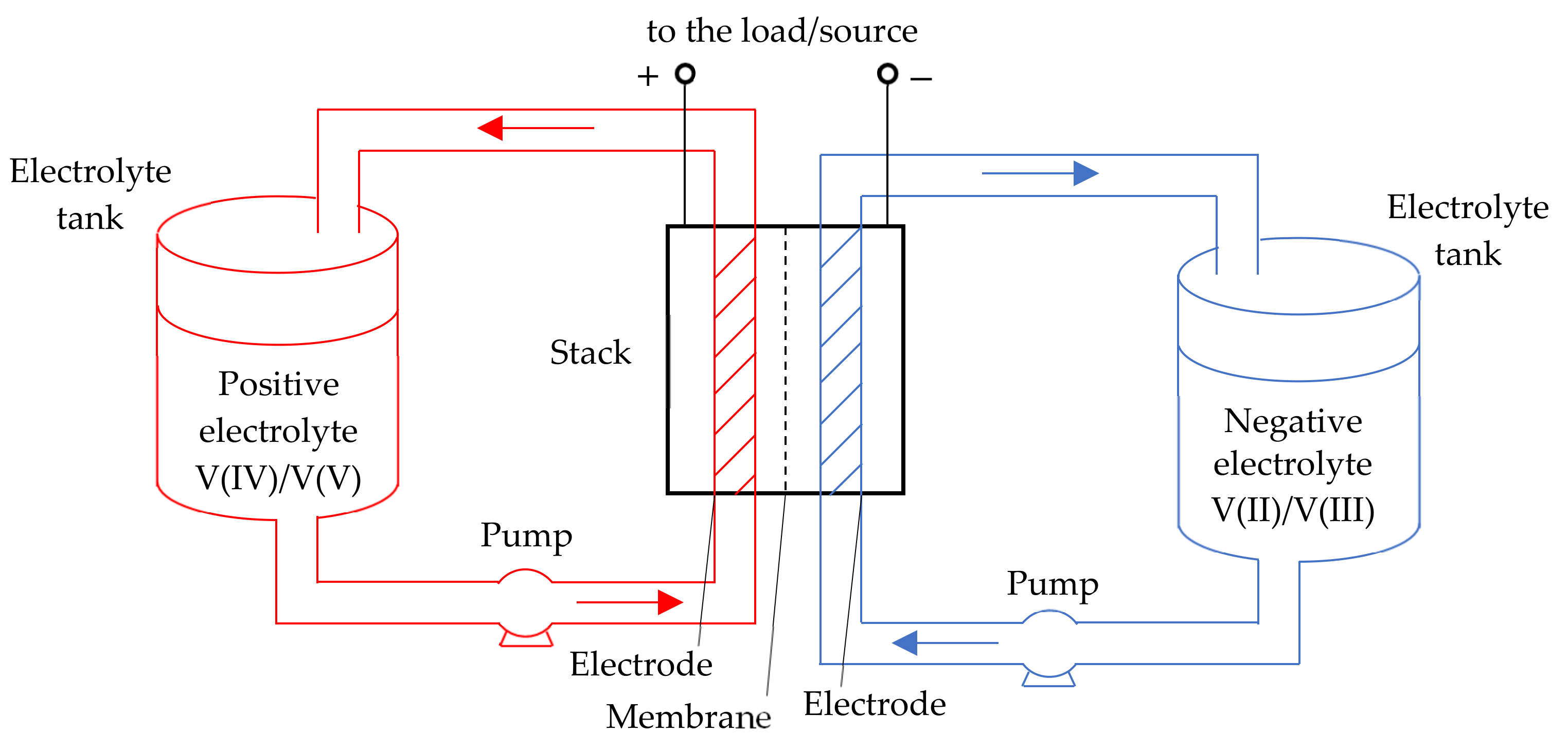
Vanadium redox flow batteries (VRBs) are electrochemical cells that use vanadium ions in various oxidation states as charge carriers. The stack (flow cell) is the main element of VRB. It consists of two porous graphite electrodes separated by an ion exchange membrane. In addition to the stack, the battery includes a hydrodynamic system, which consists of two tanks with positive and negative electrolytes, which are pumped through the electrodes by pumps with an adjustable capacity (Figure 1).
Flow batteries have a long service life (2–4 times longer than lithium-ion and 10 times higher than lead-acid), high flexibility and fast response time. Moreover, the flow batteries advantages include high efficiency (>75%), a wide operating temperature range (from −30 to +60 °C), environmental friendliness, fire and explosion safety. Therefore, flow batteries are the most efficient for accumulating large amounts of energy (from 1 MWh) indoors, where for certain reasons it is not possible to install a diesel generator or other fuel source.
Vanadium redox flow batteries are the most efficient and promising type of flow batteries for commercial use [6]. Currently, three generations of VRB have been developed, differing in the composition of electrolytes, as well as with combinations based on Fe and V ions, such as the vanadium oxygen fuel cell (VOFC) and vanadium hydrogen fuel cell (VHFC) [7]. The use of vanadium ions in both electrolyte tanks eliminates the cross-contamination problem faced by other technologies. In addition to VRB, the best-known flow batteries are iron/chromium redox (Fe/Cr), polysulfide bromine (PSB), zinc-bromine (Zn/Br) and zinc-chlorine (Zn/Cl) [8].
The capacity of the system is determined by the volume of the electrolyte, and the output power is determined by the area of the electrodes. Thus, power and capacity can be increased independently of each other for specific consumer tasks. Table 2 shows the main parameters of the commercially available flow batteries.
The disadvantages of flow batteries include their low volumetric energy density, complex design of the hydrodynamic system, as well as the presence of pumps for electrolyte (consume about 3% of the VRB energy). Unlike traditional electrochemical storage systems (lead-acid, lithium, gel batteries), they are less subject to self-discharge. Despite this, periodic recharging of the batteries and remediation and remixing of electrolytes is required to maintain the nominal capacity [9]. Self-discharge and side reactions in the electrolytes always take place [10,11], so the capacity of flow batteries decreases continuously during the charge/discharges cycling, due to the vanadium species crossover through the ion exchange membrane [12], which is confirmed by open circuit voltage tests [13].
High-power EES systems require a large volume of electrolytes, which makes it possible to use such batteries only as stationary ones, and limits their scope [3]. Thus, flow batteries are a versatile and efficient way to store energy, both in large, centralized power supply systems and in isolated microgrids with their own generation sources, which can be used to level the load curve and increase the efficiency of power transmission [6,8].
According to the US Department of Energy, more than 100 facilities with a total capacity of more than 300 MW were installed in the world by 2021 [14]. If there are no restrictions on the dimensions of the system, large-scale EES systems can be created on the basis of flow batteries (a project with a capacity of 800 MWh was implemented in China) [15]. Data on the largest implemented projects of flow batteries are provided in [7].
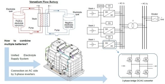
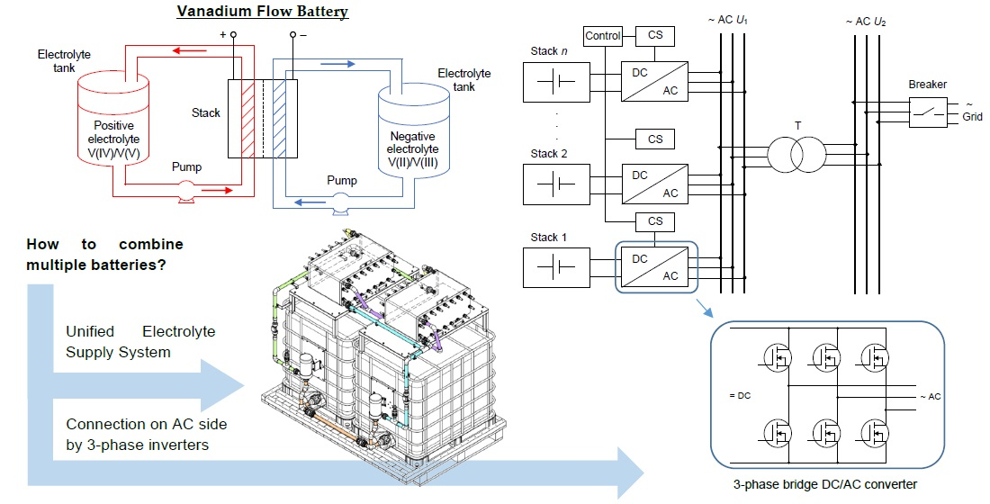
Flow batteries generate a direct current (DC) voltage, while most electrical consumers require an alternating current (AC) voltage. DC/AC converters (or inverters) are used to solve these tasks.
It is necessary to combine several stacks into a single system to create high power EES systems. To do this, stacks can be connected in series (which is performed when assembling flow cells into a single stack) or/and in parallel. A series connection permits an increase in the nominal voltage of the system, and a parallel connection increases the total current of the system, and the voltage remains equal to the voltage of one stack.
The direct parallel connection of stacks is allowed only if their voltages are equal, and even in this case it has many limitations. No two batteries are the same; there are always slight differences in the stack state of charge (SOC), capacity, resistance and temperature characteristics, even if they are the same type, from the same manufacturer and even from the same production batch. Equalizing currents can occur even with slight differences in stack characteristics. In this case, it is not possible to efficiently use each stack, and the overall efficiency of the system will be significantly reduced. Therefore, converters (usually DC/DC) must be used to combine several stacks.
Topologies of hybrid energy storage devices (HESDs), which help to combine different types of EES devices into a single system, are presented in [16]. EES are connected in parallel and DC/DC converters are installed at their output. Having converters for each EES device will permit each battery to function optimally. The correct converter topology must be selected to achieve the optimum operating conditions for flow battery stacks. H. Tao et al. (2008) proposed a multiport structure and three-port topologies converters with the ability to connect several batteries to one converter at once [17]. Transformers for isolation or for efficient voltage boosting are used in the topology of converters. Examples of the use of these devices for flow batteries are not available.
C.-C Wu et al. (2020) proposed a method for combining two fuel cells with different I-V characteristics for parallel operation [18]. The use of transistor DC/DC converters with an inner power feedback loop was proposed. The disadvantage of this method is the large power losses in the converters, which do not allow for the use of this method to create high power systems.
B. Müller (2010) proposed a scheme for combining eight flow stack modules with a power of 250 kW (980 V, 252 A), which uses a single hydrodynamic system with four groups of pumps (one group of pumps for two stack modules) [19]. The flow batteries are combined into two groups of four modules connected in parallel, which are connected in a series and connected to one 2 MW (2 kV, 1 kA) DC/AC inverter. Data on the effectiveness of the proposed solutions are not available.
Thus, combining stacks of flow batteries on the DC side using DC/DC converters is a standard solution [20]; however, it is also possible to combine them on the AC side after the DC/AC inverter. This solution makes it possible to exclude an extra conversion stage from the circuit.
The purpose of this article was to develop a system to ensure the efficient parallel operation of a group of VRB stacks, due to a single hydrodynamic EES system and an interface circuit based on DC/AC converters.
2. Materials and Methods
A stack of a GEC-VFB-5kW vanadium flow batteries (China) was used in the experiments. The stack consists of 37 single cells connected in series with a total active electrode area 8 m2 and rated current density of 18.75 A/m2. It provides a nominal stack voltage of 48 V at a current of 110 A.
A 1.85 M solution of vanadium in a mixture of hydrochloric and sulfuric acids was used as an electrolyte. The average valence of vanadium ions was +3.5. The sulfuric acid concentration was 25% and that of hydrochloric acid was 14%. The solution was prepared by mixing the reagents in a reactor with an overhead stirrer. Vanadium pentoxide with a purity of 99.95% was used as a vanadium precursor. The reduction was carried out at room temperature with 99.97% pure oxalic acid. Phosphoric acid at a concentration of 0.4% was added to the electrolyte as a stabilizer [21,22].
After the reduction of vanadium pentoxide to vanadyl sulfate (vanadium valence +4), the electrolyte was charged until complete oxidation of vanadium in the positive circuit to valence 5+ and the reduction of vanadium in the negative circuit to valence 3+. Afterwards, the electrolyte from the positive circuit was repeatedly reduced to valence 4+ with oxalic acid and mixed with the electrolyte from the negative circuit with valence 3+ in proportions of 1:1. The desired electrolyte was then ready.
2.1. Flow Stack Test Bench
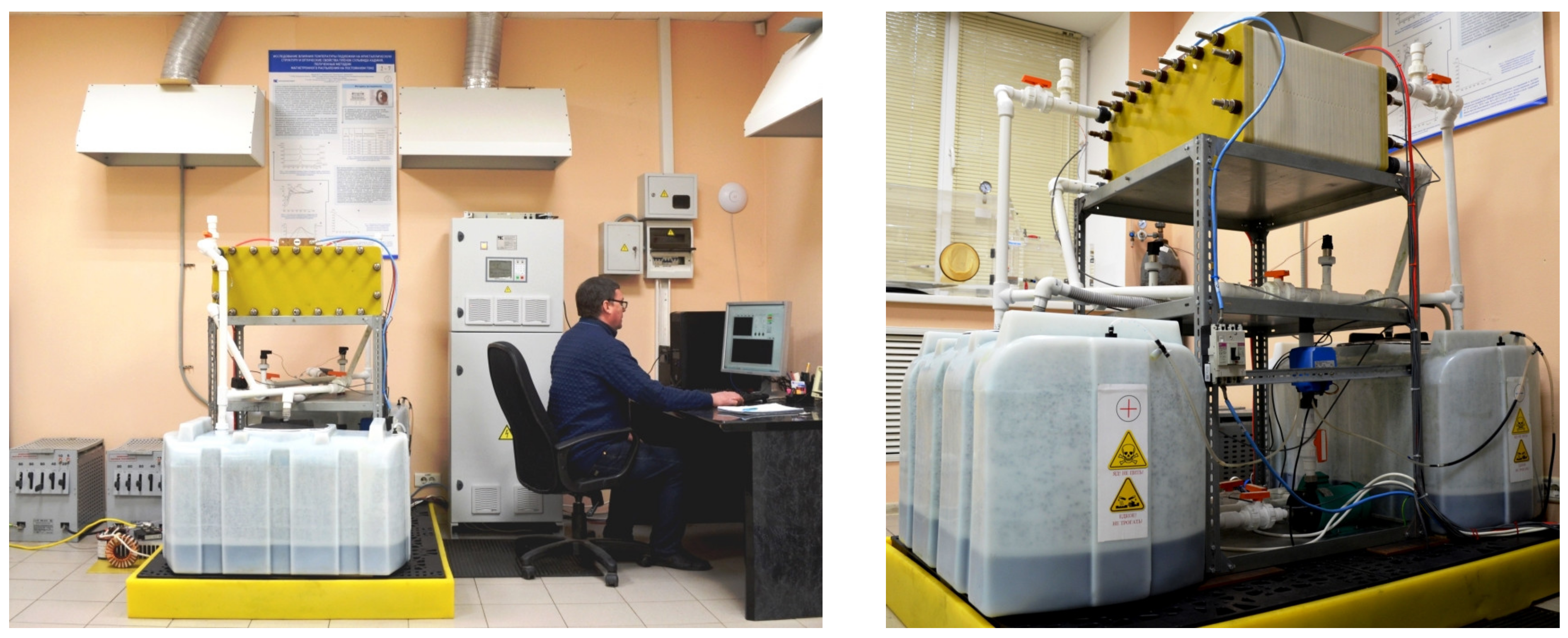
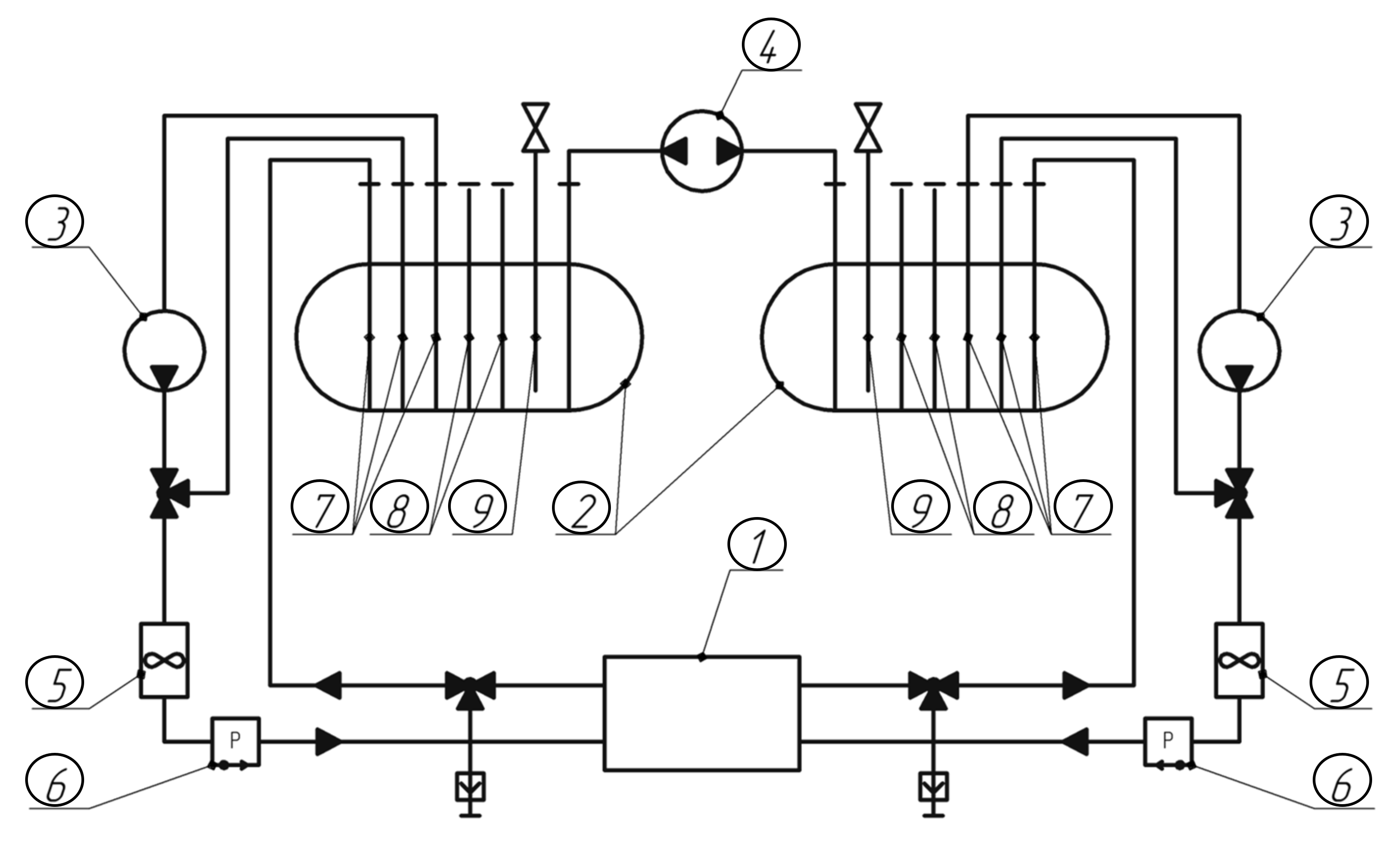
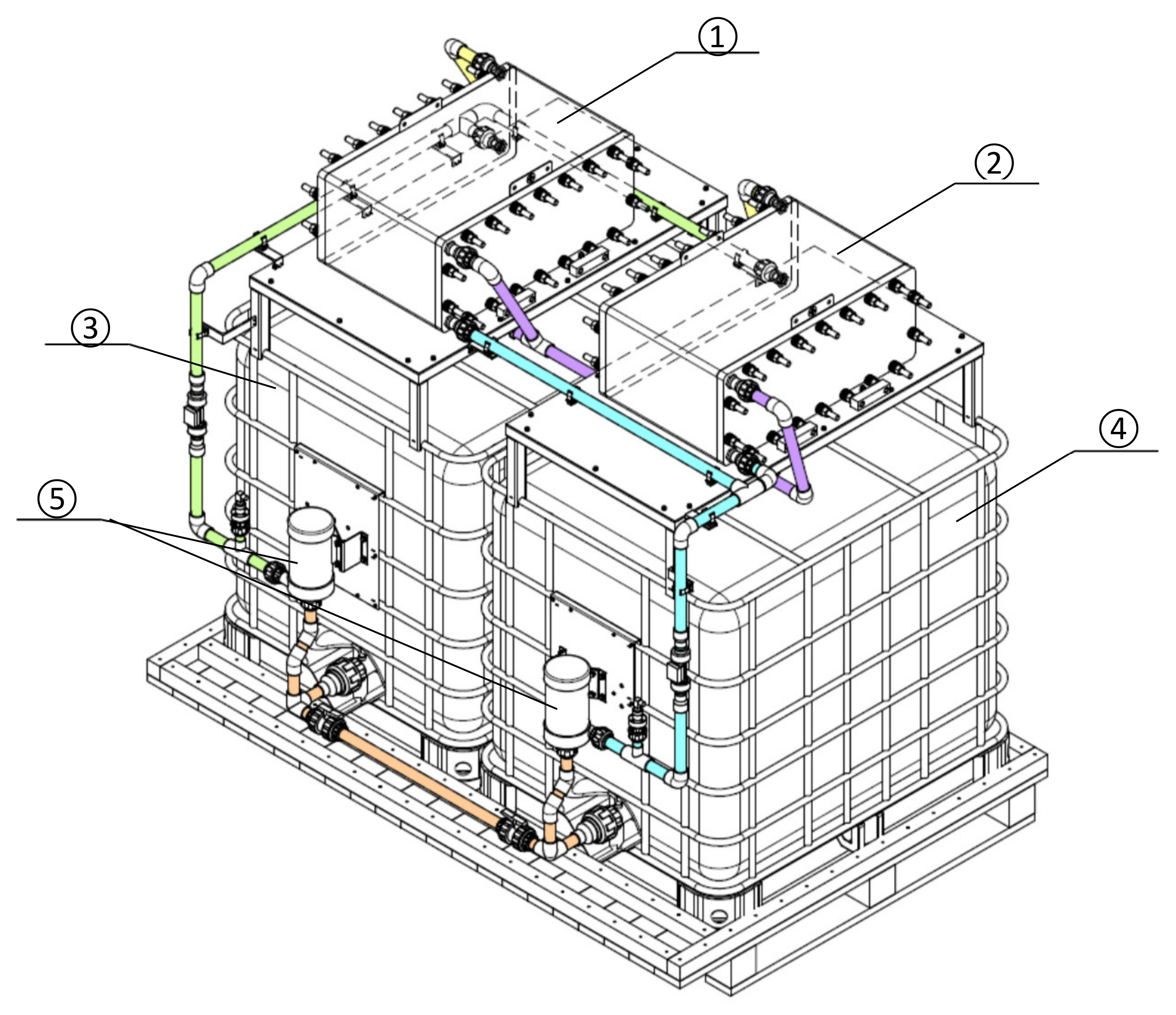
Two test benches (6 kWh and 30 kWh) were developed to test the operating modes of the VRB stack [23]. These benches differed in the volume of electrolyte tanks used, with 2 × 200 L for a 6 kWh bench and 2 × 1000 L for a 30 kWh bench. A photo of the 6 kWh bench is shown in Figure 2, and its hydrodynamic system is shown in Figure 3. The hydraulic system of benches consisted of 2 tanks with electrolyte, 2 frequency-driven pumps for pumping electrolyte, a balancing pump and flow, pressure and temperature sensors in each circuit.
A balancing pump was installed to equalize the levels of positive and negative electrolytes in the tanks, due to the fact that part of the electrolyte from one circuit passes into another through the proton membrane during VRB operation.
The tests were carried out on a 30 kWh bench. The volume of the tanks of positive and negative electrolytes was 1 m3 or 1.3 t. The specific energy stored in electrolytes was 11.54 kWh/t. The stack was tested at an electrolyte pumping rate of 1.5–2 m3/h. The pumping speed was maintained by pumps with an accuracy of 0.1 m3/h and controlled by flow sensors. Charge voltage 54–58 V, charge current 100–150 A. The achieved level of SOC was 20 kWh or 66% of the rated capacity. Cut-off voltage 28 V.
The main technical characteristics of the test bench are outlined in Table 3.
2.2. Test Bench for Two Flow Stacks
3. Results
3.1. Single Flow Stack Tests
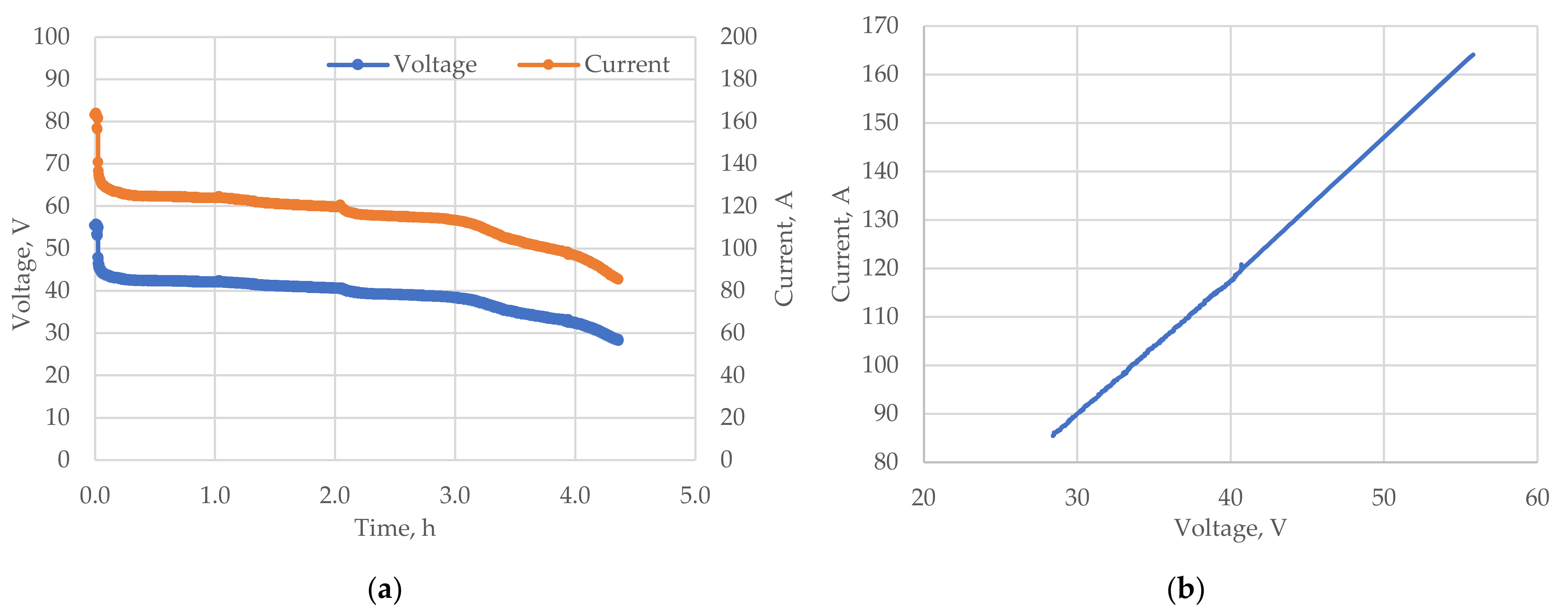
Figure 5 shows the discharge characteristics of the flow stack as well as its I-V characteristics obtained on a test bench. The load current was changed during the discharge phase to build the current–voltage characteristic of the stack. This characteristic is important for tuning the power converters and algorithms of the RFB control system.
From Figure 5b it can be seen that the I-V characteristic of the GEC-VFB-5kW stack is linear in its operating range. The duration of the discharge was 4.5 h.
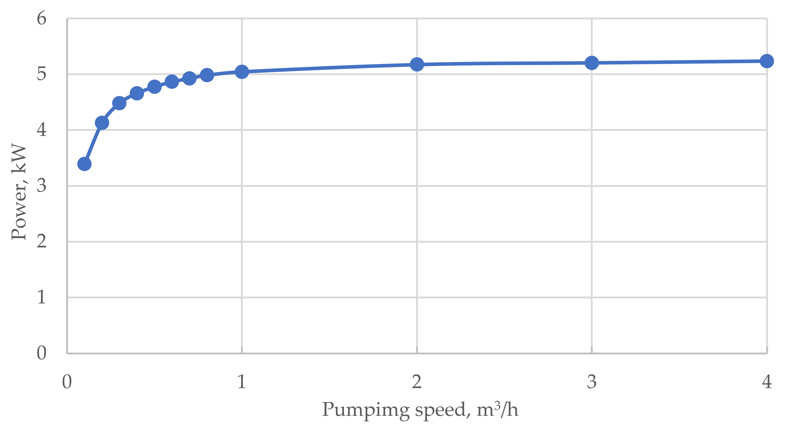
Experiments were also carried out to evaluate the effect of the electrolyte pumping rate on the stack characteristics. Figure 6 shows the stack power as a function of the electrolyte flow rate through the stack.
The electrolyte pumping speed has a significant effect on the stack power at low speeds (up to 1 m3/h). The stack power changes insignificantly from the electrolyte flow rate after reaching a pumping rate of 1 m3/h. Thus, the rate of electrolyte pumping can significantly affect the output characteristics.
3.2. Two Flow Stack Tests
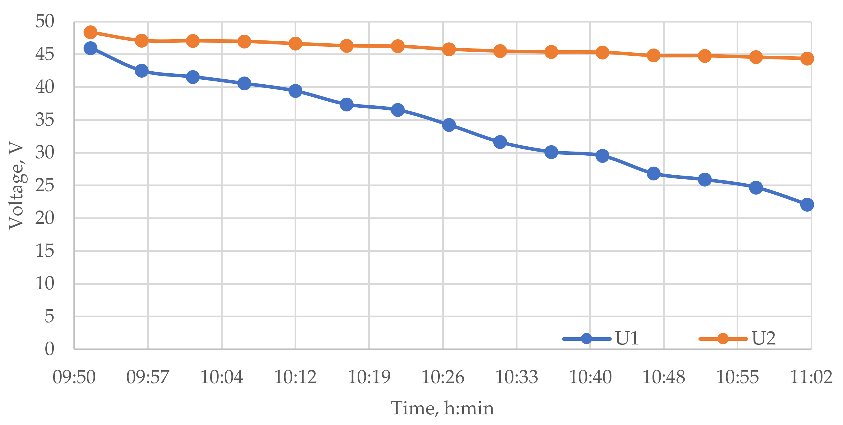
Figure 7 shows the discharge characteristics of the stacks when they are connected in series, obtained for the initial conditions detailed in Table 4.
Despite the same nominal characteristics of the stacks and the common hydrodynamic electrolyte supply system, the same discharge conditions, and the level of initial SOC, the rate of voltage decrease of the stacks differed significantly. There is a significant difference in their voltage, which increases as the discharge progresses, reaching 22.27 V or 41.7% of the initial charge. The reasons for this difference may be as follows:
- Stack internal resistance. The resistances may differ due to the imperfection of the design and electrochemical parameters of the stacks (thickness and dimensions, density and structure of the electrodes, etc.). During the stack operation, a change in the internal resistance and a decrease in the efficiency of their work may be observed due to the influence of the membrane and/or electrodes [13,24]. The degree of influence depends on the number of hours of operation, charge–discharge cycles and their operating conditions.
- Electrolyte pumping speed. In the presence of a single hydrodynamic system for both stacks, it is difficult to maintain the same rate of electrolyte pumping, caused by the impossibility of fine manual adjustment.
Therefore, from Figure 7 we can conclude that the parallel operation of stacks without additional converters is unacceptable. The operation of this system is inefficient, and will lead to the overload of stack #2, which means that special methods must be used to combine several stacks into a single system.
4. Discussion
4.1. Unified Hydrodynamic Electrolyte Supply System
An independent hydrodynamic system with its own electrolyte tank for each stack can be used to maintain the same rate of electrolyte pumping through parallel connected stacks. The adjustment of the electrolyte supply rate will be maintained using pumps and controlled by flow sensors in this case. However, this method leads to additional costs, both in terms of materials and equipment, and for the allotted area for the placement of tanks.
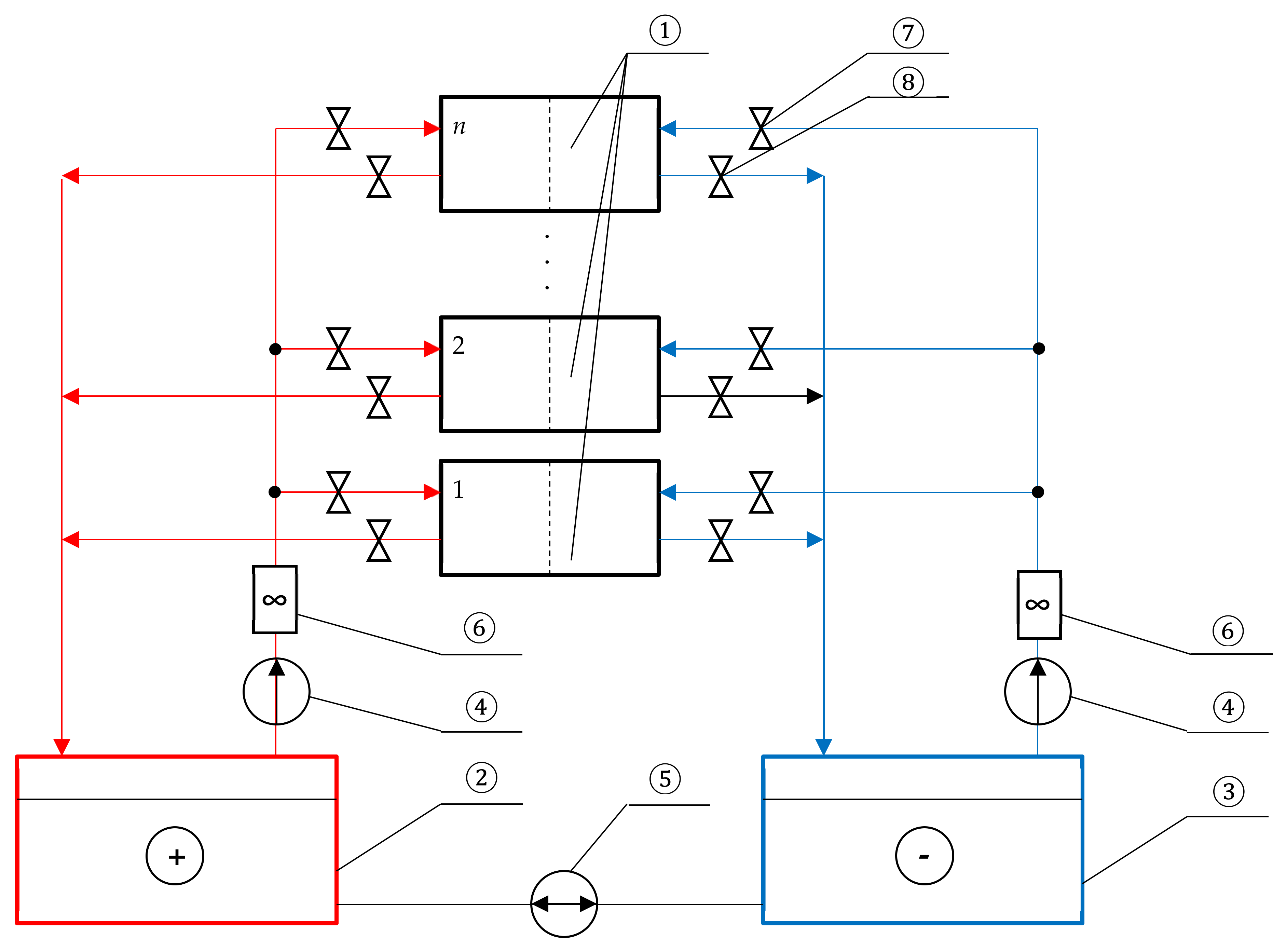
Figure 8 shows a single hydrodynamic scheme that allows one to connect an unlimited number of flow stacks to one set of electrolyte tanks.
Setting the same rate of electrolyte pumping through all stacks is carried out in the following order:
- All stacks except one are disconnected from the electrolyte supply system using shut-off valves 7.
- The pumping speed is adjusted using inlet valve 7 and by controlling the flow rate using sensor 6. When the required speed is reached, output valve 8 is closed.
- Adjustment is made for the next stack. Step 2 is repeated as many times as needed.
It should also be noted that the same flow rate of negative and positive electrolytes should be maintained using the main electrolyte pumps and electrolyte flow sensors.
4.2. Electrical Circuit for VRB Parallel Operation
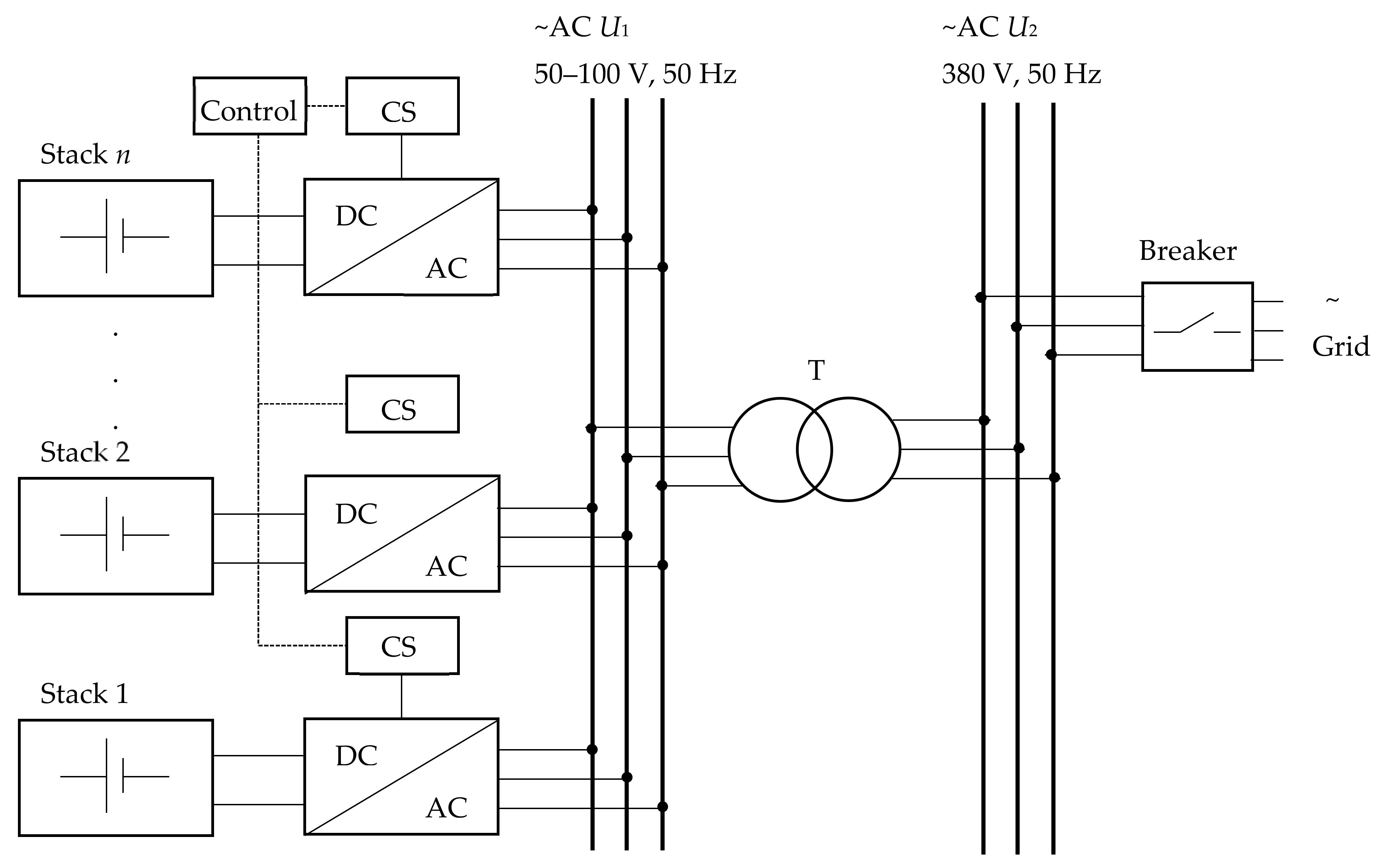
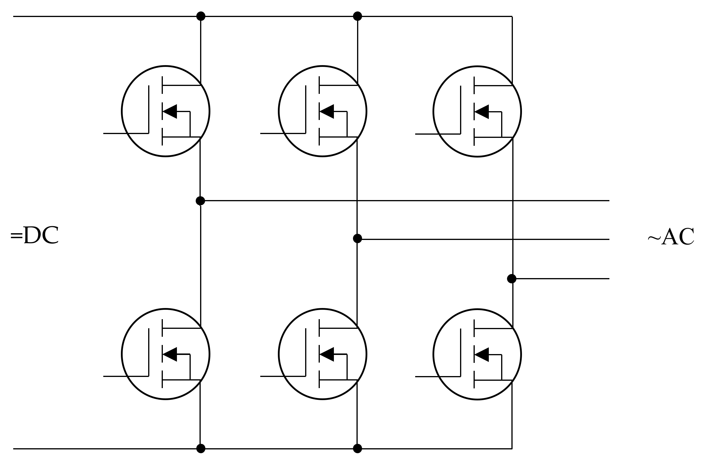
Figure 9 shows a proposed circuit that allows one to combine flow stacks for parallel operation on the AC side. A bi-directional three-phase bridged DC/AC converter is used to convert the stacks’ DC voltage to AC. Its schematic diagram is shown in Figure 10.
The advantage of using DC/AC converters and combining stacks on the AC side is that it is possible to exclude an extra conversion stage from the circuit and increase overall system efficiency compared to a standard solution when DC/DC converters are installed first to combine several stacks, and then the common DC/AC inverter when used to supply the load with an AC current.
A three-phase transformer T can be installed after DC/AC converters for further voltage conversion to the level required by the consumer (grid). It also provides galvanic isolation between the batteries and the AC grid. The electrical grid is connected to the AC voltage bus which is connected to the secondary winding of the transformer.
The system and DC/AC converters are managed by a control system consisting of the following two modules: a single control signal setting system (Control) and own converter control units (CS). A single control system is needed to synchronize the output voltage of the converters and control the power flow of the stacks to the grid (from the grid in charge mode). Own converter control units are used to generate PWM signals to form the output voltages of the converters and equalize the voltage amplitudes of the stacks.
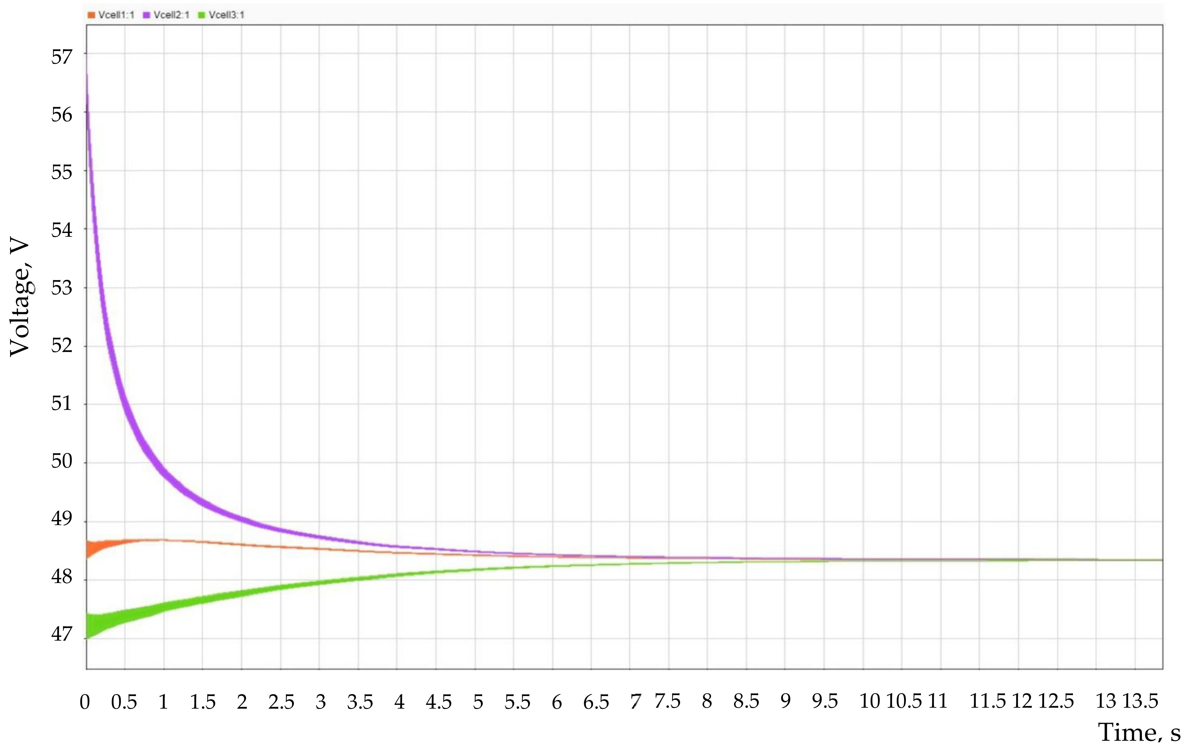
A Matlab Simulink model was developed to test the performance of the proposed circuit. Figure 11 shows a plot of the voltage change when three VRB stacks are connected in parallel using the proposed circuit.
The initial voltages of the stacks were different, and the maximum difference reached 8.5 V or ~18% of the nominal value of the stack voltage. The system required 10 s to equalize the voltage of all stacks.
5. Conclusions
Flow stacks must be combined into a single system to create high power storage systems based on flow batteries. Direct connection on the DC bus without the use of intermediate converters is not allowed due to the difference in the output voltages of the stacks.
Bidirectional DC/AC converters must be used to combine stacks and equalize their output voltage. The required voltage level at the output of the inverter is provided by a transformer. In addition, the use of a single hydrodynamic electrolyte supply system is proposed, which, without additional capital costs, ensures the same rate of electrolyte is pumped through each stack.
Author Contributions
Conceptualization, A.L., A.K. and I.L.; methodology, A.L. and A.K.; software, I.K.; validation, I.K.; formal analysis, A.K.; investigation, A.L.; resources, I.K.; data curation, A.L.; writing—original draft preparation, A.L., A.K. and I.L.; writing—review and editing, A.L. and A.K.; visualization, I.L.; supervision, A.K.; project administration, A.L. and A.K.; funding acquisition, A.K. All authors have read and agreed to the published version of the manuscript.
Funding
The reported study was funded by Council of the grants of President of the Russian Federation for the state support of Leading Scientific Schools of the Russian Federation (Grant No. NSH-70.2022.1.5).
Institutional Review Board Statement
Not applicable.
Conflicts of Interest
The authors declare no conflict of interest.
References
- Alotto, P.; Guarnieri, M.; Moro, F. Redox flow batteries for the storage of renewable energy: A review. Renew. Sustain. Energy Rev. 2014, 29, 325–335. [Google Scholar] [CrossRef]
- Duraman, N.P.H.; Lim, K.L.; Chan, S.L.I. Batteries for remote area power (RAP) supply systems. In Advances in Batteries for Medium and Large-Scale Energy Storage, Types and Applications; Series in Energy; Woodhead Publishing: Sawston, UK, 2015; pp. 563–586. [Google Scholar] [CrossRef]
- Nordling, A.; Englund, R.; Hembjer, A.; Mannberg, A. Energy Storage: Electricity Storage Technologies; IVA’s Electricity Crossroads Project; Royal Swedish Academy of Engineering Sciences: Stockholm, Sweden, 2016. [Google Scholar]
- Mostert, C.; Ostrander, B.; Bringezu, S.; Kneiske, T.M. Comparing electrical energy storage technologies regarding their material and carbon footprint. Energies 2018, 11, 3386. [Google Scholar] [CrossRef]
- Weber, A.Z.; Mench, M.M.; Meyers, J.P.; Ross, P.N.; Gostick, J.T.; Liu, Q. Redox flow batteries: A review. J. Appl. Electrochem. 2011, 41, 1137. [Google Scholar] [CrossRef]
- Skyllas-Kazacos, M.; Chakrabarti, M.H.; Hajimolana, S.A.; Mjalli, F.S.; Saleem, M. Progress in flow battery research and development. J. Electrochem. Soc. 2011, 158, R55–R79. [Google Scholar] [CrossRef]
- Skyllas-Kazacos, M.; McCann, J.F. Vanadium redox flow batteries (VRBs) for medium- and large-scale energy storage. In Advances in Batteries for Medium- and Large-Scale Energy Storage. Types and Applications; Series in Energy; Woodhead Publishing: Cambridge, UK, 2015; pp. 329–386. [Google Scholar] [CrossRef]
- Skyllas-Kazacos, M.; Menictas, C.; Lim, T. Redox flow batteries for medium- to large-scale energy storage. In Electricity Transmission, Distribution and Storage Systems; Series in Energy; Woodhead Publishing: Cambridge, UK, 2013; pp. 398–441. [Google Scholar] [CrossRef]
- Chen, N.; Zhang, H.; Luo, X.-D.; Sun, C.-Y. SiO2-decorated graphite felt electrode by silicic acid etching for iron-chromium redox flow battery. Electrochim. Acta 2022, 336, 135646. [Google Scholar] [CrossRef]
- Luo, Q.; Li, L.; Wang, W.; Nie, Z.; Wei, X.; Li, B.; Chen, B.; Yang, Z.; Sprenkle, V. Capacity decay and remediation of Nafion-based all-vanadium redox flow batteries. ChemSusChem 2013, 6, 268–274. [Google Scholar] [CrossRef] [PubMed]
- Di Noto, V.; Vezzù, K.; Crivellaro, G.; Pagot, G.; Sun, C.; Meda, L.; Rutkowska, I.A.; Kulesza, P.J.; Zawodzinski, T.A. A general electrochemical formalism for vanadium redox flow batteries. Electrochim. Acta 2022, 408, 139937. [Google Scholar] [CrossRef]
- Sun, C.; Negro, E.; Nale, A.; Pagot, G.; Vezzù, K.; Zawodzinski, T.A.; Meda, L.; Gambaro, C.; Di Noto, V. An efficient barrier toward vanadium crossover in redox flow batteries: The bilayer [Nafion/(WO3)x] hybrid inorganic-organic membrane. Electrochim. Acta 2021, 378, 138133. [Google Scholar] [CrossRef]
- Zhang, D.; Xu, Z.; Zhang, X.; Zhao, L.; Zhao, Y.; Wang, S.; Liu, W.; Che, X.; Yang, J.; Liu, J.; et al. Oriented proton-conductive nanochannels boosting a highly conductive proton-exchange membrane for a vanadium redox flow battery. ACS Appl. Mater. Interfaces 2021, 13, 4051–4061. [Google Scholar] [CrossRef] [PubMed]
- U.S. Department of Energy. Available online: https://www.energy.gov/ (accessed on 9 June 2022).
- Sánchez-Díez, E.; Ventosa, E.; Guarnieri, M.; Trovò, A.; Flox, C.; Marcilla, R.; Soavi, F.; Mazúr, P.; Aranzabe, E.; Ferret, R. Redox flow batteries: Status and perspective towards sustainable stationary energy storage. J. Power Sources 2021, 481, 228804. [Google Scholar] [CrossRef]
- Vazquez, S.; Lukic, S.M.; Galvan, E.; Franquelo, L.G.; Carrasco, J.M. Energy storage systems for transport and grid applications. IEEE Trans. Ind. Electron. 2010, 57, 3881–3895. [Google Scholar] [CrossRef]
- Tao, H.; Duarte, J.L.; Hendrix, M.A.M. Multiport converters for hybrid power sources. In Proceedings of the 2008 IEEE Power Electronics Specialists Conference, Rhodes, Greece, 15–19 June 2008. [Google Scholar] [CrossRef]
- Wu, C.-C.; Chen, T.-L. Design and experiment of a power sharing control circuit for parallel fuel cell modules. Energies 2020, 13, 2838. [Google Scholar] [CrossRef]
- Müller, B. Electricity on tap. Fraunhofer Magazine, 1 October 2010; 14–15. [Google Scholar]
- Chirkin, V.G.; Khripach, N.A.; Shustrov, F.A.; Tatarnikov, A.P. Review on DC-DC power converter topologies and control technics for hybrid storage systems. Int. J. Mech. Eng. Technol. 2018, 9, 985–992. [Google Scholar]
- Zhang, Z.H.; Wei, L.; Wu, M.C.; Bai, B.F.; Zhao, T.S. Chloride ions as an electrolyte additive for high performance vanadium redox flow batteries. Appl. Energy 2021, 289, 116690. [Google Scholar] [CrossRef]
- Carvalho, W.M.; Cassayre, L.; Quaranta, D.; Chauvet, F.; El-Hage, R.; Tzedakis, T.; Biscans, B. Stability of highly supersaturated vanadium electrolyte solution and characterization of precipitated phases for vanadium redox flow battery. J. Energy Chem. 2021, 61, 436–445. [Google Scholar] [CrossRef]
- Kuzmin, I.; Loskutov, A.; Osetrov, E.; Kurkin, A. Source for autonomous power supply system based on flow battery. Energies 2022, 15, 3027. [Google Scholar] [CrossRef]
- Nibel, O.; Taylor, S.M.; Patru, A.; Fabbri, E.; Gubler, L.; Schmidt, T.J. Performance of different carbon electrode materials: Insights into stability and degradation under real vanadium redox flow battery operating conditions. J. Electrochem. Soc. 2017, 164, A1608–A1615. [Google Scholar] [CrossRef]
Figure 1.
Circuit diagram of the VRB cell.

Figure 2.
6 kWh VRB test bench.

Figure 3.
Hydrodynamic scheme of the VRB test bench: 1—VRB stack; 2—tanks with electrolyte; 3—main pumps for pumping electrolyte; 4—balancing pump; 5—electrolyte flow sensors; 6—pressure sensors; 7—outlet pipes; 8—branch pipes with an outlet in the form of a fitting; 9—branch pipes with pressure relief valves.

Figure 4.
Scheme of a test bench with two flow stacks: 1, 2—VRB stack; 3—positive electrolyte tank; 4—negative electrolyte tank; 5—pumps.
Figure 4.
Scheme of a test bench with two flow stacks: 1, 2—VRB stack; 3—positive electrolyte tank; 4—negative electrolyte tank; 5—pumps.

Figure 5.
Characteristics of the GEC-VFB-5kW stack: (a) discharge; (b) I–V characteristic.

Figure 6.
Dependence of stack power on electrolyte flow rate.

Figure 7.
Discharged characteristics for stacks #1 and #2.

Figure 8.
Hydrodynamic scheme for connecting multiple flow stacks: 1—VRB stack (n pieces); 2 and 3—electrolyte tanks; 4—main electrolyte pumps; 5—balancing pump; 6—electrolyte flow sensors; 7—input valves; 8—outlet valves.
Figure 8.
Hydrodynamic scheme for connecting multiple flow stacks: 1—VRB stack (n pieces); 2 and 3—electrolyte tanks; 4—main electrolyte pumps; 5—balancing pump; 6—electrolyte flow sensors; 7—input valves; 8—outlet valves.

Figure 9.
Functional diagram of circuit for VRB parallel operation.

Figure 10.
Three-phase bridge DC/AC converter.

Figure 11.
Changing the stack voltage when they are connected in parallel using a group of DC/AC converters.
Figure 11.
Changing the stack voltage when they are connected in parallel using a group of DC/AC converters.


Table 1.
Characteristics of existing EES technologies.
| Technology | Rated Power, MW | Usage Time | Self-Discharge, % per Day | Gravimetric Energy Density, Wh/kg | Volumetric Energy Density, Wh/L | Power Density, W/kg | Efficiency, % | Lifetime, Cycles (No Less Than) |
|---|---|---|---|---|---|---|---|---|
| Electrochemical | ||||||||
| Lead acid | 0.001–50 | s–3 h | 0.1–0.8 | 30–50 | 50–80 | 75–300 | 70–90 | 500–1200 |
| Lithium-ion | 0.1–100 | min–h | 0.1–0.3 | 75–270 | 200–600 | 100–10,000 | 85–98 | 1000–25,000 |
| Nickel cadmium | 0.1–50 | min–h | 0.2–1 | 50–75 | 60–150 | 150–230 | 60–90 | 1000–2500 |
| Nickel metal hydride | 0.01–1 | min–h | 0.5–1 | 40–110 | 220–428 | 250–2000 | 50–80 | 200–1500 |
| Sodium sulfur battery (NaS) | 0.05–100 | s–h | 0.05 | 150–300 | 150–300 | 150–230 | 70–90 | 2000–5000 |
| Vanadium redox flow battery | 0.1–200 | s–10 h | 0.06 | 10–75 | 20–70 | 80–150 | 60–90 | 12,000–14,000 |
| Zinc bromine flow battery | up to 1 | s–10 h | 0.06 | 60–85 | 30–65 | 50–150 | 75–80 | 2000 |
| Electrical | ||||||||
| Supercapacitor (SC) | 0.01–1 | ms–s | 2–4 | 1.5–110 | 40–100 | 40,000–120,000 | 80–98 | 10,000–100,000 |
| Superconducting magnetic energy storage (SMES) | 0.001–10 | s | 0 | 1–60 | up to 10 | (10,000–100,000) × 103 | 80–95 | 100,000 |
| Mechanical | ||||||||
| Hydro-pumped storage (HPS) | 20–5000 | 1–24 h | 0–0.5 | 0.3 | 0.2–2 | 0.1–0.2 | 70–85 | 30–60 years |
| Compressed air energy storage (CAES) | 10–1000 | 1–24 h | 0–10 | 10–30 | 0.5–0.8 (at 60 bar) | 0.2–0.6 | 40–75 | 20–40 years |
| Flywheel energy storage (FES) | 0.002–400 | s–min | 1.3–100 | 5–200 | 1000–5000 | 70–95 | 20,000–100,000 | |
| Chemical | ||||||||
| Hydrogen (H2) | 0.01–1000 | s–months | 0–4 | - | 600 | 0.2–20 | 25–82 | 5–10 years |
| Synthetic natural gas (SNG) | 50–1000 | s–months | 0–1 | - | 1800 | 0.2–2 | 25–56 | 30 years |
Table 2.
Parameters of commercially available flow batteries.
| Model | Country | Company | Power, MW | Capacity, MWh | Lifetime, Cycles (No Less Than) |
|---|---|---|---|---|---|
| 2015 Uni.System™ (AC) | USA | UniEnergy Technologies, LLC | 0.6 | 2.2 | 12,000 |
| VNX1000-10 | USA | Vionx Energy Corporation | 1 | 10 | 20 years |
| GEC-VFB-10kW30kWh | China | Golden Energy Century Ltd. | 0.01 | 0.03 | 20,000 |
| Vpower1 | China | Rongke Power Co., Ltd. | 0.5 | 2 | 10,000 |
Table 3.
30 kWh test bench characteristics.
| Parameter | Value, Unit |
|---|---|
| Main pumps maximum performance | 4 m3/h |
| Balancing pump performance | 20 L/h |
| Range of electrolyte flow rates | 1 … 2.5 m3/h |
| Electrolyte pressure measurement range at stack inlet | 0.1 … 100 kPa ± 3% |
| Operating pressure range in tanks | −7.5 … +7.5 kPa |
| Volume of tanks with electrolyte | 1 m3 |
Table 4.
Initial data for tests.
| Parameter | Value, Unit |
|---|---|
| Discharge current | 100 A |
| Pressure (−) | 36 kPa |
| Pressure (+) | 43 kPa |
| Electrolyte is charged up to | 40 A |
| Charge of stack #1, U1 | 53.42 V |
| Charge of stack #2, U2 | 53.18 V |
Publisher’s Note: MDPI stays neutral with regard to jurisdictional claims in published maps and institutional affiliations. |
© 2022 by the authors. Licensee MDPI, Basel, Switzerland. This article is an open access article distributed under the terms and conditions of the Creative Commons Attribution (CC BY) license (https://creativecommons.org/licenses/by/4.0/).
Share and Cite
MDPI and ACS Style
Loskutov, A.; Kurkin, A.; Kuzmin, I.; Lipuzhin, I. Ways to Ensure Parallel Operation of Vanadium Flow Batteries to Create High Power Energy Storage Systems. Batteries 2022, 8, 120. https://doi.org/10.3390/batteries8090120
AMA Style
Loskutov A, Kurkin A, Kuzmin I, Lipuzhin I. Ways to Ensure Parallel Operation of Vanadium Flow Batteries to Create High Power Energy Storage Systems. Batteries. 2022; 8(9):120. https://doi.org/10.3390/batteries8090120
Chicago/Turabian StyleLoskutov, Alexey, Andrey Kurkin, Ivan Kuzmin, and Ivan Lipuzhin. 2022. "Ways to Ensure Parallel Operation of Vanadium Flow Batteries to Create High Power Energy Storage Systems" Batteries 8, no. 9: 120. https://doi.org/10.3390/batteries8090120
Note that from the first issue of 2016, this journal uses article numbers instead of page numbers. See further details here.