
Electrochemical Properties of LiFePO4 Cathodes: The Effect of Carbon Additives

1
Kurnakov Institute of General and Inorganic Chemistry, Russian Academy of Sciences, Leninsky prospekt 31, Moscow 119991, Russia
2
Basic Department of Inorganic Chemistry and Materials Science, National Research University Higher School of Economics, ul. Myasnitskaya 20, Moscow 101000, Russia
3
Frumkin Institute of Physical Chemistry and Electrochemistry, Russian Academy of Sciences, Leninsky prospekt 31-4, Moscow 119071, Russia
*
Author to whom correspondence should be addressed.
Batteries 2022, 8(9), 111; https://doi.org/10.3390/batteries8090111
Submission received: 30 July 2022
/
Revised: 25 August 2022
/
Accepted: 2 September 2022
/
Published: 5 September 2022
(This article belongs to the Section Battery Modelling, Simulation, Management and Application)
Abstract
:The influence of different conductive additives (carbon nanofibers (CNFs), carbon nanoplatelets, and pyrolytic carbon from sucrose (Sucr) or polyvinylidene fluoride) on the morphology, electron conductivity, and electrochemical performance of LiFePO4-based cathodes was investigated to develop the most efficient strategy for the fabrication of high-rate cathodes. Pyrolytic carbon effectively prevents the growth of LiFePO4 grains and provides contact between them, CNFs provide fast long-range conductive pathways, while carbon nanoplatelets can be embedded in carbon coatings as high-conductive “points” which enhance the rate capability and decrease the capacity fading of LFP. The LiFePO4/CSucr/CNF showed better performance than the other cathodes due to the synergy of the high-conductive CNF network (the electronic conductivity was 1.3 × 10⁻² S/cm) and the shorter Li+ ion path (the lithium-ion diffusion coefficient was 2.1 × 10⁻¹¹ cm2/s). It is shown that the formation of composites based on LFP and carbon nanomaterials via mortar grinding is a more promising strategy for electrode material manufacturing than ball milling.
1. Introduction
At present, among rechargeable batteries, lithium-ion batteries (LIBs) are the most common due to their several advantages, such as high energy density, safety, long service life, and environmental friendliness [1,2]. LIBs are increasingly used in drones, electric vehicles (EVs), and hybrid electric vehicles (HEVs), and are essential power sources for power tools and modern electronics, including computers and cellphones [3,4,5,6,7]. Two of the most important characteristics of LIBs are their specific energy and power, which are primarily limited by the voltage and capacity of cathodes [1]. At present, the market is dominated by batteries with cathodes made from LiCoO2 or complex metal oxides [8,9], the use of which is associated with a number of problems, including safety issues [10]. The search for new materials with high reliability is therefore of particular importance.
The olivine-type LiFePO4 (LFP) is one of the most promising LIB cathode materials due to its safety, low cost, high thermal stability, low toxicity, relatively high theoretical electrochemical capacity, and operating potential [11,12]. Its main disadvantages are low electronic conductivity and slow lithium-ion diffusion (10–9 S/cm and 10–16 cm2/s, respectively) through the layer of FePO4 (LiFePO4) formed during lithium deintercalation (intercalation) (FePO4 + Li ↔ LiFePO4), which significantly limits the use of LFP in EVs, HEVs, etc. In many modern applications, the most important parameter is high battery power, that is, the possibility of high discharge to maintain high capacity [13,14]. To overcome the aforementioned limitations, a number of approaches are widely used: the synthesis of nanosized materials [15,16,17], heterovalent doping of both cationic and anionic sublattices [18,19,20], and the coating of LiFePO4 particles with conductive materials [21,22,23].
Carbon coating and/or the introduction of carbon materials (primarily nanomaterials) seem to be the most effective ways of improving the electronic conductivity of LFP [13,23]. During coating, the carbon precursor (various carbohydrates, organic acids, and polymers) is carbonized at a high temperature (in order to convert carbon atoms to sp2-hybridization) in the presence of LiFePO4 or its precursor. In the latter case, the carbon layer not only uniformly covers the LFP, forming a core–shell structure with improved conductivity, but also limits the growth of LFP particles. However, in this case, it is not always possible to form a continuous, highly conductive network due to the non-uniformity of the created carbon coating. Moreover, the contacts between the particles of the electrode material are predominantly point-like, resulting in low conductivity and efficiency. The development of an effective method for modifying conductive carbon coatings to increase LFP electronic conductivity is therefore still relevant. For this purpose, different carbon sources (polyaniline, dopamine, and polybenzoxazine) are used to obtain N-doped carbon coatings [24,25,26] or F-doped coatings from polyvinylidene fluoride (PVDF) [27,28,29], which seem to be the most promising. During carbonization, PVDF can act as a carbon and fluorine source, since not all fluorine is lost in its decomposition. Some fluorine remains in the carbon coating, changing its conductivity and interaction with the surface of the electrode material. The introduction of carbon nanomaterials (graphene particles and carbon nanotubes, including doped ones [30,31,32,33,34]) with high electronic conductivities and surface areas can lead to improvements in the contacts between particles in electrode materials, the formation of highly conductive networks, and, thus, to significant improvements in the electrochemical properties of electrode materials. For instance, Sun et al. [32] used a spray-drying method to synthesize multi-walled carbon-nanotube-decorated LiFePO4 with a conductive 3D network. Hence, the initial discharge capacities (158 mAh/g at 0.1 C and 154 mAh/g at 0.5 C) and long-term cycling of the prepared composite were significantly better than those of the LFP/C. Lei et al. [30] also synthesized an LFP composite with carbon nanotubes (CNTs) and graphene (G) as carbon additives, using a solid-state wet ball-milling method. The synergistic effects of graphene nanosheets and CNTs improve the rate capabilities and cycling stabilities of LiFePO4-based cathodes. The LFP/CNT/G electrode shows a reversible capacity of 168.9 mAh/g at 0.2 C and an excellent cycling performance. The initial discharge capacity of the LiFePO4 in situ vapor-grown carbon-fiber composite increased from 109 to 144 mAh/g at 0.5 C compared with the bare cathode [35]. However, some drawbacks of composites prepared with carbon nanomaterials should be noted: the latter are prone to agglomeration and are often unevenly distributed. To ensure a uniform distribution of carbon nanomaterials and a better mixing of the initial components, high-energy ball milling is often used to prepare composite electrode materials. However, such treatment can also lead to the degradation of carbon nanomaterials and interfere with the improvement of electrochemical characteristics. Therefore, it is of interest to compare different ways of introducing carbon nanomaterials. Moreover, based on the above research, there is a problem in comparing the effects of different carbon additives on the electrochemical properties of obtained composites, because different conditions are used for composite fabrication (the preparation method, the final annealing temperature, the contents of carbon materials, etc.) and the effects on the final composites cannot be reliably explained. There are practically no works devoted to the simultaneous study of the effects of several carbon nanomaterials, although this may be advantageous (carbon coatings form reliable contacts with the surfaces of electrode material particles, while extended carbon structures, such as CNTs, form good contacts between them). Therefore, our research focuses on the simultaneous study of various carbon additives using a simple method of in situ synthesis to understand the relationships between composite composition and electrochemical performance.
In this work, LFP-based composites were synthesized using different carbon nanomaterials (carbon nanofibers and carbon nanoplatelets). Due to their high electronic conductivity and excellent mechanical stability, carbon nanofibers can be regarded as ideal one-dimensional conductive additives for electrodes. Carbon nanoplatelets are, in fact, agglomerates of randomly packed graphene particles and layers, which can be destroyed by co-processing in a mortar or planetary mill with carbon nanoplatelets and electrode materials, forming graphene-like inclusions in the carbon coatings. Moreover, two different sources of pyrolitic carbon (sucrose and polyvinylidene fluoride) were used for bare and reference (CSucr) and fluorine-doped (CPVDF) carbon coatings, respectively. To the best of our knowledge, the simultaneous F-doped carbon coating obtained with PVDF and carbon nanomaterial addition was investigated for the first time. To determine the most appropriate way of introducing carbon nanomaterials, the LFP/C composites were fabricated using both mortar grinding and high-energy ball milling.
2. Materials and Methods
The chemical vapor deposition technique was used to synthesize carbon nanofibers (CNFs) and carbon nanoplatelets (CNPs). They were prepared by flowing a gas mixture of CH4–H2 (the CH4/H2 ratio was 1.5) over a fixed catalyst (Co/MgO and MgO for the synthesis of CNFs and CNPs, respectively) at 750–850 °C. HCl solution was used to remove the catalyst. Carbon nanomaterials (CNMs) were washed with deionized water and dried at 90 °C.
Iron(III) nitrate (Sigma-Aldrich, >98%, St. Louis, MO, USA), lithium nitrate (Sigma-Aldrich, >99%), and ammonium dihydrogen phosphate (Sigma-Aldrich, >98%) were used for the LiFePO4 synthesis. Their stoichiometric amounts were dissolved in water under constant stirring and treated at 70 °C to form a homogeneous suspension, which was then heated at 300 °C for 6 h. The LFP-based composites were obtained by mixing the LiFePO4 precursor and CNFs or CNPs in an agate mortar or planetary mill. In the latter case, mechanical treatment was carried out in a Fritch Pulverisette 7 classic line planetary mill for 8 h at 500 rpm, using agate grinding jars and balls; the medium was ethanol. Based on previously obtained data [36], the amount of carbon nanomaterial was 10 wt.%. Then, sucrose (Sucr, 25 wt.%) or an appropriate amount of an 8% solution of polyvinylidene fluoride (PVDF) in N-methylpyrrolidone was added to the resulting precursor and annealed at 600 °C for 10 h in Ar. The subscripts “Sucr” and “PVDF” in the names of the prepared composites indicate the pyrolytic carbon source: sucrose and polyvinylidene fluoride, respectively. In the case of the high-energy ball milling of the LFP precursor with carbon nanomaterials, the subscript “bm” was used, e.g., LFP/CPVDF/CNPbm.
X-ray powder diffraction (XRD) analysis of the prepared composites was performed on a Rigaku D/MAX 2200 diffractometer (Japan) with a diffraction angle range of 10–60° at a rate of 2°/min. The crystallite size (coherent scattering region, CSR) was estimated from the XRD reflex broadening using the Scherrer Equation (1):
where λ represents the X-ray wavelength, Θ is the Bragg angle, and β represents the line broadening at half the maximum intensity. The shape factor K was taken as 0.89. LaB6 was used as a reflex broadening standard. The analysis of the morphology of the prepared composites was carried out with a Tescan Amber scanning electron microscope (Tescan, Brno, Czech Republic) in the modes of secondary and backscattered electrons. An Oxford Instruments X-MAX energy-dispersive X-ray spectroscopy (EDS) detector was used for EDS microprobe analysis. According to the EDS data, the LFP/CPVDF composite contained about 1.5 at.% fluorine. The carbon content was determined with an elemental analyzer EuroVektor EA3000 (EuroVektor, Pavia, Italy). The Brunauer–Emmet–Teller isotherm method was used for the surface area measurements with low-temperature nitrogen adsorption at 196 °C on a Sorbtometer-M analyzer (Katakon, Russia). Before measurement, the samples were degassed at 200 °C for 1 h.
CSR = Kλ/(βcosΘ)
Galvanostatic charge–discharge tests were performed using a 50 mA–10 V ZRU charge–discharge stand (Buster, Russia) in sealed three-electrode cells in the potential range of 2.5–4.1 V (vs Li+/Li) at current densities of 20–3200 mA/g. The cells were assembled in a glovebox in a dry Ar atmosphere, with non-woven polypropylene as the separator and 1 M LiPF6 in ethylene carbonate, diethyl carbonate, and dimethyl carbonate (1/1/1 vol/vol/vol) as the electrolyte. The cathode slurry was fabricated by grinding in a mortar the LFP-based composite (88 wt.%), carbon black (10 wt.%), and PVDF (2 wt.%) preliminarily dissolved in N-methylpyrrolidone. The as-prepared slurry was deposited on a stainless-steel grid (layer thickness: 8–11 mg/cm2) and pressed at 0.1 GPa, then dried at 120 °C under vacuum for 10 h. Lithium foil was used for the auxiliary and reference electrodes. Electrochemical capacities are given per unit weight of lithium iron phosphate in the composite. Cyclic voltammetry (CV) tests were carried out on a Elins P-8NANO potentiostat (Elins, Russia) in the potential range of 2.5–4.1 V (vs. Li+/Li) at scan rates of 0.1–3.2 mV/s. Electronic conductivity measurements and electrochemical impedance spectroscopy (EIS) were performed with a Z500 PRO impedance meter (Elins, Russia), with a frequency range of 10 Hz-2 MHz and an amplitude of 80 mV. Before EIS testing, all samples were activated for 5 charge–discharge cycles at a current density of 20 mA/g. DC conductivity (electronic conductivity) was measured via the two-probe method, using cylindrical pellets painted with silver paste at 25 °C. The value of electronic conductivity (σel) was calculated using the following formula:
where h and S are the height and the cross-sectional area of a pellet, respectively, and ρ is the DC resistivity.
σel = h/(ρS)
3. Results and Discussion
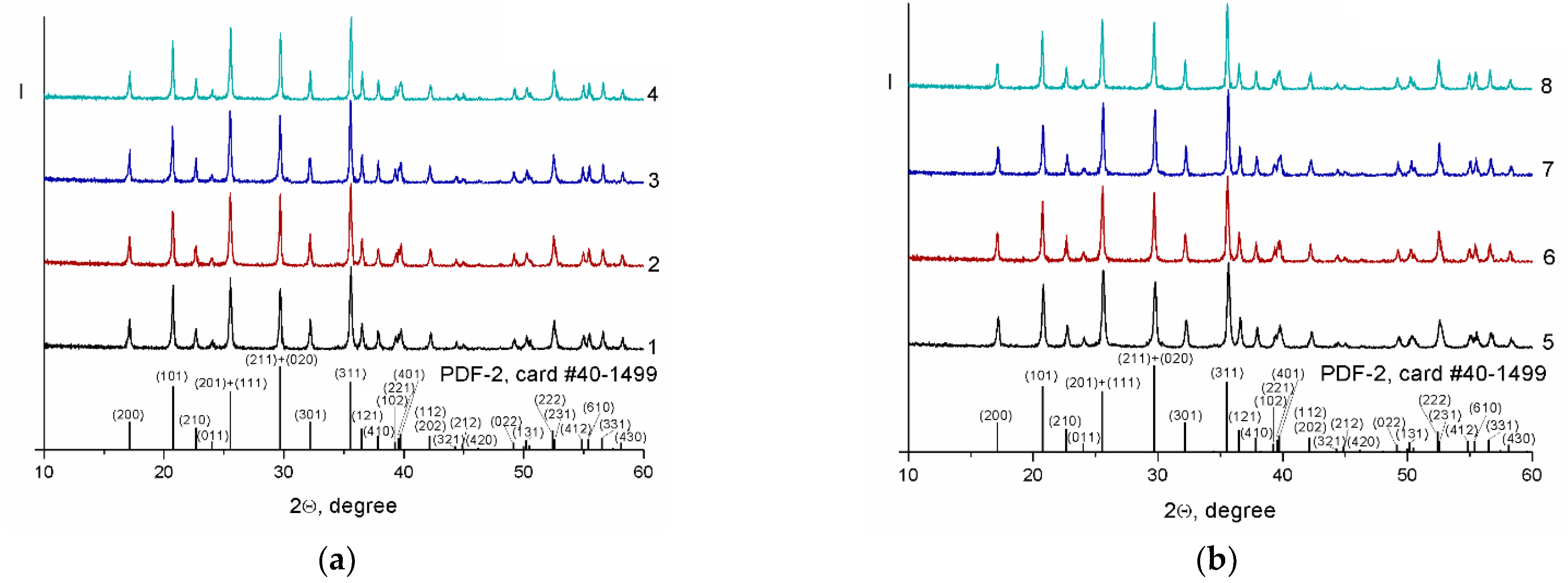
According to the XRD analysis (Figure 1), all reflexes of the prepared composites could be indexed in the orthorhombic modification of olivine-structured LiFePO4 (PDF-2 database, nos. 40–1499). Wide weak diffraction peaks in the 2Θ region of 24–26°, which are characteristic of graphene and carbon nanofibers and correspond to the plane with Miller indices (002), were not detected due to the strong peak (111) of lithium iron phosphate at 25.5°.
The crystallite size (CSR) of lithium iron phosphate in the composites prepared using sucrose as a pyrolytic carbon source was, in general, slightly larger than that in the composites fabricated using PVDF (Table 1). This may have been due to the presence of fluorine in the material, which was most likely sorbed at the interface between LFP and carbon, or a slightly larger amount of carbon in the latter (12–13 and 15–16 wt.% for LFP/CSucr/CNM and LFP/CPVDF/CNM composites, respectively). As a result of the mechanical treatment of the LFP precursor in a planetary mill before the final annealing, the size of the primary LiFePO4 particles decreased somewhat. For all composites containing carbon nanofibers, the size of LiFePO4 crystallites turned out to be somewhat smaller than in the composites prepared with carbon nanoplatelets. Apparently, CNFs were distributed over the surface of the LFP precursor particles, limiting their growth during annealing. Carbon nanoplatelets, which are agglomerates of considerable size (from 2 to 40 μm), cannot provide a uniform coating of lithium iron phosphate precursor particles even in the case of high-energy ball milling.
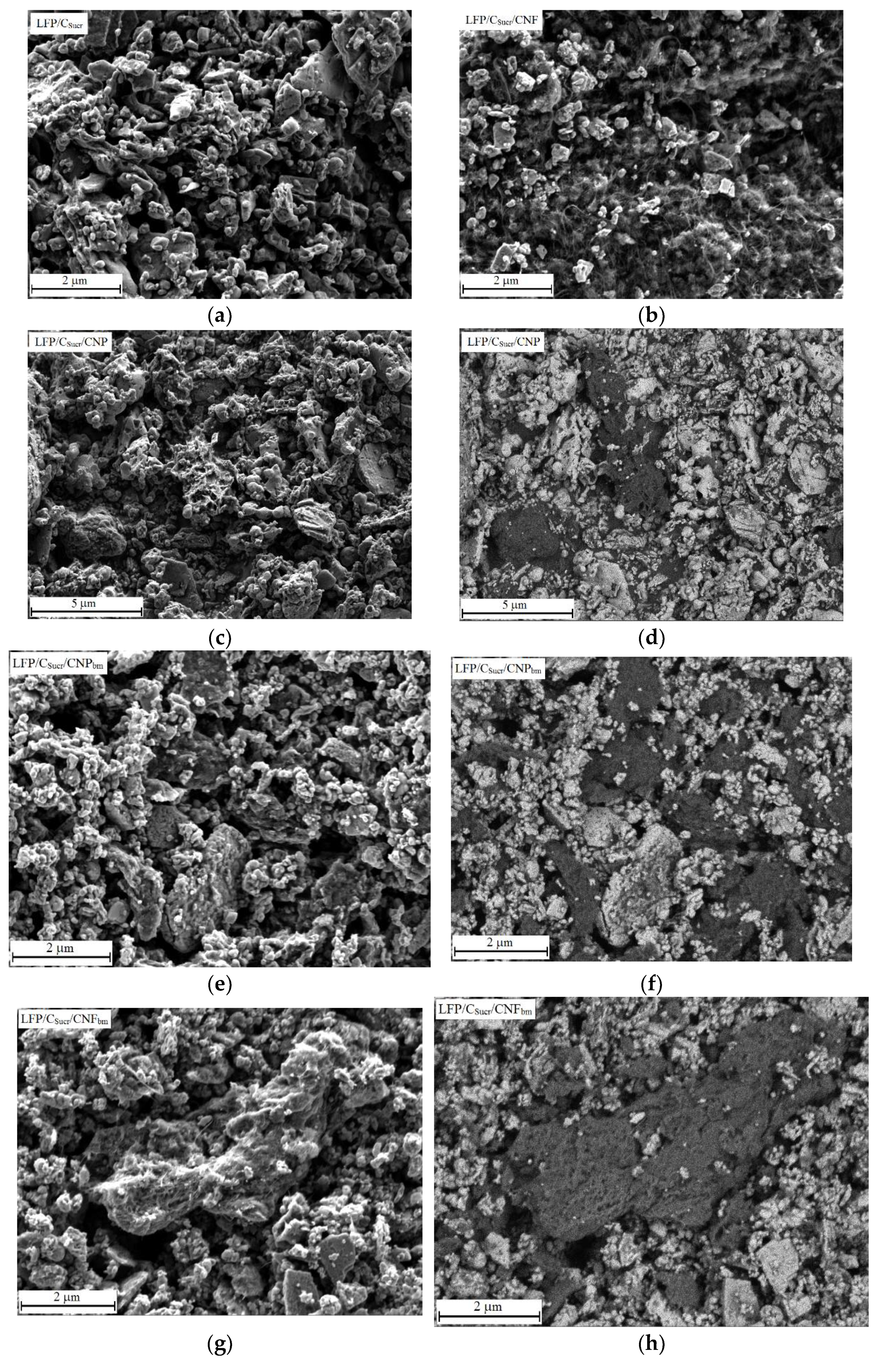
As can be seen in Figure 2, the introduction of carbon nanomaterials during LiFePO4 synthesis did not lead to a significant change in morphology. However, both the amount of crystallite agglomerates and their size decreased somewhat. Large agglomerates of carbon nanoplatelets (up to 5–7 μm in size) were observed among lithium iron phosphate particles in all of the LFP/C/CNP composites, which were better seen in the backscattered SEM images (Figure 2d,l). Joint ball milling of the LFP precursor with carbon nanoplatelets did not lead to a significant decrease in the size of the CNP agglomerates (Figure 2f). In the LFP/CSucr/CNF composites prepared by grinding the LFP precursor in a mortar, carbon nanofibers covered the LFP surface, forming an electron-conductive network (Figure 2b). At the same time, SEM images of LFP/CPVDF/CNF and the composites prepared by mechanical treatment of the LFP precursor with CNFs in a planetary mill showed only agglomerates of carbon nanofibers (Figure 2g–i). Apparently, the use of a hydrophilic medium (ethanol) during ball milling leads to the agglomeration of hydrophobic carbon nanomaterials, which is most pronounced in the case of CNFs (carbon nanoplatelets are initially agglomerates). In addition, the CNFs in the agglomerates appeared to be somewhat amorphous (Figure 2g), which may indicate their partial destruction.
According to the low-temperature nitrogen adsorption data (Table 1), the specific surface areas of the bare LFP/CSucr and LFP/CPVDF were 35 and 54 m2/g, respectively. Since those of the carbon nanofibers and carbon nanoplatelets were 598 and 1198 m2/g, respectively, the specific surface areas of the composites based on them changed accordingly. Thus, for the LFP/CSucr/CNF, LFP/CPVDF/CNF, LFP/CPVDF/CNP, and LFP/CSucr/CNP materials, the specific surface areas were ca. 65, 91, 71, and 92 m2/g, respectively. For samples obtained by ball milling of the LFP precursor with carbon nanomaterials, the specific surface areas were lower. For example, for LFP/CSucr/CNFbm and LFP/CSucr/CNPbm, the values were 48 and 64 m2/g, respectively. This may have been due to the above-mentioned agglomeration of carbon nanomaterials or their partial destruction upon ball milling with harder LFP particles.
The electronic conductivity of the prepared composites increased by several orders of magnitude when PVDF was used instead of sucrose as a pyrolytic carbon source (from 4.6 × 10⁻⁷ S/cm for LFP/CSucr to 8.6 × 10⁻⁵ S/cm for LFP/CPVDF). Carbon nanomaterial introduction leads to a more pronounced increase in electronic conductivity. The LFP/CSucr/CNF and LFP/CPVDF/CNF composites showed the maximum conductivities (Table 1). Contrary to expectations, the mechanical treatment of the LFP precursor with carbon nanofibers in a planetary mill resulted in a decrease in the conductivity of the prepared composites compared to those of the samples fabricated via less intensive treatment methods in an agate mortar. Apparently, the reason for this was the agglomeration of CNFs in hydrophilic ethanol during ball milling or their partial destruction. This is consistent with a decrease in the specific surface areas of the composites (Table 1). On the contrary, the composites made with carbon nanoplatelets fabricated via ball milling exhibited higher electronic conductivities compared to materials whose precursors were ground in a mortar (Table 1). Due to the higher intensity of the processing, ball milling leads to a partial destruction of carbon nanoplatelet agglomerates and a more uniform distribution over the composite bulk. The use of PVDF instead of sucrose as a carbon source led to high electronic conductivities for all the composites.
Figure S1 shows the charge–discharge profiles at different charge–discharge rates of all the prepared composites in a potential range of 2.5 to 4.1 V. All the composites showed typical potential plateaus at ~3.4 V associated with the Fe3+PO4 ↔ LiFe2+PO4 redox reaction. As current density increases, the diffusion of lithium ions and electrons in the layer of the forming phase is hindered so that they cannot go all the way from the surface to the center of the FePO4 particles and the capacities of materials decrease. As can be seen from Figure S1, the LFP/CSucr/CNF composite exhibited longer charge–discharge plateaus and narrower gaps between them compared with the other composites, suggesting a lower polarization resistance, which was due to the CNFs forming a conducting network structure.
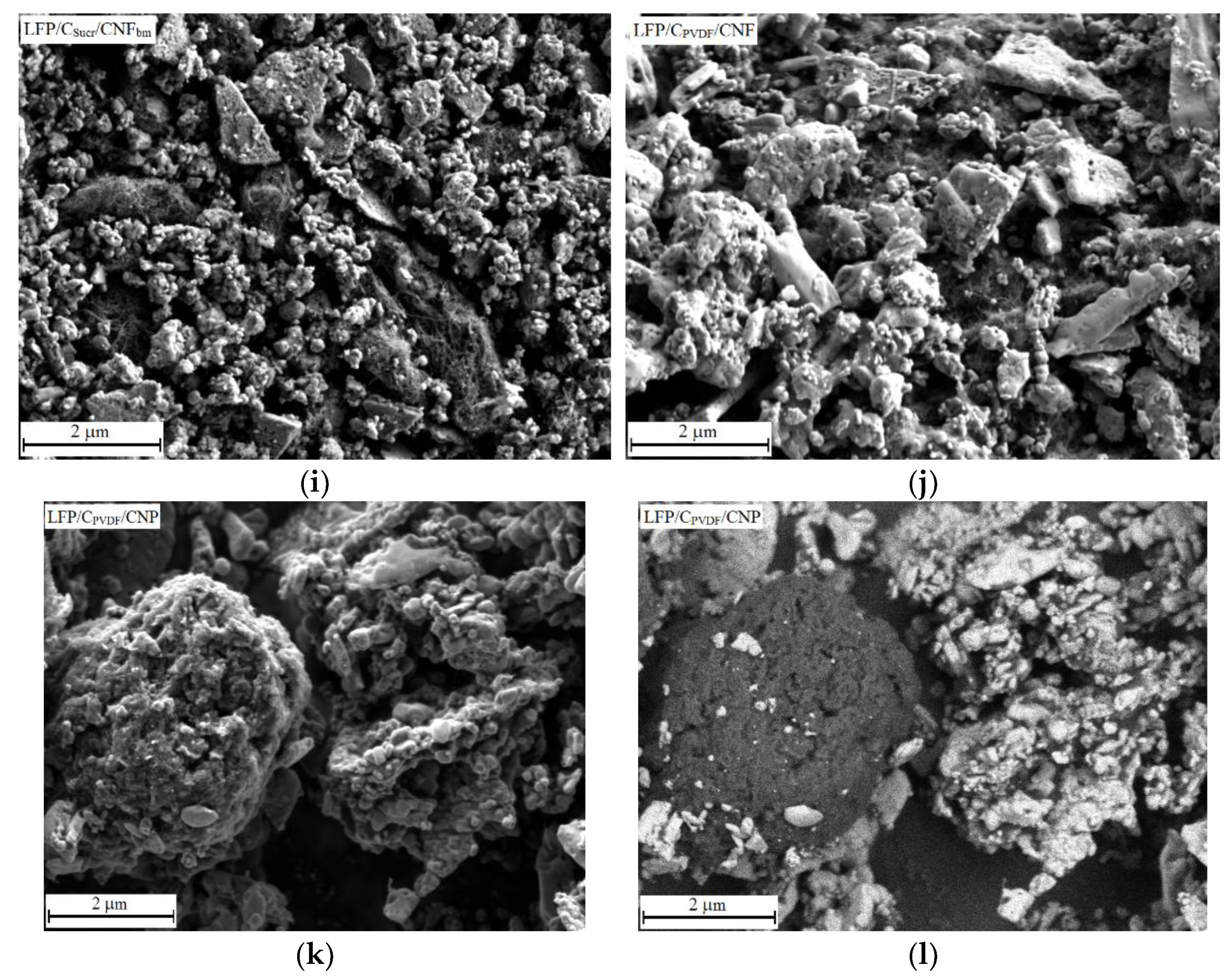
Data on the cycling performances of the prepared composites are shown in Figure 3. When sucrose was used as a pyrolitic carbon source, the composites prepared by grinding of the LFP precursor with carbon nanomaterials in an agate mortar demonstrated better results compared to those prepared via ball milling across the entire range of charge–discharge rates (Figure 3a). The LFP/CSucr/CNF composite exhibited the highest reversible discharge capacity across the entire range of current densities. The observed results can be explained by smaller LiFePO4 crystallites in the LFP/CSucr/CNF (Table 1) and their better bonding via long carbon nanofibers, which ultimately led to the formation of more reliable conductive contacts between the particles of the cathode material, resulting in high electronic conductivity (Table 1). For example, at a current density of 3200 mA/g, the discharge capacity of LFP/CSucr/CNF was 85 mAh/g. Despite the close value of the discharge capacity of the LFP/CSucr/CNP sample at a high charge–discharge rate (81 mAh/g at a current density of 3200 mA/g), the degradation of this material was high (after returning to low currents, the capacity loss was 14.6%). Among the composites fabricated via ball milling, the LFP/CSucr/CNPbm material demonstrated the best performance at high charge–discharge rates (Figure 3b). Its discharge capacity was 130, 100, 79, and 58 mAh/g at a current density of 200, 800, 1600, and 3200 mA/g, respectively. It can be noted that in the case of composites prepared by ball milling of LFP/CSucr with carbon nanomaterials (ex situ synthesis), the highest capacity at a current density of 3200 mA/g did not exceed 55 mAh/g [36]. In the case of using PVDF as a pyrolitic carbon source, we expected synergy between the F-doped carbon coating and carbon nanomaterials. However, despite the fact that the discharge capacity of LFP/CPVDF was higher than that of LFP/CSucr, there was no significant increase in discharge capacity with the introduction of carbon nanomaterials compared to LFP/CPVDF (Figure 3b). In addition, the capacities of composites made with carbon nanomaterials based on LFP/CPVDF were lower than those of similar composites based on LFP/CSucr. The most likely reason for this is that, when using PVDF, the carbon nanomaterials are significantly agglomerated rather than being evenly distributed over the LFP surface, as is the case with sucrose and carbon nanofibers. Nevertheless, in almost all of the studied composites, the decrease in the capacity of LiFePO4 with increasing current density was mainly due to kinetic factors, since, after cycling at high currents, capacity at low currents was restored almost to the initial value (the degradation of most materials did not exceed 3–5%), and in some cases even exceeded it.
At low C rates, the reversible discharge capacities of the LFP composites made with carbon nanomaterials fabricated in this work were comparable to those reported in the literature and exceeded them in some cases (Table 2). However, at high charge–discharge rates, the obtained capacities turned out to be somewhat lower (Table 2). It is obvious that the carbon nanomaterial acts as an effective electron carrier, and the capacities of composites are determined by the electrode material (LiFePO4) and largely depend on the morphologies of its particles, which, in turn, are determined by the method of synthesis. In a number of works cited, hydrothermal and spray-drying synthesis methods were used, allowing the preparation of nanosized electrode materials with rather narrow particle size distributions, leading to higher capacities for these materials compared to those synthesized by the sol–gel method or solid-state reactions. Thus, a simple synthesis method, e.g., a sol–gel method, should be used for accurate assessment of the effect of a carbon additive.
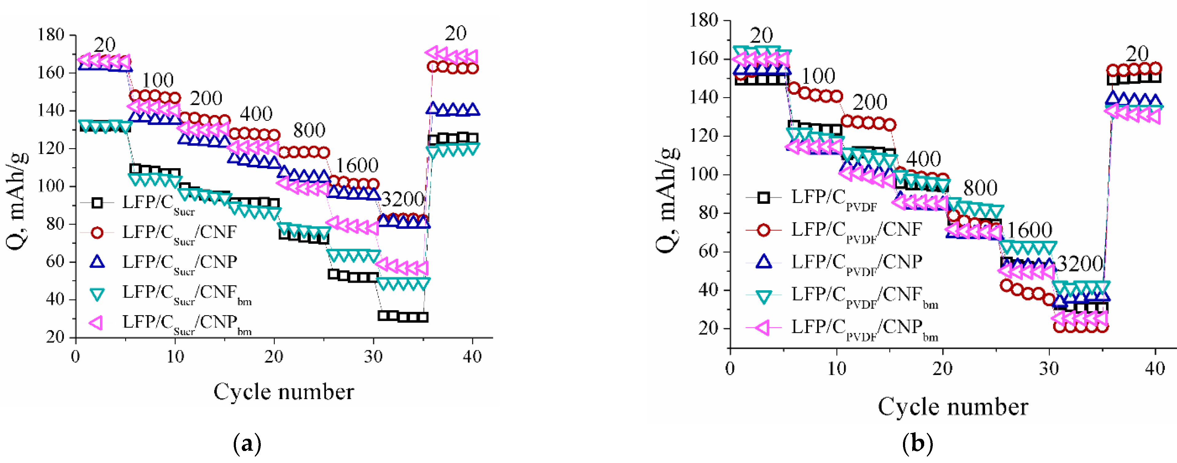
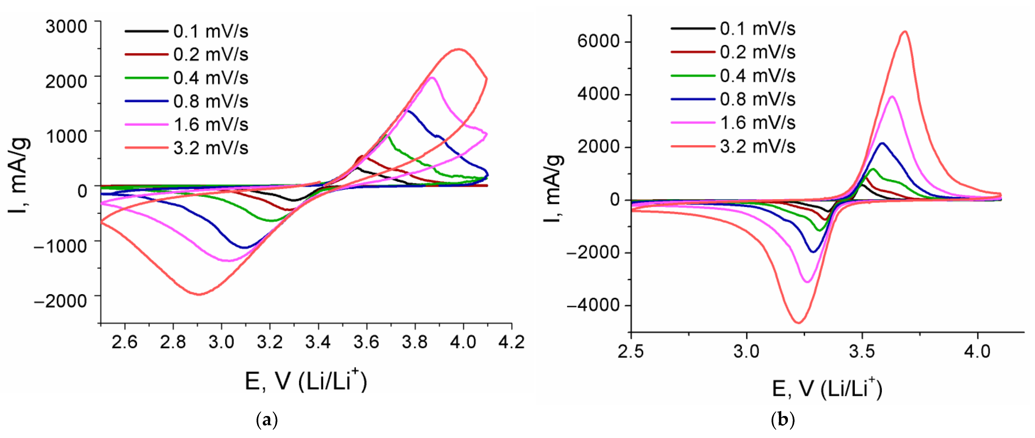
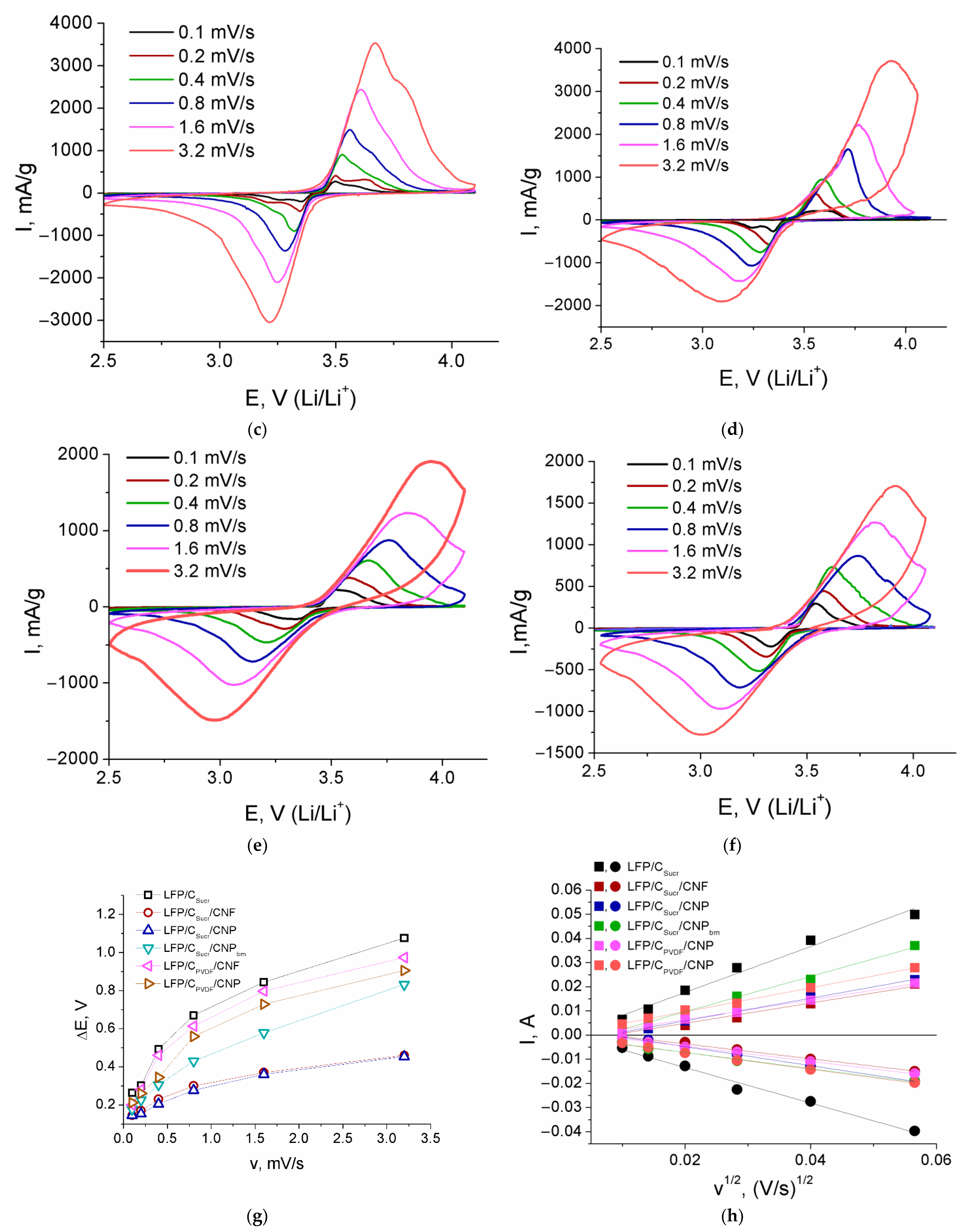
Cyclic voltammograms of some LFP-based composites with carbon nanomaterials are shown in Figure 4. The maxima observed in the cathode and anode regions correspond to the redox reaction between Fe2+ and Fe3+. The peaks in the CV curve of the LFP/CSucr/CNF sample appear to be more intense and narrow than those of other samples. For the LFP/CSucr/CNF and LFP/CSucr/CNP samples, the potential differences between the cathodic and anodic current peaks (∆E), reflecting the degree of electrode polarization, were almost the same, e.g., at 3.2 mV/s, 0.46 and 0.45 V, respectively (Figure 4g). The LFP/CSucr composite exhibited the highest ∆E in the whole range of the potential sweep rates, e.g., 1.07 V at 3.2 mV/s. In the case of a high barrier to electron transfer, more positive or negative potentials (for oxidation or reduction, respectively) are required for electron transfer. This results in a larger potential difference between the cathodic and anodic current peaks. Thus, the higher the ΔE, the lower the reversibility. Among the studied composites, LFP/CSucr and LFP/CPVDF/CNF showed the lowest reversibility. The data obtained indicate that in the case of the LFP/CSucr/CNF sample, the formation of a three-dimensional network of carbon nanofibers “binding” LFP particles resulted in an improvement in redox kinetics, with charge transfer growth and reduced electrode polarization. For all samples, a slight splitting of the peaks on the CV curves could be noted. A similar effect was observed when studying the influence of calcination temperature and carbon nanotube proportion on the electrochemical properties of LFP, described elsewhere [37]. The authors attributed the observed dependence to a slow diffusion of lithium ions into the material bulk through the layer of the formed product (LiFePO4 and FePO4 during reduction and oxidation, respectively).
Figure 4e shows relationships between the cathodic and anodic peak currents and the square root of the scan rate. They are linear; thus, the Randles−Sevcik equation can be used for the estimation of the diffusion coefficient of Li+ ions (DLi) in the composite:
where Ip is the value of the peak current, n is the electron transfer number (for LiFePO4, n = 1), C0 is the initial concentration of lithium ions in LiFePO4, S is the surface area of the electrode, and v is the scan rate [19]. According to the equation (1), the Li+ diffusion coefficient is proportional to the slope of the linear dependence of Ip vs. v1/2 in the second degree. The lithium diffusion coefficients for the reduction and oxidation processes of LFP in LFP/CSucr/CNF were found to be 2.1 × 10⁻¹¹ and 4.1 × 10⁻¹¹ cm2/s, while those of LFP/CSucr/CNP were 1.4 × 10⁻¹¹ and 2.1 × 10⁻¹¹ cm2/s, and those of LFP/CPVDF/CNF were 8.1 × 10⁻¹² and 1.5 × 10⁻¹¹ cm2/s, respectively (Table 3). The diffusion coefficient of lithium ions for the LFP/CSucr/CNF composite was somewhat larger, which agrees with the results of galvanostatic tests.
Ip = 2.69 × 10⁵n3/2C0SDLi1/2v1/2
4. Conclusions
In this work, the effects of various carbon nanomaterials (carbon nanofibers and carbon nanoplatelets), as well as various carbon sources, on the electrochemical properties of composites based on olivine-structured lithium iron phosphate were studied. The introduction of all of the carbon nanomaterials led to increases in the electronic conductivities and reversible electrochemical capacities of the composites. Due to the formation of efficient transport systems for lithium ions and electrons, carbon nanofibers are more efficient for the improvement of the electrochemical properties of electrode materials. Although the composites fabricated using PVDF as the pyrolitic carbon source showed increased electrical conductivities, their rate capabilities were worse than those of the composites prepared using sucrose. Joint ball milling of the LFP precursor with carbon nanomaterials led to a decrease in the size of LFP particles, the amorphization and agglomeration of CNFs, and had almost no effect on the size of the CNP agglomerates. Therefore, it had rather a negative effect on the properties of the materials.
Supplementary Materials
The following supporting information can be downloaded at: https://www.mdpi.com/article/10.3390/batteries8090111/s1.
Author Contributions
Conceptualization, I.S. and A.Y.; methodology, I.S. and T.K; investigation, P.M., I.S. and T.K; data curation, A.Y.; writing—original draft preparation, I.S. and T.K.; writing—review and editing, T.K., I.S. and A.Y.; supervision, I.S.; project administration, I.S.; funding acquisition, I.S. All authors have read and agreed to the published version of the manuscript.
Funding
This research was funded by the Russian Foundation for Basic Research, grant number 20-08-00769.
Institutional Review Board Statement
Not applicable.
Informed Consent Statement
Not applicable.
Data Availability Statement
The data presented in this study are available upon request from the corresponding author.
Acknowledgments
This research was performed using the equipment of the JRC PMR IGIC RAS.
Conflicts of Interest
The authors declare no conflict of interest.
References
- Nitta, N.; Wu, F.; Lee, J.T.; Yushin, G. Li-ion battery materials: Present and future. Mater. Today 2015, 18, 252–264. [Google Scholar] [CrossRef]
- Grey, C.P.; Hall, D.S. Prospects for lithium-ion batteries and beyond—A 2030 vision. Nat. Commun. 2020, 11, 6279. [Google Scholar] [CrossRef] [PubMed]
- Yang, J.; Liu, X.; Tian, J.; Ma, X.; Wang, B.; Li, W.; Wang, Q. Adhesive nanocomposites of hypergravity induced Co3O4 nanoparticles and natural gels as Li-ion battery anode materials with high capacitance and low resistance. RSC Adv. 2017, 7, 21061–21067. [Google Scholar] [CrossRef]
- Wang, Y.; Liu, C.; Pan, R.; Chen, Z. Modeling and State-of-Charge Prediction of Lithium-Ion Battery and Ultracapacitor Hybrids with a Co-Estimator. Energy 2017, 121, 739–750. [Google Scholar] [CrossRef]
- Duh, Y.S.; Lin, K.H.; Kao, C.S. Experimental investigation and visualization on thermal runaway of hard prismatic lithium-ion batteries used in smart phones. J. Therm. Anal. Calorim. 2018, 132, 1677–1692. [Google Scholar] [CrossRef]
- Galushkin, N.E.; Yazvinskaya, N.N.; Galushkin, D.N. Mechanism of thermal runaway in lithium-ion cells. J. Electrochem. Soc. 2018, 165, 1303–1308. [Google Scholar] [CrossRef]
- Kang, Y.; Deng, C.; Chen, Y.; Liu, X.; Liang, Z.; Li, T.; Hu, Q.; Zhao, Y. Binder-Free Electrodes and Their Application for Li-Ion Batteries. Nanoscale Res. Lett. 2020, 15, 112. [Google Scholar] [CrossRef]
- Chen, S.; Zhang, X.; Xia, M.; Wei, K.; Zhang, L.; Zhang, X.; Cui, Y.; Shu, J. Issues and challenges of layered lithium nickel cobalt manganese oxides for lithium-ion batteries. J. Electroanal. Chem. 2021, 895, 115412. [Google Scholar] [CrossRef]
- Dunn, B.; Kamath, H.; Tarascon, J.M. Electrical Energy Storage for the Grid: A Battery of Choices. Science 2011, 334, 928–935. [Google Scholar] [CrossRef]
- Chen, Y.; Kang, Y.; Zhao, Y.; Wang, L.; Liu, J.; Li, Y.; Liang, Z.; He, X.; Li, X.; Tavajohi, N.; et al. A review of lithium-ion battery safety concerns: The issues, strategies, and testing standards. J. Energy Chem. 2021, 59, 83–99. [Google Scholar] [CrossRef]
- Susantyoko, R.; Alkindi, T.S.; Kanagaraj, A.B.; An, B.; Alshibli, H.; Choi, D.; Aldahmani, S.; Fadaq, H.; Almheiri, S. Performance optimization of freestanding MWCNF-LiFePO4 sheets as cathodes for improved specific capacity of lithium-ion batteries. RSC Adv. 2018, 8, 16566–16573. [Google Scholar] [CrossRef] [PubMed]
- Wang, Y.; Zhu, B.; Wang, Y.; Wang, F. Solvothermal synthesis of LiFePO4 nanorods as high-performance cathode materials for lithium ion batteries. Ceram. Int. 2016, 42, 10297–10303. [Google Scholar] [CrossRef]
- Chen, Z.; Zhang, Q.; Liang, Q. Carbon-Coatings Improve Performance of Li-Ion Battery. Nanomaterials 2022, 12, 1936. [Google Scholar] [CrossRef] [PubMed]
- Voropaeva, D.Y.; Safronova, E.Y.; Novikova, S.A.; Yaroslavtsev, A.B. Recent progress in lithium-ion and lithium metal batteries. Mendeleev Commun. 2022, 32, 287–297. [Google Scholar] [CrossRef]
- Wang, H.; Wang, R.; Liu, L.; Jiang, S.; Ni, L.; Bie, X.; Yang, X.; Hu, J.; Wang, Z.; Chen, H.; et al. In-situ self-polymerization restriction to form core-shell LiFePO4/C nanocomposite with ultrafast rate capability for high-power Li-ion batteries. Nano Energy 2017, 39, 346–354. [Google Scholar] [CrossRef]
- Li, Q.Y.; Zheng, F.H.; Huang, Y.G.; Zhang, X.H.; Wu, Q.; Fu, D.J.; Zhang, J.J.; Yin, J.C.; Wang, H.Q. Surfactants assisted synthesis of nano-LiFePO4/C composite as cathode materials for lithium-ion batteries. J. Mater. Chem. A 2015, 3, 2025–2035. [Google Scholar] [CrossRef]
- Stenina, I.A.; Yaroslavtsev, A.B. Nanomaterials for lithium-ion batteries and hydrogen energy. Pure Appl. Chem. 2017, 89, 1185–1194. [Google Scholar] [CrossRef]
- Saroha, R.; Panwar, A.K.; Sharma, Y.; Tyagi, P.K.; Ghosh, S. Development of surface functionalized ZnO-doped LiFePO4/C composites as alternative cathode material for lithium ion batteries. Appl. Surf. Sci. 2017, 394, 25–36. [Google Scholar] [CrossRef]
- Li, X.; Yu, L.; Cui, Y.; Li, A.; Shao, H.; Shao, Z.; Zhang, W.; Shao, Z. Enhanced properties of LiFePO4/C cathode materials co-doped with V and F ions via high-temperature ball milling route. Int. J. Hydrogen Energy 2019, 44, 27204–27213. [Google Scholar] [CrossRef]
- Harrison, K.L.; Bridges, C.A.; Paranthaman, M.P.; Segre, C.U.; Katsoudas, J.; Maroni, V.A.; Idrobo, J.C.; Goodenough, J.B.; Manthiram, A. Temperature dependence of aliovalent-vanadium doping in LiFePO4 cathodes. Chem. Mater. 2013, 25, 768–781. [Google Scholar] [CrossRef]
- Yu, Z.; Jiang, L. Olivine LiFePO4 nanocrystals grown on nitrogen-doped grapheme sheets as high-rate cathode for lithium-ion batteries. Solid State Ion. 2018, 325, 12–16. [Google Scholar] [CrossRef]
- Zhan, T.T.; Jiang, W.F.; Li, C.; Luo, X.D.; Lin, G.; Li, Y.W.; Xiao, S.H. High performed composites of LiFePO4/3DG/C based on FePO4 by hydrothermal method. Electrochim. Acta 2017, 246, 322–328. [Google Scholar] [CrossRef]
- Yaroslavtsev, A.B.; Stenina, I.A. Carbon coating of electrode materials for lithium-ion batteries. Surf. Innov. 2021, 9, 92–110. [Google Scholar] [CrossRef]
- He, Z.; Jiang, Y.; Zhu, J.; Wang, H.; Li, Y.; Zhou, H.; Meng, W.; Dai, L.; Wang, L. N-doped carbon coated LiTi2(PO4)3 as superior anode using PANi as carbon and nitrogen bi-sources for aqueous lithium ion battery. Electrochim. Acta 2018, 279, 279–288. [Google Scholar] [CrossRef]
- Lei, C.; Han, F.; Li, D.; Li, W.-C.; Sun, Q.; Zhang, X.-Q.; Lu, A.-H. Dopamine as the coating agent and carbon precursor for the fabrication of N-doped carbon coated Fe3O4 composites as superior lithium ion anodes. Nanoscale 2013, 5, 1168–1175. [Google Scholar] [CrossRef] [PubMed]
- Tiwari, I.; Sharma, P.; Nebhani, L. Polybenzoxazine-an enticing precursor for engineering heteroatom-doped porous carbon materials with applications beyond energy, environment and catalysis. Mater. Today Chem. 2022, 23, 100734. [Google Scholar] [CrossRef]
- Zhang, W.; Hu, Z.; Fan, C.; Liu, Z.; Han, S.; Liu, J. Construction and Theoretical Calculation of an Ultra-High-Performance LiVPO4F/C Cathode by B-Doped Pyrolytic Carbon from Poly(vinylidene Fluoride). ACS Appl. Mater. Interfaces 2021, 13, 15190–15204. [Google Scholar] [CrossRef] [PubMed]
- Stenina, I.A.; Kulova, T.L.; Skundin, A.M.; Yaroslavtsev, A.B. Effects of carbon coating from sucrose and PVDF on electrochemical performance of Li4Ti5O12/C composites in different potential ranges. J. Solid State Electrochem. 2018, 22, 2631–2639. [Google Scholar] [CrossRef]
- Wang, X.; Feng, Z.; Hou, X.; Liu, L.; He, M.; He, X.; Huang, J.; Wen, Z. Fluorine doped carbon coating of LiFePO4 as a cathode material for lithium-ion batteries. Chem. Eng. J. 2020, 379, 122371. [Google Scholar] [CrossRef]
- Lei, X.; Zhang, H.; Chen, Y.; Wang, W.; Ye, Y.; Zheng, C.; Deng, P.; Shi, Z. A three-dimensional LiFePO4/carbon nanotubes/graphene composite as a cathode material for lithium-ion batteries with superior high-rate performance. J. Alloys Compd. 2015, 626, 280–286. [Google Scholar] [CrossRef]
- Luo, G.-Y.; Gu, Y.-J.; Liu, Y.; Chen, Z.-L.; Huo, Y.-l.; Wu, F.-Z.; Mai, Y.; Dai, X.-Y.; Deng, Y. Electrochemical performance of in situ LiFePO4 modified by N-doped graphene for Li-ion batteries. Ceram. Int. 2021, 47, 11332–11339. [Google Scholar] [CrossRef]
- Sun, X.; Zhang, L. Outstanding Li-storage performance of LiFePO4@MWCNFs cathode material with 3D network structure for lithium-ion batteries. J. Phys. Chem. Solid. 2018, 116, 216–221. [Google Scholar] [CrossRef]
- Kim, M.-S.; Lee, G.-W.; Lee, S.-W.; Jeong, J.H.; Mhamane, D.; Roh, K.C.; Kim, K.-B. Synthesis of LiFePO4/graphene microspheres while avoiding restacking of graphene sheet’s for high-rate lithium-ion batteries. J. Ind. Eng. Chem. 2017, 52, 251–259. [Google Scholar] [CrossRef]
- Li, Y.; Wang, L.; Zhang, H.; Liang, F.; Yao, Y.; Zhang, K. Freeze drying under vacuum assisted synthesis of LiFePO4@MWCNFs composite with phytic acid as phosphorus source for advanced Li-storage. Vacuum 2021, 193, 110541. [Google Scholar] [CrossRef]
- Deng, F.; Zeng, X.R.; Zou, J.Z.; Huang, J.F.; Sheng, H.C.; Xiong, X.B.; Qian, H.X.; Li, X.H. Synthesis of LiFePO4 in situ vapor-grown carbon fiber (VGCF) composite cathode material via microwave pyrolysis chemical vapor deposition. Chin. Sci. Bull. 2011, 56, 1832–1835. [Google Scholar] [CrossRef]
- Stenina, I.A.; Minakova, P.V.; Kulova, T.L.; Desyatov, A.V.; Yaroslavtsev, A.B. LiFePO4/carbon nanomaterial composites for cathodes of high-power lithium ion batteries. Inorg. Mater. 2021, 57, 620–628. [Google Scholar] [CrossRef]
- Li, W.; Garg, A.; Le, M.L.P.; Ruhatiya, C.; Gao, L.; Tran, V.M. Electrochemical performance investigation of LiFePO4/C0.15-x (x=0.05, 0.1, 0.15 CNTs) electrodes at various calcination temperatures: Experimental and Intelligent Modelling approach. Electrochim. Acta 2020, 330, 135314. [Google Scholar] [CrossRef]
- Wang, B.; Liu, T.; Liu, A.; Liu, G.; Wang, L.; Gao, T.; Wang, D.; Zhao, X.S. A Hierarchical Porous C@LiFePO4/Carbon Nanotubes Microsphere Composite for High-Rate Lithium-Ion Batteries: Combined Experimental and Theoretical Study. Adv. Energy Mater. 2016, 6, 1600426. [Google Scholar] [CrossRef]
- Sun, X.; Li, J.; Shi, C.; Wang, Z.; Liu, E.; He, C.; Du, X.; Zhao, N. Enhanced electrochemical performance of LiFePO4 cathode with in-situ chemical vapor deposition synthesized carbon nanotubes as conductor. J. Power Sources. 2012, 220, 264–268. [Google Scholar] [CrossRef]
- Xu, J.; Chen, G.; Li, X. Electrochemical performance of LiFePO4 cathode material coated with multi-wall carbon nanotubes. Mater. Chem. Phys. 2009, 118, 9–11. [Google Scholar] [CrossRef]
- Yang, J.; Wang, J.; Li, X.; Wang, D.; Liu, J.; Liang, G.; Gauthier, M.; Li, Y.; Geng, D.; Li, R.; et al. Hierarchically porous LiFePO4/nitrogen-doped carbon nanotubes composite as a cathode for lithium ion batteries. J. Mater. Chem. 2012, 22, 7537–7543. [Google Scholar] [CrossRef]
- Shih, J.-Y.; Lin, G.-Y.; Li, Y.-J.J.; Hung, T.-F.; Jose, R.; Karuppiah, C.; Yang, C.-C. Operando investigation on the fast two-phase transition kinetics of LiFePO4/C composite cathodes with carbon additives for lithium-ion batteries. Electrochim. Acta 2022, 419, 140356. [Google Scholar] [CrossRef]
- Rajoba, S.J.; Jadhav, L.D.; Kalubarme, R.S.; Patil, P.S.; Varma, S.; Wani, B.N. Electrochemical performance of LiFePO4/GO composite for Li-ion batteries. Ceram. Int. 2018, 44, 6886–6893. [Google Scholar] [CrossRef]
- Ren, X.; Li, Z.; Cao, J.; Tian, S.; Zhang, K.; Guo, J.; Wen, L.; Liang, G. Enhanced rate performance of the mortar-like LiFePO4/C composites combined with the evenly coated of carbon aerogel. J. Alloys Compd. 2021, 867, 158776. [Google Scholar] [CrossRef]
Figure 1.
X-ray diffraction patterns of composites based on lithium iron phosphate and carbon nanomaterials: LFP/CSucr/CNF (1), LFP/CSucr/CNP (2), LFP/CPVDF/CNF (3), LFP/CPVDF/CNP (4), LFP/CSucr/CNFbm (5), LFP/CSucr/CNPbm (6), LFP/CPVDF/CNFbm (7), and LFP/CPVDF/CNPbm (8). The LFP precursor and carbon nanomaterials were processed in an agate mortar (a) and in a planetary mill (b).

Figure 2.
SEM images of the LFP/CSucr (a), LFP/CSucr/CNF (b), LFP/CSucr/CNP (c,d), LFP/CSucr/CNPbm (e,f), LFP/CSucr/CNFbm (g–i), LFP/CPVDF/CNF (j), and LFP/CPVDF/CNP (k,l) samples. (a–c,e,g, i–k)—secondary electron images; (d,f,h,l)—backscattered electron images (darker areas on the latter correspond to elements with lower atomic numbers (in this case, carbon)).


Figure 3.
Change in discharge capacity during cycling of the composites prepared using sucrose (a) and PVDF (b) as carbon sources. The numbers over the curves indicate current densities (mA/g).
Figure 3.
Change in discharge capacity during cycling of the composites prepared using sucrose (a) and PVDF (b) as carbon sources. The numbers over the curves indicate current densities (mA/g).

Figure 4.
Cyclic voltammograms at different potential sweep rates for the LFP/CSucr (a), LFP/CSucr/CNF (b), LFP/CSucr/CNP (c), LFP/CSucr/CNPbm (d), LFP/CPVDF/CNF (e), and LFP/CPVDF/CNP (f) samples; the potential difference between the cathodic and anodic current peaks (g); the dependence of the peak current on the square root of the scan rate (h). Circles correspond to LFP reduction; squares correspond to LFP oxidation.


Table 1.
Crystallite size (CSR), carbon content, electronic conductivity, and specific surface area values for the LFP/C/CNM composites.
Table 1.
Crystallite size (CSR), carbon content, electronic conductivity, and specific surface area values for the LFP/C/CNM composites.
| Composite | Crystallite Size ± 1, nm | Carbon Content, ±0.1 wt.% | Electronic Conductivity, S/cm | Specific Surface Area, m2/g |
|---|---|---|---|---|
| LFP/CSucr | 75 | 4.7 | 4.6 × 10⁻⁷ | 35 |
| LFP/CPVDF | 69 | 7.5 | 8.6 × 10⁻⁵ | 54 |
| LFP/CSucr/CNF | 60 | 12.1 | 1.3 × 10⁻² | 65 |
| LFP/CSucr/CNP | 73 | 12.5 | 3.6 × 10⁻⁴ | 91 |
| LFP/CSucr/CNFbm | 58 | 12.5 | 3.2 × 10⁻³ | 48 |
| LFP/CSucr/CNPbm | 68 | 12.8 | 9.7 × 10⁻³ | 64 |
| LFP/CPVDF/CNF | 67 | 15.2 | 1.2 × 10⁻² | 71 |
| LFP/CPVDF/CNP | 68 | 15.7 | 9.2 × 10⁻⁴ | 92 |
| LFP/CPVDF/CNFbm | 61 | 15.1 | 4.6 × 10⁻³ | 68 |
| LFP/CPVDF/CNPbm | 64 | 15.5 | 1.2 × 10⁻³ | 90 |
Table 2.
The effect of carbon additives on the electrochemical performances of some LFP/C composites.
Table 2.
The effect of carbon additives on the electrochemical performances of some LFP/C composites.
| Carbon Additive/ its Content | Preparation Method/ Calcination Conditions | Capacity, mAh/g (C Rate) | Ref. |
|---|---|---|---|
| CNTs/10 wt.% | Hydrothermal/800 °C, 6 h, N2 | 160 (0.1 C) | [37] |
| CNTs/6 wt.% | Hydrothermal/600 °C, 6 h, Ar/H2 | 155 (0.2 C), 126 (5 C) | [38] |
| CNTs/13 wt.% | Chemical vapor deposition/675 °C, 30 min, C2H2/Ar | 161 (0.1 C)/119 (5 C) | [39] |
| MWCNTs/5 wt.% | Hydrothermal/700 °C, 6 h, Ar | 139 (0.3 C)/102 (3 C) | [40] |
| N-doped CNTs/11 wt.% | Sol–gel/700 °C, 10 h, Ar | 142 (0.1 C)/82 (5 C) | [41] |
| MWCNTs/4.5 wt.% | Spray drying/700 °C, 10 h, Ar/H2 | 157 (0.2 C), 131 (5 C) | [32] |
| Graphene/4 wt.% | Solid-state reaction/650 °C, 10 h, Ar | 165 (0.2 C), 124 (5 C) | [30] |
| Porous graphene oxide/1 wt.% | Spray drying/700 °C, 10 h, Ar/H2 | 151 (0.1 C), 126 (5 C) | [42] |
| Graphene oxide/4 wt.% | solution combustion/700 °C, 5 h, N2 | 163 (0.1 C), 60 (2 C) | [43] |
| Vapor-grown carbon fiber/14.5 wt.% | Microwave pyrolysis chemical vapor deposition/800 °C, 10 min, propylene | 148 (0.1 C), 144 (0.5 C) | [35] |
| Carbon aerogel/2.6 wt.% | Spray drying/720 °C, 5 h, N2 | 152 (0.2 C), 134 (5 C) | [44] |
| F-doped coating/10 wt.% | Solid-state reaction/600 °C, 8 h, Ar | 145 (0.1 C), 113 (5 C) | [29] |
| Carbon nanofibers/10 wt.% | Sol–gel/600 °C, 10 h, Ar | 169 (0.1 C), 121 (5 C) | This work |
Table 3.
The calculated Li+ diffusion coefficients for some composites of LFP and carbon nanomaterials.
Table 3.
The calculated Li+ diffusion coefficients for some composites of LFP and carbon nanomaterials.
| Sample | Redox Process | Slope of the Dependence of Ip vs. v1/2 | DLi, cm2/s |
|---|---|---|---|
| LFP/CSucr | Reduction | −0.734 | 2.1 × 10⁻¹² |
| Oxidation | 0.950 | 3.6 × 10⁻¹² | |
| LFP/CSucr/CNF | Reduction | −0.308 | 2.1 × 10⁻¹¹ |
| Oxidation | 0.419 | 4.1 × 10⁻¹¹ | |
| LFP/CSucr/CNP | Reduction | −0.393 | 1.4 × 10⁻¹¹ |
| Oxidation | 0.469 | 2.1 × 10⁻¹¹ | |
| LFP/CSucr/CNPbm | Reduction | −0.336 | 2.8 × 10⁻¹² |
| Oxidation | 0.679 | 1.1 × 10⁻¹¹ | |
| LFP/CPVDF/CNF | Reduction | −0.315 | 8.1 × 10⁻¹² |
| Oxidation | 0.407 | 1.5 × 10⁻¹¹ | |
| LFP/CPVDF/CNP | Reduction | −0.349 | 1.8 × 10⁻¹² |
| Oxidation | 0.493 | 3.4 × 10⁻¹² |
Publisher’s Note: MDPI stays neutral with regard to jurisdictional claims in published maps and institutional affiliations. |
© 2022 by the authors. Licensee MDPI, Basel, Switzerland. This article is an open access article distributed under the terms and conditions of the Creative Commons Attribution (CC BY) license (https://creativecommons.org/licenses/by/4.0/).
Share and Cite
MDPI and ACS Style
Stenina, I.; Minakova, P.; Kulova, T.; Yaroslavtsev, A. Electrochemical Properties of LiFePO4 Cathodes: The Effect of Carbon Additives. Batteries 2022, 8, 111. https://doi.org/10.3390/batteries8090111
AMA Style
Stenina I, Minakova P, Kulova T, Yaroslavtsev A. Electrochemical Properties of LiFePO4 Cathodes: The Effect of Carbon Additives. Batteries. 2022; 8(9):111. https://doi.org/10.3390/batteries8090111
Chicago/Turabian StyleStenina, Irina, Polina Minakova, Tatiana Kulova, and Andrey Yaroslavtsev. 2022. "Electrochemical Properties of LiFePO4 Cathodes: The Effect of Carbon Additives" Batteries 8, no. 9: 111. https://doi.org/10.3390/batteries8090111
Note that from the first issue of 2016, this journal uses article numbers instead of page numbers. See further details here.